JP4795239B2 - Disposable cups attached to spray guns for making, installing and storing paint - Google Patents
Disposable cups attached to spray guns for making, installing and storing paintDownload PDFInfo
- Publication number
- JP4795239B2 JP4795239B2JP2006524469AJP2006524469AJP4795239B2JP 4795239 B2JP4795239 B2JP 4795239B2JP 2006524469 AJP2006524469 AJP 2006524469AJP 2006524469 AJP2006524469 AJP 2006524469AJP 4795239 B2JP4795239 B2JP 4795239B2
- Authority
- JP
- Japan
- Prior art keywords
- movable element
- disposable cup
- paint
- valve
- plug
- Prior art date
- Legal status (The legal status is an assumption and is not a legal conclusion. Google has not performed a legal analysis and makes no representation as to the accuracy of the status listed.)
- Expired - Fee Related
Links
- 239000003973paintSubstances0.000titleclaimsabstractdescription44
- 239000007921spraySubstances0.000titleclaimsabstractdescription14
- 230000005484gravityEffects0.000claimsdescription4
- 238000010422paintingMethods0.000claimsdescription3
- 239000000463materialSubstances0.000claimsdescription2
- 230000000295complement effectEffects0.000claims3
- 238000001914filtrationMethods0.000claims1
- 238000002360preparation methodMethods0.000abstractdescription3
- 238000004321preservationMethods0.000abstract1
- 230000006870functionEffects0.000description5
- 239000000243solutionSubstances0.000description5
- 230000008901benefitEffects0.000description4
- 238000007789sealingMethods0.000description4
- 230000000694effectsEffects0.000description3
- 238000004519manufacturing processMethods0.000description3
- 238000000034methodMethods0.000description3
- 230000002093peripheral effectEffects0.000description3
- 238000009423ventilationMethods0.000description3
- 230000008859changeEffects0.000description2
- 239000010409thin filmSubstances0.000description2
- 101100327917Caenorhabditis elegans chup-1 geneProteins0.000description1
- 210000000078clawAnatomy0.000description1
- 238000004140cleaningMethods0.000description1
- 239000011248coating agentSubstances0.000description1
- 238000000576coating methodMethods0.000description1
- 230000003247decreasing effectEffects0.000description1
- 230000000994depressogenic effectEffects0.000description1
- 239000010408filmSubstances0.000description1
- 230000008571general functionEffects0.000description1
- 238000001746injection mouldingMethods0.000description1
- 230000007246mechanismEffects0.000description1
- 239000012528membraneSubstances0.000description1
- 230000009467reductionEffects0.000description1
- 230000003014reinforcing effectEffects0.000description1
- 239000002904solventSubstances0.000description1
- 238000003860storageMethods0.000description1
- 238000013022ventingMethods0.000description1
Images


Classifications
- B—PERFORMING OPERATIONS; TRANSPORTING
- B05—SPRAYING OR ATOMISING IN GENERAL; APPLYING FLUENT MATERIALS TO SURFACES, IN GENERAL
- B05B—SPRAYING APPARATUS; ATOMISING APPARATUS; NOZZLES
- B05B7/00—Spraying apparatus for discharge of liquids or other fluent materials from two or more sources, e.g. of liquid and air, of powder and gas
- B05B7/24—Spraying apparatus for discharge of liquids or other fluent materials from two or more sources, e.g. of liquid and air, of powder and gas with means, e.g. a container, for supplying liquid or other fluent material to a discharge device
- B05B7/2402—Apparatus to be carried on or by a person, e.g. by hand; Apparatus comprising containers fixed to the discharge device
- B05B7/2405—Apparatus to be carried on or by a person, e.g. by hand; Apparatus comprising containers fixed to the discharge device using an atomising fluid as carrying fluid for feeding, e.g. by suction or pressure, a carried liquid from the container to the nozzle
- B05B7/2408—Apparatus to be carried on or by a person, e.g. by hand; Apparatus comprising containers fixed to the discharge device using an atomising fluid as carrying fluid for feeding, e.g. by suction or pressure, a carried liquid from the container to the nozzle characterised by the container or its attachment means to the spray apparatus
- B—PERFORMING OPERATIONS; TRANSPORTING
- B05—SPRAYING OR ATOMISING IN GENERAL; APPLYING FLUENT MATERIALS TO SURFACES, IN GENERAL
- B05B—SPRAYING APPARATUS; ATOMISING APPARATUS; NOZZLES
- B05B7/00—Spraying apparatus for discharge of liquids or other fluent materials from two or more sources, e.g. of liquid and air, of powder and gas
- B05B7/24—Spraying apparatus for discharge of liquids or other fluent materials from two or more sources, e.g. of liquid and air, of powder and gas with means, e.g. a container, for supplying liquid or other fluent material to a discharge device
- B05B7/2402—Apparatus to be carried on or by a person, e.g. by hand; Apparatus comprising containers fixed to the discharge device
- B05B7/2478—Gun with a container which, in normal use, is located above the gun
Landscapes
- Nozzles (AREA)
- Closures For Containers (AREA)
- Table Devices Or Equipment (AREA)
- Coating Apparatus (AREA)
- Containers And Packaging Bodies Having A Special Means To Remove Contents (AREA)
- Application Of Or Painting With Fluid Materials (AREA)
- Tubes (AREA)
Abstract
Description
Translated fromJapanese本発明は塗料を、作製し、施工し、未使用または残った塗料を保存するための吹付けガンを取り付けられた使い捨てカップに関する。The present invention relates to a disposable cup fitted with a spray gun for making, applying and preserving unused or remaining paint.
吹付けガンの塗装工は、塗料を作製する際、および塗料を1つの容器から他の容器へと移す際に、流出および塗料損失のリスクを生ぜしめる困難な作業へ直面しなければならないことは公知である。Spray gun painters must face the difficult task of creating spills and risk of spillage and paint loss when transferring paint from one container to another. It is known.
労働コストが増大するために、全ての雇用者はこの介入に対する迅速性を高めることができる解決策を探そうとしていることは公知である。As labor costs increase, all employers are known to seek solutions that can increase the speed of this intervention.
この風潮の中において、塗料作製中および塗布作業中に塗料を入れる使い捨てカップまたは可撓性の使い捨てバッグのために種々の解決策が開発されてきた。In this trend, various solutions have been developed for disposable cups or flexible disposable bags that contain paint during paint preparation and application operations.
これらの解決策により、機器の洗浄にかかる時間を短くするとともに、多くの場合環境に優しくない溶剤を基にした洗浄製品の使用が低減される。These solutions reduce the time it takes to clean the equipment and often reduce the use of cleaning products based on solvents that are not environmentally friendly.
残った塗料の問題への解決策は依然として残ったままである。これら残った塗料は長期間保存しておくものではなく、たとえば同様の目的で将来的な作業で用いられるものである。The solution to the remaining paint problem remains. These remaining paints are not stored for a long time, but are used in future work for the same purpose, for example.
さらに解決策が待たれる点は、塗装工の急な動きや、体のねじれ、深く体を傾けたことなどから起こる通気孔からの漏れによる塗料の損失などである。Further solutions are awaited by the painter's sudden movement, twisting of the body, loss of paint due to leaks from the vents caused by deep tilting.
本発明の一般的な目的は、これらの欠点に対処し、かつ特性を基にしたさらなる利点を提供することである。The general object of the present invention is to address these drawbacks and provide further advantages based on properties.
この目的を達成するために、本発明は、塗料の作製および、その塗料を吹付けガンへ適用するための使い捨てカップに関する。本願明細書のカップはガン、とくに重力ガンに取り付けられるものであり、かつ胴体部を有する。この胴体部は、たとえば、空気放出口と、排気口案内部が、ガンに固定または取り付けられるアダプタ上に固定された蓋部と、を有する底部を有する略円錐台形状の容器であり、カップはその壁部のうちの1枚に、稼動部分を有する閉鎖可能な通気孔装置を含んでいることを特徴とし、この装置はこれにより、開かれた場合には空気をカップ内に送り、空になった容量を満たし、閉じられた場合には少なくとも液体密閉態様において空気の流出を密封することが可能となり、塗料を作成したり、塗料の流出管を第2の可動部、好ましくは第1の可動部と同様なものにより閉じたりするための容器を作り上げて、残った塗料を保存するために、塗料が空気に接触することを防ぐ容器を提供する。To achieve this object, the present invention relates to a disposable cup for making a paint and applying the paint to a spray gun. The cup of the present specification is attached to a gun, particularly a gravity gun, and has a body part. The body portion is, for example, a substantially frustoconical container having a bottom portion having an air discharge port and a lid portion on which an exhaust port guide portion is fixed or attached to the gun. One of the walls is characterized in that it includes a closable venting device having an active part, whereby the device sends air into the cup when opened and emptied. When the closed volume is filled and closed, it is possible to seal the outflow of air at least in a liquid-sealed manner, to create a paint or to connect the paint outflow pipe to the second movable part, preferably the first A container is provided that prevents the paint from coming into contact with air in order to create a container that can be closed by something similar to a moving part and to store the remaining paint.
噴霧塗料を作製および施工するための使い捨てカップは、その胴体部1がたとえば、側面2と、底面3と、蓋部4とを含む略円筒状または円錐台の容器の形状をしている。The disposable cup for producing and applying the spray paint has a
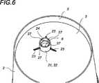
底部3は、底部3の延長部として下方周縁円状端部5があるため、下方端部から一定の距離だけ離間されて配置されている。側面2は、カップが水平面に平坦な支持部上に立てられた場合に安定性を与えられるように突出している。底部3は、通気孔を形成する開口部6により交差されており、これにより、大量の使用済み塗料を補充するようになされた空気を入れるとともに、塗料の流れを可能にする。この空気の流れをおこすための空気通路通気開口部6は図面に示されるように中央でなされても、その他でなされてもいずれでもよい。本発明にしたがった通気孔開口部は閉鎖可能な通気孔装置7に設けられる。Since the
側面2は平滑であるとともに、連続的な目盛でカップの高さに沿って延在する、目盛付けされたスケール部8を有して、全体として刻印されたり、印刷されたり、合致されたりする9などを形成する。側面2は図1に示される10などのいくつかの端部補強リブを設けられてもよい。The
胴体部1の上部面は漏斗形蓋部4により閉じられており、中心部内には、わずかに先を細くされ、かつ円錐形状である排気口管11を有する。蓋部4はその基部から、カップ1の胴体部側面の上方部12上にねじ止めされ、カップ上には13などのいくつかの連続的なリブ部が形成され、このリブ部は、たとえば不連続な、カップ胴体部上にねじ止めすることにより蓋部4の対応するねじ山形成部を受けるねじ山を形成する。蓋部には図8に示される内方のショルダー部14を有し、円盤形フィルター部15の周縁部を支持する。フィルター部は外周部環状接合部16(図3を参照のこと)により囲繞される。The upper surface of the
カップは、アダプタ部18により、塗料吹付けガン上に、好ましくは重力ガン17上に取り付けられるがこれに限定されるものではない。アダプタ部18はたとえば、ねじ留めされる中空の一片であってもよく、または突出部19の端部のうちの一方により、たとえばガンのねじ切られた突出部上に取り付けられたり、固定されたり、嵌合されて円錐形の勾配がつけられた取付具により、蓋部4の中央の円錐形の排気口管11を受けてもよい。当然、他の多くの接続手段あるいは、他の異なる現存するまたは今後のアダプタ部を適宜用いてもよい。The cup is mounted on the paint spray gun, preferably on the
嵌合されて円錐形の勾配がつけられた取付具による接続は分離が極めて難しいとともに、その使用法および作業中の塗装工の動きの点において、十分嵌合することが適切であるということが実証されている。Connections with mated and conically-graded fittings are extremely difficult to separate, and it is appropriate to fit well in terms of their usage and the movement of the painter during the work. Proven.
閉鎖可能な通気孔装置7を以下に説明する。The
閉鎖可能な通気孔装置7は、塗料作業中に空気を中に取り入れることで、一般的なバルブの機能を実現する。すなわち、カップが空になり、カップが塗料を作製するための容器として使用されている際に空気吸い込み口の通気孔開口部6が閉じられる場合である。The closeable
バルブ型の閉鎖可能な通気孔装置7は、可動要素20およびバルブ胴体部21を利用するが、それらに沿って可動要素20は、通気孔開口部6の閉位置と開位置との間を移動する。The valve-type
可動要素20はバルブ胴体部21内部で、その特定のそれぞれの位置で、すなわち閉位置および開位置で固定され、かつ手動運転中にはこれらの2つの位置の間で自由であることが好ましいが、これに限定されるものではない。It is preferred that the movable element 20 is fixed inside the valve body 21 in its particular respective position, i.e. in the closed position and in the open position, and is free between these two positions during manual operation. However, the present invention is not limited to this.
このために、底部3を介して空気経路用の通気孔開口部6は、バルブ胴体部として機能する、放射状のリブ部23により補強された中空の円筒基部22により囲繞される。このバルブの高さは環状端部5の上方稜線部により画定された面より低くなされるため、このため水平面が平坦な表面部上に載置されたカップは、塗料作製用の対応する直立した第2の位置において安定した位置を有する。For this purpose, the air
この中空の円筒基部22は管であり、これに沿って可動部20が移動する。The hollow
管を形成する基部22においては、環状リブ部24が内部側面から突出して成形される。環状リブ部24は、スナップイン位置設定リブと呼ばれ、可動要素20がバルブ管22内部を手動で移動するように、スナップイン位置設定を随時提供する。その形状から、この部分はバルブプラグ25と呼ばれてきた。バルブプラグ25は、バルブの開口および閉鎖を確実に2つの正確な位置になす。第1の位置は閉位置にあり、プラグの端部は底部3にわたって経路通気開口部6を満たし、底部3の内部面から突出することなく嵌合し、スナップ嵌め効果によりこの位置において固定される。第2の位置は、通気孔開位置と呼ばれ、この位置においてバルブプラグ25の端部は、カップの底部3にわたり経路の通気開口部6から離間して移動されるとともに、第2のスナップイン突出部により同位置に保持される。これらの位置は、図4および図5に示されるバルブプラグの位置と同様である。In the
上述の位置設定は当然、ネジ付チェーン止、切欠き、直角掛け、その他の方法でなされてもよい。Of course, the above-mentioned position setting may be performed by a threaded chain stop, a notch, a right angle hook, or other methods.
このために図7は、バルブプラグ25の実施形態の一例の構造を透視図で示す。To this end, FIG. 7 shows a perspective view of an exemplary structure of the
かかる実施形態にしたがうと、バルブプラグ25はたとえば、略円筒形で中空の胴体部であり、その一端部には上方端部円盤形を有し、その円周上方端部26は胴体部自体よりも径が大きく、このために上方位置設定ショルダー部を形成する。また他方の端部では、一端部により成端された下方端部正面が形成され、これにより、その端部がカップの底部の内部面から突出することなく、かつ取り付け具が、密封するために通気開口部6の部分と堅く締め付けるように接触することなく、底部3にわたって存在する通気開口部6を閉じさせる。According to such an embodiment, the
開位置に空気を取り込むために、管22の上方部と、プラグ25との間には遊びや間隙が設けられている。管22の上方部の内径を大きくすること、またはプラグ25の上方部の径を相関的に小さくすること、または双方を同時に行なうことにより、かかる遊びを得ることができる。プラグ25を中央位置に保持するためには、3または4の中央長手方向の突出部、たとえば適当な厚みを有する27などの半円筒形状の突出部が、管22の側面内部のより高い場所に設けられる。In order to take air into the open position, play and a gap are provided between the upper portion of the
逆の場合も同様に、これらの中央突出部はまたプラグ25の側面上に設けられてもよい。Similarly, in the reverse case, these central protrusions may also be provided on the sides of the
プラグは、たとえばピン型の勾配した突出部28の閉じた形状を有して、下方部分で終端するが、その形状および寸法は、通気孔可動部またはプラグが、低い閉位置にあるとき、押された位置で通気開口部6が完全な液密性を有するために適したものである。The plug has, for example, a closed shape with pin-shaped
プラグがその閉位置においてかかる開口部を閉鎖する場合には、開口部の形状に基づいてプラグの形状は当然変化してもよい。If the plug closes such an opening in its closed position, the shape of the plug may naturally change based on the shape of the opening.
プラグ25の2つの端部間には胴体部が延在している。この胴体部は略円筒形で、一側面は2つの環状溝部29と30とを有しこれらは、バルブ管22の環状突出リブ部24に対してスナップイン効果を有して運転されるようになされ、これにより後者を、開位置または閉位置に隣接する位置のうちのひとつに対応する、バルブプラグ25の一方または他方の溝部に位置設定する。A body portion extends between the two end portions of the
かかる形状は、すなわちプラグ25の側面用の突出部およびバルブ案内部22の側面用の溝部を使った一般的な機能を改変することなく、変更がなされたり、特に反転がなされたりしてもよい。Such a shape may be changed, or in particular reversed, without altering the general function using the side protrusions of the
プラグはプラスチック製である。プラグは中身が詰まっていても、中空でもよく、これにより一定の可撓性が得られる。The plug is made of plastic. The plug may be filled or hollow, which provides a certain flexibility.
さらに、閉鎖用ピン28は底部面3の薄膜、膜、局部弱所、弱化された点または区域を穿孔したり、引裂したり、押下したり、破壊してもよい。これらにより、製造段階および最初の使用時点で開口部6を閉じる。このためには、ピン28または端部の形状はこの機能にあった、たとえばさらに円錐形や鋭い先端部、またはこれらと同等なもの、その他の適切な形を有する。Furthermore, the
バルブプラグ25の下方端部より下側の側面には、2つの長手方向の通気孔切欠31および32が形成され、これらは対称的に対向し、その長さに沿って下方端部から延在する。これらの切欠の長さは、閉じた停止部に対応する切欠が第1の溝部29を貫通して、第2の溝部30に届くことなく後者を越えて延在する。バルブプラグ25が第1の押下位置にあるとき、環状突出部24の下に空気通路を形成するために、通気孔切欠31および32の深さにより、その基部は第1の溝部29の基部の下になる。すなわち、閉位置または第1の突出部にあるときに、環状リブ部24は第1の溝部29に係合する。Two
閉口部および開口部の停止位置はそれぞれ本発明にしたがったカップの、塗料を作成するための容器または吹付けガン塗料用のカップという2つの主な使用法に対応することは明らかである。It is clear that the closing position of the closure and the opening respectively correspond to two main uses of the cup according to the invention: a container for making paint or a cup for spray gun paint.
つめ車または圧締めまたは留め金などの全ての機構により、プラグを開閉2つの位置に保持することは可能である。さらに、その機能または位置の形態がわずかに逆置されてもそれらが本発明を変更させることはない。It is possible to hold the plug in the two open and closed positions by all mechanisms such as a toothed wheel or a clamp or a clasp. Further, even if the function or position is slightly reversed, they do not change the present invention.
また、蓋部4の排気口管端部11の内部形状は、補助的な閉鎖要素として第2のバルブプラグ33を受けるようになされてもよい。このようにして、本発明にしたがって、すなわち進行している作業用に特に作成された任意の量の残った塗料を保護し保存するなどの、カップのさらなる使用法が得られる。このために、排気口管11の特定の内部形状は必要ではない。これらの2つの部分の間で十分に嵌合された密封部により、必要な保存期間中、適宜暫定的に嵌合が確実になされる。The internal shape of the
第1のプラグ25と同様なプラグを第2のプラグ33に採用することが好ましいがこれは、プラスチックで作成され、射出成形により製造されるものと同じため費用が安く済むからである。It is preferable to use a plug similar to the
塗料の作製は、通気孔バルブが液密に閉鎖された位置にあるカップまたは、開口部が薄膜または皮膜または厚みが低減された壁部により閉じられたカップによりなされる。このため、水平面に平坦な面上に載置された場合の容器は、環状端部5が突出しているため安定した位置にあり、塗装工はカップ胴体部側面上の目盛り付きのスケール部8で作製を容易に行なうことができる。The paint is made by a cup in which the vent valve is in a liquid-tight closed position or a cup whose opening is closed by a thin film or film or a wall having a reduced thickness. For this reason, the container when placed on a flat surface in a horizontal plane is in a stable position because the
塗装を進めるためには、塗装工は単に、フィルター部を有する蓋部によりカップを閉じるだけの簡単かつ迅速な動きにより最終的に、吹付けガンをアダプタ部で、蓋部排気口にセットできる。これが可能になったのは勾配した円錐形の取付具によるものであり、吹付けガンを上側に回転させてカップと共に定位置に配置して、バルブプラグ25を開いた位置に移動させて、すなわち通気孔突出部が、スナップイン効果で第1溝部、すなわちスナップイン溝部に受けられる。したがって塗装工は塗料漏れや、カップが任意に斜めになった際に、上方から塗料が思わず流れ出てくるといった心配をすることなく、容易に作業ができる。In order to proceed with painting, the painter can finally set the spray gun at the lid outlet at the adapter part by simply and quickly moving the cup with the lid part having the filter part. This was made possible by a sloped cone-shaped fixture, with the spray gun rotated upwards and placed in place with the cup and the
本発明にしたがった、複数の利点を備えた、カップの使い捨ての特性のみならず、簡単に使用できること、ならびに二重の使用法およびのちに使用できる塗料の残りを保存するための塗料ポットとしての役割のために、他にも作成時に得られる利点がある。In accordance with the present invention, as a paint pot for storing not only the disposable properties of the cup, but also the ease of use as well as the double use and the rest of the paint that can be used later, with several advantages according to the invention Because of the role, there are other benefits that can be gained during creation.
バルブ22の中央突出部は、カップとして可動要素20を閉じるバルブにより覆われてもよい。したがって、中央密封部を示すキャップ部として合致するメス部は、密封形状により成端される略円錐形状にしたがって、下方に延在するが、これはたとえばかかる機能に応じたピンであってもよい。同様に密封ピンは、キャップ部が基部の下方面から突出することなく、低位置にあるとき、通気孔開口部6内にピン自体を堅く埋設する。
特定の位置は、前述された、または他の同様な形状のように溝部と環状突出部との間の協働により示されてもよい。空気経路は、円筒突出部内の長手方向の通路あるいは他の同等な手段または実施形態により実現される。The central protrusion of the
The particular location may be indicated by cooperation between the groove and the annular protrusion as described above or other similar shapes. The air path is realized by a longitudinal passage in the cylindrical projection or other equivalent means or embodiment.
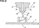
図9ないし図13は、閉鎖可能な通気孔装置の他の実施形態にしたがったものである。9 to 13 are in accordance with another embodiment of a closable vent device.
最初に図9はまず、たとえばその下方端部が通気孔開口部6の閉鎖用ピンにより成端されて、ねじ止めされたプラグ型34の他の実施形態を示す。プラグ34の胴体部は、中空の円筒基部22内部に収納された円筒の下方部分36を有する略T型形状である。この胴体部は、最終的にはさらに大きな部分が載せられる大きい径を有する円筒頭部37につながる。プラグ34の胴体部は中央内部チャネル部38を有し、空気をカップ内に通す。このチャネル部は下方端部に向かって39と40との2つの枝部に分岐している。
塗装時には空気経路の開いた位置に対応した高い位置にあり、また一方ではプラグが低位置にあるため、カップ底部のオリフィスまたは開口部は閉鎖用ピン35により確実に閉鎖される。First, FIG. 9 shows another embodiment of a
When painting, the orifice or opening at the bottom of the cup is securely closed by the
定位置またはプラグ34の位置で保持することにより、案内部は閉じた位置に向かって下方へ向かうともに、この位置での締付、たとえばねじ止めによる閉塞がなされる。したがって、オスねじ山41は、円筒突出部22の内部側面に形成されたメスねじ山42とともに配置されたプラグの、円筒部36の側面の突出部に形成される。この部分に完全にねじ止めされると、プラグはスナップイン突出部または例えばはさまりなどの他の任意の手段により保持される閉じた位置に対応する。同様の方法は高い開位置の場合においても当てはまる。直角掛け型の迅速に開閉する装置または他の任意の方法がまた用いられてもよい。By holding at the fixed position or the position of the
本発明の1つの特長にしたがうと、プラグが埋設されたとき、上方端部はカップ底部の突出部の上方稜線端部5の外方により画定された表面から突出しない。According to one feature of the invention, when the plug is embedded, the upper end does not protrude from the surface defined by the outside of the
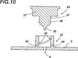
図10は、下方の閉鎖用ピン35と同様のプラグ43のさらなる実施形態を示す。この他の実施形態において、空気吸い込み口は、カップ底部の突出部22の円筒受け部の基部上に載置された44などの少なくとも1つまたは好ましくは2つの横断チャネルにより実現される。閉じた低位置への切替もまた、すなわち円筒突出部内方側部表面内のメスねじ山42と接触するプラグ胴体部の円筒部上のオスねじ山41により前述のようになされ、またはその逆も同様になされる。FIG. 10 shows a further embodiment of a
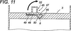
図11ないし図13に示されたさらに他の実施形態は、旋回胴体部型であり、これが傾けられてカップの底部壁部の厚みで隠される閉位置と、直立した開位置との間にある。Yet another embodiment shown in FIGS. 11-13 is a swivel fuselage mold, which is between a closed position that is tilted and hidden by the thickness of the bottom wall of the cup, and an upright open position. .
このさらに他の実施形態における旋回可動要素45の胴体部は、カップの底部壁部3に形成された空隙46内を旋回する略ホイッスル形状であり、たとえば対応する対向スロット内で締められて収容される47などの2つの横断爪部により形成される。この胴体部は空気通路チャネル48により長手方向に交差して、空隙基部46の開口部6に対面するまたは近傍の開位置、つまり図面に示されるようにカップの底部壁部3の通気孔開口部に抜ける。傾斜する可動要素45の胴体部は、直線の細長い部分49および球状部分50から構成される。球状部分50の下方部分は、停止および閉鎖用ピン51に合致する。このピンはカップの底部壁部3の開口部6を、閉じた下方傾斜位置で閉じて、旋回する可動要素45をこの位置で保持するためのものである。ピン51に対応する突出部は、後者の端部が、底部の内部表面から突出しないようにするが、突出したとしてもせいぜい、これと同一平面である。この閉鎖可能な通気孔装置の旋回する可動要素45は、旋回部が図12で示される開位置で停止し、カップ排気口の閉プラグが、図13に示される要求される残りの塗装を行なうので、ブロック52を把持手段として作用する横断突出部に備える。In this further embodiment, the body portion of the swivel
ピンは作業中の抵抗低減と十分な締め付けの両方を確実にする端部形状を有する。The pin has an end shape that ensures both resistance reduction and sufficient tightening during operation.
直線部分49を閉位置に対応する下方に傾斜した位置に収容するために、たとえば底部壁部3の厚み方向に対してくぼんだ対応する空隙53を設ける。このため底部壁部3は明らかにより厚くなければならない。In order to accommodate the
把持用ブロック52の高さは一定値より下であり、これにより環状端部5の上方稜線部により画定された表面部を超えることとなり、塗料作製位置でのカップの安定性を確実なものとする。The height of the
カップの胴体部用に、紫外線を濾光し、紫外線から塗料を守るために半透明または不透明な特定物質の使用を考慮してもよい。こういった考慮は感光性の製品の場合においては重要であることが立証されている。For cup bodies, the use of specific materials that are translucent or opaque to filter out the UV light and protect the paint from UV light may be considered. These considerations have proven important in the case of photosensitive products.
本発明の他の特長または利点を、一例として図面を添えて以下に説明する。Other features or advantages of the present invention are described below by way of example with reference to the drawings.
Claims (13)
Translated fromJapanese前記使い捨てカップは、円筒形状または円錐台形状の胴体部(1)と、前記胴体部(1)を閉じる蓋部(4)とを備え、
前記胴体部(1)は、通気孔開口部(6)が設けられた面を有する底部(3)を備え、前記通気孔開口部(6)は通気孔装置(7)により開閉可能な弁開閉式通気孔であって、前記通気孔装置(7)はバルブ胴体部(21)および前記バルブ胴体部(21)内で閉位置と開位置との間を移動可能な可動要素(20)有し、
前記可動要素(20)は、前記閉位置において前記通気孔開口部(6)を閉じ、前記開位置においては、前記通気孔開口部(6)から引き出されて前記通気孔開口部(6)を開く突出端部構造(28)を有しており、
前記蓋部(4)は、フィルタ(15)と、前記使い捨てカップを直接あるいはアダプタ部(18)を介して吹付けガン(17)に取り付けるための塗料の排出管(11)とを備え、
前記バルブ胴体部(21)は、中空の円筒基部(22)として形成された管状のバルブ胴体部であり、前記円筒基部(22)内をこれに沿って前記可動要素(20)が移動し、
手動により移動可能な前記可動要素(20)は、前記バルブ本体部(21)から取り外し可能であり、
前記可動要素(20)は前記バルブ胴体部(21)内で係合しており、前記バルブ胴体部(21)内を移動し、前記バルブ胴体部(21)内で、前記閉位置と前記開位置との2つの位置において固定され、
バルブ管(22)を形成する前記バルブ胴体部(21)と可動要素(20)との間に形成された空間、あるいは前記可動要素(20)内に形成された内部チャネル部は、前記可動要素(20)が開位置にあるときに、空気を自由に通過させるために用いられることで、前記可動要素(20)が前記バルブ胴体部(21)内で係合された状態で使い捨てカップ内に前記通気孔開口部(6)を通じて空気の流入が可能であることにより、
前記通気孔装置(7)により前記通気孔開口部(6)が開いたときに、塗装時に使用された塗料により作られた内部容量空間を満たすように空気を入れるとともに、前記通気孔装置(7)により前記通気孔開口部(6)が閉じたときに、前記使い捨てカップが塗料作成のための容器として用いられることを特徴とする使い捨てカップ。A disposable cup attached to a gravity gun (17) which is a spray gun for making, constructing and storing paint,
The disposable cup includes a cylindrical or truncated cone body (1) and a lid (4) for closing the body (1).
The body (1) includes a bottom (3) having a surface provided with a vent opening (6), and the vent opening (6) can be opened and closed by a vent device (7). The vent device (7) has a valve body part (21) and a movable element (20) movable between a closed position and an open position in the valve body part (21). ,
The movable element (20) closes the vent opening (6) in the closed position, and in the open position, the movable element (20) is pulled out of the vent opening (6) to open the vent opening (6). Having an open protruding end structure (28);
The lid (4) comprises a filter (15) and a paint discharge pipe (11) for attaching the disposable cup to the spray gun (17) directly or via the adapter part (18),
The valve body portion (21) is a tubular valve body portion formed as a hollow cylindrical base portion (22), and the movable element (20) moves along the inside of the cylindrical base portion (22),
Themovable element (20) that can be moved manually is removable from the valve body (21),
The movable element (20) is engaged in the valve body (21), moves in the valve body (21), and in the valve body (21), the closed position and the open position. Fixed at two positions with the position,
A space formed between the valve body part (21) and the movable element (20) forming the valve pipe (22), or an internal channel part formed in the movable element (20) includes the movable element. Used to allow air to freely pass when (20) is in the open position so that the movable element (20) is engaged in the disposable body with the valve body (21) engaged. By allowing air to flow in through the vent opening (6),
When the air vent opening (6) is opened by the air vent device (7), air is introduced so as to fill the internal volume space made by the paint used at the time of painting, and the air vent device (7). ), The disposable cup is used as a container for preparing a paint when the vent hole opening (6) is closed.
Applications Claiming Priority (3)
| Application Number | Priority Date | Filing Date | Title |
|---|---|---|---|
| FR03/10177 | 2003-08-26 | ||
| FR0310177AFR2859118B1 (en) | 2003-08-26 | 2003-08-26 | DISPOSABLE BUCKET TO BE MOUNTED ON A GUN FOR THE PREPARATION, APPLICATION AND PRESERVATION OF A PAINT |
| PCT/IB2004/003552WO2005018815A2 (en) | 2003-08-26 | 2004-08-26 | Disposable cup to be set up on a spray gun for preparing, applying and preserving a paint |
Publications (2)
| Publication Number | Publication Date |
|---|---|
| JP2007503303A JP2007503303A (en) | 2007-02-22 |
| JP4795239B2true JP4795239B2 (en) | 2011-10-19 |
Family
ID=34130601
Family Applications (1)
| Application Number | Title | Priority Date | Filing Date |
|---|---|---|---|
| JP2006524469AExpired - Fee RelatedJP4795239B2 (en) | 2003-08-26 | 2004-08-26 | Disposable cups attached to spray guns for making, installing and storing paint |
Country Status (18)
| Country | Link |
|---|---|
| US (2) | US7416140B2 (en) |
| EP (2) | EP1990099B1 (en) |
| JP (1) | JP4795239B2 (en) |
| CN (1) | CN100435972C (en) |
| AT (2) | ATE494073T1 (en) |
| AU (1) | AU2004266200B2 (en) |
| CA (1) | CA2508760C (en) |
| CY (1) | CY1109253T1 (en) |
| DE (2) | DE602004030959D1 (en) |
| DK (1) | DK1658143T3 (en) |
| ES (2) | ES2320347T3 (en) |
| FR (1) | FR2859118B1 (en) |
| PL (2) | PL1658143T3 (en) |
| PT (2) | PT1990099E (en) |
| RU (1) | RU2005120153A (en) |
| SI (1) | SI1658143T1 (en) |
| WO (1) | WO2005018815A2 (en) |
| ZA (1) | ZA200505296B (en) |
Families Citing this family (110)
| Publication number | Priority date | Publication date | Assignee | Title |
|---|---|---|---|---|
| ES2289363T3 (en)* | 2002-12-10 | 2008-02-01 | Martin Ruda | SINGLE WALL DEPOSIT FOR A SPRAY GUN AND PROCEDURE OF PRODUCTION OF A PLUG. |
| US7165732B2 (en) | 2004-01-16 | 2007-01-23 | Illinois Tool Works Inc. | Adapter assembly for a fluid supply assembly |
| US7086549B2 (en) | 2004-01-16 | 2006-08-08 | Illinois Tool Works Inc. | Fluid supply assembly |
| US7380680B2 (en) | 2004-01-16 | 2008-06-03 | Illinois Tool Works Inc. | Fluid supply assembly |
| DE102004003439B4 (en)* | 2004-01-22 | 2022-02-03 | Sata Gmbh & Co. Kg | Paint cup system for a paint spray gun |
| DE102004007733B4 (en)* | 2004-02-16 | 2014-02-13 | Sata Gmbh & Co. Kg | Gravity cup for a paint spray gun |
| US7568638B2 (en)* | 2004-04-29 | 2009-08-04 | Sata Gmbh & Co. Kg | Ventilated gravity cup for a paint spray gun |
| US7766250B2 (en) | 2004-06-01 | 2010-08-03 | Illinois Tool Works Inc. | Antistatic paint cup |
| US7354074B2 (en) | 2004-06-03 | 2008-04-08 | Illinois Tool Works Inc. | Adapter assembly for a fluid supply assembly |
| US7353964B2 (en) | 2004-06-10 | 2008-04-08 | Illinois Tool Works Inc. | Fluid supply assembly |
| CA2595531A1 (en) | 2005-01-31 | 2006-08-03 | Illinois Tool Works Inc. | Fluid supply assembly with measuring guide |
| US20070095943A1 (en)* | 2005-10-28 | 2007-05-03 | Turnbull William N | Liquid reservoir, and kit, spray assembly and method using same |
| EP1930084B1 (en) | 2006-12-05 | 2009-06-03 | SATA GmbH & Co. KG | Vent for the gravity cup of a paint spray gun |
| FR2916658A1 (en)* | 2007-05-30 | 2008-12-05 | Lir France Soc Par Actions Sim | VAPORIZER WITHOUT TUBE PLUNGER |
| EP2000218A1 (en)* | 2007-06-07 | 2008-12-10 | S.A. Omniform | Self regulating vent for a paint supply vessel. |
| PL2265387T3 (en) | 2008-03-12 | 2015-10-30 | Jeffrey D Fox | Disposable spray gun cartridge |
| US8666540B2 (en)* | 2008-03-28 | 2014-03-04 | Kirsten Elizabeth Milhorn | Color dispensing system and method |
| US20090272819A1 (en)* | 2008-04-30 | 2009-11-05 | Illinois Tool Works Inc. | Disposable liquid paint reservoir with internal support member for use with paint spray guns |
| DE202008014389U1 (en) | 2008-10-29 | 2010-04-08 | Sata Gmbh & Co. Kg | Gravity cup for a paint spray gun |
| TW201036707A (en)* | 2009-04-01 | 2010-10-16 | Victor Air Tools Co Ltd | Feeding structure of spray device |
| DE102009032399A1 (en) | 2009-07-08 | 2011-01-13 | Sata Gmbh & Co. Kg | Spray Gun |
| US9079201B2 (en) | 2010-01-22 | 2015-07-14 | Finishing Brands Holdings Inc. | Liquid supply system for a gravity feed spray device |
| DE202010007355U1 (en) | 2010-05-28 | 2011-10-20 | Sata Gmbh & Co. Kg | Nozzle head for a spraying device |
| US20120000992A1 (en)* | 2010-07-01 | 2012-01-05 | Hsien-Chao Shih | Paint cup structure of paintball gun |
| KR101053234B1 (en)* | 2010-07-26 | 2011-08-01 | 한정식 | Double pack |
| EP2646166B1 (en) | 2010-12-02 | 2018-11-07 | SATA GmbH & Co. KG | Spray gun and accessories |
| US8998111B2 (en)* | 2011-03-14 | 2015-04-07 | Pops Technologies Llc | Variable flow concentration product dispenser |
| EP2726212B2 (en) | 2011-06-30 | 2023-07-12 | SATA GmbH & Co. KG | Easy-to-clean spray gun, attachments for the same, and mounting and demounting methods |
| EP2650052B2 (en)* | 2012-04-13 | 2021-01-27 | J. Wagner AG | Powder beaker spray gun and spray coating device with same |
| JP6306584B2 (en)* | 2012-07-27 | 2018-04-04 | スリーエム イノベイティブ プロパティズ カンパニー | Vent assembly and reservoir including the same |
| CN103028528B (en)* | 2013-01-09 | 2015-08-19 | 浙江荣鹏气动工具有限公司 | Disposable spray gun paint cup lining bag |
| US9352343B2 (en) | 2013-01-22 | 2016-05-31 | Carlisle Fluid Technologies, Inc. | Liquid supply system for a gravity feed spray device |
| TWM469961U (en)* | 2013-05-09 | 2014-01-11 | Xing-Zi Wang | Paint gun container with leakproof vent cover |
| CA155474S (en) | 2013-09-27 | 2015-08-27 | Sata Gmbh & Co Kg | Spray gun |
| WO2015084617A1 (en) | 2013-12-05 | 2015-06-11 | 3M Innovative Properties Company | Container for a spraying device |
| DE202013105779U1 (en) | 2013-12-18 | 2015-03-19 | Sata Gmbh & Co. Kg | Air nozzle termination for a paint spray gun |
| USD758533S1 (en)* | 2014-06-02 | 2016-06-07 | Sata Gmbh & Co. Kg | Paint spray gun cup |
| CN105289870B (en) | 2014-07-31 | 2019-09-24 | 萨塔有限两合公司 | Manufacturing method of spray gun, spray gun, spray gun body and cover |
| CA159961S (en) | 2014-07-31 | 2015-07-17 | Sata Gmbh & Co Kg | Spray gun |
| USD758537S1 (en) | 2014-07-31 | 2016-06-07 | Sata Gmbh & Co. Kg | Paint spray gun rear portion |
| USD768820S1 (en) | 2014-09-03 | 2016-10-11 | Sata Gmbh & Co. Kg | Paint spray gun with pattern |
| US9796492B2 (en)* | 2015-03-12 | 2017-10-24 | Graco Minnesota Inc. | Manual check valve for priming a collapsible fluid liner for a sprayer |
| DE102015006484A1 (en) | 2015-05-22 | 2016-11-24 | Sata Gmbh & Co. Kg | Nozzle arrangement for a spray gun, in particular paint spray gun and spray gun, in particular paint spray gun |
| EP3319733B1 (en) | 2015-07-08 | 2020-11-11 | 3M Innovative Properties Company | Spray gun cups, receptacles, and methods of use |
| USD792556S1 (en) | 2015-07-08 | 2017-07-18 | 3M Innovative Properties Company | Spray gun cup receptacle |
| DE102015016474A1 (en) | 2015-12-21 | 2017-06-22 | Sata Gmbh & Co. Kg | Air cap and nozzle assembly for a spray gun and spray gun |
| WO2017123709A1 (en) | 2016-01-15 | 2017-07-20 | 3M Innovative Properties Company | Spray gun cups, receptacles, lids, and methods of use |
| PL3402604T3 (en) | 2016-01-15 | 2021-07-19 | 3M Innovative Properties Company | WIDE BORE CONNECTOR FOR LIQUIDS FOR HAND SPRAY GUNS |
| PL3842154T3 (en) | 2016-01-15 | 2025-06-09 | 3M Innovative Properties Company | Connector system for hand-held spray guns |
| CN112756126A (en) | 2016-01-15 | 2021-05-07 | 3M创新有限公司 | Spray gun cup, receiver and method of use |
| USD793531S1 (en) | 2016-03-24 | 2017-08-01 | 3M Innovative Properties Company | Spray gun cup receptacle |
| US10689165B2 (en) | 2016-01-15 | 2020-06-23 | 3M Innovative Properties Company | Reservoir systems for hand-held spray guns and methods of use |
| USD793530S1 (en) | 2016-03-24 | 2017-08-01 | 3M Innovative Properties Company | Lid for spray gun cup |
| EP3402601A1 (en) | 2016-01-15 | 2018-11-21 | 3M Innovative Properties Company | Modular spray gun lid assemblies and methods of design and use |
| USD811525S1 (en) | 2016-03-24 | 2018-02-27 | 3M Innovative Properties Company | Retention collar for spray gun cup |
| US20170239679A1 (en)* | 2016-02-23 | 2017-08-24 | Carlisle Fluid Technologies, Inc. | System and method having filter disposed in fluid supply cup |
| USD816800S1 (en)* | 2016-04-14 | 2018-05-01 | Bossauto Innova, S.A. | Spray gun cartridge |
| CN107364638B (en)* | 2016-05-12 | 2019-02-01 | 程鸿雁 | Air guide cover for washing-free paint liquid container |
| CN205995666U (en) | 2016-08-19 | 2017-03-08 | 萨塔有限两合公司 | Spray gun and its trigger |
| CN205966208U (en) | 2016-08-19 | 2017-02-22 | 萨塔有限两合公司 | Hood subassembly and spray gun |
| US10334866B2 (en)* | 2016-10-27 | 2019-07-02 | Rosina Haniszewski | Handheld assembly and method for uniform decoration of the sidewall for foodstuff |
| USD813985S1 (en) | 2016-12-12 | 2018-03-27 | 3M Innovative Properties Company | Spray gun liquid containment device |
| USD810867S1 (en)* | 2016-12-12 | 2018-02-20 | 3M Innovative Properties Company | Spray gun liquid containment device |
| USD810235S1 (en) | 2016-12-12 | 2018-02-13 | 3M Innovative Properties Company | Spray gun liquid containment device |
| USD812716S1 (en) | 2016-12-12 | 2018-03-13 | 3M Innovative Properties Company | Liquid containment device plug |
| USD810872S1 (en)* | 2016-12-12 | 2018-02-20 | 3M Innovative Properties Company | Shaker core |
| USD810864S1 (en) | 2016-12-12 | 2018-02-20 | 3M Innovative Properties Company | Spray gun liquid containment device |
| USD810870S1 (en)* | 2016-12-12 | 2018-02-20 | 3M Innovative Properties Company | Shaker core |
| USD810865S1 (en) | 2016-12-12 | 2018-02-20 | 3M Innovative Properties Company | Spray gun liquid containment device |
| USD833571S1 (en) | 2016-12-12 | 2018-11-13 | 3M Innovative Properties Company | Spray gun |
| USD804613S1 (en) | 2016-12-12 | 2017-12-05 | 3M Innovative Properties Company | Spray gun nozzle |
| USD810871S1 (en)* | 2016-12-12 | 2018-02-20 | 3M Innovative Properties Company | Shaker core |
| USD804614S1 (en) | 2016-12-12 | 2017-12-05 | 3M Innovative Properties Company | Adaptor for securing liquid containment device to spray gun |
| USD817443S1 (en) | 2016-12-12 | 2018-05-08 | 3M Innovative Properties Company | Spray gun liquid containment device |
| USD815248S1 (en) | 2016-12-12 | 2018-04-10 | 3M Innovative Properties Company | Spray gun liquid containment device |
| USD810863S1 (en)* | 2016-12-12 | 2018-02-20 | 3M Innovative Properties Company | Spray gun liquid containment device |
| USD810869S1 (en) | 2016-12-12 | 2018-02-20 | 3M Innovative Properties Company | Spray gun liquid containment device |
| USD810866S1 (en) | 2016-12-12 | 2018-02-20 | 3M Innovative Properties Company | Spray gun liquid containment device |
| USD810862S1 (en) | 2016-12-12 | 2018-02-20 | 3M Innovative Properties Company | Spray gun liquid containment device |
| USD810868S1 (en) | 2016-12-12 | 2018-02-20 | 3M Innovative Properties Company | Spray gun liquid containment device |
| JP6907559B2 (en) | 2017-01-26 | 2021-07-21 | セイコーエプソン株式会社 | Ink bottle |
| FR3062379B1 (en)* | 2017-01-27 | 2019-03-15 | Michel Camilleri | PAINT CONTAINER COMPRISING AN OPTIMIZED AIR INTAKE VALVE |
| CA3064970C (en)* | 2017-05-27 | 2022-09-06 | Shenzhen Wisdom Science And Technology Co., Ltd | Spray pot |
| JP2020528852A (en)* | 2017-07-14 | 2020-10-01 | スリーエム イノベイティブ プロパティズ カンパニー | Fluid delivery assembly for spray guns |
| CN108067936A (en)* | 2017-11-29 | 2018-05-25 | 艾来得科技(苏州)有限公司 | A kind of tapping self-service refueling device |
| CN111343889B (en)* | 2017-12-05 | 2022-12-27 | 雀巢产品有限公司 | Telescopic cup holder for beverage machine |
| DE102018118737A1 (en) | 2018-08-01 | 2020-02-06 | Sata Gmbh & Co. Kg | Nozzle for a spray gun, nozzle set for a spray gun, spray guns and method for producing a nozzle for a spray gun |
| CN112533705B (en) | 2018-08-01 | 2023-07-04 | 萨塔有限两合公司 | Nozzle bank for spray gun, spray gun system, method for manufacturing nozzle modules, method for selecting nozzle modules from nozzle banks for painting tasks, selection system and computer program product |
| DE102018118738A1 (en) | 2018-08-01 | 2020-02-06 | Sata Gmbh & Co. Kg | Base body for a spray gun, spray guns, spray gun set, method for producing a base body for a spray gun and method for converting a spray gun |
| CN113195107A (en) | 2018-12-12 | 2021-07-30 | 3M创新有限公司 | Liquid spray gun, connector ring, liquid spray device and adapter system |
| USD918340S1 (en)* | 2019-05-01 | 2021-05-04 | Tony ZHENG | Paint cup |
| EP3976270A1 (en) | 2019-05-31 | 2022-04-06 | Graco Minnesota Inc. | Handheld fluid sprayer |
| FR3097451B1 (en) | 2019-06-21 | 2021-10-01 | Michel Camilleri | DISPOSABLE MICROPOROUS VENT BUCKET |
| US20220401978A1 (en)* | 2019-11-11 | 2022-12-22 | 3M Innovative Properties Company | Vent assemblies |
| CN111389608B (en)* | 2019-12-23 | 2024-11-29 | 青岛汉柏塑料科技有限公司 | Spray gun liquid reservoir closure and spray gun liquid reservoir |
| USD971725S1 (en) | 2020-03-12 | 2022-12-06 | 3M Innovative Properties Company | Container lid |
| USD937968S1 (en) | 2020-03-12 | 2021-12-07 | 3M Innovative Properties Company | Container |
| USD971729S1 (en) | 2020-03-12 | 2022-12-06 | 3M Innovative Properties Company | Container lid |
| DE102020109914A1 (en) | 2020-04-08 | 2021-10-14 | Sata Gmbh & Co. Kg | Color cup with ventilation valve |
| CN111438020B (en)* | 2020-04-22 | 2024-09-13 | 青岛汉柏塑料科技有限公司 | Storage cup and spray gun liquid reservoir |
| WO2022010835A1 (en)* | 2020-07-06 | 2022-01-13 | SEM Products, Inc. | Adapter for connecting a fluid reservoir can to a fluid applicator |
| DE102020120229A1 (en)* | 2020-07-31 | 2022-02-03 | Sata Gmbh & Co. Kg | Gravity cup for a spray gun with an aeration device |
| DE102020120228A1 (en) | 2020-07-31 | 2022-02-03 | Sata Gmbh & Co. Kg | Gravity cup for a spray gun with an aeration device |
| CN111907874B (en)* | 2020-08-31 | 2022-08-02 | 微山县兄弟玻璃制品有限公司 | Leak protection type wine brewing tank |
| DE102020123769A1 (en) | 2020-09-11 | 2022-03-17 | Sata Gmbh & Co. Kg | Sealing element for sealing a transition between a base body of a spray gun and an add-on part of a spray gun, add-on part, in particular paint nozzle arrangement, for a spray gun and spray gun, in particular paint spray gun |
| CN113731669B (en)* | 2021-08-30 | 2022-07-15 | 深圳市慧智慧科技有限公司 | Fluid storage tank |
| CN113695100B (en)* | 2021-09-07 | 2024-10-29 | 青岛汉柏塑料科技有限公司 | Fluid supply cup for paint spray gun |
| CN113828433B (en)* | 2021-11-10 | 2024-10-18 | 青岛汉柏塑料科技有限公司 | Ventilated fluid supply cup |
| CN114749295A (en)* | 2022-01-07 | 2022-07-15 | 青岛汉柏塑料科技有限公司 | Novel fluid supply cup |
| CA216837S (en)* | 2022-03-29 | 2023-09-15 | Qingdao Hanbo Plastic Tech Co Ltd | Paint spray for use in building |
Citations (3)
| Publication number | Priority date | Publication date | Assignee | Title |
|---|---|---|---|---|
| JPH07289956A (en)* | 1994-04-19 | 1995-11-07 | Ransburg Corp | Coating material spray gun |
| JP2001508698A (en)* | 1997-01-24 | 2001-07-03 | ミネソタ・マイニング・アンド・マニュファクチャリング・カンパニー | Liquid spray device and disposable storage container and liner suitable for use with the device |
| WO2003045575A1 (en)* | 2001-11-14 | 2003-06-05 | Martin Ruda | Spray gun tank with a fixed liner |
Family Cites Families (26)
| Publication number | Priority date | Publication date | Assignee | Title |
|---|---|---|---|---|
| US3240398A (en)* | 1964-03-09 | 1966-03-15 | Sharpe Mfg Company | Vented spray gun cup |
| US4832232A (en)* | 1988-04-08 | 1989-05-23 | Broccoli Anthony B | Spray gun vent |
| US5042840A (en)* | 1989-04-19 | 1991-08-27 | Diversey Corporation | Refillable tank car for storing and transporting fluids |
| CN2203629Y (en)* | 1994-07-30 | 1995-07-19 | 周云辉 | Jet type spray gun |
| US5655714A (en)* | 1994-12-08 | 1997-08-12 | Wagner Spray Tech Corporation | Pivotable syphon tube |
| US5816501A (en)* | 1996-12-16 | 1998-10-06 | Ransburg Corporation | Disposable paint container liner and method |
| CN2291128Y (en)* | 1997-08-05 | 1998-09-16 | 王文斌 | Medical wound cleaning sterilizer |
| EA002043B1 (en)* | 1997-11-24 | 2001-12-24 | Энергеа Умвельттехнологи Гмбх | Method for producing fattymethyl ester and equipmentfor realizing the same |
| FR2783440B1 (en)* | 1998-09-18 | 2001-02-23 | Michel Camilleri | DISPOSABLE CYLINDRICAL BUCKET FOR PREPARING OR MIXING PAINTS FOR USE AS A PAINT GUN BUCKET |
| NZ513973A (en)* | 1999-02-12 | 2004-01-30 | Robert Dymock Mcintyre | Improvements in feeder bottles |
| US6435426B1 (en)* | 1999-05-11 | 2002-08-20 | William H. Copp, Jr. | Floating gasket plate for paint cup on spray gun |
| US6536687B1 (en)* | 1999-08-16 | 2003-03-25 | 3M Innovative Properties Company | Mixing cup adapting assembly |
| US6675845B2 (en)* | 2001-06-05 | 2004-01-13 | The Procter & Gamble Company | Package and method for controlled metered dose dispensing of a fluid product |
| CN2532914Y (en)* | 2002-01-24 | 2003-01-29 | 金华市金顺工具有限公司 | Electric spray gun |
| US7017834B2 (en)* | 2002-08-15 | 2006-03-28 | Santa Cruz Cathy D | Liquid storage, dispensing, mixing, application, system and method of use |
| EP1424135B1 (en)* | 2002-11-29 | 2006-12-20 | Anest Iwata Europe Srl | A manual spray gun and associated disposable cup |
| ES2289363T3 (en)* | 2002-12-10 | 2008-02-01 | Martin Ruda | SINGLE WALL DEPOSIT FOR A SPRAY GUN AND PROCEDURE OF PRODUCTION OF A PLUG. |
| US6962432B2 (en)* | 2003-02-10 | 2005-11-08 | Hp Intellectual Corp. | Machine for mixing and dispensing salad dressings |
| US6874656B2 (en)* | 2003-06-04 | 2005-04-05 | Rieke Corporation | Vented closure |
| US6945429B2 (en)* | 2003-06-10 | 2005-09-20 | Illinois Tool Works Inc. | Disposable paint cup attachment system for gravity-feed paint sprayer |
| CA2455182A1 (en)* | 2004-01-14 | 2005-07-14 | Charles Harland | Spray gun receptacle |
| DE102004003439B4 (en)* | 2004-01-22 | 2022-02-03 | Sata Gmbh & Co. Kg | Paint cup system for a paint spray gun |
| DE102004007733B4 (en)* | 2004-02-16 | 2014-02-13 | Sata Gmbh & Co. Kg | Gravity cup for a paint spray gun |
| DE102004021298A1 (en)* | 2004-04-29 | 2005-11-24 | Sata Farbspritztechnik Gmbh & Co.Kg | Gravity cup for a paint spray gun |
| US7568638B2 (en)* | 2004-04-29 | 2009-08-04 | Sata Gmbh & Co. Kg | Ventilated gravity cup for a paint spray gun |
| EP1930084B1 (en)* | 2006-12-05 | 2009-06-03 | SATA GmbH & Co. KG | Vent for the gravity cup of a paint spray gun |
- 2003
- 2003-08-26FRFR0310177Apatent/FR2859118B1/ennot_activeExpired - Fee Related
- 2004
- 2004-08-26SISI200431073Tpatent/SI1658143T1/enunknown
- 2004-08-26USUS10/540,777patent/US7416140B2/enactiveActive
- 2004-08-26ATAT08010271Tpatent/ATE494073T1/enactive
- 2004-08-26RURU2005120153/12Apatent/RU2005120153A/enunknown
- 2004-08-26CNCNB2004800018029Apatent/CN100435972C/ennot_activeExpired - Lifetime
- 2004-08-26ESES04769757Tpatent/ES2320347T3/ennot_activeExpired - Lifetime
- 2004-08-26PTPT08010271Tpatent/PT1990099E/enunknown
- 2004-08-26DKDK04769757Tpatent/DK1658143T3/enactive
- 2004-08-26JPJP2006524469Apatent/JP4795239B2/ennot_activeExpired - Fee Related
- 2004-08-26ESES08010271Tpatent/ES2359468T3/ennot_activeExpired - Lifetime
- 2004-08-26ATAT04769757Tpatent/ATE418391T1/enactive
- 2004-08-26DEDE602004030959Tpatent/DE602004030959D1/ennot_activeExpired - Lifetime
- 2004-08-26WOPCT/IB2004/003552patent/WO2005018815A2/enactiveApplication Filing
- 2004-08-26EPEP08010271Apatent/EP1990099B1/ennot_activeExpired - Lifetime
- 2004-08-26CACA2508760Apatent/CA2508760C/ennot_activeExpired - Lifetime
- 2004-08-26PTPT04769757Tpatent/PT1658143E/enunknown
- 2004-08-26PLPL04769757Tpatent/PL1658143T3/enunknown
- 2004-08-26AUAU2004266200Apatent/AU2004266200B2/ennot_activeExpired
- 2004-08-26EPEP04769757Apatent/EP1658143B1/ennot_activeExpired - Lifetime
- 2004-08-26DEDE602004018653Tpatent/DE602004018653D1/ennot_activeExpired - Lifetime
- 2004-08-26PLPL08010271Tpatent/PL1990099T3/enunknown
- 2005
- 2005-06-30ZAZA200505296Apatent/ZA200505296B/enunknown
- 2008
- 2008-08-25USUS12/197,637patent/US7614571B2/ennot_activeExpired - Lifetime
- 2009
- 2009-03-23CYCY20091100348Tpatent/CY1109253T1/enunknown
Patent Citations (3)
| Publication number | Priority date | Publication date | Assignee | Title |
|---|---|---|---|---|
| JPH07289956A (en)* | 1994-04-19 | 1995-11-07 | Ransburg Corp | Coating material spray gun |
| JP2001508698A (en)* | 1997-01-24 | 2001-07-03 | ミネソタ・マイニング・アンド・マニュファクチャリング・カンパニー | Liquid spray device and disposable storage container and liner suitable for use with the device |
| WO2003045575A1 (en)* | 2001-11-14 | 2003-06-05 | Martin Ruda | Spray gun tank with a fixed liner |
Also Published As
| Publication number | Publication date |
|---|---|
| EP1658143B1 (en) | 2008-12-24 |
| ZA200505296B (en) | 2006-04-26 |
| CA2508760C (en) | 2012-10-23 |
| EP1990099B1 (en) | 2011-01-05 |
| PT1990099E (en) | 2011-01-19 |
| AU2004266200A1 (en) | 2005-03-03 |
| EP1990099A1 (en) | 2008-11-12 |
| FR2859118B1 (en) | 2007-03-09 |
| US20090078790A1 (en) | 2009-03-26 |
| DE602004018653D1 (en) | 2009-02-05 |
| RU2005120153A (en) | 2006-07-10 |
| PL1658143T3 (en) | 2009-06-30 |
| WO2005018815A2 (en) | 2005-03-03 |
| CN1723088A (en) | 2006-01-18 |
| US7614571B2 (en) | 2009-11-10 |
| AU2004266200B2 (en) | 2010-09-02 |
| HK1087660A1 (en) | 2006-10-20 |
| ES2320347T3 (en) | 2009-05-21 |
| CY1109253T1 (en) | 2014-07-02 |
| DE602004030959D1 (en) | 2011-02-17 |
| CA2508760A1 (en) | 2005-03-03 |
| ATE418391T1 (en) | 2009-01-15 |
| PL1990099T3 (en) | 2011-06-30 |
| SI1658143T1 (en) | 2009-06-30 |
| US20060113409A1 (en) | 2006-06-01 |
| ATE494073T1 (en) | 2011-01-15 |
| US7416140B2 (en) | 2008-08-26 |
| JP2007503303A (en) | 2007-02-22 |
| CN100435972C (en) | 2008-11-26 |
| ES2359468T3 (en) | 2011-05-23 |
| PT1658143E (en) | 2009-03-26 |
| WO2005018815A3 (en) | 2005-04-14 |
| DK1658143T3 (en) | 2009-04-20 |
| EP1658143A2 (en) | 2006-05-24 |
| FR2859118A1 (en) | 2005-03-04 |
Similar Documents
| Publication | Publication Date | Title |
|---|---|---|
| JP4795239B2 (en) | Disposable cups attached to spray guns for making, installing and storing paint | |
| CA2675563C (en) | Fluid supply assembly | |
| US6752179B1 (en) | Small liquid supply assembly | |
| CN110891693B (en) | Fluid delivery assembly for spray gun | |
| JP4927810B2 (en) | Reservoir with refill inlet for handheld spray gun | |
| US7086549B2 (en) | Fluid supply assembly | |
| JP2016519633A (en) | Vented container assembly | |
| US7690534B2 (en) | Device for placing two products in contact | |
| JP2006290462A (en) | Equipment for instant contact of at least two types of products | |
| KR20050076775A (en) | An applicator including an applicator element secured, while in use, to a receptacle containing a substance to be applied | |
| US20020100705A1 (en) | Toilet plunger storage device | |
| WO2007003245A1 (en) | Spray gun reservoir comprising a liquid tight vent | |
| RU97063U1 (en) | DISPOSABLE GLASS TO WEAR ON THE SPRAY GUN FOR PREPARATION, APPLICATION AND SAVING THE PAINT | |
| HK1087660B (en) | Disposable cup to be set up on a spray gun for preparing, applying and preserving a paint | |
| JP2564660Y2 (en) | Storage container for fluids such as water | |
| JP3000217U (en) | Coolant injector | |
| JP2024159183A (en) | Dropper container | |
| JP3097725U (en) | Cap device | |
| US20090188918A1 (en) | Adjustable measuring dispensing cap | |
| JP2001130193A (en) | Liquid coater |
Legal Events
| Date | Code | Title | Description |
|---|---|---|---|
| A621 | Written request for application examination | Free format text:JAPANESE INTERMEDIATE CODE: A621 Effective date:20070803 | |
| A131 | Notification of reasons for refusal | Free format text:JAPANESE INTERMEDIATE CODE: A131 Effective date:20101116 | |
| A521 | Request for written amendment filed | Free format text:JAPANESE INTERMEDIATE CODE: A523 Effective date:20110215 | |
| A131 | Notification of reasons for refusal | Free format text:JAPANESE INTERMEDIATE CODE: A131 Effective date:20110614 | |
| A521 | Request for written amendment filed | Free format text:JAPANESE INTERMEDIATE CODE: A523 Effective date:20110615 | |
| TRDD | Decision of grant or rejection written | ||
| A01 | Written decision to grant a patent or to grant a registration (utility model) | Free format text:JAPANESE INTERMEDIATE CODE: A01 Effective date:20110712 | |
| A01 | Written decision to grant a patent or to grant a registration (utility model) | Free format text:JAPANESE INTERMEDIATE CODE: A01 | |
| A61 | First payment of annual fees (during grant procedure) | Free format text:JAPANESE INTERMEDIATE CODE: A61 Effective date:20110727 | |
| R150 | Certificate of patent or registration of utility model | Ref document number:4795239 Country of ref document:JP Free format text:JAPANESE INTERMEDIATE CODE: R150 Free format text:JAPANESE INTERMEDIATE CODE: R150 | |
| FPAY | Renewal fee payment (event date is renewal date of database) | Free format text:PAYMENT UNTIL: 20140805 Year of fee payment:3 | |
| R250 | Receipt of annual fees | Free format text:JAPANESE INTERMEDIATE CODE: R250 | |
| R250 | Receipt of annual fees | Free format text:JAPANESE INTERMEDIATE CODE: R250 | |
| R250 | Receipt of annual fees | Free format text:JAPANESE INTERMEDIATE CODE: R250 | |
| R250 | Receipt of annual fees | Free format text:JAPANESE INTERMEDIATE CODE: R250 | |
| R250 | Receipt of annual fees | Free format text:JAPANESE INTERMEDIATE CODE: R250 | |
| R250 | Receipt of annual fees | Free format text:JAPANESE INTERMEDIATE CODE: R250 | |
| R250 | Receipt of annual fees | Free format text:JAPANESE INTERMEDIATE CODE: R250 | |
| R250 | Receipt of annual fees | Free format text:JAPANESE INTERMEDIATE CODE: R250 | |
| LAPS | Cancellation because of no payment of annual fees |