JP4792664B2 - Mixing method, mixing mechanism, micromixer and microchip having the mixing mechanism - Google Patents
Mixing method, mixing mechanism, micromixer and microchip having the mixing mechanismDownload PDFInfo
- Publication number
- JP4792664B2 JP4792664B2JP2001182217AJP2001182217AJP4792664B2JP 4792664 B2JP4792664 B2JP 4792664B2JP 2001182217 AJP2001182217 AJP 2001182217AJP 2001182217 AJP2001182217 AJP 2001182217AJP 4792664 B2JP4792664 B2JP 4792664B2
- Authority
- JP
- Japan
- Prior art keywords
- flow path
- mixing
- liquid
- branch
- flow
- Prior art date
- Legal status (The legal status is an assumption and is not a legal conclusion. Google has not performed a legal analysis and makes no representation as to the accuracy of the status listed.)
- Expired - Fee Related
Links
Images


Classifications
- B—PERFORMING OPERATIONS; TRANSPORTING
- B01—PHYSICAL OR CHEMICAL PROCESSES OR APPARATUS IN GENERAL
- B01F—MIXING, e.g. DISSOLVING, EMULSIFYING OR DISPERSING
- B01F33/00—Other mixers; Mixing plants; Combinations of mixers
- B01F33/30—Micromixers
- B01F33/301—Micromixers using specific means for arranging the streams to be mixed, e.g. channel geometries or dispositions
- B01F33/3011—Micromixers using specific means for arranging the streams to be mixed, e.g. channel geometries or dispositions using a sheathing stream of a fluid surrounding a central stream of a different fluid, e.g. for reducing the cross-section of the central stream or to produce droplets from the central stream
- B—PERFORMING OPERATIONS; TRANSPORTING
- B01—PHYSICAL OR CHEMICAL PROCESSES OR APPARATUS IN GENERAL
- B01F—MIXING, e.g. DISSOLVING, EMULSIFYING OR DISPERSING
- B01F25/00—Flow mixers; Mixers for falling materials, e.g. solid particles
- B01F25/30—Injector mixers
- B01F25/31—Injector mixers in conduits or tubes through which the main component flows
- B01F25/313—Injector mixers in conduits or tubes through which the main component flows wherein additional components are introduced in the centre of the conduit
- B01F25/3132—Injector mixers in conduits or tubes through which the main component flows wherein additional components are introduced in the centre of the conduit by using two or more injector devices
- B01F25/31323—Injector mixers in conduits or tubes through which the main component flows wherein additional components are introduced in the centre of the conduit by using two or more injector devices used successively
- B—PERFORMING OPERATIONS; TRANSPORTING
- B01—PHYSICAL OR CHEMICAL PROCESSES OR APPARATUS IN GENERAL
- B01F—MIXING, e.g. DISSOLVING, EMULSIFYING OR DISPERSING
- B01F33/00—Other mixers; Mixing plants; Combinations of mixers
- B01F33/30—Micromixers
- B01F33/301—Micromixers using specific means for arranging the streams to be mixed, e.g. channel geometries or dispositions
- B01F33/3012—Interdigital streams, e.g. lamellae
- B—PERFORMING OPERATIONS; TRANSPORTING
- B01—PHYSICAL OR CHEMICAL PROCESSES OR APPARATUS IN GENERAL
- B01F—MIXING, e.g. DISSOLVING, EMULSIFYING OR DISPERSING
- B01F33/00—Other mixers; Mixing plants; Combinations of mixers
- B01F33/30—Micromixers
- B01F33/3039—Micromixers with mixing achieved by diffusion between layers
- B—PERFORMING OPERATIONS; TRANSPORTING
- B01—PHYSICAL OR CHEMICAL PROCESSES OR APPARATUS IN GENERAL
- B01F—MIXING, e.g. DISSOLVING, EMULSIFYING OR DISPERSING
- B01F2215/00—Auxiliary or complementary information in relation with mixing
- B01F2215/04—Technical information in relation with mixing
- B01F2215/0413—Numerical information
- B01F2215/0418—Geometrical information
- B01F2215/0431—Numerical size values, e.g. diameter of a hole or conduit, area, volume, length, width, or ratios thereof
- B—PERFORMING OPERATIONS; TRANSPORTING
- B01—PHYSICAL OR CHEMICAL PROCESSES OR APPARATUS IN GENERAL
- B01L—CHEMICAL OR PHYSICAL LABORATORY APPARATUS FOR GENERAL USE
- B01L3/00—Containers or dishes for laboratory use, e.g. laboratory glassware; Droppers
- B01L3/50—Containers for the purpose of retaining a material to be analysed, e.g. test tubes
- B01L3/502—Containers for the purpose of retaining a material to be analysed, e.g. test tubes with fluid transport, e.g. in multi-compartment structures
- B01L3/5027—Containers for the purpose of retaining a material to be analysed, e.g. test tubes with fluid transport, e.g. in multi-compartment structures by integrated microfluidic structures, i.e. dimensions of channels and chambers are such that surface tension forces are important, e.g. lab-on-a-chip
- Y—GENERAL TAGGING OF NEW TECHNOLOGICAL DEVELOPMENTS; GENERAL TAGGING OF CROSS-SECTIONAL TECHNOLOGIES SPANNING OVER SEVERAL SECTIONS OF THE IPC; TECHNICAL SUBJECTS COVERED BY FORMER USPC CROSS-REFERENCE ART COLLECTIONS [XRACs] AND DIGESTS
- Y10—TECHNICAL SUBJECTS COVERED BY FORMER USPC
- Y10T—TECHNICAL SUBJECTS COVERED BY FORMER US CLASSIFICATION
- Y10T137/00—Fluid handling
- Y10T137/8593—Systems
- Y10T137/87571—Multiple inlet with single outlet
- Y10T137/87652—With means to promote mixing or combining of plural fluids
Landscapes
- Chemical & Material Sciences (AREA)
- Chemical Kinetics & Catalysis (AREA)
Description
Translated fromJapanese【0001】
【発明の属する技術分野】
本発明は、混合方法、混合機構、該混合機構を備えたマイクロミキサーおよびマイクロチップに関する。
【0002】
【従来の技術】
μ−TAS(μ−Total Analysis System)は、従来使われてきた器具であるフラスコや試験管に比べて格段に小さいサイズである。そのため、用いる試薬、検体の量やコスト、廃棄を抑えることができ、微小量の合成や検出が可能となる点が、特徴の一つとして注目されている。μ−TASは、臨床分析チップ、環境分析チップ、遺伝子分析チップ(DNAチップ)、衛生分析チップ、化学・生化学合成チップ等に適用することができる。
【0003】
例えば、特表2000−512541号公報には、約10μm〜約100μmの幅の流路を有する抽出装置が開示されている。しかし、複数の分岐された流路を立体的に配置し、並列に合流させるマイクロな混合機構は開示されていない。
【0004】
また、「マイクロリアクター技術の現状と展望」には、“LIQIOD−SHEET BREAKUP IN MICROMIXERS”が開示されている。このシステムでは、同一平面上に液体とガスを互いに逆方向から流し、合流させて真上に取り出すように構成されている。
【0005】
【発明が解決しようとする課題】
チャンネルがマイクロスケールである微小流路の世界においては、寸法および流速のいずれも小さく、レイノルズ数は200以下である。例えば、マイクロ流路で用いられる平均的な200μm幅の流路に流速2mm/sで水を流した場合、レイノルズ数は0.4となる。よって微小流路(流路幅が約500μm以下)の世界では、従来の反応装置のような乱流支配ではなく、層流支配の世界である。
【0006】
マイクロスケールの空間では、比界面積が大きいため、層流が接触する界面での拡散混合に有利である。混合に要する時間は、2液の接する界面の断面積と液層の厚さに依存する。
【0007】
拡散理論に従うと、混合に要する時間(T)は、流路幅(W)、拡散係数(D)とすると、W2/Dに比例するので、流路幅を小さくすればするほど、混合(拡散)時間は速くなる。また、拡散係数Dは、次式で与えられる。
D=Kb×T/6×π×μ×r ………(1)
(ただし、T:液温、μ:粘度、r:粒子半径、Kb:ボルツマン定数)
【0008】
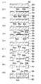
例えば、粒径100nm(0.1μm)の粒子を用いた場合の流路幅(チャンネル幅)と比界面積および拡散時間との関係は、図1に示したようになる。
【0009】
つまり、マイクロスケール空間では、機械的攪拌などを用いなくても、分子輸送、反応、分離が、分子・粒子の自発的挙動だけで速やかに行われる。
【0010】
一方、現状のマクロスケールの装置では、直径5mm前後の試験管等を使って、機械式による乱流混合が―般的に行われているが、マイクロスケールになるとマクロスケールに比べて、毛細管力、流路抵抗の影響により、見かけ上、液体の粘度が急増し、液は容易には動かなくなる。
【0011】
例えば、円筒状のマクロ流路とマイクロ流路での混合に必要な機械的攪拌力を比較するため、
必要機械攪拌力=毛細管力(△P)×流路抵抗(△R) ………(2)
△P=H×cosθ×τ/A ………(3)
(ただし、H:液体の表面張力、θ:接触角、τ:流路断面外周長、A:流路断面積)
△R=32×μ×L/π×r4 ………(4)
(ただし、μ:粘度、L:流路長(軸方向の高さ)、r:流路断面半径)
としたモデルを用いると、
内径0.2mmのマイクロ流路内に高さ0.1mmの液体が入っている場合の必要機械攪拌力は、内径5mmのマクロ流路内に高さ2mmの液体が入っている場合の必要機械攪拌力の488281倍となる。つまり、現状のマクロスケールの装置と同じ機械攪拌で同じ程度の混合を達成させるためには、マイクロ流路の場合には、約十万倍の攪拌力が必要となることが、上記モデル計算から導かれる。
【0012】
以上のことから、マイクロスケール空間では、機械的攪拌はマイクロであるが故にデメリットとなるので、機械的攪拌を用いずに、分子・粒子の自発的挙動による拡散を積極的に利用して、分子輸送、反応、分離を行うことが考えられる。
【0013】
しかし、拡散時間を効率的に速くしようと流路幅を極端に小さくしてしまうと、流路抵抗が極端に大きくなり、送液の制御ができないばかりか、送液のために非常に大きな圧力が必要となり、送液機構が大型化してしまい、全体としてはマイクロシステムにはならない。また、流路幅が極端に小さいと、液体量が極端に少なく、検出限界が下がり、より高感度な検出機構が必要となり、現在の検出方法ではアプリケーシヨンが限られる。
【0014】
したがって、本発明が解決しようとする技術的課題は、微小領域で効率よく拡散混合を行うことができる混合方法、混合機構、該混合機構を備えたマイクロミキサーおよびマイクロチップを提供することである。
【0015】
【課題を解決するための手段および作用・効果】
本発明は、上記技術的課題を解決するために、以下の構成の混合機構を提供する。
【0016】
混合流路は、一つの第1流路と、複数の第1分岐流路と、1又は2以上の第2分岐流路と、1又は2以上の第2流路と、一つの混合流路とを備える。上記第1分岐流路は、上記第1流路の端部に接続され、上記第1流路と略同じ方向に延在し、互いに略平行に間隔を設けて層状に形成される。第2分岐流路は、少なくとも上記第1分岐流路の間に層状に形成される。上記第2流路は、上記第1流路および上記第1分岐流路を含む面とは異なる面上に配置され、上記第2分岐流路に接続される。上記混合流路は、その端部に、上記第1分岐流路および上記第2分岐流路が交互にそれぞれの層の厚み方向に隣接し合った状態で接続される。上記第1および第2分岐流路は、上記第1および第2分岐流路の厚み方向に中央側の方が外側よりも該厚み方向の寸法が小さい。
【0017】
上記構成において、例えば、第1の液体が第1流路から第1分岐流路へと流れ、第2の液体が第2流路から第2分岐流路へと流れ、第1および第2の流体が混合流路で合流する。第1分岐流路と第2分岐流路を層状に形成することにより、混合流路内において、層状の第1の液体と第2の液体とが交互に流れ、第1の液体と第2の液体との間で拡散混合を行うようにすることができる。例えば、第1の液体又は第2の液体のいずれか一方に含まれる分子・粒子が、ブラウン運動などにより他方に移動するようにすることができる。また、一般に、ポンプ等の機械的手段によって発生した圧力により液体が送液される場合、流路幅が狭ければ狭いほど、流路壁の影響を受けやすく、流路幅方向に速度分布を生じる。具体的には中央部は流路壁付近に比べて流速が大きい。混合流路においては、流速が遅いほど、混合時間が長くなり混合が進行しやすく、また短距離で混合が終了する。そこで、上記構成のように分岐流路幅を変えれば、混合流路に流れ込んだ後の各層の流速を略等しくして、効率よく均一に拡散混合が進むようにすることができる。
【0018】
上記構成によれば、液体の層を薄くし、拡散距離を短くすることによって拡散時間を短縮し、短時間で効率的に拡散混合を行うようにすることができる。このとき、分岐流路を層状に薄くしても幅を大きくして断面積を確保したり、分岐数を増やすなどして、分岐流路での流路抵抗の増大を防ぎ、送液のための大きなポンプを不要とすることができる。また、流速の制御も比較的簡単である。
【0019】
したがって、微小領域で効率よく拡散混合を行うことができる。
【0020】
なお、第1分岐流路の外側に形成された第2分岐流路を含んでもよい。また、第1および第2分岐流路と混合流路との各接続部分は、完全に重なり合った状態であっても、多少離れた状態であってもよい。また、第2流路は第1流路および第1分岐流路と異なる面上に配置され、流路は立体的に構成されるので、2液合流だけでなく、3液以上を同時に合流させることも可能である。例えば、第1の液体が流れる第1流路および第1分岐流路を平面上に形成し、その上方および/又は下方から2以上の液体がそれぞれ流れ込むようにすれば、3以上の液体を同時に合流させることも可能である。
【0021】
好ましくは、上記第2流路と上記第2分岐流路との接続部分又はその近傍部分に、上記第2流路から上記第2分岐流路への流れ方向に見たとき、該流れ方向に垂直な流路断面の面積が拡大するバルブ部を備える。
【0022】
上記構成において、第2流路を流れた液体が、第2流路と第2分岐流路との接続部分又はその近傍部分に達すると、流路断面積が大きくなるので、所定値以下の圧力のとき、液体の先端を接続部分又はその近傍部分で停止させることができる。また、所定値を越える圧力を液体に加えることにより、接続部分又はその近傍部分を越えて第2分岐流路から混合流路へと流し込むことができる。このようなバルブ機能により、タイミングを見計らって液体を合流させることが可能となる。したがって、混合流路に所定比で液体を導くことが容易となる。また、泡の混入が比較的少なくなるように構成することができる。
【0023】
好ましくは、上記混合流路は、断面減少部を含む。上記断面減少部は、上記第1および第2分岐流路の厚み方向(例えば、混合流路が湾曲している場合には、流路直角方向)の流路断面寸法が、上記端部から離れるほど小さくなる。
【0024】
上記構成によれば、所定比をもって混合流路に複数液体を導いた後に徐々に流路を狭めることにより、複数液体が所定比を維持した状態で層を薄くして拡散距離を短くし、混合時間の短縮を図ることができる。
【0025】
好ましくは、上記第1および第2分岐流路は、それぞれ、上記第1および第2分岐流路の厚み方向の寸法が200μm以下である。
【0026】
混合流路における液体の各層の厚さが200μmのとき、機械的な攪拌と同程度の時間で混合することが可能となる。機械的な攪拌と同等又はそれ以上の効率で混合するには、200μm以下とすることが好ましい。
【0027】
なお、液体の各層の厚さを小さくするほど拡散は速くなるが、小さくし過ぎると、流路抵抗が増大し、加工や反応検出なども困難になり、送液機構や検出機構等を含めた全体としての小型化、効率化を図ることができない。したがって、液体の各層の厚さは、10μm以上(好ましくは20μm以上)、50μm以下とするのが、実用的である。
【0030】
好ましくは、上記第1および第2分岐流路と上記混合流路とは、少なくとも互いの接続部分の近傍部分が略同じ方向に延在する。
【0031】
混合流路で液体を合流させるときに外乱や偏向が生じると、部分的に拡散距離が大きくなり、混合が不完全になる領域が生じたり、泡が発生するが、上記構成によれば、混合流路で液体を合流させるときに外乱や偏向が生じないようにすることができるので、拡散距離を十分に予見でき、均一に混合させることができる。すなわち、効率よく混合することができる。
【0040】
さらに、本発明は、上記技術的課題を解決するために、上記各構成の混合機構を備えたマイクロミキサーを提供する。
【0041】
また、本発明は、上記技術的課題を解決するために、上記各構成の混合機構を備えたマイクロチップを提供する。
【0042】
また、本発明は、上記技術的課題を解決するために、以下の混合方法を提供する。
【0043】
混合方法は、第1の液体を互いに略平行に間隔を設けて複数の層に分岐して流す第1ステップと、上記第1の液体の流路を含む面とは異なる面上に第2の液体を流し、上記第1の液体の上記層の間に上記第2の液体を層状に流す第2ステップと、層状の上記第1および第2の液体を交互にそれぞれの層の厚み方向に隣接し合った状態で合流させる第3ステップとを備える。上記第1および第2ステップにおいて、上記第1および第2の液体の各層の厚み方向寸法が、該厚み方向に中央側の方が外側よりも小さい。
【0044】
上記方法によれば、第1の液体と第2の液体とが合流した後、第1の液体と第2の液体との層間で拡散混合を行うようにすることができる。例えば、第1の液体又は第2の液体のいずれか一方に含まれる分子・粒子が、ブラウン運動などにより他方に移動するようにすることができる。
【0045】
上記方法によれば、液体の層を薄くし、拡散距離を短くすることによって拡散時間を短縮し、短時間で効率的に拡散混合を行うようにすることができる。このとき、液体の層を薄くしても幅を大きして断面積を確保したり、層の数を増やすなどして、流路抵抗の増大を防ぎ、送液のための大きなポンプを不要とすることができる。また、流速の制御も比較的簡単である。
【0046】
また、一般に、ポンプ等の機械的手段によって発生した圧力により液体が送液される場合、流路幅が狭ければ狭いほど、流路壁の影響を受けやすく、流路幅方向に速度分布を生じる。具体的には中央部は流路壁付近に比べて流速が大きい。混合流路においては、流速が遅いほど、混合時間が長くなり拡散混合が進行しやすく、また短距離で混合が終了する。そこで、上記のように合流前の液体の各層の厚さを変えれば、合流後の各層の流速を略等しくして、効率よく均一に拡散混合が進むようにすることができる。したがって、微小領域で効率よく拡散混合を行うことができる。
【0047】
また、2液合流だけでなく、3液以上を同時に合流させることも可能である。
【0048】
好ましくは、上記第1および第2ステップの少なくとも一方は、上記第1又は第2の液体を、合流前の所定位置まで流して一旦停止させる流れ停止ステップと、停止させた上記第1又は第2の液体を、所定のタイミングで上記所定位置からさらに流す流れ再開ステップとを含む。
【0049】
上記流れ停止ステップおよび流れ再開ステップにより、タイミングを見計らって液体を合流させることが可能となる。したがって、所定比で液体を混合することが容易となる。また、泡の混入が比較的少なくなる。
【0050】
好ましくは、合流させた上記第1および第2の液体の厚み方向(流路が湾曲している場合には、流路直角方向)の流路寸法を、下流側ほど小さくする第4ステップをさらに含む。
【0051】
上記第4ステップにより、所定比をもって合流した液体の流路を徐々に狭めるので、所定比を維持した状態で各層を薄くし、層間の拡散距離を短くして、混合時間の短縮を図ることができる。
【0052】
好ましくは、上記第3ステップにおいて、上記第1および第2の液体の各層は、それぞれ、厚み方向の寸法が200μm以下の状態で合流させる。
【0053】
液体の各層の厚さが200μm以下であれば、機械的な攪拌よりも短時間で混合することが可能となる。
【0054】
なお、液体の各層の厚さを小さくするほど拡散は速くなるが、小さくし過ぎると、流路抵抗が増大し、加工や反応検出なども困難になり、送液機構や検出機構等を含めた全体としての小型化、効率化を図ることができない。したがって、液体の各層の厚さは、10μm以上(好ましくは20μm以上)、50μm以下とするのが、実用的である。
【0057】
好ましくは、上記第3ステップにおいて、上記第1および第2の液体の各層を略同じ方向に流して合流させる。
【0058】
上記方法によれば、外乱や偏向が生じないようにして液体を合流させることができるので、拡散距離を十分に予見でき、均一に混合させることができる。すなわち、拡散混合を効率的に行うことができる。
【0059】
好ましくは、上記第3ステップにおいて、上記第1および第2の液体の各層を、合流後に略同じ速度となる速度で合流させる。
【0060】
上記方法によれば、合流後の層間で相対的な速度差ができるだけ生じないようにして、一層効率よく混合を行うことができる。
【0066】
好ましくは、上記第3ステップにおいて、上記第1および第2の液体の各層を略同じ方向に流して合流させる。
【0067】
上記方法によれば、外乱や偏向が生じないようにして液体を合流させることができるので、拡散距離を十分に予見でき、均一に混合させることができる。すなわち、拡散混合を効率的に行うことができる。
【0068】
好ましくは、上記第3ステップにおいて、上記第1および第2の液体の各層を、合流後に略同じ速度となる速度で合流させる。
【0069】
上記方法によれば、合流後の層間で相対的な速度差ができるだけ生じないようにして、一層効率よく混合を行うことができる。
【0070】
【発明の実施の形態】
以下、本発明の実施形態について、図2〜図11を参照しながら説明する。
【0071】
まず、本発明の第1実施形態について、図2〜図10を参照しながら説明する。
【0072】
図2〜図10は、血液凝固検査に用いるマイクロチップ2の実施例を示す。
【0073】
図2に示すように、マイクロチップ2内には、3つの流路部10,20,30が立体的に構成されている。検体(血液)を流す第1流路部10の途中に設けた第1および第2合流部13,16に、希釈液を流す第2流路部20と試薬を流す第3流路部30との接続流路26,36が下から合流し、それぞれの下流側の第1および第2混合流路14,17で各液が混合するようになっている。第2流路部20の下側部分22は、その先端24が3つに分岐し、それぞれ接続流路26に接続されている。第3流路部30の下側部分32は、その先端34が3つに分岐し、それぞれ接続流路36に接続されている。
【0074】
例えば、第1流路路部10は、深さ(図2において上下方向の寸法)が約100μmである。幅(図2において水平方向の寸法)は、上流側流路12では、約150μm、混合流路14,17では約300μmである。
【0075】
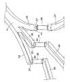
図3の要部拡大斜視図に示したように、第1合流部13には、検体(血液)が流れる3つの第1分岐流路42と、希釈液が流れる3つの第2分岐流路43とが、交互に配置され、その下流側の第1混合流路14において、層状の各液が拡散混合するようになっている。
【0076】
分岐流路42,43を形成するために、第1合流部13には、上流側が接続壁41a,41b,41cでそれぞれ接続された3対の仕切壁40a,40b,40cが配置されている。仕切壁40a,40b,40cは、厚さが数μm程度であり、流路方向に略平行に間隔を設けて配置されている。第1分岐流路42は、仕切壁40a,40b,40cの各対の間に形成され、第1流路部10の上流側流路12から、検体(血液)が流れるようになっている。第2分岐流路43は、仕切壁40a,40b,40cおよび接続壁41a,41b,41cにより断面U字状に形成される。分岐流路43の上流側には接続流路26が接続され、希釈液が流れ込むようになっている。
【0077】
分岐流路42,43の下流側は、混合流路14と平行に延在するように構成され、合流後の液体に外乱や偏向ができるだけ生じないようになっている。これにより、できるだけ均一に液体が混合されるようになっている。
【0078】
仕切壁40a,40b,40cは、等間隔に配置しても、間隔を適宜に変えてもよい。例えば、間隔方向に中央側の方が外側より狭くして、流路42,43の中央側よりも外側の方が、流速が大きくなるようにしてもよい。これにより、混合流路14内において流路壁付近で流速が小さくなるのを防ぎ、各流路42,43から流出した液体の速度が略等しくなるようにして、より均一に混合させることができる。
【0079】
次に、マイクロチップ2の製造工程について、図5を参照しながら説明する。
【0080】
まず、シリコン基板50の上下面に、酸化膜52,54を形成する(図5(1)参照)。シリコン基板50には、例えば厚さ400μmのシリコンウエハーを用いる。酸化膜52,54は、例えば、それぞれの厚さが1.5μmとなるように、熱酸化により成膜する。
【0081】
次に、上面にレジストを塗布し、所定のマスクパターンを露光し、現像する。
そして、上面の酸化膜52をエッチングする。そして、上面のレジストを剥離する(図5(2)参照)。酸化膜52は、符号52a,52bで示したように、その厚さ分を完全に除去する。レジスト塗布には、例えばOFPR800を用い、レジスト膜の厚さは、例えば1μmとする(以下、同じ)。酸化膜52の除去には、例えばRIEを用いる(以下、同じ)。レジストの剥離には、例えば硫酸過水を用いる(以下、同じ)。
【0082】
次に、上面に再びレジストを塗布し、露光、現像を行い、酸化膜52を段状にエッチングする。そして、上面のレジストを剥離する(図5(3)参照)。これにより、符号52cで示したように、酸化膜52を厚さ方向に途中まで除去する。例えば、厚さ0.8μm分だけ除去する。
【0083】
次に、下面にレジストを塗布し、露光、現像し、酸化膜54をエッチングした後、レジストを剥離する(図5(4)参照)。これにより、マスクパターンに従って、符号54aで示したように、酸化膜54を厚さ方向に完全に除去する。
【0084】
次に、上面についてシリコンエッチングを行い、シリコン基板50の貫通孔部分50a,50bを途中まで除去する(図5(5)参照)。シリコンエッチングには、例えば、ICP(高周波誘導結合型プラズマ、Inductively Coupled Plasma)を用いる(以下、同じ)。
【0085】
次に、上面の酸化膜52のエッチングを行ない、段状の薄い部分52cを完全に除去する(図5(6)参照)。さらに、上面についてシリコンエッチングを行い、貫通孔部分50a,50bをさらに深く除去するとともに、上側流路51aを形成する(図5(7)参照)。
【0086】
次に、下面についてシリコンエッチングを行い、貫通孔部分50a,50bを貫通するとともに、下側流路51bを形成する(図5(8)参照)。
【0087】
次に、上下面の酸化膜52,54を剥離し、完全に除去する(図5(9)参照)。酸化膜52,54の剥離には、BHFを用いる。
【0088】
そして、シリコン基板50の両面に、ガラス蓋56,58を貼り付ける(図5(10)参照)。例えば、900V、400°Cで、陽極接合を行う。
【0089】
上側流路51aとしては、図6の上面図に示したように、第1流路部10を形成する。第1流路部10の両端には、開口11,19が形成され、検体を供給し、廃液を排出できるようになっている。
【0090】
第1および第2混合流路14,17は、図6(a)に示したように、流路幅(図において流路と直角方向の寸法)が一定であってもよい。また、図6(b)に示したように、第1および第2混合流路14a,16aの途中に、流路幅が狭くなった断面減少部15,18を設けてもよい。後者の場合には、液体の各層が断面減少部15,18で薄くなり、前者に比べて混合が一層促進される。例えば、界面で部分的に凝固等が生じても、界面が広がるので、均一に混合することができる。流路幅は、例えば約半分程度、狭くする。
【0091】
下側流路51bとしては、図7(a)の下面図に示したように、第2および第3流路部20,30を形成する。下側流路51b、すなわち、第2および第3流路部20,30は、上側流路51a、すなわち第1流路部10の上流側流路12とは逆方向に湾曲し、前述したように、先端部分24,34が3つに分岐している。第2および第3流路部20,30の他端21,31は、シリコン基板50の上面まで貫通し、希釈液および試薬を供給することができるようになっている。
【0092】
上側流路51aと下側流路51bとは、例えば図8の斜視図に示したように、接続流路26を介して接続されている。
【0093】
分岐流路43の下面44には、接続流路26の端部である開口27が形成されている。
【0094】
液体が、接続流路26を通って開口27に達すると、流路断面積が大きくなるので、流体の先端(メニスカス)を開口27で停止させることができる。接続流路26の内面や分岐流路43の下面44が適宜なぬれ性あるいは撥水性を有するようにすると、所定の大きさの圧力(以下、「ストップ力」と呼ぶ)では、流体の先端が開口に留まり、ストップ力より大きい圧力を越えると、流体が開口27から分岐流路43内に流れ込むようにすることができる。
【0095】
図9および図10は、ストップ力と流体の先端の接触角との関係を示すグラフである。図9は、流路断面の幅が40μm、高さが100μmの場合を示す。図10は、流路断面の幅が70μm、高さが100μmの場合を示す。
【0096】
このようなバルブ機能を有する部分(バルブ部)を設けることにより、所定タイミングで送液を行うことができ、したがって、液体の混合比を精度良く制御することができる。
【0097】
なお、流路断面積を不連続に変化させなくても、バルブ機能を持たせることは可能である。また、検体(血液)についても、例えば、上流側流路12の途中に、バルブ機能を有する部分を設けるようにしてもよい。
【0098】
図4は、マイクロチップ2の使用例を示す斜視図である。マイクロチップ2の上下をホルダー4で挟持する。ホルダー4には開口部5が形成され、マイクロチップ2に接続したキャップ4〜7から、液体を注入、排出するようになっている。血液凝固検査の場合には、キャップ4からは検体(血液)を、キャップ5からは希釈液を、キャップ6からは試薬をそれぞれ注入し、キャップ7からは廃液を回収する。
【0099】
次に、本発明の第2実施形態について、図11を参照しながら説明する。
【0100】
マイクロチップ3は、基板60に3つの流路部62,64,66が形成されている。第1および第2流路部62,64は、基板60内で第3流路部66と合流するようになっている。基板60の上面には、第1および第3流路部62,66の一方の端部である開口62a,66aが形成されている。基板60の下面には第2流路部64の一方の端部である開口64aが形成されている。開口62a,64aから供給された2液が第3流路部66で合流し、開口66aから排出されるようになっている。
【0101】
流路部62,64,66の接合部分の近傍部分において、各流路部62,64,66は略同じ方向に延在するように構成され、合流したときに液体に外乱や偏向ができるだけ生じないようになっている。接合部分の近傍部分において、各流路部62,64,66の深さ方向寸法(図11(a)において、上下方向の寸法)を相対的に小さくすることで、第1実施形態と同様に拡散混合を利用して、短時間で2液を混合することができる。一方、各流路部62,64,66の幅方向寸法(図11(a)において、紙面直角方向の寸法)を相対的に大きくすることで、流路抵抗が大きくなり過ぎないようにすることができる。
【0102】
マイクロチップ3は、例えば図11(a)において中央で基板60を上下に分割し、流路部62および66を含む部分と流路部66を含む部分とを接合することにより、形成することができる。このとき、比較的浅い溝を形成して接合すればよいので、ガラスやプラスチックの成型による製造等も可能であり、製造の自由度が増す。
【0103】
なお、例えば図11(a)において鎖線で示したように、第3流路部66に、第1実施形態と同様、深さが徐々に小さくなる断面減少部67を設けるようにすれば、一層効率よく混合することができる。
【0104】
以上説明した各実施形態は、微小領域で効率よく拡散混合を行うことができる。
【0105】
なお、本発明は上記各実施形態に限定されるものではなく、その他種々の態様で実施可能である。
【0106】
例えば、マイクロチップ2,3は、血液凝固に限らず、微小量の液体を混合するマイクロミキサーの主要構成部として、広く用いることができる。
【図面の簡単な説明】
【図1】 流路幅と拡散時間および比界面積との関係を示す図である。
【図2】 本発明の第1実施形態に係るマイクロチップの流路構成を示す透視図である。
【図3】 図2の要部拡大透視図である。
【図4】 マイクロチップの使用状態を示す斜視図である。
【図5】 マイクロチップの製造工程の説明図である。
【図6】 マイクロチップの上側流路を示す上面図である。
【図7】 マイクロチップの下側流路を示す下面図である。
【図8】 バルブの説明図である。
【図9】 ストップ力と接触角との関係を示す図である。
【図10】 ストップ力と接触角との関係を示す図である。
【図11】 本発明の第2実施形態のマイクロチップの模式構成図である。
【符号の説明】
2,3 マイクロチップ
10 第1流路部
12 上流側流路(第1流路)
13 第1合流部(第1分岐流路、第2分岐流路)
14,14a 第1混合流路(混合流路、第1流路)
15 断面減少部
16 第2合流部(第1分岐流路、第2分岐流路)
17,17a 第2混合流路(混合流路)
18 断面減少部
20 第2流路部
26 接続流路(第2流路)
27(バルブ部)
30 第3流路部
36 接続流路(第2流路)
42 第1分岐流路
43 第2分岐流路
62 第1流路部(第1分岐流路)
64 第2流路部(第2分岐流路)
66 第3流路部(混合流路)
67 断面減少部[0001]
BACKGROUND OF THE INVENTION
The present invention relates to a mixing method, a mixing mechanism, a micromixer and a microchip having the mixing mechanism.
[0002]
[Prior art]
[mu] -TAS ([mu] -Total Analysis System) is much smaller in size than a flask or test tube that has been used conventionally. Therefore, attention has been paid as one of the features that the amount and cost of reagents and specimens to be used, and disposal can be suppressed, and that minute amounts can be synthesized and detected. μ-TAS can be applied to clinical analysis chips, environmental analysis chips, gene analysis chips (DNA chips), hygiene analysis chips, chemical / biochemical synthesis chips, and the like.
[0003]
For example, Japanese Translation of PCT International Publication No. 2000-512541 discloses an extraction apparatus having a flow path with a width of about 10 μm to about 100 μm. However, there is no disclosure of a micro mixing mechanism in which a plurality of branched flow paths are arranged three-dimensionally and merged in parallel.
[0004]
Further, “LIQIOD-SHEET BRAKEUP IN MICROMIXERS” is disclosed in “Current Status and Prospects of Microreactor Technology”. In this system, a liquid and a gas are flowed in opposite directions on the same plane, merged, and taken out directly above.
[0005]
[Problems to be solved by the invention]
In the world of microchannels where the channel is microscale, both the dimensions and flow velocity are small, and the Reynolds number is 200 or less. For example, when water is flowed at a flow rate of 2 mm / s through an average channel having a width of 200 μm used in the microchannel, the Reynolds number is 0.4. Therefore, in the world of microchannels (channel width of about 500 μm or less), it is not a turbulent flow control as in a conventional reactor, but a laminar flow control world.
[0006]
In the microscale space, the specific interface area is large, which is advantageous for diffusive mixing at the interface where the laminar flow contacts. The time required for mixing depends on the cross-sectional area of the interface between the two liquids and the thickness of the liquid layer.
[0007]
According to the diffusion theory, the time (T) required for mixing is W (W) and diffusion coefficient (D).2Since it is proportional to / D, the smaller the channel width, the faster the mixing (diffusion) time. The diffusion coefficient D is given by the following equation.
D = Kb × T / 6 × π × μ × r (1)
(However, T: liquid temperature, μ: viscosity, r: particle radius, Kb: Boltzmann constant)
[0008]
For example, the relationship between the channel width (channel width), the specific interface area, and the diffusion time when particles having a particle diameter of 100 nm (0.1 μm) are used is as shown in FIG.
[0009]
In other words, in the microscale space, molecular transport, reaction, and separation can be performed quickly only by spontaneous behavior of molecules / particles without using mechanical stirring.
[0010]
On the other hand, in the current macro scale apparatus, mechanical turbulent mixing is generally performed using a test tube having a diameter of about 5 mm. However, in the micro scale, the capillary force is larger than that in the macro scale. The viscosity of the liquid apparently increases due to the influence of the channel resistance, and the liquid does not move easily.
[0011]
For example, in order to compare the mechanical stirring force required for mixing in a cylindrical macro channel and a micro channel,
Necessary mechanical stirring force = Capillary force (△ P) x Channel resistance (△ R) (2)
ΔP = H × cos θ × τ / A (3)
(However, H: surface tension of liquid, θ: contact angle, τ: flow path cross-sectional perimeter, A: flow cross-sectional area)
ΔR = 32 × μ × L / π × r4 ……… (4)
(Where μ: viscosity, L: channel length (axial height), r: channel cross-sectional radius)
Using the model
The required mechanical stirring force when a 0.1 mm high liquid is contained in a 0.2 mm inner diameter micro flow path is required for a 2 mm high liquid contained in a 5 mm inner diameter macro flow path. 488281 times the stirring force. In other words, in order to achieve the same degree of mixing with the same mechanical agitation as the current macro scale device, in the case of the micro flow path, about 100,000 times of agitation force is required. Led.
[0012]
From the above, in the micro-scale space, mechanical stirring is a disadvantage because it is micro, so without using mechanical stirring, the diffusion by the spontaneous behavior of molecules / particles is actively used to Transport, reaction and separation can be considered.
[0013]
However, if the flow path width is made extremely small in order to increase the diffusion time efficiently, the flow resistance becomes extremely large and not only the liquid feeding control is possible, but also a very large pressure for the liquid feeding. Is required, and the liquid feeding mechanism becomes large, and the whole system does not become a micro system. In addition, if the flow path width is extremely small, the amount of liquid is extremely small, the detection limit is lowered, and a more sensitive detection mechanism is required, and the current detection method limits the application.
[0014]
Therefore, the technical problem to be solved by the present invention is to provide a mixing method, a mixing mechanism, a micromixer and a microchip provided with the mixing mechanism, which can efficiently perform diffusion mixing in a minute region.
[0015]
[Means for solving the problems and actions / effects]
In order to solve the above technical problems, the present invention provides a mixing mechanism having the following configuration.
[0016]
The mixing channel is one first channel, a plurality of first branch channels, one or more second branch channels, one or more second channels, and one mixing channel. With. The first branch flow path is connected to an end of the first flow path, extends in substantially the same direction as the first flow path, and is formed in a layered manner with an interval substantially parallel to each other. The second branch flow path is formed in layers between at least the first branch flow paths. The second channel is disposed on a surface different from the surface including the first channel and the first branch channel, and is connected to the second branch channel. The mixing channel has the first branch channel and the second branch channel alternately at the end.Adjacent to each other in the thickness direction of each layerConnected in state.The first and second branch flow paths are smaller in the thickness direction at the center side than in the thickness direction in the thickness direction of the first and second branch flow paths.
[0017]
In the above configuration, for example, the first liquid flows from the first flow path to the first branch flow path, the second liquid flows from the second flow path to the second branch flow path, and the first and second The fluid joins in the mixing channel. By forming the first branch flow path and the second branch flow path in layers, the first liquid and the second liquid in layers flow alternately in the mixing flow path, and the first liquid and the second liquid flow. Diffusion mixing with the liquid can be performed. For example, the molecules / particles contained in either the first liquid or the second liquid can be moved to the other by Brownian motion or the like.In general, when the liquid is sent by pressure generated by mechanical means such as a pump, the narrower the channel width, the more susceptible to the influence of the channel wall, and the velocity distribution in the channel width direction. Arise. Specifically, the flow rate in the central part is larger than that in the vicinity of the flow path wall. In the mixing channel, the slower the flow rate, the longer the mixing time and the easier the mixing proceeds, and the mixing ends at a short distance. Therefore, if the branch flow path width is changed as in the above configuration, the flow velocity of each layer after flowing into the mixing flow path can be made substantially equal so that diffusion mixing can proceed efficiently and uniformly.
[0018]
According to the above configuration, it is possible to reduce the diffusion time by thinning the liquid layer and shortening the diffusion distance, and to efficiently perform diffusion mixing in a short time. At this time, even if the branch channel is thinned in layers, the width is increased to ensure a cross-sectional area, or the number of branches is increased to prevent an increase in channel resistance in the branch channel. Large pumps can be eliminated. Also, the control of the flow rate is relatively simple.
[0019]
Accordingly, diffusion mixing can be performed efficiently in a minute region.
[0020]
A second branch channel formed outside the first branch channel may also be included. Moreover, each connection part of a 1st and 2nd branch flow path and a mixing flow path may be in the state which overlaps completely, or may be in a state some distance apart. In addition, the second flow path is arranged on a different surface from the first flow path and the first branch flow path, and the flow path is configured in a three-dimensional manner, so that not only the two liquid merging but also three liquids or more are merged simultaneously. It is also possible. For example, if the first flow path and the first branch flow path through which the first liquid flows are formed on a plane and two or more liquids flow from above and / or below, respectively, three or more liquids can be simultaneously applied. It is also possible to merge.
[0021]
Preferably, when viewed in the flow direction from the second flow path to the second branch flow path at the connection portion between the second flow path and the second branch flow path or in the vicinity thereof, the flow direction is A valve portion that expands the area of the vertical channel cross section is provided.
[0022]
In the above configuration, when the liquid that has flowed through the second flow path reaches the connection portion between the second flow path and the second branch flow path or a portion in the vicinity thereof, the cross-sectional area of the flow path increases, so that the pressure below a predetermined value. In this case, the liquid tip can be stopped at the connection portion or in the vicinity thereof. Further, by applying a pressure exceeding a predetermined value to the liquid, it is possible to flow from the second branch flow path to the mixing flow path beyond the connection portion or the vicinity thereof. With such a valve function, it is possible to join liquids at an appropriate timing. Therefore, it becomes easy to guide the liquid to the mixing channel at a predetermined ratio. Moreover, it can comprise so that mixing of a bubble may become comparatively few.
[0023]
Preferably, the mixing channel includes a cross-sectionally reduced portion. The cross-sectional reduced portion is formed by the first and second branch flow paths.Thickness directionFor example, when the mixing channel is curved, the channel cross-sectional dimension in the direction perpendicular to the channel decreases as the distance from the end portion increases.
[0024]
According to the above configuration, by introducing a plurality of liquids to the mixing channel with a predetermined ratio and then gradually narrowing the channel, the layers are thinned while the plurality of liquids maintain the predetermined ratio, and the diffusion distance is shortened. Time can be shortened.
[0025]
Preferably, the first and second branch flow paths are respectively the first and second branch flow paths.Thickness directionThe dimension is 200 μm or less.
[0026]
When the thickness of each layer of the liquid in the mixing channel is 200 μm, mixing can be performed in a time comparable to mechanical stirring. In order to mix at an efficiency equal to or higher than that of mechanical stirring, the thickness is preferably 200 μm or less.
[0027]
As the thickness of each layer of liquid decreases, diffusion increases, but if it is too small, the flow resistance increases and processing and reaction detection become difficult, including the liquid feeding mechanism and detection mechanism. Overall size and efficiency cannot be achieved. Therefore, it is practical that the thickness of each liquid layer is 10 μm or more (preferably 20 μm or more) and 50 μm or less.
[0030]
Preferably, the first and second branch flow paths and the mixing flow path extend at least in the vicinity of each other in substantially the same direction.
[0031]
If disturbance or deflection occurs when the liquids are merged in the mixing flow path, the diffusion distance partially increases, resulting in areas where mixing is incomplete or bubbles are generated. Since it is possible to prevent disturbance and deflection when the liquids are merged in the flow path, the diffusion distance can be sufficiently predicted and can be mixed uniformly. That is, it can be mixed efficiently.
[0040]
Furthermore, in order to solve the above technical problem, the present invention provides a micromixer provided with the mixing mechanism of each of the above configurations.
[0041]
In order to solve the above technical problem, the present invention provides a microchip provided with the mixing mechanism of each of the above configurations.
[0042]
The present invention also provides the following mixing method in order to solve the above technical problem.
[0043]
The mixing method includes: a first step for flowing the first liquid by branching into a plurality of layers at intervals substantially parallel to each other; and a second step on a surface different from the surface including the flow path of the first liquid. A second step of flowing a liquid and flowing the second liquid in layers between the layers of the first liquid; and the layered first and second liquids alternatelyAdjacent to each other in the thickness direction of each layerAnd a third step of joining in a state.In the first and second steps, the thickness direction dimension of each layer of the first and second liquids is smaller on the center side in the thickness direction than on the outside.
[0044]
According to the above method, after the first liquid and the second liquid merge, diffusion mixing can be performed between the layers of the first liquid and the second liquid. For example, the molecules / particles contained in either the first liquid or the second liquid can be moved to the other by Brownian motion or the like.
[0045]
According to the above method, it is possible to reduce the diffusion time by thinning the liquid layer and shortening the diffusion distance, and to efficiently perform diffusion mixing in a short time. At this time, even if the liquid layer is thinned, the width is increased to ensure a cross-sectional area, or the number of layers is increased, thereby preventing an increase in flow resistance and eliminating the need for a large pump for liquid feeding. can do. Also, the control of the flow rate is relatively simple.
[0046]
In general, when the liquid is sent by pressure generated by mechanical means such as a pump, the narrower the channel width, the more susceptible to the influence of the channel wall, and the velocity distribution in the channel width direction. Arise. Specifically, the flow rate in the central part is larger than that in the vicinity of the flow path wall. In the mixing channel, the slower the flow rate, the longer the mixing time and the easier the diffusive mixing proceeds, and the mixing ends at a short distance. Therefore, if the thickness of each layer of the liquid before joining is changed as described above, the flow velocity of each layer after joining can be made substantially equal so that diffusion mixing can proceed efficiently and uniformly.Accordingly, diffusion mixing can be performed efficiently in a minute region.
[0047]
Moreover, it is possible to combine not only two liquids but also three liquids or more at the same time.
[0048]
Preferably, at least one of the first and second steps includes a flow stopping step of flowing the first or second liquid to a predetermined position before merging and temporarily stopping, and the stopped first or second step. A flow resumption step of further flowing the liquid from the predetermined position at a predetermined timing.
[0049]
The flow stopping step and the flow resuming step allow the liquids to join at an appropriate timing. Therefore, it becomes easy to mix the liquid at a predetermined ratio. Moreover, mixing of bubbles becomes relatively small.
[0050]
Preferably, the combined first and second liquidsThickness directionA fourth step is further included in which the channel dimension in the direction perpendicular to the channel when the channel is curved is further reduced toward the downstream side.
[0051]
By the fourth step, the flow path of the liquid that has joined at a predetermined ratio is gradually narrowed, so that each layer can be made thin while maintaining the predetermined ratio, and the diffusion distance between the layers can be shortened to shorten the mixing time. it can.
[0052]
Preferably, in the third step, each layer of the first and second liquids isThickness directionAre merged in a state of 200 μm or less.
[0053]
When the thickness of each liquid layer is 200 μm or less, mixing can be performed in a shorter time than mechanical stirring.
[0054]
As the thickness of each layer of liquid decreases, diffusion increases, but if it is too small, the flow resistance increases and processing and reaction detection become difficult, including the liquid feeding mechanism and detection mechanism. Overall size and efficiency cannot be achieved. Therefore, it is practical that the thickness of each liquid layer is 10 μm or more (preferably 20 μm or more) and 50 μm or less.
[0057]
Preferably, in the third step, the layers of the first and second liquids are caused to flow and merge in substantially the same direction.
[0058]
According to the above method, the liquids can be merged without causing disturbance or deflection, so that the diffusion distance can be sufficiently foreseen and uniformly mixed. That is, diffusion mixing can be performed efficiently.
[0059]
Preferably, in the third step, the layers of the first and second liquids are joined at a speed that is substantially the same speed after joining.
[0060]
According to the above method, mixing can be performed more efficiently so that a relative speed difference does not occur as much as possible between the layers after joining.
[0066]
Preferably, in the third step, the layers of the first and second liquids are caused to flow and merge in substantially the same direction.
[0067]
According to the above method, the liquids can be merged without causing disturbance or deflection, so that the diffusion distance can be sufficiently foreseen and uniformly mixed. That is, diffusion mixing can be performed efficiently.
[0068]
Preferably, in the third step, the layers of the first and second liquids are joined at a speed that is substantially the same speed after joining.
[0069]
According to the above method, mixing can be performed more efficiently so that a relative speed difference does not occur as much as possible between the layers after joining.
[0070]
DETAILED DESCRIPTION OF THE INVENTION
Hereinafter, embodiments of the present invention will be described with reference to FIGS.
[0071]
First, a first embodiment of the present invention will be described with reference to FIGS.
[0072]
2-10 shows the Example of the
[0073]
As shown in FIG. 2, three
[0074]
For example, the first
[0075]
As shown in the enlarged perspective view of the main part of FIG. 3, the
[0076]
In order to form the
[0077]
The downstream sides of the
[0078]
The
[0079]
Next, the manufacturing process of the
[0080]
First,
[0081]
Next, a resist is applied to the upper surface, and a predetermined mask pattern is exposed and developed.
Then, the
[0082]
Next, a resist is applied again on the upper surface, exposure and development are performed, and the
[0083]
Next, a resist is applied to the lower surface, exposed and developed, and after etching the
[0084]
Next, silicon etching is performed on the upper surface, and the through-
[0085]
Next, the
[0086]
Next, silicon etching is performed on the lower surface to penetrate the through-
[0087]
Next, the
[0088]
Then, glass covers 56 and 58 are attached to both surfaces of the silicon substrate 50 (see FIG. 5 (10)). For example, anodic bonding is performed at 900V and 400 ° C.
[0089]
As the
[0090]
As shown in FIG. 6A, the first and
[0091]
As the
[0092]
The
[0093]
An
[0094]
When the liquid reaches the
[0095]
9 and 10 are graphs showing the relationship between the stop force and the contact angle at the tip of the fluid. FIG. 9 shows a case where the width of the channel cross section is 40 μm and the height is 100 μm. FIG. 10 shows a case where the width of the channel cross section is 70 μm and the height is 100 μm.
[0096]
By providing such a portion having a valve function (valve portion), liquid feeding can be performed at a predetermined timing, and therefore the liquid mixing ratio can be controlled with high accuracy.
[0097]
It is possible to provide a valve function without changing the flow path cross-sectional area discontinuously. For the specimen (blood), for example, a portion having a valve function may be provided in the middle of the
[0098]
FIG. 4 is a perspective view showing an example of use of the
[0099]
Next, a second embodiment of the present invention will be described with reference to FIG.
[0100]
In the
[0101]
In the vicinity of the joint portion of the
[0102]
The
[0103]
For example, as shown by a chain line in FIG. 11A, if the third
[0104]
Each of the embodiments described above can efficiently perform diffusion mixing in a minute region.
[0105]
In addition, this invention is not limited to said each embodiment, It can implement in another various aspect.
[0106]
For example, the
[Brief description of the drawings]
FIG. 1 is a diagram showing a relationship between a channel width, a diffusion time, and a specific interface area.
FIG. 2 is a perspective view showing a flow channel configuration of the microchip according to the first embodiment of the present invention.
FIG. 3 is an enlarged perspective view of a main part of FIG. 2;
FIG. 4 is a perspective view showing a usage state of the microchip.
FIG. 5 is an explanatory diagram of a microchip manufacturing process.
FIG. 6 is a top view showing an upper channel of the microchip.
FIG. 7 is a bottom view showing the lower channel of the microchip.
FIG. 8 is an explanatory diagram of a valve.
FIG. 9 is a diagram illustrating a relationship between a stop force and a contact angle.
FIG. 10 is a diagram showing a relationship between a stop force and a contact angle.
FIG. 11 is a schematic configuration diagram of a microchip according to a second embodiment of the present invention.
[Explanation of symbols]
A few microchips
10 1st flow path part
12 Upstream channel (first channel)
13 1st junction part (1st branch flow path, 2nd branch flow path)
14, 14a First mixing channel (mixing channel, first channel)
15 Reduced section
16 2nd junction part (1st branch flow path, 2nd branch flow path)
17, 17a Second mixing channel (mixing channel)
18 Reduced section
20 Second channel section
26 Connection channel (second channel)
27 (Valve part)
30 3rd flow path part
36 Connection channel (second channel)
42 First branch flow path
43 Second branch flow path
62 1st channel part (1st branch channel)
64 Second channel section (second branch channel)
66 Third channel section (mixing channel)
67 Reduced section
Claims (13)
Translated fromJapanese該第1流路の端部に接続され、該第1流路と略同じ方向に延在し、互いに略平行に間隔を設けて層状に形成された複数の第1分岐流路と、
少なくとも上記第1分岐流路の間に層状に形成された1又は2以上の第2分岐流路と、
上記第1流路および上記第1分岐流路を含む面とは異なる面上に配置され、上記第2分岐流路に接続された1又は2以上の第2流路と、
その端部に、上記第1分岐流路および上記第2分岐流路が交互にそれぞれの層の厚み方向に隣接し合った状態で接続された一つの混合流路とを備え、
上記第1および第2分岐流路は、上記第1および第2分岐流路の厚み方向に中央側の方が外側よりも該厚み方向の寸法が小さい、混合機構。One first flow path;
A plurality of first branch flow paths connected to an end of the first flow path, extending in substantially the same direction as the first flow path, and formed in layers at intervals substantially parallel to each other;
One or two or more second branch channels formed in a layer between at least the first branch channels;
1 or 2 or more 2nd flow paths which are arrange | positioned on the surface different from the surface containing the said 1st flow path and the said 1st branch flow path, and were connected to the said 2nd branch flow path,
At its end,e Bei a mixing channel of one of the first branch flow path and the second branch flow paths are connected in a stateof each other adjacent to the thickness direction of each layeralternately,
The mixing mechanism in whichthe first and second branch flow paths are smaller inthe thickness direction at the center side than in the thickness direction in the thickness direction of the first and second branch flow paths .
上記第1の液体の流路を含む面とは異なる面上に第2の液体を流し、上記第1の液体の上記層の間に上記第2の液体を層状に流す第2ステップと、
層状の上記第1および第2の液体を交互にそれぞれの層の厚み方向に隣接し合った状態で合流させる第3ステップとを備え、
上記第1および第2ステップにおいて、上記第1および第2の液体の各層の厚み方向寸法が、該厚み方向に中央側の方が外側よりも小さい、混合方法。A first step in which the first liquid is allowed to flow in a plurality of layers at intervals substantially parallel to each other;
A second step of flowing a second liquid on a surface different from the surface including the flow path of the first liquid, and flowing the second liquid in layers between the layers of the first liquid;
E Bei and a third step of merging inthe stateof each other adjacent to the thickness direction of each layer alternately the first and second liquidlayer,
In the first and second steps, the thickness direction dimension of each layer of the first and second liquids is a mixing method inwhich the center side in the thickness direction is smaller than the outside .
上記第1又は第2の液体を、合流前の所定位置まで流して一旦停止させる流れ停止ステップと、
停止させた上記第1又は第2の液体を、所定のタイミングで上記所定位置からさらに流す流れ再開ステップとを含むことを特徴とする、請求項8記載の混合方法。At least one of the first and second steps is
A flow stop step of flowing the first or second liquid to a predetermined position before merging and temporarily stopping the flow;
The mixing method according to claim8 , further comprising a flow resuming step of flowing the stopped first or second liquid further from the predetermined position at a predetermined timing.
Priority Applications (2)
| Application Number | Priority Date | Filing Date | Title |
|---|---|---|---|
| JP2001182217AJP4792664B2 (en) | 2001-06-15 | 2001-06-15 | Mixing method, mixing mechanism, micromixer and microchip having the mixing mechanism |
| US10/171,920US6851846B2 (en) | 2001-06-15 | 2002-06-14 | Mixing method, mixing structure, micromixer and microchip having the mixing structure |
Applications Claiming Priority (1)
| Application Number | Priority Date | Filing Date | Title |
|---|---|---|---|
| JP2001182217AJP4792664B2 (en) | 2001-06-15 | 2001-06-15 | Mixing method, mixing mechanism, micromixer and microchip having the mixing mechanism |
Publications (2)
| Publication Number | Publication Date |
|---|---|
| JP2003001077A JP2003001077A (en) | 2003-01-07 |
| JP4792664B2true JP4792664B2 (en) | 2011-10-12 |
Family
ID=19022364
Family Applications (1)
| Application Number | Title | Priority Date | Filing Date |
|---|---|---|---|
| JP2001182217AExpired - Fee RelatedJP4792664B2 (en) | 2001-06-15 | 2001-06-15 | Mixing method, mixing mechanism, micromixer and microchip having the mixing mechanism |
Country Status (2)
| Country | Link |
|---|---|
| US (1) | US6851846B2 (en) |
| JP (1) | JP4792664B2 (en) |
Families Citing this family (51)
| Publication number | Priority date | Publication date | Assignee | Title |
|---|---|---|---|---|
| JP2003294596A (en)* | 2002-03-29 | 2003-10-15 | Asahi Kasei Corp | Mixing mechanism |
| US7718099B2 (en) | 2002-04-25 | 2010-05-18 | Tosoh Corporation | Fine channel device, fine particle producing method and solvent extraction method |
| JP3873866B2 (en)* | 2002-10-31 | 2007-01-31 | 株式会社島津製作所 | Micro fluid mixer |
| US7189578B1 (en)* | 2002-12-02 | 2007-03-13 | Cfd Research Corporation | Methods and systems employing electrothermally induced flow for mixing and cleaning in microsystems |
| US7485671B2 (en)* | 2003-05-16 | 2009-02-03 | Velocys, Inc. | Process for forming an emulsion using microchannel process technology |
| ATE376451T1 (en)* | 2003-05-16 | 2007-11-15 | Velocys Inc | METHOD FOR GENERATING AN EMULSION BY USING MICROCHANNEL PROCESS TECHNOLOGY |
| JP4431857B2 (en)* | 2003-05-30 | 2010-03-17 | 富士フイルム株式会社 | Micro device |
| JP4407177B2 (en)* | 2003-05-30 | 2010-02-03 | 富士フイルム株式会社 | Reaction method using microreactor |
| DE10333921B4 (en) | 2003-07-25 | 2005-10-20 | Wella Ag | Extraction method using a static micromixer |
| JP4752173B2 (en)* | 2003-08-27 | 2011-08-17 | 東ソー株式会社 | Micro channel structure |
| KR20050062897A (en)* | 2003-12-19 | 2005-06-28 | 한국기계연구원 | Apparatus and method for ultrasonic micromixer with cross-sectional radiation to mixed interface |
| US20050252840A1 (en)* | 2004-05-13 | 2005-11-17 | Eksigent Technologies, Llc | Micromixer |
| EP1944079B1 (en)* | 2004-06-11 | 2012-05-30 | Corning Incorporated | Microstructure designs for optimizing mixing and pressure drop |
| JP2006102649A (en)* | 2004-10-06 | 2006-04-20 | Hitachi Industries Co Ltd | Microfluidic device |
| TWI247626B (en) | 2004-08-06 | 2006-01-21 | Hitachi Ind Co Ltd | Micro fluid chip |
| JP5159018B2 (en)* | 2004-09-06 | 2013-03-06 | 洋太郎 畑村 | Mixing equipment |
| EP1804964A1 (en)* | 2004-10-01 | 2007-07-11 | Velocys Inc. | Multiphase mixing process using microchannel process technology |
| JP2006122736A (en)* | 2004-10-26 | 2006-05-18 | Dainippon Screen Mfg Co Ltd | Channel structure and its manufacturing method |
| EP1830952A2 (en)* | 2004-11-17 | 2007-09-12 | Velocys Inc. | Process for making or treating an emulsion using microchannel technology |
| JP4726806B2 (en) | 2005-01-06 | 2011-07-20 | 日宝化学株式会社 | Method for producing aromatic iodine compound |
| WO2007018298A1 (en)* | 2005-08-09 | 2007-02-15 | Canon Kabushiki Kaisha | Fluid-processing device and fluid-processing method |
| US20070047388A1 (en)* | 2005-08-25 | 2007-03-01 | Rockwell Scientific Licensing, Llc | Fluidic mixing structure, method for fabricating same, and mixing method |
| JP2007252979A (en)* | 2006-03-20 | 2007-10-04 | National Institute Of Advanced Industrial & Technology | Method for producing compound by microreactor, microreactor, and shunt for microreactor |
| JP5030520B2 (en)* | 2006-09-29 | 2012-09-19 | 富士フイルム株式会社 | Fluid mixing method and microdevice |
| US20080237044A1 (en)* | 2007-03-28 | 2008-10-02 | The Charles Stark Draper Laboratory, Inc. | Method and apparatus for concentrating molecules |
| US8292083B2 (en) | 2007-04-19 | 2012-10-23 | The Charles Stark Draper Laboratory, Inc. | Method and apparatus for separating particles, cells, molecules and particulates |
| US7837379B2 (en)* | 2007-08-13 | 2010-11-23 | The Charles Stark Draper Laboratory, Inc. | Devices for producing a continuously flowing concentration gradient in laminar flow |
| JP4946778B2 (en)* | 2007-10-17 | 2012-06-06 | 株式会社日立プラントテクノロジー | Microreactor |
| WO2009069656A1 (en)* | 2007-11-26 | 2009-06-04 | Fujimori Kogyo Co., Ltd. | Microchip and blood monitoring device |
| DE102008009199A1 (en)* | 2008-02-15 | 2009-08-27 | Forschungszentrum Karlsruhe Gmbh | Reaction mixer system for mixing and chemical reaction of at least two fluids |
| EP2095872A1 (en)* | 2008-02-29 | 2009-09-02 | Corning Incorporated | Injector assemblies and microreactors incorporating the same |
| JP2009208052A (en)* | 2008-03-06 | 2009-09-17 | National Institute Of Advanced Industrial & Technology | Micro mixer |
| JP4777383B2 (en)* | 2008-04-28 | 2011-09-21 | 株式会社日立製作所 | Microreactor |
| JP5155800B2 (en)* | 2008-09-29 | 2013-03-06 | 富士フイルム株式会社 | Reaction method and reaction apparatus |
| JP5242330B2 (en)* | 2008-10-15 | 2013-07-24 | 古河電気工業株式会社 | Microreactor introduction tube, method for producing microreactor introduction tube, and microreactor |
| JP2009018311A (en)* | 2008-10-30 | 2009-01-29 | Hitachi Plant Technologies Ltd | Microfluidic chip |
| US9421507B2 (en)* | 2012-04-30 | 2016-08-23 | Oregon State University | Micro-channels, micro-mixers and micro-reactors |
| TWI475226B (en)* | 2012-08-01 | 2015-03-01 | Univ Feng Chia | The apparatus and methodology to carry out biochemical testing on a centrifugal platform using flow splitting techniques |
| WO2017096414A1 (en)* | 2015-12-07 | 2017-06-15 | University Of South Australia | Microfluidic chips and uses thereof |
| CN105664773B (en)* | 2016-01-22 | 2017-09-19 | 苏州汶颢芯片科技有限公司 | Plane passive type micro-mixer |
| US11185830B2 (en) | 2017-09-06 | 2021-11-30 | Waters Technologies Corporation | Fluid mixer |
| JP7448540B2 (en)* | 2019-07-19 | 2024-03-12 | アルプスアルパイン株式会社 | fluid stirring device |
| US11555805B2 (en) | 2019-08-12 | 2023-01-17 | Waters Technologies Corporation | Mixer for chromatography system |
| RU2724254C1 (en)* | 2019-10-07 | 2020-06-22 | Общество С Ограниченной Ответственностью "Научно-Производственная Фирма "Материа Медика Холдинг" | Microfluidic mixing chip |
| CN116134312A (en) | 2020-07-07 | 2023-05-16 | 沃特世科技公司 | Mixer for liquid chromatography |
| EP4179311B1 (en) | 2020-07-07 | 2025-07-30 | Waters Technologies Corporation | Combination mixer arrangement for noise reduction in fluid chromatography |
| EP4217729B1 (en) | 2020-09-22 | 2025-08-13 | Waters Technologies Corporation | Continuous flow mixer |
| RU207370U1 (en)* | 2021-05-16 | 2021-10-25 | Константин Александрович Гусев | A device with a microchannel structure made in volume |
| EP4341681A1 (en) | 2021-05-20 | 2024-03-27 | Waters Technologies Corporation | Equal dispersion split-flow mixer |
| US12303849B2 (en) | 2021-06-09 | 2025-05-20 | Revvity Health Sciences, Inc. | Mixing liquids using an automated liquid handling system |
| CN113751091B (en)* | 2021-09-29 | 2022-10-11 | 苏州卫生职业技术学院 | Microfluidic chip for efficient drug screening |
Family Cites Families (15)
| Publication number | Priority date | Publication date | Assignee | Title |
|---|---|---|---|---|
| NL8602338A (en)* | 1986-09-16 | 1988-04-18 | Hoogovens Groep Bv | GAS MIXER. |
| DE3851458T2 (en)* | 1987-04-08 | 1995-02-09 | Hitachi Ltd | Device with a vaginal flow cell. |
| US5094788A (en)* | 1990-12-21 | 1992-03-10 | The Dow Chemical Company | Interfacial surface generator |
| US5094793A (en)* | 1990-12-21 | 1992-03-10 | The Dow Chemical Company | Methods and apparatus for generating interfacial surfaces |
| DE4416343C2 (en)* | 1994-05-09 | 1996-10-17 | Karlsruhe Forschzent | Static micro mixer |
| DE19536856C2 (en)* | 1995-10-03 | 1997-08-21 | Danfoss As | Micromixer and mixing process |
| DE19541266A1 (en)* | 1995-11-06 | 1997-05-07 | Bayer Ag | Method and device for carrying out chemical reactions using a microstructure lamella mixer |
| DE19541265A1 (en)* | 1995-11-06 | 1997-05-07 | Bayer Ag | Process for the preparation of dispersions and for carrying out chemical reactions with a disperse phase |
| DE19604289C2 (en)* | 1996-02-07 | 1998-04-23 | Danfoss As | Micromixer |
| WO1997047390A1 (en)* | 1996-06-14 | 1997-12-18 | University Of Washington | Absorption-enhanced differential extraction device |
| US6136272A (en)* | 1997-09-26 | 2000-10-24 | University Of Washington | Device for rapidly joining and splitting fluid layers |
| BR9914554A (en)* | 1998-10-13 | 2001-06-26 | Biomicro Systems Inc | Fluid circuit components based on passive fluid dynamics |
| US6524456B1 (en)* | 1999-08-12 | 2003-02-25 | Ut-Battelle, Llc | Microfluidic devices for the controlled manipulation of small volumes |
| JP2001120972A (en)* | 1999-10-21 | 2001-05-08 | Shimadzu Corp | Liquid mixer |
| JP2002361002A (en)* | 2001-06-04 | 2002-12-17 | Minolta Co Ltd | Extraction method and extraction apparatus, and separation method and separation apparatus |
- 2001
- 2001-06-15JPJP2001182217Apatent/JP4792664B2/ennot_activeExpired - Fee Related
- 2002
- 2002-06-14USUS10/171,920patent/US6851846B2/ennot_activeExpired - Fee Related
Also Published As
| Publication number | Publication date |
|---|---|
| US20040011413A1 (en) | 2004-01-22 |
| JP2003001077A (en) | 2003-01-07 |
| US6851846B2 (en) | 2005-02-08 |
Similar Documents
| Publication | Publication Date | Title |
|---|---|---|
| JP4792664B2 (en) | Mixing method, mixing mechanism, micromixer and microchip having the mixing mechanism | |
| US20250033009A1 (en) | Scale-up of microfluidic devices | |
| Vladisavljević et al. | Production of uniform droplets using membrane, microchannel and microfluidic emulsification devices | |
| JP4683066B2 (en) | Liquid mixing mechanism | |
| Günther et al. | Multiphase microfluidics: from flow characteristics to chemical and materials synthesis | |
| CN1678397B (en) | Method and device for fluid dispersion | |
| JP3775305B2 (en) | Liquid mixing mechanism and liquid mixing method | |
| US6877892B2 (en) | Multi-stream microfluidic aperture mixers | |
| US6890093B2 (en) | Multi-stream microfludic mixers | |
| EP2004316B8 (en) | Fluidic droplet coalescence | |
| JP4566456B2 (en) | Trace liquid control mechanism and trace liquid control method | |
| JP5963410B2 (en) | Flow path device and fluid mixing method | |
| JP5065803B2 (en) | Micro liquid weighing apparatus, microchip having the same, and liquid measuring method | |
| WO2009048532A2 (en) | Formation of particles for ultrasound application, drug release, and other uses, and microfluidic methods of preparation | |
| JP2007225438A (en) | Microfluid chip | |
| JP4415944B2 (en) | Liquid mixing mechanism | |
| JP2002346355A (en) | Micro mixer | |
| KR20150105856A (en) | Micro Mixer Using Taylor Gortler Vortex and Manufacturing Method Thereof | |
| US20050213425A1 (en) | Micro-mixer/reactor based on arrays of spatially impinging micro-jets | |
| JP5116112B2 (en) | Fluid mixing apparatus and fluid mixing method | |
| JP2005118634A (en) | Micro mixing device | |
| CN101716485B (en) | Tapered quartz capillary tube-based micro-reactor | |
| JP2007024522A (en) | Micro analysis chip | |
| Günther et al. | Multiphase flow | |
| JP2005127864A (en) | Micro mixing device |
Legal Events
| Date | Code | Title | Description |
|---|---|---|---|
| A711 | Notification of change in applicant | Free format text:JAPANESE INTERMEDIATE CODE: A712 Effective date:20050613 | |
| A621 | Written request for application examination | Free format text:JAPANESE INTERMEDIATE CODE: A621 Effective date:20080425 | |
| A977 | Report on retrieval | Free format text:JAPANESE INTERMEDIATE CODE: A971007 Effective date:20090608 | |
| A131 | Notification of reasons for refusal | Free format text:JAPANESE INTERMEDIATE CODE: A131 Effective date:20100817 | |
| A521 | Written amendment | Free format text:JAPANESE INTERMEDIATE CODE: A523 Effective date:20101014 | |
| TRDD | Decision of grant or rejection written | ||
| A01 | Written decision to grant a patent or to grant a registration (utility model) | Free format text:JAPANESE INTERMEDIATE CODE: A01 Effective date:20110628 | |
| A01 | Written decision to grant a patent or to grant a registration (utility model) | Free format text:JAPANESE INTERMEDIATE CODE: A01 | |
| A61 | First payment of annual fees (during grant procedure) | Free format text:JAPANESE INTERMEDIATE CODE: A61 Effective date:20110711 | |
| R150 | Certificate of patent or registration of utility model | Free format text:JAPANESE INTERMEDIATE CODE: R150 | |
| FPAY | Renewal fee payment (event date is renewal date of database) | Free format text:PAYMENT UNTIL: 20140805 Year of fee payment:3 | |
| S531 | Written request for registration of change of domicile | Free format text:JAPANESE INTERMEDIATE CODE: R313531 | |
| S533 | Written request for registration of change of name | Free format text:JAPANESE INTERMEDIATE CODE: R313533 | |
| R350 | Written notification of registration of transfer | Free format text:JAPANESE INTERMEDIATE CODE: R350 | |
| LAPS | Cancellation because of no payment of annual fees |