JP4790372B2 - Computer system for distributing storage access load and control method thereof - Google Patents
Computer system for distributing storage access load and control method thereofDownload PDFInfo
- Publication number
- JP4790372B2 JP4790372B2JP2005305749AJP2005305749AJP4790372B2JP 4790372 B2JP4790372 B2JP 4790372B2JP 2005305749 AJP2005305749 AJP 2005305749AJP 2005305749 AJP2005305749 AJP 2005305749AJP 4790372 B2JP4790372 B2JP 4790372B2
- Authority
- JP
- Japan
- Prior art keywords
- logical volume
- controller
- disk controller
- pair
- switching
- Prior art date
- Legal status (The legal status is an assumption and is not a legal conclusion. Google has not performed a legal analysis and makes no representation as to the accuracy of the status listed.)
- Expired - Fee Related
Links
Images


Classifications
- G—PHYSICS
- G06—COMPUTING OR CALCULATING; COUNTING
- G06F—ELECTRIC DIGITAL DATA PROCESSING
- G06F9/00—Arrangements for program control, e.g. control units
- G06F9/06—Arrangements for program control, e.g. control units using stored programs, i.e. using an internal store of processing equipment to receive or retain programs
- G06F9/46—Multiprogramming arrangements
- G06F9/50—Allocation of resources, e.g. of the central processing unit [CPU]
- G06F9/5005—Allocation of resources, e.g. of the central processing unit [CPU] to service a request
- G06F9/5027—Allocation of resources, e.g. of the central processing unit [CPU] to service a request the resource being a machine, e.g. CPUs, Servers, Terminals
- G06F9/505—Allocation of resources, e.g. of the central processing unit [CPU] to service a request the resource being a machine, e.g. CPUs, Servers, Terminals considering the load
- H—ELECTRICITY
- H04—ELECTRIC COMMUNICATION TECHNIQUE
- H04L—TRANSMISSION OF DIGITAL INFORMATION, e.g. TELEGRAPHIC COMMUNICATION
- H04L67/00—Network arrangements or protocols for supporting network services or applications
- H04L67/01—Protocols
- H04L67/10—Protocols in which an application is distributed across nodes in the network
- H04L67/1001—Protocols in which an application is distributed across nodes in the network for accessing one among a plurality of replicated servers
- H04L67/1004—Server selection for load balancing
- H04L67/1008—Server selection for load balancing based on parameters of servers, e.g. available memory or workload
- H—ELECTRICITY
- H04—ELECTRIC COMMUNICATION TECHNIQUE
- H04L—TRANSMISSION OF DIGITAL INFORMATION, e.g. TELEGRAPHIC COMMUNICATION
- H04L67/00—Network arrangements or protocols for supporting network services or applications
- H04L67/01—Protocols
- H04L67/10—Protocols in which an application is distributed across nodes in the network
- H04L67/1001—Protocols in which an application is distributed across nodes in the network for accessing one among a plurality of replicated servers
- H04L67/1004—Server selection for load balancing
- H04L67/1012—Server selection for load balancing based on compliance of requirements or conditions with available server resources
- H—ELECTRICITY
- H04—ELECTRIC COMMUNICATION TECHNIQUE
- H04L—TRANSMISSION OF DIGITAL INFORMATION, e.g. TELEGRAPHIC COMMUNICATION
- H04L67/00—Network arrangements or protocols for supporting network services or applications
- H04L67/01—Protocols
- H04L67/10—Protocols in which an application is distributed across nodes in the network
- H04L67/1001—Protocols in which an application is distributed across nodes in the network for accessing one among a plurality of replicated servers
- H04L67/1029—Protocols in which an application is distributed across nodes in the network for accessing one among a plurality of replicated servers using data related to the state of servers by a load balancer
- H—ELECTRICITY
- H04—ELECTRIC COMMUNICATION TECHNIQUE
- H04L—TRANSMISSION OF DIGITAL INFORMATION, e.g. TELEGRAPHIC COMMUNICATION
- H04L67/00—Network arrangements or protocols for supporting network services or applications
- H04L67/01—Protocols
- H04L67/10—Protocols in which an application is distributed across nodes in the network
- H04L67/1001—Protocols in which an application is distributed across nodes in the network for accessing one among a plurality of replicated servers
- H04L67/1031—Controlling of the operation of servers by a load balancer, e.g. adding or removing servers that serve requests
- H—ELECTRICITY
- H04—ELECTRIC COMMUNICATION TECHNIQUE
- H04L—TRANSMISSION OF DIGITAL INFORMATION, e.g. TELEGRAPHIC COMMUNICATION
- H04L67/00—Network arrangements or protocols for supporting network services or applications
- H04L67/01—Protocols
- H04L67/10—Protocols in which an application is distributed across nodes in the network
- H04L67/1097—Protocols in which an application is distributed across nodes in the network for distributed storage of data in networks, e.g. transport arrangements for network file system [NFS], storage area networks [SAN] or network attached storage [NAS]
- G—PHYSICS
- G06—COMPUTING OR CALCULATING; COUNTING
- G06F—ELECTRIC DIGITAL DATA PROCESSING
- G06F2209/00—Indexing scheme relating to G06F9/00
- G06F2209/50—Indexing scheme relating to G06F9/50
- G06F2209/5019—Workload prediction
Landscapes
- Engineering & Computer Science (AREA)
- Computer Networks & Wireless Communication (AREA)
- Signal Processing (AREA)
- General Engineering & Computer Science (AREA)
- Software Systems (AREA)
- Theoretical Computer Science (AREA)
- Computer Hardware Design (AREA)
- Physics & Mathematics (AREA)
- General Physics & Mathematics (AREA)
- Information Retrieval, Db Structures And Fs Structures Therefor (AREA)
Abstract
Description
Translated fromJapanese本願明細書で開示される技術は、一つ以上のストレージシステムを含む計算機システムに関し、特に、ストレージシステムのアクセス負荷の分散に関する。 The technology disclosed in the specification of the present application relates to a computer system including one or more storage systems, and more particularly to distribution of access load of a storage system.
ホスト計算機と一つ以上のストレージシステムとがネットワークを介して接続された計算機システムにおいて、ストレージシステムとホスト計算機との間に複数のアクセス経路(パス)を設け、これらのパスにホスト計算機からのアクセスを分散させる技術が知られている(例えば、特許文献1参照)。このような負荷分散技術によれば、複数のパスにアクセス(I/O)の負荷が分散されるため、特定のパスにアクセスが集中することによる性能低下を防止することができる。さらに、一つのパスに障害が発生した場合、他の正常なパスにアクセスが割り当てられる。このため、パスに障害が発生した場合にもアクセスを継続することができる。
複数のホスト計算機と一つ以上のストレージシステムとがネットワークを介して接続されている環境の下では、複数のホスト計算機が一つのストレージシステムを共有する場合がある。しかし、上記特許文献1が開示する従来の負荷分散技術によれば、ホスト計算機がストレージシステムに対する複数のパスを認識し、これらのパスにアクセスを割り当てることによって負荷を分散する。しかし、ホスト計算機は、他のホスト計算機のストレージシステムに対するアクセスの量を知ることができない。さらに、従来の負荷分散技術では、アクセス負荷に応じて新たにパスを設定し、又は、設定されているパスを解除することができない。このため、計算機システム全体でアクセス負荷を適切に分散することができなかった。 In an environment where a plurality of host computers and one or more storage systems are connected via a network, the plurality of host computers may share one storage system. However, according to the conventional load distribution technique disclosed in
本願で開示する代表的な発明は、複数のホスト計算機、複数のストレージシステム及び管理計算機を備える計算機システムの制御方法であって、前記管理計算機は、前記複数のホスト計算機及び前記複数のストレージシステムと第1ネットワークを介して接続され、前記複数のホスト計算機及び前記複数のストレージシステムは、第2ネットワークによって相互に接続され、前記管理計算機は、前記第1ネットワークに接続される第1インターフェースと、前記第1インターフェースに接続される第1プロセッサと、前記第1プロセッサに接続される第1メモリと、を備え、前記各ホスト計算機は、前記第1ネットワークに接続される第2インターフェースと、前記第2ネットワークに接続される第3インターフェースと、前記第2インターフェース及び前記第3インターフェースに接続される第2プロセッサと、前記第2プロセッサに接続される第2メモリと、を備え、前記各ストレージシステムは、前記第1ネットワークに接続される第4インターフェースと、前記第4インターフェースに接続される第3プロセッサと、前記第3プロセッサに接続される第3メモリと、前記第2ネットワークに接続される一つ以上の第5インターフェースと、前記一つ以上の第5インターフェースに接続される一つ以上のコントローラと、前記ホスト計算機が使用するデータを格納する一つ以上の論理ボリュームと、を備え、前記各コントローラは、前記第5インターフェースに接続される第4プロセッサと、前記第4プロセッサに接続される第4メモリと、を備え、前記複数のストレージシステムは、少なくとも、第1論理ボリュームを備える第1ストレージシステムと、第2論理ボリュームを備える第2ストレージシステムと、を含み、前記第1論理ボリューム及び前記第2論理ボリュームは、前記第1論理ボリュームがコピー元、前記第2論理ボリュームがコピー先となるリモートコピーのペアを形成し、前記方法は、前記第1論理ボリュームが割り当てられている前記コントローラの性能情報が所定の閾値を超えるか否かを所定の時間が経過するごとに判定し、前記第1論理ボリュームが割り当てられている前記コントローラの性能情報が所定の閾値を超えた場合、前記第2ストレージシステムの前記少なくとも一つのコントローラのうちの一つに前記第2論理ボリュームを割り当てたときの性能情報を予測し、前記予測された性能情報が前記所定の閾値を超える場合、前記一つのコントローラ以外のコントローラに前記第2論理ボリュームを割り当てたときの性能情報を予測し、前記予測された性能情報が前記所定の閾値を超えない場合、前記第1論理ボリューム及び前記第2論理ボリュームによって形成される前記ペアの属性が非同期モードであるか否かを判定し、前記ペアの属性が非同期モードである場合、前記ペアの属性を同期モードに変更し、前記ペアが同期状態となった後に、前記第2論理ボリュームを、前記予測された性能情報が前記所定の閾値を超えないと判定されたコントローラに割り当て、前記第1論理ボリュームをコピー先に変更し、前記第2論理ボリュームをコピー元に変更し、前記第1論理ボリュームの前記コントローラへの割り当てを解除し、前記第2論理ボリューム及び当該第2論理ボリュームが割り当てられた前記コントローラの組み合わせによって認識されるデバイスを、前記第1論理ボリューム及び当該第1論理ボリュームが割り当てられていた前記コントローラの組み合わせによって認識されるデバイスと同一のデバイスとして前記第2プロセッサに認識させることを特徴とする。A representative invention disclosed in the present application is amethod for controlling a computer system including a plurality of host computers, a plurality of storage systems, and a management computer. The management computer includes the plurality of host computers and the plurality of storage systems. The plurality of host computers and the plurality of storage systems are connected to each other via a second network, the management computer is connected to the first network, and the management computer is connected to the first network. A first processor connected to the first interface; and a first memory connected to the first processor, wherein each of the host computers includes a second interface connected to the first network; A third interface connected to the network; and the second interface And a second processor connected to the third interface; a second memory connected to the second processor; and each storage system includes a fourth interface connected to the first network; A third processor connected to the fourth interface; a third memory connected to the third processor; one or more fifth interfaces connected to the second network; and the one or more fifth interfaces. One or more controllers connected to the interface, and one or more logical volumes for storing data used by the host computer, each controller including a fourth processor connected to the fifth interface; And a fourth memory connected to the fourth processor, and the plurality of storage systems. The system includes at least a first storage system including a first logical volume and a second storage system including a second logical volume, and the first logical volume and the second logical volume are the first logical volume. Forms a remote copy pair in which the second logical volume is the copy destination and the method determines whether the performance information of the controller to which the first logical volume is allocated exceeds a predetermined threshold Is determined every time a predetermined time elapses, and if the performance information of the controller to which the first logical volume is allocated exceeds a predetermined threshold value, of the at least one controller of the second storage system Predicting performance information when the second logical volume is allocated to one, the predicted If the performance information exceeds the predetermined threshold, the performance information when the second logical volume is allocated to a controller other than the one controller is predicted, and the predicted performance information does not exceed the predetermined threshold. If the pair attribute formed by the first logical volume and the second logical volume is asynchronous mode, the pair attribute is synchronized when the pair attribute is asynchronous mode. After changing to the mode and the pair is in a synchronized state, the second logical volume is assigned to a controller that has been determined that the predicted performance information does not exceed the predetermined threshold, and the first logical volume is assigned Change to the copy destination, change the second logical volume to the copy source, and assign the first logical volume to the controller A device recognized by the combination of the second logical volume and the controller to which the second logical volume is assigned is determined by the combination of the controller to which the first logical volume and the first logical volume are assigned. The second processor is recognized as the same device as the recognized device .
本発明の一形態によれば、計算機システム内に設けられた管理サーバが、複数のホスト計算機からのアクセスによる各パスの負荷を監視し、必要に応じて、パスの追加又は切り替え等を実行する。その結果、ホスト計算機からのアクセスによる負荷が計算機システム全体で適切に分散される。 According to an aspect of the present invention, a management server provided in a computer system monitors the load on each path due to access from a plurality of host computers, and executes addition or switching of a path as necessary. . As a result, the load due to access from the host computer is appropriately distributed throughout the computer system.
以下、本発明の実施の形態を、図面を参照して説明する。 Hereinafter, embodiments of the present invention will be described with reference to the drawings.
図1は、本発明の実施の形態の計算機システムの構成を示すブロック図である。 FIG. 1 is a block diagram showing a configuration of a computer system according to the embodiment of this invention.
本実施の形態の計算機システムは、複数のホスト100、一つの管理サーバ110及び一つ以上のストレージシステム130を備える。図1には、二つのホスト100及び二つのストレージシステム130を示すが、本実施の形態の計算機システムは、三つ以上のホスト100及び三つ以上のストレージシステム130を備えてもよい。 The computer system according to this embodiment includes a plurality of
各ホスト100及び各ストレージシステム130は、ファイバチャネルスイッチ(FC−SW)120によって接続される。さらに、各ホスト100、管理サーバ110及び各ストレージシステム130は、インターネットプロトコル(IP)ネットワーク150によって接続される。 Each
ホスト100は、相互に接続されたCPU101、メモリ102、アダプタ104及びネットワークインターフェース(I/F)105を備える計算機である。 The
CPU101は、メモリ102に格納されたソフトウエアを実行するプロセッサである。 The
メモリ102は、CPU101によって実行されるソフトウエアを格納する。本実施の形態のメモリ102は、少なくとも、オペレーティングシステム(OS)(図示省略)、アプリケーションプログラム(図示省略)及びデバイスリンクマネージャ103を格納する。 The
アプリケーションプログラムは、所定の機能を実現するために実行されるプログラムであり、必要に応じて、ストレージシステム130に格納されたデータに対するアクセス要求(I/O要求)を発行する。I/O要求とは、具体的には、書き込み要求又は読み出し要求である。 The application program is a program executed to realize a predetermined function, and issues an access request (I / O request) for data stored in the
デバイスリンクマネージャ103は、アプリケーションプログラムが発行したアクセス要求を、使用可能なパスに割り当てる処理を実行するソフトウエア(いわゆる交代パス管理ソフトウエア)である。本実施の形態において、「パス」とは、ホスト100から、アクセス要求の対象の論理ボリューム135(後述)に至る、データのアクセス経路である。複数の使用可能なパスがある場合、デバイスリンクマネージャ103は、アクセス負荷が分散するようにパスを選択し、そのパスにI/Oを割り当てる。使用していたパスが、障害の発生等によって使用できなくなった場合、デバイスリンクマネージャ103は、他の使用可能なパスにI/Oを割り当てる。デバイスリンクマネージャ103は、上記のようなパスの選択及び割り当てを実行するプログラム(図示省略)及びそのプログラムが参照する情報(図示省略)等を含む。 The
アダプタ104は、FC−SW120に接続され、FC−SW120を介してストレージ130と通信するインターフェース(いわゆるホストバスアダプタ(HBA))である。ホスト100は、複数のアダプタ104を備えてもよい。 The
ネットワークI/F105は、IPネットワーク150に接続され、IPネットワーク150を介して管理サーバ110及びストレージシステム130と通信する。 The network I / F 105 is connected to the
本実施の形態において、各ホスト100は、ホスト識別子によって識別される。図1に示す「ホスト1」及び「ホスト2」は、それぞれ、ホスト識別子が「1」及び「2」であるホスト100を示す。以下の説明において、ホスト識別子が「1」であるホスト100を単にホスト1、ホスト識別子が「2」であるホスト100を単にホスト2と記載する。 In the present embodiment, each
管理サーバ110は、相互に接続されたCPU111、メモリ112及びネットワークI/F114を備える計算機である。 The
CPU111は、メモリ112に格納されたソフトウエアを実行するプロセッサである。 The CPU 111 is a processor that executes software stored in the memory 112.
メモリ112は、CPU111によって実行されるソフトウエアを格納する。本実施の形態のメモリ112は、少なくとも、ストレージマネージャ113を格納する。ストレージマネージャ113は、アクセス負荷を分散するために、アクセス負荷を監視し、パスの追加又は切り替え等を実行するソフトウエアである。ストレージマネージャ113については、後で詳細に説明する(図2等参照)。 The memory 112 stores software executed by the CPU 111. The memory 112 of this embodiment stores at least the
ネットワークI/F114は、IPネットワーク150に接続され、IPネットワーク150を介してホスト100及びストレージシステム130と通信する。 The network I / F 114 is connected to the
ストレージシステム130は、ホスト100が使用するデータを格納する。具体的には、ストレージシステム130は、ホスト100のアプリケーションプログラムによって書き込まれたデータを格納する。ストレージシステム130は、一つ以上のディスクコントローラ131、一つ以上のポート136、ストレージコントローラ137、ネットワークI/F142及びディスクドライブ(図示省略)を備える。 The
ストレージシステム130は、複数のディスクドライブ(例えば、ハードディスクドライブ)を備えてもよい。これらの複数のディスクドライブがRAID(Redundant Arrays of Inexpensive Disks)を構成してもよい。 The
ディスクドライブの記憶領域は、論理ボリューム135としてホスト100のOSに認識される。言い換えると、ホスト100のOSは、一つの論理ボリューム135を一つの論理的なディスクドライブとして認識する。このため、ホスト100のアプリケーションプログラムは、いずれかの論理ボリューム135を対象として、アクセス要求を発行する。 The storage area of the disk drive is recognized by the OS of the
ストレージシステム130は、ディスクドライブ上に、任意の数の、任意の容量の論理ボリューム135を設定することができる。一つの論理ボリューム135は、複数のディスクドライブの記憶領域によって構成されてもよい。各論理ボリューム135は、少なくとも一つのディスクコントローラ131に割り当てられる。論理ボリューム135がディスクコントローラ131に割り当てられていることは、そのディスクコントローラ131を経由してその論理ボリューム135に至るパスが設定されていることを意味する。すなわち、そのディスクコントローラ131に接続されているホスト100は、そのディスクコントローラ131を経由して、その論理ボリューム135にアクセスすることができる。 The
論理ボリューム135をディスクコントローラ131に割り当てる処理とは、ホスト100がそのディスクコントローラ131を経由してその論理ボリューム135にアクセスできることをそのホスト100及びそのホスト100のデバイスリンクマネージャ103に認識させることを意味する。より具体的には、割り当て処理によって、そのディスクコントローラ131とその論理ボリューム135とを対応付ける割り当て情報、すなわち、ホスト100がそのディスクコントローラ131を経由してその論理ボリューム135にアクセスできることを示す情報が、そのディスクコントローラ131のメモリ133に格納される(図示省略)。 The process of assigning the
これらの割り当て情報が変更された場合、管理サーバ110のホスト・ストレージ接続情報管理テーブル204が更新される。ホスト・ストレージ接続情報管理テーブル204の更新は、管理サーバ110が定期的にストレージシステム130の割り当て情報を参照すること、又は、ストレージシステム130が割り当て情報の変更を管理サーバ110に連絡することによって実現されてもよい。 When the allocation information is changed, the host / storage connection information management table 204 of the
デバイスリンクマネージャ103は、ホスト100に接続されている全てのディスクコントローラ131に対して、アクセス可能な論理ボリューム135を示す情報を問い合わせることによって、ホスト100が論理ボリューム135にアクセスするために使用することができるディスクコントローラ131(それが複数ある場合は、複数のディスクコントローラ131)を認識する。そして、デバイスリンクマネージャ103は、使用できるディスクコントローラ131を経由するいずれかのパス(すなわち、いずれかの使用可能なパス)にI/Oを割り当てる。 The
ディスクコントローラ131は、ストレージシステム130をSAN(後述)に接続するための制御装置である。具体的には、ディスクコントローラ131は、ポート136及びFC−SW120を介してホスト100からのアクセス要求を受信する。そして、ディスクコントローラ131は、受信したアクセス要求に従って、そのディスクコントローラ131に割り当てられている論理ボリューム135にデータを書き込み、又は、その論理ボリューム135からデータを読み出す。 The
図1には三つのディスクコントローラ131を図示するが、これらの構成は同様であるため、二つのディスクコントローラ131の構成については図示を省略する。 Although three
本実施の形態のディスクコントローラ131は、相互に接続されたCPU132、メモリ133及びキャッシュメモリ134を備える。 The
CPU132は、メモリ133に格納されたソフトウエアを実行するプロセッサである。CPU132は、ポート136にも接続される。 The
メモリ133は、CPU132によって実行されるソフトウエアを格納する。本実施の形態のメモリ133は、少なくとも、受信したアクセス要求に従ってデータの書き込み又は読み出しを実行するプログラム(図示省略)を格納する。 The
キャッシュメモリ134は、アクセス速度向上のため、論理ボリューム135に書き込まれるデータ又は論理ボリューム135から読み出されたデータを一時的に格納する。ディスクコントローラ131は、高速なアクセスを要求されない場合、キャッシュメモリ134を備えなくてもよい。 The
ホスト100が論理ボリューム135の特定の領域に対する読み出し要求を発行したとき、キャッシュメモリ134は、その領域から読み出されたデータに加えて、その領域の後に続く領域から読み出されたデータ(すなわち、先読みデータ)を格納してもよい。先読みデータは、まだ読み出し要求の対象になっていないが、これから読み出される可能性がある。特に、論理ボリューム135のデータをバックアップする場合等、データが順次読み出される場合には、先読みデータが読み出される可能性が高い。先読みデータが読み出されるとき、ディスクコントローラ131は、ディスクドライブにアクセスせずに、キャッシュメモリ134に格納された先読みデータをホスト100に応答することによって高速なアクセスを実現する。 When the
ポート136は、FC−SW120に接続されるインターフェースである。ディスクコントローラ131のCPU132は、ポート136及びFC−SW120を介してホスト100と通信することができる。 The
ストレージコントローラ137は、ストレージシステム130の構成情報を管理する制御装置である。図1には二つのストレージコントローラ137を図示するが、これらの構成は同様であるため、一方のストレージコントローラ137の構成については図示を省略する。 The
本実施の形態のストレージコントローラ137は、相互に接続されたCPU138及びメモリ139を備える。 The
CPU138は、メモリ139に格納されたソフトウエアを実行するプロセッサである。CPU138は、ネットワークI/F142にも接続される。 The CPU 138 is a processor that executes software stored in the
メモリ139は、CPU138によって実行されるソフトウエアを格納する。本実施の形態のメモリ139は、少なくとも、ディスクコントローラ131の性能情報を収集するプログラム(図示省略)、コントローラ性能情報140及びボリューム管理情報141を格納する。 The
コントローラ性能情報140は、収集されたディスクコントローラ131の性能情報を含む。ディスクコントローラ131の性能情報とは、後述するように、例えばCPU使用率である。 The
ボリューム管理情報141は、ストレージシステム130内のディスクコントローラ131と論理ボリューム135の構成情報を含む。例えば、ボリューム管理情報141は、ストレージシステム130が備える論理ボリューム135がどのディスクコントローラ131に割り当てられているかを示す割り当て情報を含んでもよい。 The
ネットワークI/F142は、IPネットワーク150に接続される。ストレージコントローラ137のCPU138は、ネットワークI/F142及びIPネットワーク150を介して管理サーバ110と通信することができる。 The network I /
本実施の形態において、各ストレージシステム130は、ストレージシステム識別子によって識別される。図1に示す「ストレージシステム1」及び「ストレージシステム2」は、それぞれ、ストレージシステム識別子が「1」及び「2」であるストレージシステム130を示す。以下の説明において、ストレージシステム識別子が「1」及び「2」であるストレージシステム130を、それぞれ、ストレージシステム1及びストレージシステム2と記載する。 In the present embodiment, each
本実施の形態において、各ディスクコントローラ131は、ディスクコントローラ識別子によって識別される。図1に示す「ディスクコントローラ1」、「ディスクコントローラ2」及び「ディスクコントローラ3」は、それぞれ、ディスクコントローラ識別子が「1」、「2」及び「3」であるディスクコントローラ131を示す。以下の説明において、ディスクコントローラ識別子が「1」、「2」及び「3」であるディスクコントローラ131を、それぞれ、ディスクコントローラ1、ディスクコントローラ2、及び、ディスクコントローラ3と記載する。 In the present embodiment, each
本実施の形態において、各論理ボリューム135は、各ストレージシステム130内で一意の論理ボリューム識別子によって識別される。図1のストレージシステム1は、三つの論理ボリューム135を備える。これらの論理ボリューム135の論理ボリューム識別子は、それぞれ、「1」、「2」及び「3」である。以下の説明において、論理ボリューム識別子が「1」、「2」及び「3」である論理ボリューム135を、それぞれ、VOL1、VOL2及びVOL3と記載する。図1のストレージシステム2は、VOL1及びVOL2なる二つの論理ボリューム135を備える。 In the present embodiment, each
FC−SW120は、複数のポート121を備える。各ポートは、ホスト100のアダプタ104又はストレージシステム130のポート136と接続される。FC−SW120は、ホスト100及びストレージシステム130を相互に接続するストレージエリアネットワーク(SAN)を構成する。本実施の形態のSANにおいては、ファイバーチャネルプロトコル(FCプロトコル)が使用されるが、他のプロトコルが使用されてもよい。 The FC-
図2は、本発明の実施の形態のストレージマネージャ113の説明図である。 FIG. 2 is an explanatory diagram of the
本実施の形態のストレージマネージャ113は、切り替えコントローラ201、性能情報管理テーブル202、ボリューム情報管理テーブル203、ホスト・ストレージ接続状態管理テーブル204及びボリュームペア状態管理テーブル205を含む。切り替えコントローラ201は、CPU111によって実行されるプログラムである。一方、ストレージマネージャ113に含まれる各テーブルは、切り替えコントローラ201によって参照される情報を含む。 The
切り替えコントローラ201は、パスの切り替え及び追加等を実行するプログラムである。切り替えコントローラ201が実行する処理については、後でフローチャートを参照して説明する。 The switching
性能情報管理テーブル202は、ストレージシステム130のディスクコントローラ131の性能情報を管理するテーブルである。具体的には、性能情報管理テーブル202には、各ディスクコントローラ131のアクセス負荷に関する情報が登録される。性能情報管理テーブル202については、後で詳細に説明する(図3参照)。 The performance information management table 202 is a table for managing performance information of the
ボリューム情報管理テーブル203は、ストレージシステム130の論理ボリューム135ごとの性能情報を管理するテーブルである。具体的には、ボリューム情報管理テーブル203には、各論理ボリューム135のアクセス量に関する情報が登録される。ボリューム情報管理テーブル203については、後で詳細に説明する(図4参照)。 The volume information management table 203 is a table for managing performance information for each
ホスト・ストレージ接続状態管理テーブル204は、ホスト100及びストレージシステム130の物理的な構成を管理するテーブルである。具体的には、ホスト・ストレージ接続状態管理テーブル204には、ホスト100とストレージシステム130との物理的な接続に関する情報が登録される。ホスト・ストレージ接続状態管理テーブル204については、後で詳細に説明する(図5参照)。 The host / storage connection status management table 204 is a table for managing the physical configuration of the
ボリュームペア状態管理テーブル205は、ストレージ130間に構成されるリモートコピーのペア(後述)を管理するテーブルである。具体的には、ボリュームペア状態管理テーブル205には、ペアを構成する論理ボリューム135に関する情報が登録される。ボリュームペア状態管理テーブル205については、後で詳細に説明する(図6参照)。 The volume pair status management table 205 is a table for managing remote copy pairs (described later) configured between the
図3は、本発明の実施の形態の性能情報管理テーブル202の説明図である。 FIG. 3 is an explanatory diagram of the performance information management table 202 according to the embodiment of this invention.
性能情報管理テーブル202において、一つの行が一つのディスクコントローラ131に対応する。 In the performance information management table 202, one row corresponds to one
性能情報管理テーブル202は、ストレージ301、ディスクコントローラ302及びCPU使用率303を含む。 The performance information management table 202 includes a
ストレージ301には、各ディスクコントローラ131を備えるストレージシステム130を示す情報が登録される。 Information indicating the
ディスクコントローラ302には、各ディスクコントローラ131を示す情報が登録される。 Information indicating each
CPU使用率303には、各ディスクコントローラ131のCPU132のCPU使用率を示す情報が登録される。 Information indicating the CPU usage rate of the
図3の例では、ストレージ301、ディスクコントローラ302及びCPU使用率303として、ストレージシステム1、ディスクコントローラ1及び80%が登録されている(行311)。これは、ストレージシステム1のディスクコントローラ1のCPU132のCPU使用率が80%であることを示す。 In the example of FIG. 3,
同様にして、図3の例では、ストレージシステム1、ディスクコントローラ2及び10%が登録され(行312)、さらに、ストレージシステム2、ディスクコントローラ3及び20%が登録されている(行313)。これらは、それぞれ、ストレージシステム1のディスクコントローラ2のCPU132のCPU使用率が10%であり、ストレージシステム2のディスクコントローラ3のCPU132のCPU使用率が20%であることを示す。 Similarly, in the example of FIG. 3,
なお、CPU使用率は、各ストレージシステム130のストレージコントローラ137によって測定され、コントローラ性能情報140としてメモリ139に格納される。ストレージマネージャ113は、定期的にコントローラ性能情報140を参照してCPU使用率303を更新してもよい。 The CPU usage rate is measured by the
本実施の形態では、ディスクコントローラ131の性能情報として、CPU132のCPU使用率を使用する。しかし、ディスクコントローラ131の性能情報として他の指標を使用しても、本発明を実施することができる。使用することができる指標は、例えば、アクセスデータ量(MB/秒)又はアクセス回数(回/秒)である。 In this embodiment, the CPU usage rate of the
図4は、本発明の実施の形態のボリューム情報管理テーブル203の説明図である。 FIG. 4 is an explanatory diagram of the volume information management table 203 according to the embodiment of this invention.
ボリューム情報管理テーブル203において、一つの行が一つのパスに対応する。 In the volume information management table 203, one row corresponds to one path.
ボリューム情報管理テーブル203は、ストレージ401、ディスクコントローラ402、論理ボリューム403及びデータI/O量404を含む。 The volume information management table 203 includes a
ストレージ401には、各パスが経由するディスクコントローラ131を備えるストレージシステム130を示す情報が登録される。 Information indicating the
ディスクコントローラ402には、各パスが経由するディスクコントローラ131を示す情報が登録される。 Information indicating the
論理ボリューム403には、各パスの接続先の論理ボリューム135を示す情報が登録される。 Information indicating the
データI/O量404には、各パスにおける単位時間当たりのデータI/O量、すなわち、単位時間当たりに書き込み又は読み出しをされたデータの量を示す情報が登録される。データI/O量404は、CPU使用率303と同様、ストレージコントローラ137によって測定され、ストレージマネージャ113によって更新されてもよい。 In the data I /
図4の例では、ストレージ401、ディスクコントローラ402、論理ボリューム403及びデータI/O量404として、それぞれ、ストレージシステム1、ディスクコントローラ1、VOL1及び500KB(キロバイト)/秒が登録される(行411)。これは、ストレージシステム1のディスクコントローラ1を経由してVOL1に至るパスが設定され、そのパスにおいて1秒間に500KBのデータI/O(すなわち、書き込み又は読み出し)が実行されていることを示す。 In the example of FIG. 4,
同様にして、ストレージシステム1のディスクコントローラ1を経由してVOL2に至るパスが設定され、そのパスにおいて1秒間に300KBのデータI/Oが実行されている(行412)。ストレージシステム1のディスクコントローラ2を経由してVOL3に至るパスが設定され、そのパスにおいて1秒間に100KBのデータI/Oが実行されている(行413)。ストレージシステム2のディスクコントローラ3を経由してVOL1に至るパスが設定され、そのパスにおいて1秒間に100KBのデータI/Oが実行されている(行414)。ストレージシステム2のディスクコントローラ3を経由してVOL2に至るパスが設定され、そのパスにおいて1秒間に100KBのデータI/Oが実行されている(行415)。 Similarly, a path reaching the
図5は、本発明の実施の形態のホスト・ストレージ接続情報管理テーブル204の説明図である。 FIG. 5 is an explanatory diagram of the host / storage connection information management table 204 according to the embodiment of this invention.
ホスト・ストレージ接続情報管理テーブル204は、ホスト501、ストレージ502、ディスクコントローラ503及び割り当てボリューム504を含む。 The host / storage connection information management table 204 includes a
ホスト501には、各ディスクコントローラ131と物理的に接続されているホスト100を示す情報が登録される。 Information indicating the
ストレージ502には、各ホスト100と物理的に接続されているディスクコントローラ131を備えるストレージシステム130を示す情報が格納される。 The
ディスクコントローラ503には、各ホスト100と物理的に接続されているディスクコントローラ131を示す情報が登録される。 Information indicating the
割り当てボリューム504には、各ディスクコントローラ131に割り当てられている論理ボリューム135、言い換えると、各ディスクコントローラ131を経由するパスの接続先の論理ボリューム135を示す情報が登録される。 In the assigned
図5の例では、ホスト501、ストレージ502及びディスクコントローラ503として、それぞれ、ホスト1、ストレージシステム1及びディスクコントローラ1が登録される。さらに、これらに対応する割り当てボリューム504として、VOL1及びVOL2が登録される(行511)。これは、ホスト1とストレージシステム1のディスクコントローラ1とが物理的に接続されており、ディスクコントローラ1にVOL1及びVOL2が割り当てられていることを示す。言い換えると、ホスト1は、ディスクコントローラ1を経由して、ストレージシステム1のVOL1及びVOL2にアクセスすることができる。 In the example of FIG. 5, the
なお、仮にディスクコントローラ1にいずれの論理ボリューム135も割り当てられていない場合(言い換えると、ディスクコントローラ1を経由するパスが存在しない場合)、割り当てボリューム504は、何も登録されないため、空欄となる。 If no
同様にして、図5の例では、ホスト1とストレージシステム1のディスクコントローラ2とが物理的に接続されており、ディスクコントローラ2にVOL3が割り当てられている(行512)。ホスト1とストレージシステム2のディスクコントローラ3とが物理的に接続されており、ディスクコントローラ3にVOL1及びVOL2が割り当てられている(行513)。 Similarly, in the example of FIG. 5, the
図6は、本発明の実施の形態のボリュームペア状態管理テーブル205の説明図である。 FIG. 6 is an explanatory diagram of the volume pair status management table 205 according to the embodiment of this invention.
ボリュームペア状態管理テーブル205において、一つの行は、リモートコピーのペアに属する一つの論理ボリューム135に対応する。 In the volume pair status management table 205, one row corresponds to one
リモートコピーとは、論理ボリューム135に格納されたデータを、別のストレージシステム130内の論理ボリューム135にコピーすることによって、これらの二つの論理ボリューム135に同一のデータを格納する技術である。これらの論理ボリューム135を格納する二つのストレージシステム130が地理的に隔離していれば、一方の論理ボリューム135のデータが災害等によって消失した場合にも、計算機システムは、もう一方の論理ボリューム135のデータを使用して業務を継続することができる。 Remote copy is a technique for storing the same data in these two
リモートコピーのペアとは、コピー元の論理ボリューム135とコピー先の論理ボリューム135との組を意味する。以下、コピー元の論理ボリューム135を正論理ボリューム、コピー先の論理ボリューム135を副論理ボリュームと記載する。 The remote copy pair means a set of a copy source
通常、ホスト100は正論理ボリュームにアクセス要求を発行する。また、データの一貫性を維持するため、ホスト100から副論理ボリュームへのデータの書き込みは禁止される。 Normally, the
ボリュームペア状態管理テーブル205は、ID601、ストレージ602、論理ボリューム603、正/副604及びペアボリュームID605を含む。 The volume pair status management table 205 includes an
ID601には、ペアに属する論理ボリューム135を識別するために与えられた識別子が登録される。 Registered in the
ストレージ602には、ペアに属する論理ボリューム135を格納するストレージシステム130を示す情報が登録される。 Information indicating the
論理ボリューム603には、ペアに属する論理ボリューム135を示す情報が登録される。 Information indicating the
正/副604には、ペアに属する論理ボリューム135が正論理ボリューム又は副論理ボリュームのいずれであるかを示す情報が登録される。 In the primary / secondary 604, information indicating whether the
ペアボリュームID605には、論理ボリューム135が属するペアのもう一方の論理ボリューム135を示す情報が登録される。具体的には、そのもう一方の論理ボリューム135に対応するID601の値が登録される。以下、論理ボリューム135がペアに属する場合、そのペアに属するもう一方の論理ボリューム135をペアボリュームと記載する。言い換えると、正論理ボリュームのペアボリュームは、その正論理ボリュームが属するペアの副論理ボリュームであり、副論理ボリュームのペアボリュームは、その副論理ボリュームが属するペアの正論理ボリュームである。 In the
図6の例では、ID601、ストレージ602、論理ボリューム603、正/副604及びペアボリュームID605として、それぞれ、1、ストレージシステム1、VOL1、正、及び、2が登録される(行611)。これは、ストレージシステム1のVOL1が一つのペアに属し、そのペアにおいてそのVOL1が正論理ボリュームであり、そのVOL1にID601として「1」が与えられており、そのVOL1が属するペアのもう一方の論理ボリューム135に与えられたID601が「2」であることを意味する。 In the example of FIG. 6, 1,
さらに、図6の例では、ID601、ストレージ602、論理ボリューム603、正/副604及びペアボリュームID605として、それぞれ、2、ストレージシステム2、VOL2、副、及び、1が登録される(行612)。これは、ストレージシステム2のVOL2が一つのペアに属し、そのペアにおいてそのVOL2が副論理ボリュームであり、そのVOL2にID601として「2」が与えられており、そのVOL2が属するペアのもう一方の論理ボリューム135に与えられたID601が「1」であることを意味する。 Furthermore, in the example of FIG. 6, 2,
行611及び行612は、結局、ストレージシステム1のVOL1とストレージシステム2のVOL2がペアを形成し、そのペアにおいて、VOL1が正論理ボリューム、VOL2が副論理ボリュームであることを意味する。この場合、ホスト100はVOL1のみにアクセス要求を発行し、VOL1のデータがVOL2にコピーされる。ホスト100からVOL2に対するデータの書き込みは禁止される。 The
次に、本実施の形態の切り替えコントローラ201が実行する処理について説明する。 Next, processing executed by the switching
なお、既に説明したように、切り替えコントローラ201は、CPU111によって実行されるプログラムである。したがって、以下の説明において切り替えコントローラ201が実行する処理は、実際には、CPU111によって実行される。 As already described, the switching
最初に、各処理の前提となるディスクコントローラ131への論理ボリューム135の割り当てについて説明する。 First, allocation of the
図7は、本発明の実施の形態のディスクコントローラ131への論理ボリューム135の割り当て処理の説明図である。 FIG. 7 is an explanatory diagram of a process of assigning the
なお、図7は、図1の計算機システムの構成のうち、一つのホスト100及び一つのストレージシステム130のみを示す。図1の構成のうち、割り当て処理の説明に必要ない部分については、図7において図示を省略する。 FIG. 7 shows only one
図7Aは、ディスクコントローラ131に論理ボリューム135が割り当てられる前のストレージシステム130を示す。この場合、ホスト100からVOL1に至るパスが設定されていないため、ホスト100は、ディスクコントローラ1及びディスクコントローラ2のいずれを経由してもVOL1にアクセスすることができない。 FIG. 7A shows the
図7Bは、ディスクコントローラ131に論理ボリューム135が割り当てられた後のストレージシステム130を示す。図7Bの例では、ディスクコントローラ1及びディスクコントローラ2の両方にVOL1が割り当てられる。この場合、ホスト100からディスクコントローラ1を経由してVOL1に至るパス、及び、ホスト100からディスクコントローラ2を経由してVOL1に至るパスが設定されている。このため、ホスト1は、ディスクコントローラ1及びディスクコントローラ2のいずれを経由してもVOL1にアクセスすることができる。FIG. 7B shows the
図7は、VOL1をディスクコントローラ1及びディスクコントローラ2の両方に割り当てる例を示すが、VOL1は、ディスクコントローラ1又はディスクコントローラ2の一方のみに割り当てられてもよい。 FIG. 7 shows an example in which VOL1 is assigned to both the
図8は、本発明の実施の形態の切り替えコントローラ201が実行する割り当て見直し実行判定処理のフローチャートである。 FIG. 8 is a flowchart of assignment review execution determination processing executed by the switching
割り当て見直し実行判定処理は、発生したイベントをチェックして、ディスクコントローラ131への論理ボリューム135の割り当てを見直すか否か(具体的には、後述する割り当て見直し処理を実行するか否か)を判定する処理である。本実施の形態において、割り当てを見直す契機となるイベントは、ストレージシステム130からアラートを受信したこと、又は、前回の見直しから所定の時間が経過したことである。 The allocation review execution determination process checks the event that has occurred, and determines whether to review the allocation of the
例えば、ストレージシステム130のストレージコントローラ137が各ディスクコントローラ131におけるCPU使用率を測定し、いずれかのディスクコントローラ131においてCPU使用率が所定の閾値を超えた場合、IPネットワーク150を介して管理サーバ110にアラートを送信してもよい。一方、管理サーバ110は、タイマ(図示省略)を備えてもよい。そのタイマは、割り当てを見直した後の経過時間を測定し、経過時間が所定の閾値を超えたときに、所定の時間が経過したことを切り替えコントローラ201に通知してもよい。 For example, when the
なお、以下の説明において、管理サーバ110がホスト100又はストレージ130に対して指示又はデータ等を送受信する場合、その送受信はネットワークI/F114及びIPネットワーク150を介して実行される。図9以降の処理についても同様である。 In the following description, when the
切り替えコントローラ201は、最初に、イベントをチェックする(801)。 The switching
次に、切り替えコントローラ201は、イベントの種類を判定する(802)。具体的には、切り替えコントローラ201は、イベントがストレージシステム130から送信されたアラートであるか、又は、前回の見直しからの所定の時間の経過であるかを判定する。 Next, the switching
ステップ802において、イベントがストレージシステム130からのアラートであると判定された場合、いずれかのディスクコントローラ131においてCPU使用率が所定の閾値を超えている。この場合、そのディスクコントローラ131にアクセス負荷が集中していると考えられる。この場合、アクセス負荷を分散することによって、性能(例えば、書き込み/読み出し要求に対する応答時間)が改善される可能性がある。この場合、切り替えコントローラ201は、全てのストレージシステム130から、性能情報を取得する(803)。具体的には、切り替えコントローラ201は、各ストレージコントローラ137のメモリ139に格納されたコントローラ性能情報140を参照して、少なくとも、各CPU132のCPU使用率を取得する。そして、切り替えコントローラ201は、取得したCPU使用率をCPU使用率303として性能情報管理テーブル202に登録する。 If it is determined in
次に、切り替えコントローラ201は、割り当て見直し処理を実行する(806)。割り当て見直し処理については、後で詳細に説明する(図9参照)。 Next, the switching
切り替えコントローラ201は、ステップ806において割り当て見直し処理を実行した後、次回のイベントをチェックするため、ステップ801に戻る。 The switching
一方、ステップ802において、イベントが所定の時間の経過であると判定された場合、前回割り当て見直し処理が実行された時点でアクセス負荷が適切に分散されていたとしても、その後所定の時間が経過する間に、アクセス負荷に偏りが生じている可能性がある。このため、切り替えコントローラ201は、割り当て見直し処理を実行する必要があるか否かを判定する。 On the other hand, if it is determined in
具体的には、切り替えコントローラ201は、全てのストレージシステム130から、性能情報を取得する(804)。ステップ804の処理は、ステップ803の処理と同様である。 Specifically, the switching
次に、切り替えコントローラ201は、性能情報管理テーブル202を参照し、いずれかのディスクコントローラ302に対応するCPU使用率303が所定の閾値を超えているか否かを判定する(805)。 Next, the switching
ステップ805において、いずれかのディスクコントローラ302に対応するCPU使用率303が所定の閾値を超えていないと判定された場合、アクセス負荷が適切に分散されているため、割り当て見直し処理を実行する必要がない。この場合、切り替えコントローラ201は、次回のイベントをチェックするため、ステップ801に戻る。 If it is determined in
一方、ステップ805において、いずれかのディスクコントローラ302に対応するCPU使用率303が所定の閾値を超えていると判定された場合、そのディスクコントローラ302が示すディスクコントローラ131にアクセス負荷が集中していると考えられる。この場合、アクセス負荷を分散することによって、性能が改善される可能性がある。このため、切り替えコントローラ201は、割り当て見直し処理を実行し(806)、その後、ステップ801に戻る。 On the other hand, if it is determined in
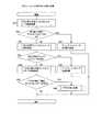
図9は、本発明の実施の形態の切り替えコントローラ201が実行する割り当て見直し処理のフローチャートである。 FIG. 9 is a flowchart of assignment review processing executed by the switching
割り当て見直し処理は、割り当て見直し実行判定処理のステップ806において切り替えコントローラ201によって実行される(図8参照)。 The assignment review process is executed by the switching
切り替えコントローラ201は、最初に、性能情報管理テーブル202を参照して、最もCPU使用率303が高いディスクコントローラ131を検出する(901)。 First, the switching
次に、切り替えコントローラ201は、ホスト・ストレージ接続情報管理テーブル204を参照して、ステップ901において検出されたディスクコントローラ131に割り当てられている論理ボリューム135の一覧表(図示省略)を作成する(902)。 Next, the switching
次に、切り替えコントローラ201は、ボリューム情報管理テーブル203を参照して、一覧表に登録された論理ボリューム135を、検出されたディスクコントローラ131に対するデータI/O量404が多い順に並べ替える。 Next, the switching
次に、切り替えコントローラ201は、一覧表の先頭の論理ボリューム135を対象として(904)、ボリュームごとの割り当て見直し処理を実行する(905)。ボリュームごとの割り当て見直し処理については、後で詳細に説明する(図10参照)。 Next, the switching
次に、切り替えコントローラ201は、ボリュームごとの割り当て見直し処理の戻り値を参照して、論理ボリューム135の割り当てが変更されたか否かを判定する(906)。 Next, the switching
ステップ906において、論理ボリューム135の割り当てが変更されていないと判定された場合、一覧表の次の論理ボリューム135を対象として、ボリュームごとの割り当て見直し処理を実行する(907、904及び905)。一覧表の最後の論理ボリューム135を対象としたボリュームごとの割り当て見直し処理が終了した場合、割り当て見直し処理を終了する。 If it is determined in
一方、ステップ906において、論理ボリューム135の割り当てが変更されたと判定された場合、切り替えコントローラ201は、割り当てが変更された後の各ディスクコントローラの性能を予測し、予測の結果に基づいて、性能情報管理テーブル202及びボリューム情報管理テーブル203を更新する(ステップ908)。さらに、切り替えコントローラ201は、変更された割り当てに従って、ホスト・ストレージ接続情報テーブル204を更新する。後述するペア切り替え処理が実行された場合、切り替えコントローラ201は、さらに、ボリュームペア状態管理テーブル205も更新する。 On the other hand, when it is determined in
次に、切り替えコントローラ201は、更新された性能情報管理テーブル202を参照して、CPU使用率303が所定の閾値を超えているディスクコントローラ131があるか否かを判定する(909)。 Next, the switching
ステップ909において、CPU使用率303が所定の閾値を超えているディスクコントローラ131があると判定された場合、アクセス負荷の偏りが解消されていないため、ステップ901に戻り、割り当て見直し処理を再度実行する。 If it is determined in
一方、ステップ909において、CPU使用率303が所定の閾値を超えているディスクコントローラ131がないと判定された場合、アクセス負荷の偏りが解消された結果、アクセス負荷が適切に分散されている。この場合、割り当て見直し処理を終了する。 On the other hand, if it is determined in
次に、割り当て見直し処理の具体例を説明する。 Next, a specific example of the allocation review process will be described.
例えば、性能情報管理テーブル202が図3に示す通りである場合、ステップ901において、CPU使用率303が最も高い「80%」であるディスクコントローラ1が検出される。 For example, if the performance information management table 202 is as shown in FIG. 3, in
次に、ステップ902において、ホスト・ストレージ接続情報管理テーブル204のディスクコントローラ503及び割り当てボリューム504が参照される。そして、ディスクコントローラ1に割り当てられているVOL1及びVOL2からなる一覧表が作成される。 In
次に、ステップ903において、ボリューム情報管理テーブル203の論理ボリューム403及びデータI/O量404が参照される。そして、データI/O量404が「500KB」であるVOL1が一覧表の先頭に、データI/O量404が「300KB」であるVOL2がVOL1の後に並べられる。 Next, in
次に、ステップ905において、VOL1を対象としてボリュームごとの割り当て見直し処理が実行される。 Next, in
例えば、ステップ905において割り当てが変更された結果、ディスクコントローラ1に割り当てられていたVOL1がディスクコントローラ2に割り当てられた場合、ディスクコントローラ1及びディスクコントローラ2の性能が予測される(908)。具体的には、ディスクコントローラ1及びディスクコントローラ2のCPU132のCPU使用率303が予測される。 For example, if the VOL1 assigned to the
さらに、ステップ908では、性能情報管理テーブル202及びボリューム情報管理テーブル203等が更新される。 In
ステップ909では、更新された性能情報管理テーブル202が参照され、CPU使用率303が所定の閾値を超えるか否かが判定される。 In
図10は、本発明の実施の形態の切り替えコントローラ201が実行するボリュームごとの割り当て見直し処理のフローチャートである。 FIG. 10 is a flowchart of allocation review processing for each volume executed by the switching
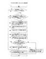
ボリュームごとの割り当て見直し処理は、割り当て見直し処理のステップ905において切り替えコントローラ201によって実行される(図9参照)。 The allocation review process for each volume is executed by the switching
切り替えコントローラ201は、最初に、切り替え可能ディスクコントローラ検索処理を実行する(1001)。 The switching
ディスクコントローラ131の切り替えとは、論理ボリューム135がディスクコントローラ131に割り当てられているとき、その割り当てを解除し、その論理ボリューム135を新たに別のディスクコントローラ131に割り当てることを意味する。例えば、「VOL1をディスクコントローラ2に切り替える」とは、VOL1と他のディスクコントローラ131との割り当てを解除し、VOL1をディスクコントローラ2に新たに割り当てることを意味する。切り替え可能ディスクコントローラ検索処理は、切り替え可能なディスクコントローラ131、すなわち、切り替えによって論理ボリューム135を新たに割り当てることができるディスクコントローラ131を検索する処理である。切り替え可能ディスクコントローラ検索処理については、後で詳細に説明する(図11参照)。 Switching the
次に、切り替えコントローラ201は、切り替え可能ディスクコントローラ検索処理の戻り値を参照して、切り替え可能なディスクコントローラ131があるか否かを判定する(1002)。 Next, the switching
ステップ1002において、切り替え可能なディスクコントローラ131があると判定された場合、切り替えコントローラ201は、ディスクコントローラ切り替え処理を実行して(1004)、ボリュームごとの割り当て見直し処理を終了する。ディスクコントローラ切り替え処理は、論理ボリューム135を、切り替え可能なディスクコントローラ131に切り替える処理である。ディスクコントローラ切り替え処理については、後で詳細に説明する(図14及び図15参照)。 If it is determined in
一方、ステップ1002において、切り替え可能なディスクコントローラ131がないと判定された場合、切り替えコントローラ201は、追加可能ディスクコントローラ検索処理を実行する(1003)。 On the other hand, if it is determined in
ディスクコントローラ131の追加とは、論理ボリューム135がディスクコントローラ131に割り当てられているとき、その割り当てを維持したままで、その論理ボリューム135をさらに別のディスクコントローラ131に割り当てることを意味する。追加可能ディスクコントローラ検索処理は、追加可能なディスクコントローラ131、すなわち、追加によって論理ボリューム135を割り当てることができるディスクコントローラ131を検索する処理である。追加可能ディスクコントローラ検索処理については、後で詳細に説明する(図12参照)。 The addition of the
次に、切り替えコントローラ201は、追加可能ディスクコントローラ検索処理の戻り値を参照して、追加可能なディスクコントローラ131があるか否かを判定する(1005)。 Next, the switching
ステップ1005において、追加可能なディスクコントローラ131があると判定された場合、切り替えコントローラ201は、ディスクコントローラ追加処理を実行して(1007)、ボリュームごとの割り当て見直し処理を終了する。ディスクコントローラ追加処理は、論理ボリューム135を、追加可能なディスクコントローラ131に追加する処理である。ディスクコントローラ追加処理については、後で詳細に説明する(図16及び図17参照)。 If it is determined in
一方、ステップ1005において、追加可能なディスクコントローラ131がないと判定された場合、切り替えコントローラ201は、ペア切り替え可能ディスクコントローラ検索処理を実行する(1006)。 On the other hand, if it is determined in
ペアの切り替えとは、論理ボリューム135がペアに属しているとき、そのペアの正論理ボリュームを副論理ボリュームに、副論理ボリュームを正論理ボリュームに変更することを意味する。ペア切り替え可能ディスクコントローラ検索処理は、ペア切り替え可能なディスクコントローラ131を検索する処理、すなわち、ペアの切り替えをすることができるペアに属する論理ボリューム135が割り当てられたディスクコントローラ131を検索する処理である。ペア切り替え可能ディスクコントローラ検索処理については、後で詳細に説明する(図13参照)。 Pair switching means that when the
次に、切り替えコントローラ201は、ペア切り替え可能ディスクコントローラ検索処理の戻り値を参照して、ペア切り替え可能なディスクコントローラ131があるか否かを判定する(1008)。 Next, the switching
ステップ1008において、ペア切り替え可能なディスクコントローラ131があると判定された場合、切り替えコントローラ201は、ペア切り替え処理を実行して(1009)、ボリュームごとの割り当て見直し処理を終了する。ペア切り替え処理については、後で詳細に説明する(図18及び図19参照)。 If it is determined in
一方、ステップ1008において、ペア切り替え可能なディスクコントローラ131がないと判定された場合、切り替えコントローラ201は、ボリュームごとの割り当て見直し処理を終了する。この場合、ボリュームごとの割り当て見直し処理の戻り値は、論理ボリューム135の割り当てを変更しなかったことを示す値となる。 On the other hand, when it is determined in
一方、ステップ1004、1007又は1009の処理を実行した後でボリュームごとの割り当て見直し処理を終了する場合、戻り値は、論理ボリューム135の割り当てを変更したことを示す値となる。 On the other hand, when the allocation review processing for each volume is terminated after executing the processing of
図11は、本発明の実施の形態の切り替えコントローラ201が実行する切り替え可能ディスクコントローラ検索処理のフローチャートである。 FIG. 11 is a flowchart of the switchable disk controller search process executed by the switching
切り替え可能ディスクコントローラ検索処理は、ボリュームごとの割り当て見直し処理のステップ1001において切り替えコントローラ201に呼び出されて実行される(図10参照)。ボリュームごとの割り当て見直し処理は、割り当て見直し処理のステップ905において実行される(図9参照)。ステップ905において処理の対象とされた論理ボリューム135を、図11の説明において、「当該論理ボリューム135」と記載する。 The switchable disk controller search process is called and executed by the
切り替えコントローラ201は、最初に、ホスト・ストレージ接続情報管理テーブル204を参照して、当該論理ボリューム135、及び、当該論理ボリューム135を使用するホスト100のいずれとも接続可能なディスクコントローラ131の一覧表を作成する(1101)。 First, the switching
次に、切り替えコントローラ201は、性能情報管理テーブル202を参照して、作成した一覧表のディスクコントローラ131を、CPU使用率303が低い順に並べ替える(1102)。 Next, the switching
次に、切り替えコントローラ201は、作成した一覧表の先頭のディスクコントローラ131を対象として(1103)、当該論理ボリューム135がその対象のディスクコントローラ131に既に割り当てられているか否かを判定する(1104)。切り替えコントローラ201は、ステップ1104の判定の際に、ホスト・ストレージ接続情報管理テーブル204を参照する。この判定の対象のディスクコントローラ131を、図11の説明において、「当該ディスクコントローラ131」と記載する。 Next, the switching
ステップ1104において、当該論理ボリューム135が当該ディスクコントローラ131に既に割り当てられていると判定された場合、当該論理ボリューム135をさらに当該ディスクコントローラ131に割り当てることができない。言い換えると、当該論理ボリューム135を当該ディスクコントローラ131に切り替えることができない。この場合、切り替えコントローラ201は、一覧表における次のディスクコントローラ131を対象として、ステップ1104の判定を実行する(1103から1105)。 If it is determined in
一覧表における最後のディスクコントローラ131を対象としたステップ1104の判定が終了した場合、切り替えコントローラ201は、切り替え可能なディスクコントローラ131がないことを、切り替え可能ディスクコントローラ検索処理の呼び出し元に返信して(1106)、切り替え可能ディスクコントローラ検索処理を終了する。言い換えると、この場合、切り替え可能ディスクコントローラ検索処理の戻り値は、切り替え可能なディスクコントローラ131がないことを示す値となる。 When the determination in
一方、ステップ1104において、当該論理ボリューム135が当該ディスクコントローラ131にまだ割り当てられていないと判定された場合、当該論理ボリューム135を当該ディスクコントローラ131に切り替えることができる。ただし、その結果、アクセス負荷が分散されない場合は、切り替えることができない。このため、切り替えコントローラ201は、当該論理ボリューム135を当該ディスクコントローラ131に切り替えた場合のCPU使用率303を予測する(1107)。この予測は、図9のステップ908と同様にして実行されてもよい。 On the other hand, if it is determined in
次に、切り替えコントローラ201は、当該ディスクコントローラ131について予測されたCPU使用率303が所定の閾値を超えているか否かを判定する(1108)。 Next, the switching
ステップ1108において、CPU使用率303の予測値が所定の閾値を超えていると判定された場合、当該論理ボリューム135を当該ディスクコントローラ131に切り替えても、アクセス負荷が分散されないと予想される。したがって、当該論理ボリューム135を当該ディスクコントローラ131に切り替えることができない。 If it is determined in
この時点で、ディスクコントローラ131の一覧表には、まだステップ1104の判定の対象とされていないディスクコントローラ131が残っている場合がある。しかし、ステップ1102において、一覧表のディスクコントローラ131がCPU使用率303の低い順に並べられている。このため、ステップ1108においてアクセス負荷が分散されない場合には、当該論理ボリューム135を残りのディスクコントローラ131に切り替えても、アクセス負荷が分散されないと予想される。このため、切り替えコントローラ201は、切り替え可能なディスクコントローラ131がないことを、切り替え可能ディスクコントローラ検索処理の呼び出し元に返信して(1106)、処理を終了する。 At this time, there may be a case where the
一方、ステップ1108において、CPU使用率303の予測値が所定の閾値を超えていないと判定された場合、当該論理ボリューム135を当該ディスクコントローラ131に切り替えることによって、アクセス負荷が分散されると予想される。このため、切り替えコントローラ201は、当該ディスクコントローラ131が切り替え可能なディスクコントローラであることを切り替え可能ディスクコントローラ検索処理の呼び出し元に返信して(1109)、切り替え可能ディスクコントローラ検索処理を終了する。言い換えると、この場合、切り替え可能ディスクコントローラ検索処理の戻り値は、当該ディスクコントローラ131が切り替え可能なディスクコントローラであることを示す値となる。 On the other hand, if it is determined in
この場合、予測されたCPU使用率303は、図9のステップ908において、性能情報管理テーブル202に登録される。 In this case, the predicted
ここで、切り替え可能ディスクコントローラ検索処理の具体例を説明する。 Here, a specific example of the switchable disk controller search process will be described.
図9のステップ905において、ストレージシステム1のVOL1が処理の対象である場合、そのVOL1が当該論理ボリューム135である。 In
この場合、切り替えコントローラ201は、ホスト・ストレージ接続情報テーブル204を参照する(1101)。その結果、ストレージシステム1のVOL1はホスト1によって使用されている。また、ストレージシステム1は、ディスクコントローラ1及びディスクコントローラ2を備える。ディスクコントローラ2は、ホスト1と物理的に接続されている。このため、切り替えコントローラ201は、ホスト1及びVOL1に接続可能なディスクコントローラ1及びディスクコントローラ2からなる一覧表を作成する。 In this case, the switching
次に、切り替えコントローラ201は、性能情報管理テーブル202を参照する(1102)。ディスクコントローラ2のCPU使用率303「10%」がディスクコントローラ1のCPU使用率303「80%」より低いため、ディスクコントローラ2が一覧表の先頭となる。 Next, the switching
ディスクコントローラ2はVOL1に割り当てられていないため(1104)、切り替えコントローラ201は、VOL1をディスクコントローラ2に切り替えた場合のディスクコントローラ2のCPU使用率303を予測する(1107)。 Since the
予測されたCPU使用率303が所定の閾値を超える場合(1108)、切り替えコントローラ201は、切り替え可能なディスクコントローラ131がないことを返信する(1106)。 When the predicted
一方、予測されたCPU使用率303が所定の閾値を超えない場合(1108)、切り替えコントローラ201は、VOL1をディスクコントローラ2に切り替えることができることを返信する(1109)。この場合、予測されたCPU使用率303は、図9のステップ908において、性能情報管理テーブル202の行312に登録される。 On the other hand, when the predicted
図12は、本発明の実施の形態の切り替えコントローラ201が実行する追加可能ディスクコントローラ検索処理のフローチャートである。 FIG. 12 is a flowchart of addable disk controller search processing executed by the switching
追加可能ディスクコントローラ検索処理は、ボリュームごとの割り当て見直し処理のステップ1003において切り替えコントローラ201に呼び出されて実行される(図10参照)。 The addable disk controller search process is called and executed by the switching
図12に示すように、追加可能ディスクコントローラ検索処理では、ステップ1201からステップ1209までの処理が実行される。これらの処理は、それぞれ、図11のステップ1101からステップ1109までの処理と同様である。 As shown in FIG. 12, in the addable disk controller search process, processes from
ただし、ステップ1207において、切り替えコントローラ201は、当該論理ボリューム135を当該ディスクコントローラ131に追加した場合のCPU使用率303を予測する。この予測は、ステップ1107と同様に実行される。 However, in
ステップ1206において、切り替えコントローラ201は、追加可能なディスクコントローラ131がないことを呼び出し元に返信する。 In
ステップ1206において、切り替えコントローラ201は、当該ディスクコントローラ131が追加可能なディスクコントローラであることを呼び出し元に返信する。 In
その他のステップで実行される処理は、図11に示す処理と同じであるため、説明を省略する。 The processing executed in other steps is the same as the processing shown in FIG.
図13は、本発明の実施の形態の切り替えコントローラ201が実行するペア切り替え可能ディスクコントローラ検索処理のフローチャートである。 FIG. 13 is a flowchart of pair switchable disk controller search processing executed by the switching
ペア切り替え可能ディスクコントローラ検索処理は、ボリュームごとの割り当て見直し処理のステップ1006において切り替えコントローラ201に呼び出されて実行される(図10参照)。 The pair-switchable disk controller search process is called and executed by the
図13の説明において、図11と同様、処理の対象の論理ボリューム135を当該論理ボリューム135と記載する。 In the description of FIG. 13, the
切り替えコントローラ201は、最初に、当該論理ボリューム135にペアボリュームが存在するか否か(言い換えると、当該論理ボリューム135がリモートコピーのペアに属するか否か)を判定する(1301)。 The switching
ステップ1301において、ペアボリュームが存在しないと判定された場合、当該論理ボリューム135がペアに属さないため、当該論理ボリューム135についてペアの切り替えを実行することができない。このため、切り替えコントローラ201は、ペア切り替え可能なディスクコントローラ131がないことをペア切り替え可能ディスクコントローラ検索処理の呼び出し元に返信して(1310)、処理を終了する。言い換えると、この場合、ペア切り替え可能ディスクコントローラ検索処理の戻り値は、ペア切り替え可能なディスクコントローラ131がないことを示す値となる。 If it is determined in
一方、ステップ1301において、ペアボリュームが存在すると判定された場合、当該論理ボリューム135はペアに属する。この場合、切り替えコントローラ201は、当該論理ボリューム135を使用しているホスト100と、当該論理ボリューム135のペアボリュームとを接続可能なディスクコントローラ131が存在するか否かを判定する(1302)。具体的には、切り替えコントローラ201は、ホスト・ストレージ接続情報管理テーブル204を参照して、ペアボリュームが格納されているストレージシステム130のいずれかのディスクコントローラ131が、当該論理ボリューム135を使用するホスト100と物理的に接続されているか否かを判定する。 On the other hand, if it is determined in
ステップ1302において、該当するディスクコントローラ131が存在しないと判定された場合、当該論理ボリューム135を使用するホスト100は、当該論理ボリューム135のペアボリュームにアクセスすることができないため、ペアの切り替えを実行することができない。このため、切り替えコントローラ201は、ステップ1310を実行して処理を終了する。 If it is determined in step 1302 that the
一方、ステップ1302において、該当するディスクコントローラ131が存在すると判定された場合、当該論理ボリューム135を使用するホスト100は、当該論理ボリューム135のペアボリュームにアクセスすることができる。この場合、切り替えコントローラ201は、当該論理ボリューム135を使用しているホスト100と、当該論理ボリューム135のペアボリュームとを接続可能なディスクコントローラ131の一覧表(図示省略)を作成する(1303)。この一覧表を、図13の説明において、「ペア切り替え候補ディスクコントローラ一覧表」と記載する。なお、図13には、ペア切り替え候補ディスクコントローラ一覧表を「一覧表A」と表示する。 On the other hand, if it is determined in step 1302 that the
次に、切り替えコントローラ201は、ペア切り替え候補ディスクコントローラ一覧表に含まれるディスクコントローラ131を、CPU使用率303が低い順に並べ替える(1304)。 Next, the switching
次に、切り替えコントローラ201は、ペア切り替え候補ディスクコントローラ一覧表の先頭のディスクコントローラ131から最後のディスクコントローラ131までを対象として、順に、ステップ1305からステップ1309までのループを実行する。 Next, the switching
最初に、切り替えコントローラ201は、ペア切り替え候補ディスクコントローラ一覧表の先頭のディスクコントローラ131を、ペア切り替え対象ディスクコントローラ一覧表(図示省略)に登録する(1306)。なお、図13には、ペア切り替え対象ディスクコントローラ一覧表を「一覧表B」と表示する。 First, the switching
次に、切り替えコントローラ201は、ペア切り替え対象ディスクコントローラ一覧表に登録されたディスクコントローラ131にペアディスクを割り当てた場合のそのディスクコントローラ131のCPU使用率を予測する(1307)。ペア切り替え対象ディスクコントローラ一覧表に複数のディスクコントローラ131が登録されている場合、それらのディスクコントローラ131のCPU使用率を予測する。この予測は、図9のステップ908と同様に実行されてもよい。 Next, the switching
次に、切り替えコントローラ201は、ペア切り替え対象ディスクコントローラ一覧表に登録されたディスクコントローラ131の中に、予測されたCPU使用率が所定の閾値を超えるものがあるか否かを判定する(1308)。 Next, the switching
ステップ1308において、予測されたCPU使用率が所定の閾値を超えるディスクコントローラ131があると判定された場合、ペアの切り替えによってアクセス負荷が分散されない。この場合、切り替えコントローラ201は、ペア切り替え候補ディスクコントローラ一覧表に登録された次のディスクコントローラ131をペア切り替え対象ディスクコントローラ一覧表に追加して(1306)、ステップ1307及び1308を実行する。 If it is determined in
一方、ステップ1308において、予測されたCPU使用率が所定の閾値を超えるディスクコントローラ131がないと判定された場合、ペアの切り替えによってアクセス負荷が分散される。この場合、切り替えコントローラ201は、ペア切り替え対象ディスクコントローラ一覧表に登録されたディスクコントローラ131をペア切り替え可能なディスクコントローラ131として呼び出し元に返信して(1311)、処理を終了する。言い換えると、この場合、ペア切り替え可能ディスクコントローラ検索処理の戻り値は、ペア切り替え対象ディスクコントローラ一覧表に登録されたディスクコントローラ131がペア切り替え可能なディスクコントローラ131であることを示す値である。 On the other hand, if it is determined in
この場合、予測されたCPU使用率303は、図9のステップ908において、性能情報管理テーブル202に登録される。 In this case, the predicted
ここで、ペア切り替え可能ディスクコントローラ検索処理の具体例を説明する。 Here, a specific example of the pair-switchable disk controller search process will be described.
図6に示すように、ストレージシステム1のVOL1とストレージシステム2のVOL2がペアを形成している場合に、VOL1を当該論理ボリューム135としてペア切り替え可能ディスクコントローラ検索処理を実行する例を説明する。なお、この例の初期状態において、ストレージシステム2のVOL2は、ディスクコントローラ3に割り当てられていない。 As shown in FIG. 6, when VOL1 of the
ストレージシステム1のVOL1のペアボリュームであるストレージシステム2のVOL2が存在する(1301)。すなわち、VOL1はペアに属している。 There is a VOL2 of the
ストレージシステム1のVOL1は、ホスト1によって使用されている。一方、ストレージシステム2に含まれるディスクコントローラ3は、ホスト1と物理的に接続されている(図5参照)(1302)。すなわち、ディスクコントローラ3は、ホスト1及びペアボリュームであるVOL2のいずれとも接続することができる。 The
この例において、ペア切り替え候補ディスクコントローラ一覧表には、ディスクコントローラ3のみが含まれる(1303から1306)。 In this example, the pair switching candidate disk controller list includes only the disk controller 3 (1303 to 1306).
次に、切り替えコントローラ201は、VOL2をディスクコントローラ3に割り当てた場合のディスクコントローラ3のCPU使用率を予測する(1307)。その結果、予測されたCPU使用率が所定の閾値を超えない場合(1308)、切り替えコントローラ201は、ディスクコントローラ3がペア切り替え可能なディスクコントローラ131であることを呼び出し元に返信して(1311)、処理を終了する。この場合、予測されたCPU使用率303は、図9のステップ908において、性能情報管理テーブル202の行313に登録される。 Next, the switching
図14は、本発明の実施の形態の切り替えコントローラ201が実行するディスクコントローラ切り替え処理のフローチャートである。 FIG. 14 is a flowchart of disk controller switching processing executed by the switching
ディスクコントローラ切り替え処理は、ボリュームごとの割り当て見直し処理のステップ1004において切り替えコントローラ201によって実行される(図10参照)。 The disk controller switching process is executed by the switching
図14の説明において、図11と同様、処理の対象の論理ボリューム135を当該論理ボリューム135と記載する。また、ディスクコントローラ切り替え処理が開始された時点で当該論理ボリューム135が割り当てられているディスクコントローラ131を切り替え元ディスクコントローラ131と記載する。さらに、その時点の切り替え可能なディスクコントローラ131を切り替え先ディスクコントローラ131と記載する。 In the description of FIG. 14, the
切り替えコントローラ201は、最初に、当該論理ボリューム131を、切り替え先ディスクコントローラ131に割り当てる(1401)。このとき、切り替えコントローラ201は、当該論理ボリューム131と切り替え先ディスクコントローラ131とを対応付ける割り当て情報を格納する指示をストレージシステム130に送信してもよい。さらに、この割り当てに従って、図9のステップ908においてホスト・ストレージ接続情報管理テーブル204が更新される。 The switching
次に、切り替えコントローラ201は、切り替え元ディスクコントローラ131のキャッシュメモリ134に格納されたデータのうち、当該論理ボリューム135に関するデータを、切り替え先ディスクコントローラ131のキャッシュメモリ134にコピーする(1402)。具体的には、切り替えコントローラ201は、そのデータをコピーする指示をストレージシステム130に送信する。 Next, the switching
当該論理ボリューム135に関するデータとは、当該論理ボリューム135から読み出されるデータ又は当該論理ボリューム135にこれから書き込まれるデータの少なくとも一方である。例えば、切り替え元のキャッシュメモリ134に、当該論理ボリューム135から読み出されたデータ(例えば、先読みデータ)が格納されている場合、そのデータを切り替え先のキャッシュメモリ134にコピーすることによって、切り替えが実行された後も高速なアクセスを実現することができる。The data related to the
なお、コピーが終了した後、コピーされたデータは切り替え元のキャッシュメモリ134から削除されてもよい。 Note that the copied data may be deleted from the switching
次に、切り替えコントローラ201は、当該論理ボリューム135と切り替え元ディスクコントローラ131との割り当てを解除する(1403)。このとき、切り替えコントローラ201は、当該論理ボリューム131と切り替え元ディスクコントローラ131とを対応付ける割り当て情報を削除する指示をストレージシステム130に送信してもよい。さらに、この割り当ての解除に従って、図9のステップ908においてホスト・ストレージ接続情報管理テーブル204が更新される。 Next, the switching
ホスト100のデバイスリンクマネージャ103は、更新された割り当て情報を参照して、切り替え先ディスクコントローラ131を経由して当該論理ボリューム135にアクセスできることを認識する。 The
以上で、ディスクコントローラ切り替え処理が終了する。 This completes the disk controller switching process.
図15は、本発明の実施の形態のディスクコントローラ切り替え処理の具体例の説明図である。 FIG. 15 is an explanatory diagram of a specific example of the disk controller switching processing according to the embodiment of this invention.
図15は、例として、ディスクコントローラ1に割り当てられていたVOL1をディスクコントローラ2に切り替える処理を示す。したがって、図15の例では、VOL1が当該論理ボリューム135、ディスクコントローラ1が切り替え元ディスクコントローラ131、ディスクコントローラ2が切り替え先ディスクコントローラ131に相当する。 FIG. 15 shows a process for switching the
図15(A)は、図14のディスクコントローラ切り替え処理が開始された時点のストレージシステム130を示す。この時点で、VOL1は、ディスクコントローラ1に割り当てられ、ディスクコントローラ2には割り当てられていない。 FIG. 15A shows the
その後、VOL1がディスクコントローラ2に割り当てられる(図14のステップ1401)。次に、ディスクコントローラ1のキャッシュメモリ134に格納されたデータがディスクコントローラ2のキャッシュメモリ134にコピーされる(図14のステップ1402)。次に、VOL1とディスクコントローラ1との割り当てが解除される(図14のステップ1403)。その結果、図15(B)に示すように、VOL1は、ディスクコントローラ2のみに割り当てられる。 Thereafter, VOL1 is assigned to the disk controller 2 (
上記の切り替えの結果、ホスト1からディスクコントローラ2を経由してVOL1に至るパスが追加され、ホスト1からディスクコントローラ1を経由してVOL1に至るパスが削除される。 As a result of the above switching, a path from the
この場合、図9のステップ908において、ホスト・ストレージ接続情報管理テーブル204の行511の割り当てボリューム504からVOL1が削除される。さらに、行512の割り当てボリューム504にVOL1が追加される。 In this case, in
図16は、本発明の実施の形態の切り替えコントローラ201が実行するディスクコントローラ追加処理のフローチャートである。 FIG. 16 is a flowchart of disk controller addition processing executed by the switching
ディスクコントローラ追加処理は、ボリュームごとの割り当て見直し処理のステップ1007において切り替えコントローラ201によって実行される(図10参照)。 The disk controller addition process is executed by the switching
図16の説明において、図11と同様、処理の対象の論理ボリューム135を当該論理ボリューム135と記載する。また、ディスクコントローラ追加処理が開始された時点の追加可能なディスクコントローラ131を追加先ディスクコントローラ131と記載する。In the description of FIG.16 , the
切り替えコントローラ201は、当該論理ボリューム135を、追加先ディスクコントローラ131に割り当てる(1601)。具体的には、切り替えコントローラ201は、当該論理ボリューム135と追加先ディスクコントローラ131とを対応付ける割り当て情報を格納する指示をストレージシステム130に送信してもよい。さらに、この割り当てに従って、図9のステップ908においてホスト・ストレージ接続情報管理テーブル204が更新される。The switching
ホスト100のデバイスリンクマネージャ103は、更新された割り当て情報を参照して、追加元ディスクコントローラ131及び追加先ディスクコントローラ131のいずれを経由しても当該論理ボリューム135にアクセスできることを認識する。The
以上で、ディスクコントローラ追加処理が終了する。 This completes the disk controller addition process.
図17は、本発明の実施の形態のディスクコントローラ追加処理の具体例の説明図である。 FIG. 17 is an explanatory diagram of a specific example of the disk controller addition processing according to the embodiment of this invention.
図17は、例として、ディスクコントローラ1に割り当てられていたVOL1をディスクコントローラ2に追加する処理を示す。したがって、図17の例では、VOL1が当該論理ボリューム135、ディスクコントローラ2が追加先ディスクコントローラ131に相当する。 FIG. 17 shows, as an example, a process of adding
図17(A)は、図16のディスクコントローラ追加処理が開始された時点のストレージシステム130を示す。この時点で、VOL1は、ディスクコントローラ1に割り当てられ、ディスクコントローラ2には割り当てられていない。 FIG. 17A shows the
その後、VOL1がディスクコントローラ2に割り当てられる(図16のステップ1601)。その結果、図17(B)に示すように、VOL1は、ディスクコントローラ1及びディスクコントローラ2の両方に割り当てられる。 Thereafter, VOL1 is assigned to the disk controller 2 (
上記の追加の結果、ホスト1からディスクコントローラ2を経由してVOL1に至るパスが追加される。 As a result of the above addition, a path from the
この場合、図9のステップ908において、ホスト・ストレージ接続情報管理テーブル204の行512の割り当てボリューム504にVOL1が追加される。 In this case, in
図18は、本発明の実施の形態の切り替えコントローラ201が実行するペア切り替え処理のフローチャートである。 FIG. 18 is a flowchart of pair switching processing executed by the switching
ペア切り替え処理は、ボリュームごとの割り当て見直し処理のステップ1009において切り替えコントローラ201によって実行される(図10参照)。 The pair switching process is executed by the switching
最初に、リモートコピーのペアのモードについて説明する。 First, the remote copy pair mode will be described.
リモートコピーのペアの属性には、同期モード及び非同期モードの二つがある。 There are two attributes of the remote copy pair: synchronous mode and asynchronous mode.
ペアが同期モードである場合、ホスト100が正論理ボリュームへのデータの書き込み要求を発行すると、まず、正論理ボリュームに対象のデータが書き込まれる。次に、副論理ボリュームに対象のデータが転送され、書き込まれる。副論理ボリュームへの書き込みが正常に終了すると、ストレージシステム130は、正論理ボリュームにデータが正常に書き込まれたことを示す応答をホスト100に送信する。 When the pair is in the synchronous mode, when the
一方、ペアが非同期モードである場合、ホスト100が正論理ボリュームへのデータの書き込み要求を発行すると、まず、正論理ボリュームに対象のデータが書き込まれる。その後、副論理ボリュームに対象のデータが転送され、書き込まれる。この転送は、正論理ボリュームにデータが書き込まれた直後に実行されてもよいし、正論理ボリュームと拭く論理ボリュームとを結合するデータの経路が混雑していないとき(例えば、夜間)に実行されてもよい。副論理ボリュームへの書き込みが終了したか否かに関らず、ストレージシステム130は、正論理ボリュームにデータが正常に書き込まれたことを示す応答をホスト100に送信する。 On the other hand, when the pair is in the asynchronous mode, when the
なお、各ストレージシステム130は、ペア情報(図示省略)を格納してもよい。ペア情報は、例えば、メモリ133又はメモリ139に格納されてもよい。ペア情報には、例えば、そのストレージシステム130が格納する論理ボリューム135がペアに属するか否かを示す情報、ペアに属する論理ボリューム135が正論理ボリューム又は副論理ボリュームのいずれであるかを示す情報、ペアに属する論理ボリューム135のペアボリュームを識別する情報、及び、ペアのモードを示す情報を含んでもよい。 Each
次に、ペア切り替え処理の手順について説明する。 Next, a procedure for pair switching processing will be described.
図18の説明において、処理の対象の論理ボリューム135が属するペアを当該ペアと記載する。さらに、処理の対象の論理ボリューム135をペア切り替え元ボリュームと記載する。 In the description of FIG. 18, a pair to which the
切り替えコントローラ201は、最初に、当該ペアが非同期モードであるか否かを判定する(1801)。 The switching
ステップ1801において、当該ペアが非同期モードでない(すなわち、同期モードである)と判定された場合、当該ペアの正論理ボリューム及び副論理ボリュームのデータが同期している。この場合、処理はステップ1804に進む。 If it is determined in
一方、ステップ1801において、当該ペアが非同期モードであると判定された場合、当該ペアの正論理ボリューム及び副論理ボリュームのデータが同期していない場合がある。この場合、ペア切り替えを実行する前にデータを同期する必要がある。このため、切り替えコントローラ201は、当該ペアを同期モードに変更する(1802)。このとき、切り替えコントローラ201は、ペア情報として登録されたペアのモードを更新する指示をストレージシステム130に送信してもよい。 On the other hand, if it is determined in
次に、切り替えコントローラ201は、当該ペアが同期状態(すなわち、正論理ボリュームと副論理ボリュームに同一のデータが格納された状態)になるのを待つ(1803)。 Next, the switching
切り替えコントローラ201は、当該ペアが同期状態になると、ホスト100のデバイスリンクマネージャ103に、ペア構成情報を送信する(1804)。ここで、ペア構成情報は、当該ペアの正論理ボリューム及び副論理ボリュームを識別する情報を含む。 When the pair is synchronized, the switching
次に、切り替えコントローラ201は、ペアボリューム(すなわち、当該ペアの副論理ボリューム)を、ペア切り替え可能ディスクコントローラ検索処理のステップ1311(図13参照)において返信されたペア切り替え可能なディスクコントローラ131に割り当てる(1805)。複数のペア切り替え可能なディスクコントローラ131がある場合、切り替えコントローラ201は、それらの複数のペア切り替え可能なディスクコントローラ131にペアボリュームを割り当てる。 Next, the switching
次に、切り替えコントローラ201は、ペア切り替え元ボリュームへのアクセスがなくなるのを待つ(1806)。 Next, the switching
次に、切り替えコントローラ201は、当該ペアを切り替える(1807)。すなわち、当該ペアの正論理ボリュームを副論理ボリュームに変更し、副論理ボリュームを正論理ボリュームに変更する。このとき、切り替えコントローラ201は、当該ペアの切り替えに従ってペア情報を更新する指示をストレージシステム130に送信してもよい。 Next, the switching
次に、切り替えコントローラ201は、ペア切り替え元ボリュームとディスクコントローラ131との全ての割り当てを解除する(1808)。 Next, the switching
以上で、ペア切り替え処理が終了する。 This completes the pair switching process.
図19は、本発明の実施の形態のペア切り替え処理の具体例の説明図である。 FIG. 19 is an explanatory diagram of a specific example of the pair switching process according to the embodiment of this invention.
図19は、例として、ストレージシステム1のVOL1とストレージシステム2のVOL2がペアを形成している場合においてペア切り替え処理を実行する処理を示す。したがって、図19の例では、VOL1及びVOL2からなるペアが当該ペア、VOL1がペア切り替え元論理ボリューム135、VOL2がペアボリュームに相当する。また、ディスクコントローラ3が、図13のステップ1311におけるペア切り替え可能なディスクコントローラ131に相当する。FIG. 19 shows, as an example, processing for executing pair switching processing when VOL1 of the
なお、図19において、矢印で結合された論理ボリューム135がペアを構成する。矢印の元に位置する論理ボリューム135が正論理ボリューム、矢印の先に位置する論理ボリューム135が副論理ボリュームである。 In FIG. 19,
図19(A)は、図18のペア切り替え処理が開始された時点のストレージシステム130を示す。この時点で、VOL1(正論理ボリューム)はディスクコントローラ1に割り当てられ、VOL2(副論理ボリューム)は、ディスクコントローラ3に割り当てられていない。FIG. 19A shows the
その後、VOL2がディスクコントローラ3に割り当てられる(図18のステップ1805)。さらに、VOL1が副論理ボリューム、VOL2が正論理ボリュームに変更される。その結果、図19(B)に示すように、VOL2がディスクコントローラ3に割り当てられた正論理ボリュームとなる。 Thereafter, VOL2 is assigned to the disk controller 3 (
上記のペア切り替えの結果、ホスト1からディスクコントローラ3を経由してVOL2に至るパスが追加され、ホスト1からディスクコントローラ1を経由してVOL1に至るパスが削除される。 As a result of the pair switching described above, a path from the
この場合、図19(A)の時点で、ホスト・ストレージ接続情報管理テーブル204の行513の割り当てボリューム504にVOL2が登録されていない。その後、図9のステップ908において、ホスト・ストレージ接続情報管理テーブル204の行511の割り当てボリューム504からVOL1が削除される。さらに、行513の割り当てボリューム504にVOL2が追加される。さらに、ボリュームペア状態管理テーブル205の行611の正/副604が副に、行612の正/副604が正に更新される。 In this case, VOL2 is not registered in the allocated
次に、ホスト100のデバイスリンクマネージャ103が実行する処理について説明する。 Next, processing executed by the
なお、既に説明したように、デバイスリンクマネージャ103は、CPU101によって実行されるプログラム及びそのプログラムが参照する情報を含む。したがって、以下の説明においてデバイスリンクマネージャ103が実行する処理は、実際には、CPU101によって実行される。 As already described, the
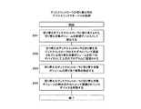
図20は、本発明の実施の形態のデバイスリンクマネージャ103がディスクコントローラ131の切り替え時に実行する処理のフローチャートである。 FIG. 20 is a flowchart of processing executed by the
図20に示す処理は、切り替えコントローラ201がディスクコントローラ切り替え処理(図14及び図15参照)を実行したときに、デバイスリンクマネージャ103が実行する処理である。 The process shown in FIG. 20 is a process executed by the
デバイスリンクマネージャ103は、最初に、切り替え先のディスクコントローラ131に割り当てられた切り替え対象の論理ボリューム135を新規デバイスとして検出する(2001)。このとき、デバイスリンクマネージャ103は、ストレージシステム130に格納された割り当て情報(図示省略)を参照してもよい。図15の例では、ディスクコントローラ2が切り替え先のディスクコントローラ131、VOL1が切り替え対象の論理ボリューム135である。The
ホスト100の上位のプログラム(例えば、アプリケーションプログラム)は、デバイスを論理的な記憶装置として認識する。デバイスは、例えば、いわゆる論理ユニット(LU)である。 A host program (for example, an application program) of the
次に、デバイスリンクマネージャ103は、切り替え元のディスクコントローラ131と切り替え対象の論理ボリューム135との組み合わせによって認識されるデバイスと、切り替え先のディスクコントローラ131と切り替え対象の論理ボリューム135との組み合わせによって認識されるデバイスとが同一であることを上位のプログラム(例えば、アプリケーションプログラム)に認識させる(2002)。図15の例では、ディスクコントローラ1が切り替え元のディスクコントローラ131である。Next, the
次に、デバイスリンクマネージャ103は、切り替え元のディスクコントローラ131と切り替え対象の論理ボリューム135との割り当ての解除を検出する(2003)。この解除は、図14のステップ1403において実行されるものである。 Next, the
次に、デバイスリンクマネージャ103は、切り替え元のディスクコントローラ131と切り替え対象の論理ボリューム135との組み合わせによって認識されるデバイスを削除する(2004)。 Next, the
以上で処理を終了する。 The process ends here.
図21は、本発明の実施の形態のデバイスリンクマネージャ103がディスクコントローラ131の追加時に実行する処理のフローチャートである。 FIG. 21 is a flowchart of processing executed by the
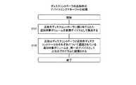
図21に示す処理は、切り替えコントローラ201がディスクコントローラ追加処理(図16及び図17参照)を実行したときに、デバイスリンクマネージャ103が実行する処理である。 The process shown in FIG. 21 is a process executed by the
なお、図21の説明において、ディスクコントローラ131の追加が実行される前に論理ボリューム135が割り当てられていたディスクコントローラ131(図17の例では、ディスクコントローラ1)を追加元のディスクコントローラと記載する。 In the description of FIG. 21, the disk controller 131 (the
デバイスリンクマネージャ103は、最初に、追加先のディスクコントローラ131に割り当てられた追加対象の論理ボリューム135を新規デバイスとして検出する(2101)。図17の例では、ディスクコントローラ2が追加先のディスクコントローラ131、VOL1が追加対象の論理ボリューム135である。 The
次に、デバイスリンクマネージャ103は、追加先のディスクコントローラ131と追加対象の論理ボリューム135との組み合わせによって認識されるデバイスと、追加元のディスクコントローラ131と追加対象の論理ボリューム135との組み合わせによって認識されるデバイスとが同一であることを上位のプログラム(例えば、アプリケーションプログラム)に認識させる(2102)。Next, the
以上で処理を終了する。 The process ends here.
図22は、本発明の実施の形態のデバイスリンクマネージャ103がペア切り替え時に実行する処理のフローチャートである。 FIG. 22 is a flowchart of processing executed by the
図22に示す処理は、切り替えコントローラ201がペア切り替え処理(図18及び図19参照)を実行したときに、デバイスリンクマネージャ103が実行する処理である。 The process shown in FIG. 22 is a process executed by the
なお、図22の説明において、切り替え対象のペアを当該ペア、切り替えられる前の当該ペアの正論理ボリュームをペア切り替え対象ボリューム、ペア切り替え対象ボリュームが割り当てられていたディスクコントローラ131をペア切り替え元ディスクコントローラ131、切り替えられる前の当該ペアの副論理ボリュームをペアボリューム、ペアボリュームが割り当てられるディスクコントローラ131をペア切り替え先ディスクコントローラ131と記載する。図19の例において、VOL1がペア切り替え対象ボリューム、ディスクコントローラ1がペア切り替え元ディスクコントローラ131、VOL2がペアボリューム、ディスクコントローラ3がペア切り替え先ディスクコントローラ131である。In the description of FIG. 22, the pair to be switched is the pair, the primary logical volume of the pair before switching is the pair switching target volume, and the
デバイスリンクマネージャ103は、最初に、ストレージマネージャ113の切り替えコントローラ201から、当該ペアに関するペア構成情報を受信する(2201)。この構成情報は、図18のステップ1804において送信されたものである。 The
次に、デバイスリンクマネージャ103は、ペア切り替え先ディスクコントローラ131に割り当てられたペアボリュームを新規デバイスとして検出する(2202)。ここで、ペア切り替え先のディスクコントローラ131とは、図18のステップ1805におけるペア切り替え可能なディスクコントローラ131である。また、ペアボリュームとは、図18のステップ1805におけるペアボリュームである。 Next, the
次に、デバイスリンクマネージャ103は、ペア切り替え対象ボリューム及びペア切り替え元ディスクコントローラ131の組み合わせによって認識されるデバイスと、ペアボリューム及びペア切り替え先ディスクコントローラ131の組み合わせによって認識されるデバイスとが同一であることを上位のプログラム(例えば、アプリケーションプログラム)に認識させる(2203)。 Next, in the
次に、デバイスリンクマネージャ103は、ペア切り替え元ディスクコントローラ131とペア切り替え対象ボリュームとの割り当ての解除を検出する(2204)。この解除は、図18のステップ1808において実行されるものである。 Next, the
次に、デバイスリンクマネージャ103は、ペア切り替え元のディスクコントローラ131とペア切り替え対象ボリュームとの組み合わせによって認識されるデバイスを削除する(2205)。 Next, the
以上で処理を終了する。 The process ends here.
以上の本発明の実施の形態において、ストレージマネージャ113は、IPネットワーク150に接続された管理サーバ110に格納され、管理サーバ110のCPU111によって実行される。しかし、ストレージマネージャ113は、FC−SW120に格納され、FC−SW120のCPU(図示省略)によって実行されてもよい。この場合において、ストレージマネージャ113がホスト100又はストレージシステム130に対して指示又はデータ等を送受信する場合、その送受信は、SANを経由して(すなわち、インバンドで)実行される。 In the above embodiment of the present invention, the
あるいは、ストレージマネージャ113は、一つのストレージシステム130に格納され、CPU132又はCPU138によって実行されてもよい。この場合も、データ等はインバンドで送受信される。 Alternatively, the
あるいは、ストレージマネージャ113は、全てのストレージシステム130に格納され、CPU132又はCPU138によって実行されてもよい。この場合、各ストレージシステム130は、そのストレージシステム130についての情報のみを管理し、その情報をSANを経由して相互に通信することによって、その情報を共有してもよい。この場合も、データ等はインバンドで送受信される。 Alternatively, the
以上の本発明の実施の形態によれば、ストレージマネージャ113は、各ディスクコントローラ131のアクセス負荷を監視し、アクセス負荷が集中している(すなわち、アクセス負荷が適切に分散されていない)と判定した場合、論理ボリューム135のディスクコントローラ131に対する割り当てを変更する。ここで、割り当ての変更とは、ディスクコントローラ131の切り替え又は追加である。あるいは、ストレージマネージャ113は、論理ボリューム135が属するペアを切り替える。その結果、ホスト100から論理ボリューム135に至る新たなパスが設定され、あるいは、設定されていたパスが削除される。ホスト100のデバイスリンクマネージャ103が、新たなパスにアクセスを割り当てることによって、ホスト100によるアクセス負荷が計算機システム全体に適切に分散される。 According to the above embodiment of the present invention, the
100 ホスト
101、111、132、138 CPU
102、112、133、139 メモリ
103 デバイスリンクマネージャ
104 アダプタ
105、114、142 ネットワークインターフェース(I/F)
110 管理サーバ
113 ストレージマネージャ
120 ファイバチャネルスイッチ(FC−SW)
121、136 ポート
130 ストレージシステム
131 ディスクコントローラ
134 キャッシュメモリ
135 論理ボリューム
137 ストレージコントローラ
140 コントローラ性能情報
141 ボリューム管理情報
150 IPネットワーク100
102, 112, 133, 139
110
121, 136
Claims (2)
Translated fromJapanese前記管理計算機は、前記複数のホスト計算機及び前記複数のストレージシステムと第1ネットワークを介して接続され、 The management computer is connected to the plurality of host computers and the plurality of storage systems via a first network,
前記複数のホスト計算機及び前記複数のストレージシステムは、第2ネットワークによって相互に接続され、 The plurality of host computers and the plurality of storage systems are connected to each other by a second network,
前記管理計算機は、前記第1ネットワークに接続される第1インターフェースと、前記第1インターフェースに接続される第1プロセッサと、前記第1プロセッサに接続される第1メモリと、を備え、 The management computer includes a first interface connected to the first network, a first processor connected to the first interface, and a first memory connected to the first processor,
前記各ホスト計算機は、前記第1ネットワークに接続される第2インターフェースと、前記第2ネットワークに接続される第3インターフェースと、前記第2インターフェース及び前記第3インターフェースに接続される第2プロセッサと、前記第2プロセッサに接続される第2メモリと、を備え、 Each of the host computers includes a second interface connected to the first network, a third interface connected to the second network, a second processor connected to the second interface and the third interface, A second memory connected to the second processor,
前記各ストレージシステムは、前記第1ネットワークに接続される第4インターフェースと、前記第4インターフェースに接続される第3プロセッサと、前記第3プロセッサに接続される第3メモリと、前記第2ネットワークに接続される一つ以上の第5インターフェースと、前記一つ以上の第5インターフェースに接続される一つ以上のコントローラと、前記ホスト計算機が使用するデータを格納する一つ以上の論理ボリュームと、を備え、 Each storage system includes a fourth interface connected to the first network, a third processor connected to the fourth interface, a third memory connected to the third processor, and a second network. One or more fifth interfaces connected; one or more controllers connected to the one or more fifth interfaces; and one or more logical volumes storing data used by the host computer; Prepared,
前記各コントローラは、前記第5インターフェースに接続される第4プロセッサと、前記第4プロセッサに接続される第4メモリと、を備え、 Each controller includes a fourth processor connected to the fifth interface, and a fourth memory connected to the fourth processor,
前記複数のストレージシステムは、少なくとも、第1論理ボリュームを備える第1ストレージシステムと、第2論理ボリュームを備える第2ストレージシステムと、を含み、 The plurality of storage systems include at least a first storage system including a first logical volume and a second storage system including a second logical volume,
前記第1論理ボリューム及び前記第2論理ボリュームは、前記第1論理ボリュームがコピー元、前記第2論理ボリュームがコピー先となるリモートコピーのペアを形成し、 The first logical volume and the second logical volume form a remote copy pair in which the first logical volume is a copy source and the second logical volume is a copy destination,
前記方法は、 The method
前記第1論理ボリュームが割り当てられている前記コントローラの性能情報が所定の閾値を超えるか否かを所定の時間が経過するごとに判定し、 Determining whether or not the performance information of the controller to which the first logical volume is allocated exceeds a predetermined threshold every time a predetermined time elapses;
前記第1論理ボリュームが割り当てられている前記コントローラの性能情報が所定の閾値を超えた場合、前記第2ストレージシステムの前記少なくとも一つのコントローラのうちの一つに前記第2論理ボリュームを割り当てたときの性能情報を予測し、 When the performance information of the controller to which the first logical volume is allocated exceeds a predetermined threshold, when the second logical volume is allocated to one of the at least one controllers of the second storage system Predict performance information,
前記予測された性能情報が前記所定の閾値を超える場合、前記一つのコントローラ以外のコントローラに前記第2論理ボリュームを割り当てたときの性能情報を予測し、 When the predicted performance information exceeds the predetermined threshold, predict performance information when the second logical volume is allocated to a controller other than the one controller,
前記予測された性能情報が前記所定の閾値を超えない場合、前記第1論理ボリューム及び前記第2論理ボリュームによって形成される前記ペアの属性が非同期モードであるか否かを判定し、 If the predicted performance information does not exceed the predetermined threshold, determine whether the attribute of the pair formed by the first logical volume and the second logical volume is an asynchronous mode;
前記ペアの属性が非同期モードである場合、前記ペアの属性を同期モードに変更し、 If the attribute of the pair is asynchronous mode, change the attribute of the pair to synchronous mode,
前記ペアが同期状態となった後に、前記第2論理ボリュームを、前記予測された性能情報が前記所定の閾値を超えないと判定されたコントローラに割り当て、 After the pair is synchronized, assign the second logical volume to a controller that has been determined that the predicted performance information does not exceed the predetermined threshold;
前記第1論理ボリュームをコピー先に変更し、 Change the first logical volume to the copy destination,
前記第2論理ボリュームをコピー元に変更し、 Change the second logical volume to the copy source,
前記第1論理ボリュームの前記コントローラへの割り当てを解除し、 Deallocating the first logical volume to the controller;
前記第2論理ボリューム及び当該第2論理ボリュームが割り当てられた前記コントローラの組み合わせによって認識されるデバイスを、前記第1論理ボリューム及び当該第1論理ボリュームが割り当てられていた前記コントローラの組み合わせによって認識されるデバイスと同一のデバイスとして前記第2プロセッサに認識させることを特徴とする方法。 A device recognized by the combination of the second logical volume and the controller to which the second logical volume is assigned is recognized by the combination of the controller to which the first logical volume and the first logical volume are assigned. A method of causing the second processor to recognize the same device as the device.
前記管理計算機は、前記複数のホスト計算機及び前記複数のストレージシステムと第1ネットワークを介して接続され、 The management computer is connected to the plurality of host computers and the plurality of storage systems via a first network,
前記複数のホスト計算機及び前記複数のストレージシステムは、第2ネットワークによって相互に接続され、 The plurality of host computers and the plurality of storage systems are connected to each other by a second network,
前記管理計算機は、前記第1ネットワークに接続される第1インターフェースと、前記第1インターフェースに接続される第1プロセッサと、前記第1プロセッサに接続される第1メモリと、を備え、 The management computer includes a first interface connected to the first network, a first processor connected to the first interface, and a first memory connected to the first processor,
前記各ホスト計算機は、前記第1ネットワークに接続される第2インターフェースと、前記第2ネットワークに接続される第3インターフェースと、前記第2インターフェース及び前記第3インターフェースに接続される第2プロセッサと、前記第2プロセッサに接続される第2メモリと、を備え、 Each of the host computers includes a second interface connected to the first network, a third interface connected to the second network, a second processor connected to the second interface and the third interface, A second memory connected to the second processor,
前記各ストレージシステムは、前記第1ネットワークに接続される第4インターフェースと、前記第4インターフェースに接続される第3プロセッサと、前記第3プロセッサに接続される第3メモリと、前記第2ネットワークに接続される一つ以上の第5インターフェースと、前記一つ以上の第5インターフェースに接続される一つ以上のコントローラと、前記ホスト計算機が使用するデータを格納する一つ以上の論理ボリュームと、を備え、 Each storage system includes a fourth interface connected to the first network, a third processor connected to the fourth interface, a third memory connected to the third processor, and a second network. One or more fifth interfaces connected; one or more controllers connected to the one or more fifth interfaces; and one or more logical volumes storing data used by the host computer; Prepared,
前記各コントローラは、前記第5インターフェースに接続される第4プロセッサと、前記第4プロセッサに接続される第4メモリと、を備え、 Each controller includes a fourth processor connected to the fifth interface, and a fourth memory connected to the fourth processor,
前記複数のストレージシステムは、少なくとも、第1論理ボリュームを備える第1ストレージシステムと、第2論理ボリュームを備える第2ストレージシステムと、を含み、 The plurality of storage systems include at least a first storage system including a first logical volume and a second storage system including a second logical volume,
前記第1論理ボリューム及び前記第2論理ボリュームは、前記第1論理ボリュームがコピー元、前記第2論理ボリュームがコピー先となるリモートコピーのペアを形成し、 The first logical volume and the second logical volume form a remote copy pair in which the first logical volume is a copy source and the second logical volume is a copy destination,
前記第1プロセッサは、 The first processor is
前記第1論理ボリュームが割り当てられている前記コントローラの性能情報が所定の閾値を超えるか否かを所定の時間が経過するごとに判定し、 Determining whether or not the performance information of the controller to which the first logical volume is allocated exceeds a predetermined threshold every time a predetermined time elapses;
前記第1論理ボリュームが割り当てられている前記コントローラの性能情報が所定の閾値を超えた場合、前記第2ストレージシステムの前記少なくとも一つのコントローラのうちの一つに前記第2論理ボリュームを割り当てたときの性能情報を予測し、 When the performance information of the controller to which the first logical volume is allocated exceeds a predetermined threshold, when the second logical volume is allocated to one of the at least one controllers of the second storage system Predict performance information,
前記予測された性能情報が前記所定の閾値を超える場合、前記一つのコントローラ以外のコントローラに前記第2論理ボリュームを割り当てたときの性能情報を予測し、 When the predicted performance information exceeds the predetermined threshold, predict performance information when the second logical volume is allocated to a controller other than the one controller,
前記予測された性能情報が前記所定の閾値を超えない場合、前記第1論理ボリューム及び前記第2論理ボリュームによって形成される前記ペアの属性が非同期モードであるか否かを判定し、 If the predicted performance information does not exceed the predetermined threshold, determine whether the attribute of the pair formed by the first logical volume and the second logical volume is an asynchronous mode;
前記ペアの属性が非同期モードである場合、前記ペアの属性を同期モードに変更し、 If the attribute of the pair is asynchronous mode, change the attribute of the pair to synchronous mode,
前記ペアが同期状態となった後に、前記第2論理ボリュームを、前記予測された性能情報が前記所定の閾値を超えないと判定されたコントローラに割り当て、 After the pair is synchronized, assign the second logical volume to a controller that has been determined that the predicted performance information does not exceed the predetermined threshold;
前記第1論理ボリュームをコピー先に変更し、 Change the first logical volume to the copy destination,
前記第2論理ボリュームをコピー元に変更し、 Change the second logical volume to the copy source,
前記第1論理ボリュームの前記コントローラへの割り当てを解除し、 Deallocating the first logical volume to the controller;
前記第1論理ボリューム及び前記第2論理ボリュームがペアを構成することを示すペア構成情報を、前記第1論理ボリュームを使用する前記ホスト計算機に送信し、 Sending pair configuration information indicating that the first logical volume and the second logical volume constitute a pair to the host computer using the first logical volume;
前記第2プロセッサは、前記ペア構成情報を受信し、前記第2論理ボリューム及び当該第2論理ボリュームが割り当てられた前記コントローラの組み合わせによって認識されるデバイスを、前記第1論理ボリューム及び当該第1論理ボリュームが割り当てられていた前記コントローラの組み合わせによって認識されるデバイスと同一のデバイスとして認識することを特徴とする計算機システム。 The second processor receives the pair configuration information, and recognizes a device recognized by a combination of the second logical volume and the controller to which the second logical volume is assigned as the first logical volume and the first logical volume. A computer system that recognizes a device that is the same as a device recognized by a combination of the controllers to which a volume is assigned.
Priority Applications (2)
| Application Number | Priority Date | Filing Date | Title |
|---|---|---|---|
| JP2005305749AJP4790372B2 (en) | 2005-10-20 | 2005-10-20 | Computer system for distributing storage access load and control method thereof |
| US11/296,313US8683482B2 (en) | 2005-10-20 | 2005-12-08 | Computer system for balancing access load of storage systems and control method therefor |
Applications Claiming Priority (1)
| Application Number | Priority Date | Filing Date | Title |
|---|---|---|---|
| JP2005305749AJP4790372B2 (en) | 2005-10-20 | 2005-10-20 | Computer system for distributing storage access load and control method thereof |
Publications (2)
| Publication Number | Publication Date |
|---|---|
| JP2007115019A JP2007115019A (en) | 2007-05-10 |
| JP4790372B2true JP4790372B2 (en) | 2011-10-12 |
Family
ID=37986556
Family Applications (1)
| Application Number | Title | Priority Date | Filing Date |
|---|---|---|---|
| JP2005305749AExpired - Fee RelatedJP4790372B2 (en) | 2005-10-20 | 2005-10-20 | Computer system for distributing storage access load and control method thereof |
Country Status (2)
| Country | Link |
|---|---|
| US (1) | US8683482B2 (en) |
| JP (1) | JP4790372B2 (en) |
Families Citing this family (21)
| Publication number | Priority date | Publication date | Assignee | Title |
|---|---|---|---|---|
| JP4842593B2 (en) | 2005-09-05 | 2011-12-21 | 株式会社日立製作所 | Device control takeover method for storage virtualization apparatus |
| US7710040B2 (en)* | 2006-05-05 | 2010-05-04 | Virgin Islands Microsystems, Inc. | Single layer construction for ultra small devices |
| JP4331742B2 (en)* | 2006-10-25 | 2009-09-16 | 株式会社日立製作所 | Computer system, computer and method for managing performance based on I/O allocation ratio |
| JP2008287405A (en)* | 2007-05-16 | 2008-11-27 | Hitachi Ltd | Path management method, host computer and path management program |
| JP4958641B2 (en)* | 2007-05-29 | 2012-06-20 | 株式会社日立製作所 | Storage control device and control method thereof |
| JP2009009194A (en) | 2007-06-26 | 2009-01-15 | Hitachi Ltd | Storage system with a function to reduce power consumption |
| JP4475598B2 (en)* | 2007-06-26 | 2010-06-09 | 株式会社日立製作所 | Storage system and storage system control method |
| JP5352132B2 (en)* | 2008-06-19 | 2013-11-27 | 株式会社日立製作所 | Computer system and method for changing I/O configuration thereof |
| JP5193801B2 (en)* | 2008-10-29 | 2013-05-08 | 株式会社日立製作所 | Storage system performance improvement or management method, system, apparatus and program |
| US8589625B2 (en)* | 2010-09-15 | 2013-11-19 | Pure Storage, Inc. | Scheduling of reconstructive I/O read operations in a storage environment |
| JP5636853B2 (en) | 2010-10-04 | 2014-12-10 | 富士通株式会社 | Storage system virtualization control apparatus and control program |
| JP5193327B2 (en)* | 2011-02-28 | 2013-05-08 | シャープ株式会社 | Image forming apparatus |
| US8554951B2 (en) | 2011-03-08 | 2013-10-08 | Rackspace Us, Inc. | Synchronization and ordering of multiple accessess in a distributed system |
| US8712975B2 (en) | 2011-03-08 | 2014-04-29 | Rackspace Us, Inc. | Modification of an object replica |
| US8538926B2 (en)* | 2011-03-08 | 2013-09-17 | Rackspace Us, Inc. | Massively scalable object storage system for storing object replicas |
| US8510267B2 (en) | 2011-03-08 | 2013-08-13 | Rackspace Us, Inc. | Synchronization of structured information repositories |
| JP5874933B2 (en)* | 2013-01-29 | 2016-03-02 | 日本電気株式会社 | Path control device, path control method, and path control program |
| US20150293708A1 (en)* | 2014-04-11 | 2015-10-15 | Netapp, Inc. | Connectivity-Aware Storage Controller Load Balancing |
| US10002025B2 (en)* | 2014-08-29 | 2018-06-19 | Hitachi, Ltd. | Computer system and load leveling program |
| WO2017094077A1 (en)* | 2015-11-30 | 2017-06-08 | 株式会社日立製作所 | Storage system and method for controlling storage system |
| CN115495288B (en)* | 2022-11-17 | 2023-03-10 | 苏州浪潮智能科技有限公司 | A data backup method, device, equipment and computer-readable storage medium |
Family Cites Families (14)
| Publication number | Priority date | Publication date | Assignee | Title |
|---|---|---|---|---|
| JPH07121307A (en)* | 1993-10-21 | 1995-05-12 | Fuji Xerox Co Ltd | Multiplexed disk device |
| US6173306B1 (en)* | 1995-07-21 | 2001-01-09 | Emc Corporation | Dynamic load balancing |
| US6341333B1 (en)* | 1997-10-06 | 2002-01-22 | Emc Corporation | Method for transparent exchange of logical volumes in a disk array storage device |
| JP3726484B2 (en)* | 1998-04-10 | 2005-12-14 | 株式会社日立製作所 | Storage subsystem |
| JP3534302B2 (en) | 1999-05-19 | 2004-06-07 | 日本電気株式会社 | Multipath system for storage devices |
| US6684306B1 (en)* | 1999-12-16 | 2004-01-27 | Hitachi, Ltd. | Data backup in presence of pending hazard |
| JP4220724B2 (en)* | 2002-05-21 | 2009-02-04 | 株式会社日立製作所 | Storage device |
| JP4325843B2 (en)* | 2002-12-20 | 2009-09-02 | 株式会社日立製作所 | Logical volume copy destination performance adjustment method and apparatus |
| JP2004220450A (en)* | 2003-01-16 | 2004-08-05 | Hitachi Ltd | Storage device, its introduction method, and its introduction program |
| JP2005018510A (en)* | 2003-06-27 | 2005-01-20 | Hitachi Ltd | Data center system and control method thereof |
| JP2005141381A (en)* | 2003-11-05 | 2005-06-02 | Hitachi Ltd | Storage system |
| JP2005157867A (en)* | 2003-11-27 | 2005-06-16 | Hitachi Ltd | Storage system, storage controller, and data relay method using storage controller |
| JP2005165444A (en)* | 2003-11-28 | 2005-06-23 | Hitachi Ltd | Disk array device and method for controlling disk array device |
| US7305520B2 (en)* | 2004-01-30 | 2007-12-04 | Hewlett-Packard Development Company, L.P. | Storage system with capability to allocate virtual storage segments among a plurality of controllers |
- 2005
- 2005-10-20JPJP2005305749Apatent/JP4790372B2/ennot_activeExpired - Fee Related
- 2005-12-08USUS11/296,313patent/US8683482B2/ennot_activeExpired - Fee Related
Also Published As
| Publication number | Publication date |
|---|---|
| US20070094357A1 (en) | 2007-04-26 |
| JP2007115019A (en) | 2007-05-10 |
| US8683482B2 (en) | 2014-03-25 |
Similar Documents
| Publication | Publication Date | Title |
|---|---|---|
| JP4790372B2 (en) | Computer system for distributing storage access load and control method thereof | |
| JP4842593B2 (en) | Device control takeover method for storage virtualization apparatus | |
| US7171522B2 (en) | Storage system including storage adaptors having cache memories and grasping usage situation of each cache memory and equalizing usage of cache memories | |
| US8078690B2 (en) | Storage system comprising function for migrating virtual communication port added to physical communication port | |
| US9329795B2 (en) | Logical volume transfer method and storage network system | |
| US7711896B2 (en) | Storage system that is connected to external storage | |
| US6950914B2 (en) | Storage system | |
| US20040103254A1 (en) | Storage apparatus system and data reproduction method | |
| US20050144173A1 (en) | Method for coupling storage devices of cluster storage | |
| JP4896500B2 (en) | Virtual volume control method with device stop | |
| JP2007072571A (en) | Computer system, management computer, and access path management method | |
| US7886186B2 (en) | Storage system and management method for the same | |
| JP2005092308A (en) | Disk management method and computer system | |
| EP1486862A2 (en) | Storage system and data reproduction method |
Legal Events
| Date | Code | Title | Description |
|---|---|---|---|
| A621 | Written request for application examination | Free format text:JAPANESE INTERMEDIATE CODE: A621 Effective date:20080707 | |
| A977 | Report on retrieval | Free format text:JAPANESE INTERMEDIATE CODE: A971007 Effective date:20110215 | |
| A131 | Notification of reasons for refusal | Free format text:JAPANESE INTERMEDIATE CODE: A131 Effective date:20110222 | |
| A521 | Request for written amendment filed | Free format text:JAPANESE INTERMEDIATE CODE: A523 Effective date:20110419 | |
| TRDD | Decision of grant or rejection written | ||
| A01 | Written decision to grant a patent or to grant a registration (utility model) | Free format text:JAPANESE INTERMEDIATE CODE: A01 Effective date:20110621 | |
| A01 | Written decision to grant a patent or to grant a registration (utility model) | Free format text:JAPANESE INTERMEDIATE CODE: A01 | |
| A61 | First payment of annual fees (during grant procedure) | Free format text:JAPANESE INTERMEDIATE CODE: A61 Effective date:20110720 | |
| FPAY | Renewal fee payment (event date is renewal date of database) | Free format text:PAYMENT UNTIL: 20140729 Year of fee payment:3 | |
| R150 | Certificate of patent or registration of utility model | Free format text:JAPANESE INTERMEDIATE CODE: R150 | |
| LAPS | Cancellation because of no payment of annual fees |