JP4788409B2 - Cross current blower and electronic device - Google Patents
Cross current blower and electronic deviceDownload PDFInfo
- Publication number
- JP4788409B2 JP4788409B2JP2006064134AJP2006064134AJP4788409B2JP 4788409 B2JP4788409 B2JP 4788409B2JP 2006064134 AJP2006064134 AJP 2006064134AJP 2006064134 AJP2006064134 AJP 2006064134AJP 4788409 B2JP4788409 B2JP 4788409B2
- Authority
- JP
- Japan
- Prior art keywords
- impeller
- cross
- blades
- connecting plate
- predetermined direction
- Prior art date
- Legal status (The legal status is an assumption and is not a legal conclusion. Google has not performed a legal analysis and makes no representation as to the accuracy of the status listed.)
- Expired - Fee Related
Links
Images


Classifications
- F—MECHANICAL ENGINEERING; LIGHTING; HEATING; WEAPONS; BLASTING
- F04—POSITIVE - DISPLACEMENT MACHINES FOR LIQUIDS; PUMPS FOR LIQUIDS OR ELASTIC FLUIDS
- F04D—NON-POSITIVE-DISPLACEMENT PUMPS
- F04D29/00—Details, component parts, or accessories
- F04D29/26—Rotors specially for elastic fluids
- F04D29/28—Rotors specially for elastic fluids for centrifugal or helico-centrifugal pumps for radial-flow or helico-centrifugal pumps
- F04D29/281—Rotors specially for elastic fluids for centrifugal or helico-centrifugal pumps for radial-flow or helico-centrifugal pumps for fans or blowers
- F04D29/282—Rotors specially for elastic fluids for centrifugal or helico-centrifugal pumps for radial-flow or helico-centrifugal pumps for fans or blowers the leading edge of each vane being substantially parallel to the rotation axis
- F04D29/283—Rotors specially for elastic fluids for centrifugal or helico-centrifugal pumps for radial-flow or helico-centrifugal pumps for fans or blowers the leading edge of each vane being substantially parallel to the rotation axis rotors of the squirrel-cage type
- F—MECHANICAL ENGINEERING; LIGHTING; HEATING; WEAPONS; BLASTING
- F04—POSITIVE - DISPLACEMENT MACHINES FOR LIQUIDS; PUMPS FOR LIQUIDS OR ELASTIC FLUIDS
- F04D—NON-POSITIVE-DISPLACEMENT PUMPS
- F04D17/00—Radial-flow pumps, e.g. centrifugal pumps; Helico-centrifugal pumps
- F04D17/02—Radial-flow pumps, e.g. centrifugal pumps; Helico-centrifugal pumps having non-centrifugal stages, e.g. centripetal
- F04D17/04—Radial-flow pumps, e.g. centrifugal pumps; Helico-centrifugal pumps having non-centrifugal stages, e.g. centripetal of transverse-flow type
- F—MECHANICAL ENGINEERING; LIGHTING; HEATING; WEAPONS; BLASTING
- F04—POSITIVE - DISPLACEMENT MACHINES FOR LIQUIDS; PUMPS FOR LIQUIDS OR ELASTIC FLUIDS
- F04D—NON-POSITIVE-DISPLACEMENT PUMPS
- F04D25/00—Pumping installations or systems
- F04D25/02—Units comprising pumps and their driving means
- F04D25/06—Units comprising pumps and their driving means the pump being electrically driven
- F04D25/0606—Units comprising pumps and their driving means the pump being electrically driven the electric motor being specially adapted for integration in the pump
- F—MECHANICAL ENGINEERING; LIGHTING; HEATING; WEAPONS; BLASTING
- F04—POSITIVE - DISPLACEMENT MACHINES FOR LIQUIDS; PUMPS FOR LIQUIDS OR ELASTIC FLUIDS
- F04D—NON-POSITIVE-DISPLACEMENT PUMPS
- F04D29/00—Details, component parts, or accessories
- F04D29/60—Mounting; Assembling; Disassembling
- F04D29/62—Mounting; Assembling; Disassembling of radial or helico-centrifugal pumps
- F04D29/624—Mounting; Assembling; Disassembling of radial or helico-centrifugal pumps especially adapted for elastic fluid pumps
- F04D29/626—Mounting or removal of fans
Landscapes
- Engineering & Computer Science (AREA)
- Mechanical Engineering (AREA)
- General Engineering & Computer Science (AREA)
- Structures Of Non-Positive Displacement Pumps (AREA)
Description
Translated fromJapanese本発明は、回転軸にほぼ直交する方向に送風する横流送風装置、これを搭載した電子機器、横流送風装置に搭載される羽根車に関する。The present invention relates to a crossflow fan that blows air in a direction substantiallyorthogonal to a rotation axis, an electronic device equipped with the blower, and an impeller mounted on the crossflow fan.
従来から、モータの回転軸にほぼ直交する方向に送風する、いわゆる横流送風機(クロスフローファン)は、主に空気調和機に用いられている。横流送風機は、モータの回転軸にほぼ平行な面状の気流を発生するので、エアカーテンにも用いられる場合がある。
Conventionally, so-called cross-flow fans (cross-flow fans) that blow air in a direction substantiallyorthogonal to the rotating shaft of a motor are mainly used in air conditioners. Since the crossflow blower generates a planar airflow substantially parallel to the rotation axis of the motor, it may be used for an air curtain.
かかる横流送風機は、ファン本体(羽根車)の一端にモータの回転軸が取り付けられ、ファン本体の、回転軸とは反対側には当該モータの回転軸と同軸の回転軸が、軸受に回転自在に支持されて構成されている(例えば、特許文献1、2参照。)。このような一般的な横流送風機では、金属による板金の組立であるため、ファン本体の回転のアンバランスが発生しやすい。したがって、特許文献1、2に記載のように、ファン本体の両側で軸受により当該ファン本体が支持され、回転の安定化が図れている。
しかしながら、ファン本体の両側に軸受が設けられる場合、その回転軸の芯出しが精度良く行われなければならず、横流送風機の製造が容易ではない。また、両側に軸受が設けられるので、その分コストが増大するという問題がある。 However, when bearings are provided on both sides of the fan body, the rotating shaft must be centered with high accuracy, and the manufacture of the cross-flow blower is not easy. In addition, since bearings are provided on both sides, there is a problem that the cost increases accordingly.
以上のような事情に鑑み、本発明の目的は、製造を容易にし、製造コストを低減することができる横流送風装置及び電子機器等を提供することにある。 In view of the circumstances as described above, it is an object of the present invention to provide a cross-flow blower, an electronic device, and the like that can facilitate manufacture and reduce manufacturing costs.
上記目的を達成するため、本発明に係る横流送風装置は、
所定の方向に延び環状に並ぶように配置された複数のブレードと、前記所定の方向における第1の側で前記各ブレードを連結する環状の第1の連結板と、前記第1の側とは前記所定の方向で反対側の第2の側で前記各ブレードを連結する第2の連結板とを有し、前記ブレードが、前記回転軸の方向に平行であって、平面でなる第1の主面と、前記第1の主面とは反対側に設けられ、前記第1の主面に対して角度を有し、前記回転軸の方向に平行であって平面でなる第2の主面とを有し、一体成型の樹脂でなる羽根車と、
前記第2の連結板に装着され前記所定方向に沿って設けられた回転軸を有し、前記羽根車を回転駆動するモータと、
前記回転軸で前記羽根車を片持ちさせるように、前記モータを支持する支持体と、
前記羽根車の外側から前記第1の連結板の内側を介して前記各ブレードに囲まれる領域に突出するように前記支持体に設けられた突出部材と
を具備する。
また、本発明に係る電子機器は、
発熱体と、
前記発熱体及び上記横流送風装置を内蔵する筐体とを具備する。In order to achieve the above object, a cross-flow blower according to the present invention includes:
A plurality of blades arranged in an annular shape extending in a predetermined direction, an annular first connecting plate for connecting the blades on a first side in the predetermined direction, and the first side; A second connecting plate for connecting the blades on the second side opposite to the predetermined direction, wherein the blades are parallel to the direction of the rotation axis and are planar. A main surface and a second main surface that is provided on the opposite side of the first main surface, has an angle with respect to the first main surface, is parallel to the direction of the rotation axis, and is a plane. And an impeller made of integrally molded resin,
A motor mounted on the second connecting plate and provided along the predetermined direction, the motor driving the impeller,
A support that supports the motor so that the impeller is cantilevered by the rotating shaft;
A projecting member provided on the support so as to project from an outside of the impeller to an area surrounded by the blades through an inner side of the first connecting plate;
It comprises.
In addition, the electronic device according to the present invention is
A heating element;
The heating element and a housing incorporating the cross-flow fan are included.
以上のように、本発明によれば、横流送風装置の製造を容易にし、製造コストを低減することができる。 As described above, according to the present invention, it is possible to facilitate the manufacture of the crossflow fan and reduce the manufacturing cost.
以下、本発明の実施の形態を図面に基づき説明する。 Hereinafter, embodiments of the present invention will be described with reference to the drawings.
図1は、参考例に係る、横流送風装置に搭載される羽根車を示す斜視図である。図2は、図1に示す羽根車を搭載した横流送風装置を示す断面図である。FIG. 1 is a perspective view showing an impeller mounted on a cross-flow blower according to areference example . FIG. 2 is a cross-sectional view showing a cross-flow blower equipped with the impeller shown in FIG.
羽根車5は、所定の方向に延びる複数のブレード1を有する。各ブレード1は、ほぼ等間隔で環状に並んで配置されるように、例えば円板状の連結部材2及び3により連結されている。連結部材2の中央にはボス部2aが設けられ、ボス部2aにモータ6の回転軸7が装着されている。各ブレード1は、その回転軸7の軸方向(Y方向)に沿って延びるように設けられている。 The
モータ6は、その回転軸7を回転可能に支持する軸受9と、軸受9の周囲に配置されたコイル8とを有するステータ11を備えている。また、モータ6は、当該回転軸7に装着されるとともにマグネット4が固定されたロータ12を備えている。 The motor 6 includes a
軸受9は、例えば流体軸受、あるいは流体動圧軸受が用いられる。すなわち、軸受9は、ハウジング14内に、内周部に図示しない動圧溝を有するスリーブ部材15が収容されて構成されている。スリーブ部材15と回転軸7との間には、油等の流体が充填されている。あるいは、スリーブ部材15は焼結金属でなり、油が含浸されたものであってもよい。このような流体動圧軸受が用いられることにより、回転軸7と軸受9の剛性が高まり、回転軸7のぶれを抑えることができ、安定した回転を実現できる。なお、必ずしも流体軸受に限られず、ボール軸受であってもよい。 For example, a fluid bearing or a fluid dynamic pressure bearing is used as the
モータ6は、その回転軸7で羽根車5を片持ちさせるように、支持体16により支持されている。具体的には、モータ6が例えばネジ13等によって支持体16に固定されている。 The motor 6 is supported by a
このように構成された横流送風装置10では、モータ6の駆動により羽根車5が回転すると、個々のブレード1の周囲でそれぞれ圧力差が発生し、空気が羽根車5の外部から内部(個々のブレード1で囲まれる領域)に向かい、再び外部に抜けることで送風される。例えば、羽根車5の外部から内部に入った気流が再び外部へ出力されるように、各ブレード1の主面の角度や形状等が設計されている。 In the
以上のように、上記横流送風装置10は、モータ6の回転軸7が羽根車5を片持ちで支持する構成であるので、羽根車の両側に設けられた軸受によって羽根車が支持される従来の方式に比べ、部品点数が削減される結果、製造が容易になり製造コストも低減される。Asdescribed above, the
特に、羽根車5が樹脂で構成されると非常に有利になる。その場合、羽根車5が軽量化されるため、アンバランス量も少なく、片持ちであっても羽根車5の回転が安定する。また、この参考例では、羽根車5が小型の場合にも有効である。In particular, it is very advantageous if the
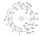
羽根車5が樹脂で形成される場合、一体成型により作製することも可能である。羽根車5が一体成型により作製される場合、図3及び図4に示すような羽根車が作製される。図3は、一体成型により作製された羽根車を示す断面図であり、図4は、図3におけるA−A線断面図である。図4中、矢印Rが回転の方向である。 When the
この羽根車25は、各ブレード25cの第1の主面25d、及びその反対側の第2の主面25eがそれぞれ平面でなる。このように平面に形成されることにより、例えば型による成型の後、型抜きをする場合に、ブレード25cの数の分だけ分割した型を図4に示すように矢印aの方向に直線的に引き出すことができるからである。従来のようにブレード25cの主面が湾曲する場合、そのような型抜きは難しい。また、もちろん各ブレード25cを連結する連結板25a及び25bは、各ブレード25cと一体成型することができる。連結板25aの中央には、モータ6の回転軸7が挿通されるボス部25fが形成されている。 In the impeller 25, the first
図4に示すように、第1の主面25dに対し第2の主面25eは角度を有している。第1の主面25dと第2の主面25eとがつながる外周面25g及び内周面25hは例えば円弧状(曲面状)に形成されているが、平面に形成されていてもよい。第1の主面25dと第2の主面25eとがなす角度αの設定が、α>0°とすると、必然的に隣接するブレード25cの放射方向に構成されるブレード25cの開口角度βが、β<(360°/n)となる。nはブレード25cの枚数である。参考として、n=12、α=15°と設定された場合、β=15°となる。これを、n=12、α=0°、β=30°、つまり第1及び第2の主面が平行でなるブレードを有する羽根車と比較した場合、発生風量が約20%向上したことが実験で確認されている。 As shown in FIG. 4, the second
従来では、ブレード25cの1本1本が両側の連結板に装着されることで羽根車が作製されていたが、羽根車25全体が一体成型されることにより、飛躍的に製造工程が簡易化される。さらに、一体成型されることにより、羽根車25の寸法精度、形状精度等が向上するため、後の手加工が要らず、羽根車25の回転のアンバランスも低減され、安定した回転が可能になる。回転が安定する結果、上記で説明した、片持ち構造の利点が特に生かされる。すなわち、片持ち構造であっても安定して回転させることが可能となる。 Conventionally, an impeller is manufactured by attaching each of the
なお、羽根車25が一体成型されることにより、径(図4に示す連結板25a及び25bの直径)が25mm以下であっても、容易に作製することが可能となる。 In addition, when the impeller 25 is integrally molded, even if the diameter (the diameter of the connecting
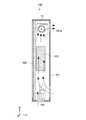
図5は、本発明の他の実施の形態に係る横流送風装置を示す断面図である。これ以降の説明では、図2等に示した実施の形態に係る横流送風装置10の部材や機能等について同様のものは説明を簡略または省略し、異なる点を中心に説明する。 FIG. 5 is a cross-sectional view showing a cross-flow blower according to another embodiment of the present invention. In the following description, the description of the members and functions of the
本実施の形態に係る横流送風装置20は、羽根車35の、モータ6が配置される側(連結板25aが設けられる側)とは反対側(連結板35bが設けられる側)に、羽根車35を非接触で支持する支持機構21を備えている。具体的には、支持機構21は、モータ6の回転軸7に同軸で羽根車35に装着されたピボット軸22と、ピボット軸22の近傍に配置され支持体26に固定されたマグネット23とを有している。ピボット軸22は、連結板35bのボス部35dに装着されている。マグネット23の形状は、図5に示した形態に限られず、例えばピボット軸22を囲む環状であってもよいし、その環状の一部である円弧ブロック状であってもよい。なお、符号35cがブレードである。 The
ピボット軸22が磁性体、例えば鉄やニッケル等でなっていれば、ピボット軸22には、マグネット23からの磁気吸引力が働く。これにより、常にピボット軸22の径方向(Y−Z平面内での方向)に非接触状態で負荷が与えられ、アンバランスによる振動やホワール現象が抑制される。 If the pivot shaft 22 is made of a magnetic material such as iron or nickel, a magnetic attraction force from the
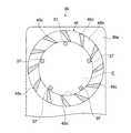
図6は、本発明のさらに別の実施の形態に係る横流送風装置の一部を示す断面図である。図7は、図6におけるB−B線断面図である。この横流送風装置30の支持体には、突出部材37が設けられた側板36aが設けられている。側板36aは、図6に示すように支持体36の一部であってもよいし、支持体36に固定された部材であってもよい。突出部材37は例えば、板金から切り起こされて形成されたものであってもよいし、成型により形成されたものであってもよい。羽根車45の、モータ6が配置される側の連結板45aとは反対側の連結板45bには穴45dが形成されている。突出部材37は、羽根車45の外部からその連結板45bの穴45dを介して各ブレード45cに囲まれた領域E(図7参照)に突出している。FIG. 6 is a cross-sectional view showing a part of a cross-flow blower according to still another embodiment of the present invention. 7 is a cross-sectional view taken along line BB in FIG. A
図6及び図7では、突出部材37は複数設けられているが、1つであってもよい。突出部材37が複数の場合、突出部材37は図7に示すように環状に等間隔に設けられてもよいが、等間隔でなくてもよい。 6 and 7, a plurality of protruding
このように本実施の形態に係る横流送風装置30によれば、横流送風装置30の姿勢が変わり、仮に回転軸7がぶれたとしても、突出部材37が連結板45bの内周部(穴)45dに接触してストッパーの機能を果たすので、羽根車45全体が大きなぶれを発生することはない。 As described above, according to the
図8は、本発明のさらに別の実施の形態に係る横流送風装置の一部を示す断面図である。この横流送風装置40の支持体46には、上記ピボット軸42を軸方向に、力Fで押圧する押圧部材41が取り付けられている。押圧部材41は、ピボット軸42の先端42aが接触するピボット座面41aを有する。この押圧部材41は、金属、樹脂、またはゴム等でなる。 FIG. 8 is a cross-sectional view showing a part of a cross-flow blower according to still another embodiment of the present invention. A pressing
従来のように、羽根車の両側に軸受が設けられる構成に比べ、本実施の形態に係る横流送風装置40は、上記のようにピボット軸42の先端42aが接触するピボット座面41aが設けられるだけの単純な構造となっている。これにより、羽根車35が安定して回転することはもちろん、製造が容易になり、製造コストが低減される。 Compared to the conventional configuration in which bearings are provided on both sides of the impeller, the
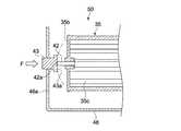
押圧部材の変形例として、図9に示す横流送風装置50のように、曲面でなるピボット座面43aを有する押圧部材43も考えられる。この場合、曲面は、球面、楕円面、双曲面、または放物面等が考えられ、あるいはこれらの組み合わせも考えられる。 As a modification of the pressing member, a pressing
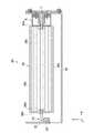
図10は、本発明のさらに別の実施の形態に係る羽根車を示す断面図である。この羽根車55には、係合突起55d及び係合溝55eが設けられた羽根車である。図11に示すように、例えば係合突起55dは、環状の連結板55bに120°間隔で3つ形成されている。係合溝55eは、この係合突起55dが嵌合するような大きさに形成され、例えば連結板55bに120°間隔で3つ形成されている。隣り合う係合突起55dと係合溝55eの角度間隔は、例えば60°に設定されている。また、連結板55bとは反対側の連結板55aにも同様な係合突起55d及び係合溝55eが形成されている。これにより、図11に示すように、羽根車55を回転軸の方向で多段に連結することができ、所望の長さの羽根車(あるいはブレード)を実現することができる。 FIG. 10 is a cross-sectional view showing an impeller according to still another embodiment of the present invention. The
なお、連結板55bに形成される係合突起55d及び係合溝55eの配置は、その連結板55bの反対側の連結板55aに形成される係合突起55d及び係合溝55eの配置に比べ、60°の角度だけずれている。これにより、複数の羽根車55の連結が可能となる。 The arrangement of the engaging
図12は、上記した各横流送風装置10、20等のうちいずれかの横流送風装置が搭載された電子機器を示す模式的な断面図である。図12では、電子機器100として例えば液晶ディスプレイ等のFPD(Flat Panel Display)装置を示す。FPD装置100は、筐体101内に、ファン104、横流送風装置10及び発熱体として回路基板等を有するディスプレイパネル102、電源等のその他の部品103が収容されている。ディスプレイパネル102から発生する熱が筐体101にこもる。ファン104により筐体101内に外気が吸入され、横流送風装置10が動作することにより、熱を含む空気を、例えば筐体101に形成された排気口101aを介して外部へ排出することができる。 FIG. 12 is a schematic cross-sectional view showing an electronic device in which any one of the above-described
なお、横流送風装置10のX方向の長さは、例えば図12ではディスプレイ100の筐体101の横方向であるX方向の長さに応じて適宜設計が可能である。「ディスプレイ」の概念には、液晶ディスプレイのほかに、プラズマディスプレイ、プラズマアドレス液晶ディスプレイ、LED(Light Emitting Diode)ディスプレイ、電界放出型ディスプレイ(FED(Field Emission Display)、SED(Surface-conduction Electron-emitter Display))、EL(Electro-Luminescence)ディスプレイ(有機及び無機両方を含む。)等を含む。 Note that the length in the X direction of the
本発明は以上説明した実施の形態には限定されるものではなく、種々の変形が可能である。 The present invention is not limited to the embodiment described above, and various modifications are possible.
例えば、図5に示した非接触の支持機構21が設けられる形態と、図6及び図7に示した突出部材37が設けられる形態とを組み合わせた形態も考えられる。あるいは、図6及び図7に示した突出部材37が設けられる形態と、図8または図9で示した押圧部材41等が設けられる形態とを組み合わせた形態も考えられる。 For example, the form which combined the form in which the
上記各実施の形態で示した羽根車5等は、特に説明のない限り、一体成型でない羽根車であってもよいし、一体成型の羽根車であってもよい。 Unless otherwise specified, the
図12に示す電子機器として、ディスプレイに限られない。例えば、空気調和機、コンピュータ(例えばPC(Personal Computer)等)、プロジェクタ、オーディオ/ビジュアル機器、ゲーム機器、カーナビゲーション機器、ロボット機器、エアカーテン機器、その他の電化製品等が挙げられる。 The electronic device illustrated in FIG. 12 is not limited to a display. For example, an air conditioner, a computer (for example, PC (Personal Computer), etc.), a projector, an audio / visual device, a game device, a car navigation device, a robot device, an air curtain device, and other electrical appliances may be used.
1、25c、35c、45c、55c…ブレード
2…連結部材
2a…ボス部
5、25、35、45、55…羽根車
6…モータ
7…回転軸
9…軸受
10、20、30、40、50…横流送風装置
21…支持機構
22、42…ピボット軸
23…マグネット
25d…第1の主面
25e…第2の主面
25a…連結板
26…支持体
37…突出部材
41…押圧部材
41a、43a…ピボット座面
42a…先端
55d…係合突起
55e…係合溝
100…FPD装置(電子機器)
101…筐体DESCRIPTION OF
101 ... Case
Claims (9)
Translated fromJapanese前記第2の連結板に装着され前記所定方向に沿って設けられた回転軸を有し、前記羽根車を回転駆動するモータと、
前記回転軸で前記羽根車を片持ちさせるように、前記モータを支持する支持体と、
前記羽根車の外側から前記第1の連結板の内側を介して前記各ブレードに囲まれる領域に突出するように前記支持体に設けられた突出部材と
を具備する横流送風装置。A plurality of bladesarranged in an annular shape extending in a predetermined direction,an annular first connecting plate for connecting the blades on a first side in the predetermined direction, and the first side; A second connecting plate for connecting the blades on the second side opposite to the predetermined direction, wherein the blades are parallel to the direction of the rotation axis and are planar. A main surface and a second main surface that is provided on the opposite side of the first main surface, has an angle with respect to the first main surface, is parallel to the direction of the rotation axis, and is a plane. And an impeller made ofintegrally molded resin ,
A motormounted on the second connecting plate and provided along the predetermined direction, the motor driving the impeller,
A support that supports the motor so that the impeller is cantilevered by the rotating shaft;
A cross-flow blower comprising:a projecting member provided on the support so as to project from an outside of the impeller to an area surrounded by the blades through an inside of the first connecting plate .
前記モータは、前記回転軸を支持する流体軸受を有する
横流送風装置。The cross-flow blower according to claim 1,
The motor has a fluid bearing that supports the rotating shaft.
前記羽根車の前記第1の側に配置され、前記羽根車を非接触で支持する支持機構をさらに具備する横流送風装置。The cross-flow blower according to claim 1,
A cross-flow air blower further comprising a support mechanism that is disposed onthe first side of the impeller and supports the impeller in a non-contact manner.
前記支持機構は、
前記回転軸と同軸で前記羽根車に装着された磁性体でなる軸部材と、
前記支持体に設けられ、前記軸部材の近傍に配置されたマグネットと
を有する横流送風装置。It is a crossflow fan apparatus of Claim3 , Comprising:
The support mechanism is
A shaft member made of a magnetic body coaxially with the rotating shaft and mounted on the impeller;
A crossflow blower comprising: a magnet provided on the support and disposed in the vicinity of the shaft member.
前記羽根車は、
前記所定方向で当該羽根車を複数連結するための係合部を有す
横流送風装置。It is a crossflow air blowerof any 1 paragraph among Claims1-4 ,
The impeller is
A cross-flow blower having an engaging portion for connecting a plurality of the impellers in the predetermined direction.
前記羽根車の前記第1の側に前記モータの回転軸と同軸で装着され、前記所定方向に沿って設けられたピボット軸をさらに具備し、
前記支持体は、前記ピボット軸の先端に接触するピボット座面を有する
横流送風装置。It is a crossflow air blowerof any 1 paragraph among Claims1-5 ,
A pivot shaft mounted on the first side of the impellercoaxially with the rotating shaft of the motor and provided along the predetermined direction;
The support is, cross flow blowerwhich have a pivot bearing surface in contact with the distal end of the pivot shaft.
前記ピボット座面は平面でなる
横流送風装置。It is a crossflow fan apparatus of Claim6 , Comprising:
The pivot seat is a flat crossflow fan.
前記ピボット座面は曲面でなる
横流送風装置。It is a crossflow fan apparatus of Claim6 , Comprising:
The pivot bearing surface is a curved crossflow fan.
横流送風装置と、
前記発熱体及び前記横流送風装置を内蔵する筐体とを具備し、
前記横流送風装置は、
所定の方向に延び環状に並ぶように配置された複数のブレードと、前記所定の方向における第1の側で前記各ブレードを連結する環状の第1の連結板と、前記第1の側とは前記所定の方向で反対側の第2の側で前記各ブレードを連結する第2の連結板とを有し、前記ブレードが、前記回転軸の方向に平行であって、平面でなる第1の主面と、前記第1の主面とは反対側に設けられ、前記第1の主面に対して角度を有し、前記回転軸の方向に平行であって平面でなる第2の主面とを有し、一体成型の樹脂でなる羽根車と、
前記第2の連結板に装着され前記所定方向に沿って設けられた回転軸を有し、前記羽根車を回転駆動するモータと、
前記回転軸で前記羽根車を片持ちさせるように、前記モータを支持する支持体と、
前記羽根車の外側から前記第1の連結板の内側を介して前記各ブレードに囲まれる領域に突出するように前記支持体に設けられた突出部材とを含む
電子機器。A heating element;
A cross-flow blower;
A housing containing the heating element and the cross-flow blower;
The cross-flow blower is
A plurality of bladesarranged in an annular shape extending in a predetermined direction,an annular first connecting plate for connecting the blades on a first side in the predetermined direction, and the first side; A second connecting plate for connecting the blades on the second side opposite to the predetermined direction, wherein the blades are parallel to the direction of the rotation axis and are planar. A main surface and a second main surface that is provided on the opposite side of the first main surface, has an angle with respect to the first main surface, is parallel to the direction of the rotation axis, and is a plane. And an impeller made ofintegrally molded resin ,
A motormounted on the second connecting plate and provided along the predetermined direction, the motor driving the impeller,
A support that supports the motor so that the impeller is cantilevered by the rotating shaft;
An electronic devicecomprising: a projecting member provided on the support body so as to project from an outer side of the impeller to an area surrounded by the blades through an inner side of the first connecting plate .
Priority Applications (2)
| Application Number | Priority Date | Filing Date | Title |
|---|---|---|---|
| JP2006064134AJP4788409B2 (en) | 2006-03-09 | 2006-03-09 | Cross current blower and electronic device |
| US11/682,785US20070212211A1 (en) | 2006-03-09 | 2007-03-06 | Cross flow fan apparatus, electronic apparatus and impeller |
Applications Claiming Priority (1)
| Application Number | Priority Date | Filing Date | Title |
|---|---|---|---|
| JP2006064134AJP4788409B2 (en) | 2006-03-09 | 2006-03-09 | Cross current blower and electronic device |
Publications (2)
| Publication Number | Publication Date |
|---|---|
| JP2007239643A JP2007239643A (en) | 2007-09-20 |
| JP4788409B2true JP4788409B2 (en) | 2011-10-05 |
Family
ID=38479136
Family Applications (1)
| Application Number | Title | Priority Date | Filing Date |
|---|---|---|---|
| JP2006064134AExpired - Fee RelatedJP4788409B2 (en) | 2006-03-09 | 2006-03-09 | Cross current blower and electronic device |
Country Status (2)
| Country | Link |
|---|---|
| US (1) | US20070212211A1 (en) |
| JP (1) | JP4788409B2 (en) |
Families Citing this family (54)
| Publication number | Priority date | Publication date | Assignee | Title |
|---|---|---|---|---|
| JP2006152921A (en)* | 2004-11-29 | 2006-06-15 | Sony Corp | Cooling blower fan and video display unit |
| KR100731366B1 (en)* | 2005-11-04 | 2007-06-21 | 엘지전자 주식회사 | Cooling devices for flat panel display devices and transverse flow fans therefor |
| DE102007047412B4 (en)* | 2007-10-04 | 2010-04-15 | Ltg Aktiengesellschaft | Cross-flow fan with an impeller and method for operating a cross-flow fan |
| US12185512B2 (en) | 2007-11-16 | 2024-12-31 | Manufacturing Resources International, Inc. | Electronic display assembly with thermal management |
| US8854595B2 (en) | 2008-03-03 | 2014-10-07 | Manufacturing Resources International, Inc. | Constricted convection cooling system for an electronic display |
| US8767165B2 (en)* | 2007-11-16 | 2014-07-01 | Manufacturing Resources International, Inc. | Isolated gas cooling system for an electronic display |
| US9173325B2 (en) | 2008-03-26 | 2015-10-27 | Manufacturing Resources International, Inc. | Heat exchanger for back to back electronic displays |
| US8654302B2 (en) | 2008-03-03 | 2014-02-18 | Manufacturing Resources International, Inc. | Heat exchanger for an electronic display |
| US8274622B2 (en)* | 2008-03-03 | 2012-09-25 | Manufacturing Resources International, Inc. | System for using constricted convection with closed loop plenum as the convection plate |
| US8351014B2 (en) | 2008-03-03 | 2013-01-08 | Manufacturing Resources International, Inc. | Heat exchanger for back to back electronic displays |
| US8497972B2 (en) | 2009-11-13 | 2013-07-30 | Manufacturing Resources International, Inc. | Thermal plate with optional cooling loop in electronic display |
| US8773633B2 (en) | 2008-03-03 | 2014-07-08 | Manufacturing Resources International, Inc. | Expanded heat sink for electronic displays |
| US8693185B2 (en) | 2008-03-26 | 2014-04-08 | Manufacturing Resources International, Inc. | System and method for maintaining a consistent temperature gradient across an electronic display |
| US8749749B2 (en) | 2008-12-18 | 2014-06-10 | Manufacturing Resources International, Inc. | System for cooling an electronic image assembly with manifolds and ambient gas |
| US10827656B2 (en) | 2008-12-18 | 2020-11-03 | Manufacturing Resources International, Inc. | System for cooling an electronic image assembly with circulating gas and ambient gas |
| JP4831707B2 (en)* | 2009-09-11 | 2011-12-07 | シャープ株式会社 | Cross-flow fan, molding die and fluid feeder |
| TW201120363A (en)* | 2009-12-04 | 2011-06-16 | Prolynn Technology Inc | LED lamp. |
| TWI447303B (en)* | 2010-11-08 | 2014-08-01 | Sunonwealth Electr Mach Ind Co | Fan |
| JP5395843B2 (en)* | 2011-01-10 | 2014-01-22 | 建準電機工業股▲分▼有限公司 | Heat dissipation fan |
| TWI464324B (en)* | 2011-07-04 | 2014-12-11 | Sunonwealth Electr Mach Ind Co | Fan |
| WO2013150569A1 (en)* | 2012-04-06 | 2013-10-10 | 三菱電機株式会社 | Indoor unit for air conditioning device |
| CN202971228U (en)* | 2012-10-08 | 2013-06-05 | 中山市威宇技研机电有限公司 | Cross-flow fan module and building fan using cross-flow fan module |
| EP2909829B1 (en) | 2012-10-16 | 2020-02-12 | Manufacturing Resources International, INC. | Back pan cooling assembly for electronic display |
| JP6189601B2 (en)* | 2013-02-05 | 2017-08-30 | 株式会社Lixil | Pulse shower device |
| WO2014149773A1 (en) | 2013-03-15 | 2014-09-25 | Manufacturing Resources International, Inc. | Heat exchange assembly for an electronic display |
| US10524384B2 (en) | 2013-03-15 | 2019-12-31 | Manufacturing Resources International, Inc. | Cooling assembly for an electronic display |
| AU2014287438B2 (en) | 2013-07-08 | 2017-09-28 | Manufacturing Resources International, Inc. | Figure eight closed loop cooling system for electronic display |
| ES2876252T3 (en) | 2014-03-11 | 2021-11-12 | Mri Inc | Procedure for mounting a display on a wall |
| WO2015146371A1 (en)* | 2014-03-25 | 2015-10-01 | 京セラドキュメントソリューションズ株式会社 | Cross-flow fan, electronic device, and impeller |
| CN203743014U (en)* | 2014-04-02 | 2014-07-30 | 广州迈光电子科技有限公司 | A cross-flow pump |
| JP6305564B2 (en) | 2014-04-30 | 2018-04-04 | マニュファクチャリング・リソーシズ・インターナショナル・インコーポレーテッド | Back-to-back electronic display assembly |
| CN204239341U (en)* | 2014-11-27 | 2015-04-01 | 广州迈光电子科技有限公司 | Holder for mounting objects on smooth panels |
| US9723765B2 (en) | 2015-02-17 | 2017-08-01 | Manufacturing Resources International, Inc. | Perimeter ventilation system for electronic display |
| US10820445B2 (en) | 2016-03-04 | 2020-10-27 | Manufacturing Resources International, Inc. | Cooling system for double sided display assembly |
| US10485113B2 (en) | 2017-04-27 | 2019-11-19 | Manufacturing Resources International, Inc. | Field serviceable and replaceable display |
| KR102262912B1 (en) | 2017-04-27 | 2021-06-10 | 매뉴팩처링 리소시스 인터내셔널 인코포레이티드 | A system and method for preventing warping of a display device |
| US10559965B2 (en) | 2017-09-21 | 2020-02-11 | Manufacturing Resources International, Inc. | Display assembly having multiple charging ports |
| US10602626B2 (en) | 2018-07-30 | 2020-03-24 | Manufacturing Resources International, Inc. | Housing assembly for an integrated display unit |
| CN111075735B (en)* | 2018-10-18 | 2021-11-02 | 广东美的环境电器制造有限公司 | Wind wheel components and blowing equipment |
| US11096317B2 (en) | 2019-02-26 | 2021-08-17 | Manufacturing Resources International, Inc. | Display assembly with loopback cooling |
| US10795413B1 (en) | 2019-04-03 | 2020-10-06 | Manufacturing Resources International, Inc. | Electronic display assembly with a channel for ambient air in an access panel |
| US11477923B2 (en) | 2020-10-02 | 2022-10-18 | Manufacturing Resources International, Inc. | Field customizable airflow system for a communications box |
| US11778757B2 (en) | 2020-10-23 | 2023-10-03 | Manufacturing Resources International, Inc. | Display assemblies incorporating electric vehicle charging equipment |
| US11470749B2 (en) | 2020-10-23 | 2022-10-11 | Manufacturing Resources International, Inc. | Forced air cooling for display assemblies using centrifugal fans |
| US11966263B2 (en) | 2021-07-28 | 2024-04-23 | Manufacturing Resources International, Inc. | Display assemblies for providing compressive forces at electronic display layers |
| US12408312B2 (en) | 2021-07-28 | 2025-09-02 | Manufacturing Resources International, Inc. | Display assemblies with vents |
| US11762231B2 (en) | 2021-08-23 | 2023-09-19 | Manufacturing Resources International, Inc. | Display assemblies inducing turbulent flow |
| US11919393B2 (en) | 2021-08-23 | 2024-03-05 | Manufacturing Resources International, Inc. | Display assemblies inducing relatively turbulent flow and integrating electric vehicle charging equipment |
| US11744054B2 (en) | 2021-08-23 | 2023-08-29 | Manufacturing Resources International, Inc. | Fan unit for providing improved airflow within display assemblies |
| US11968813B2 (en) | 2021-11-23 | 2024-04-23 | Manufacturing Resources International, Inc. | Display assembly with divided interior space |
| CN114659169B (en)* | 2022-03-28 | 2024-01-16 | 青岛海尔空调器有限总公司 | Air conditioning indoor unit |
| US12010813B2 (en) | 2022-07-22 | 2024-06-11 | Manufacturing Resources International, Inc. | Self-contained electronic display assembly, mounting structure and methods for the same |
| US12072561B2 (en) | 2022-07-22 | 2024-08-27 | Manufacturing Resources International, Inc. | Self-contained electronic display assembly, mounting structure and methods for the same |
| US12035486B1 (en) | 2022-07-25 | 2024-07-09 | Manufacturing Resources International, Inc. | Electronic display assembly with fabric panel communications box |
Family Cites Families (12)
| Publication number | Priority date | Publication date | Assignee | Title |
|---|---|---|---|---|
| US2138814A (en)* | 1937-03-15 | 1938-12-06 | Kol Master Corp | Blower fan impeller |
| DE1093514B (en)* | 1956-07-07 | 1960-11-24 | Nikolaus Laing | Fan with variable blowing direction |
| US3322931A (en)* | 1956-12-31 | 1967-05-30 | Laing Nikolaus | Fans |
| US3305164A (en)* | 1959-11-17 | 1967-02-21 | Laing Vortex Inc | Fans of the cross-flow type |
| DE1403552A1 (en)* | 1960-03-11 | 1969-04-17 | Firth Cleveland Ltd | Fan |
| US3310228A (en)* | 1966-02-17 | 1967-03-21 | Laing Nikolaus | Flow machines |
| LU57778A1 (en)* | 1969-01-14 | 1970-01-15 | ||
| KR920009858B1 (en)* | 1989-03-20 | 1992-11-02 | 산코우 고오세이 쥬시 가부시끼가이샤 | Integral molding and cross-molding of cross flow fan |
| JPH0392597U (en)* | 1990-01-09 | 1991-09-20 | ||
| DE4328945C2 (en)* | 1993-08-30 | 1996-03-28 | Ltg Lufttechnische Gmbh | Withdrawable crossflow fan |
| JP2001210896A (en)* | 2000-01-28 | 2001-08-03 | Ebara Corp | Excimer laser device |
| JP3516909B2 (en)* | 2000-08-28 | 2004-04-05 | 松下エコシステムズ株式会社 | Centrifugal blower |
- 2006
- 2006-03-09JPJP2006064134Apatent/JP4788409B2/ennot_activeExpired - Fee Related
- 2007
- 2007-03-06USUS11/682,785patent/US20070212211A1/ennot_activeAbandoned
Also Published As
| Publication number | Publication date |
|---|---|
| JP2007239643A (en) | 2007-09-20 |
| US20070212211A1 (en) | 2007-09-13 |
Similar Documents
| Publication | Publication Date | Title |
|---|---|---|
| JP4788409B2 (en) | Cross current blower and electronic device | |
| US10594186B2 (en) | Outer rotor type motor | |
| JP3711877B2 (en) | Electric tool | |
| US20070189892A1 (en) | Axial flow fan and housing for the same | |
| US20070098571A1 (en) | Centrifugal fan | |
| US8057166B2 (en) | Passive fan | |
| JP2001304189A (en) | Blower | |
| US8740562B2 (en) | Axial fan and method of manufacturing the same | |
| JP2008014302A (en) | Axial flow fan | |
| EP1845603A3 (en) | Axial fan motor | |
| JP2001186741A (en) | Blower | |
| JP6637583B2 (en) | Blower | |
| JP2005256705A (en) | Elongated centrifugal fan | |
| EP1793126A3 (en) | Vibration damped electric fan | |
| JP2017129023A (en) | Centrifugal fan | |
| JP5373663B2 (en) | Fan motor | |
| JP2009250158A (en) | Bower fan | |
| CN205013334U (en) | axial induction motor fan | |
| JP2015048830A (en) | Blower | |
| KR20140065026A (en) | Slim type air conditioner | |
| JP2009091962A (en) | Centrifugal fan | |
| CN102025216B (en) | Motor and cooling fan with the motor | |
| JP5095329B2 (en) | Motor and blower fan | |
| TWI307992B (en) | Dual fan and motor thereof | |
| JP2019206916A (en) | Centrifugal air blower |
Legal Events
| Date | Code | Title | Description |
|---|---|---|---|
| A977 | Report on retrieval | Free format text:JAPANESE INTERMEDIATE CODE: A971007 Effective date:20100409 | |
| A131 | Notification of reasons for refusal | Free format text:JAPANESE INTERMEDIATE CODE: A131 Effective date:20100413 | |
| A521 | Written amendment | Free format text:JAPANESE INTERMEDIATE CODE: A523 Effective date:20100607 | |
| A131 | Notification of reasons for refusal | Free format text:JAPANESE INTERMEDIATE CODE: A131 Effective date:20101130 | |
| A521 | Written amendment | Free format text:JAPANESE INTERMEDIATE CODE: A523 Effective date:20110107 | |
| TRDD | Decision of grant or rejection written | ||
| A01 | Written decision to grant a patent or to grant a registration (utility model) | Free format text:JAPANESE INTERMEDIATE CODE: A01 Effective date:20110621 | |
| A01 | Written decision to grant a patent or to grant a registration (utility model) | Free format text:JAPANESE INTERMEDIATE CODE: A01 | |
| A61 | First payment of annual fees (during grant procedure) | Free format text:JAPANESE INTERMEDIATE CODE: A61 Effective date:20110704 | |
| FPAY | Renewal fee payment (event date is renewal date of database) | Free format text:PAYMENT UNTIL: 20140729 Year of fee payment:3 | |
| LAPS | Cancellation because of no payment of annual fees |