JP4787768B2 - Drilling equipment - Google Patents
Drilling equipmentDownload PDFInfo
- Publication number
- JP4787768B2 JP4787768B2JP2007025194AJP2007025194AJP4787768B2JP 4787768 B2JP4787768 B2JP 4787768B2JP 2007025194 AJP2007025194 AJP 2007025194AJP 2007025194 AJP2007025194 AJP 2007025194AJP 4787768 B2JP4787768 B2JP 4787768B2
- Authority
- JP
- Japan
- Prior art keywords
- drill
- motor
- blade
- diameter
- feed
- Prior art date
- Legal status (The legal status is an assumption and is not a legal conclusion. Google has not performed a legal analysis and makes no representation as to the accuracy of the status listed.)
- Active
Links
Images


Classifications
- G—PHYSICS
- G05—CONTROLLING; REGULATING
- G05B—CONTROL OR REGULATING SYSTEMS IN GENERAL; FUNCTIONAL ELEMENTS OF SUCH SYSTEMS; MONITORING OR TESTING ARRANGEMENTS FOR SUCH SYSTEMS OR ELEMENTS
- G05B19/00—Programme-control systems
- G05B19/02—Programme-control systems electric
- G05B19/18—Numerical control [NC], i.e. automatically operating machines, in particular machine tools, e.g. in a manufacturing environment, so as to execute positioning, movement or co-ordinated operations by means of programme data in numerical form
- G05B19/406—Numerical control [NC], i.e. automatically operating machines, in particular machine tools, e.g. in a manufacturing environment, so as to execute positioning, movement or co-ordinated operations by means of programme data in numerical form characterised by monitoring or safety
- G05B19/4065—Monitoring tool breakage, life or condition
- B—PERFORMING OPERATIONS; TRANSPORTING
- B23—MACHINE TOOLS; METAL-WORKING NOT OTHERWISE PROVIDED FOR
- B23B—TURNING; BORING
- B23B47/00—Constructional features of components specially designed for boring or drilling machines; Accessories therefor
- B—PERFORMING OPERATIONS; TRANSPORTING
- B23—MACHINE TOOLS; METAL-WORKING NOT OTHERWISE PROVIDED FOR
- B23Q—DETAILS, COMPONENTS, OR ACCESSORIES FOR MACHINE TOOLS, e.g. ARRANGEMENTS FOR COPYING OR CONTROLLING; MACHINE TOOLS IN GENERAL CHARACTERISED BY THE CONSTRUCTION OF PARTICULAR DETAILS OR COMPONENTS; COMBINATIONS OR ASSOCIATIONS OF METAL-WORKING MACHINES, NOT DIRECTED TO A PARTICULAR RESULT
- B23Q11/00—Accessories fitted to machine tools for keeping tools or parts of the machine in good working condition or for cooling work; Safety devices specially combined with or arranged in, or specially adapted for use in connection with, machine tools
- B23Q11/04—Arrangements preventing overload of tools, e.g. restricting load
- B—PERFORMING OPERATIONS; TRANSPORTING
- B23—MACHINE TOOLS; METAL-WORKING NOT OTHERWISE PROVIDED FOR
- B23Q—DETAILS, COMPONENTS, OR ACCESSORIES FOR MACHINE TOOLS, e.g. ARRANGEMENTS FOR COPYING OR CONTROLLING; MACHINE TOOLS IN GENERAL CHARACTERISED BY THE CONSTRUCTION OF PARTICULAR DETAILS OR COMPONENTS; COMBINATIONS OR ASSOCIATIONS OF METAL-WORKING MACHINES, NOT DIRECTED TO A PARTICULAR RESULT
- B23Q15/00—Automatic control or regulation of feed movement, cutting velocity or position of tool or work
- B23Q15/007—Automatic control or regulation of feed movement, cutting velocity or position of tool or work while the tool acts upon the workpiece
- B23Q15/08—Control or regulation of cutting velocity
- B—PERFORMING OPERATIONS; TRANSPORTING
- B23—MACHINE TOOLS; METAL-WORKING NOT OTHERWISE PROVIDED FOR
- B23Q—DETAILS, COMPONENTS, OR ACCESSORIES FOR MACHINE TOOLS, e.g. ARRANGEMENTS FOR COPYING OR CONTROLLING; MACHINE TOOLS IN GENERAL CHARACTERISED BY THE CONSTRUCTION OF PARTICULAR DETAILS OR COMPONENTS; COMBINATIONS OR ASSOCIATIONS OF METAL-WORKING MACHINES, NOT DIRECTED TO A PARTICULAR RESULT
- B23Q17/00—Arrangements for observing, indicating or measuring on machine tools
- B23Q17/09—Arrangements for observing, indicating or measuring on machine tools for indicating or measuring cutting pressure or for determining cutting-tool condition, e.g. cutting ability, load on tool
- B23Q17/0952—Arrangements for observing, indicating or measuring on machine tools for indicating or measuring cutting pressure or for determining cutting-tool condition, e.g. cutting ability, load on tool during machining
- B23Q17/0961—Arrangements for observing, indicating or measuring on machine tools for indicating or measuring cutting pressure or for determining cutting-tool condition, e.g. cutting ability, load on tool during machining by measuring power, current or torque of a motor
- B—PERFORMING OPERATIONS; TRANSPORTING
- B23—MACHINE TOOLS; METAL-WORKING NOT OTHERWISE PROVIDED FOR
- B23Q—DETAILS, COMPONENTS, OR ACCESSORIES FOR MACHINE TOOLS, e.g. ARRANGEMENTS FOR COPYING OR CONTROLLING; MACHINE TOOLS IN GENERAL CHARACTERISED BY THE CONSTRUCTION OF PARTICULAR DETAILS OR COMPONENTS; COMBINATIONS OR ASSOCIATIONS OF METAL-WORKING MACHINES, NOT DIRECTED TO A PARTICULAR RESULT
- B23Q17/00—Arrangements for observing, indicating or measuring on machine tools
- B23Q17/09—Arrangements for observing, indicating or measuring on machine tools for indicating or measuring cutting pressure or for determining cutting-tool condition, e.g. cutting ability, load on tool
- B23Q17/0995—Tool life management
- B—PERFORMING OPERATIONS; TRANSPORTING
- B23—MACHINE TOOLS; METAL-WORKING NOT OTHERWISE PROVIDED FOR
- B23Q—DETAILS, COMPONENTS, OR ACCESSORIES FOR MACHINE TOOLS, e.g. ARRANGEMENTS FOR COPYING OR CONTROLLING; MACHINE TOOLS IN GENERAL CHARACTERISED BY THE CONSTRUCTION OF PARTICULAR DETAILS OR COMPONENTS; COMBINATIONS OR ASSOCIATIONS OF METAL-WORKING MACHINES, NOT DIRECTED TO A PARTICULAR RESULT
- B23Q5/00—Driving or feeding mechanisms; Control arrangements therefor
- B23Q5/22—Feeding members carrying tools or work
- G—PHYSICS
- G05—CONTROLLING; REGULATING
- G05B—CONTROL OR REGULATING SYSTEMS IN GENERAL; FUNCTIONAL ELEMENTS OF SUCH SYSTEMS; MONITORING OR TESTING ARRANGEMENTS FOR SUCH SYSTEMS OR ELEMENTS
- G05B2219/00—Program-control systems
- G05B2219/30—Nc systems
- G05B2219/42—Servomotor, servo controller kind till VSS
- G05B2219/42289—Avoid overload servo motor, actuator limit servo torque
- Y—GENERAL TAGGING OF NEW TECHNOLOGICAL DEVELOPMENTS; GENERAL TAGGING OF CROSS-SECTIONAL TECHNOLOGIES SPANNING OVER SEVERAL SECTIONS OF THE IPC; TECHNICAL SUBJECTS COVERED BY FORMER USPC CROSS-REFERENCE ART COLLECTIONS [XRACs] AND DIGESTS
- Y10—TECHNICAL SUBJECTS COVERED BY FORMER USPC
- Y10T—TECHNICAL SUBJECTS COVERED BY FORMER US CLASSIFICATION
- Y10T408/00—Cutting by use of rotating axially moving tool
- Y10T408/16—Cutting by use of rotating axially moving tool with control means energized in response to activator stimulated by condition sensor
- Y10T408/17—Cutting by use of rotating axially moving tool with control means energized in response to activator stimulated by condition sensor to control infeed
- Y—GENERAL TAGGING OF NEW TECHNOLOGICAL DEVELOPMENTS; GENERAL TAGGING OF CROSS-SECTIONAL TECHNOLOGIES SPANNING OVER SEVERAL SECTIONS OF THE IPC; TECHNICAL SUBJECTS COVERED BY FORMER USPC CROSS-REFERENCE ART COLLECTIONS [XRACs] AND DIGESTS
- Y10—TECHNICAL SUBJECTS COVERED BY FORMER USPC
- Y10T—TECHNICAL SUBJECTS COVERED BY FORMER US CLASSIFICATION
- Y10T408/00—Cutting by use of rotating axially moving tool
- Y10T408/65—Means to drive tool
- Y10T408/675—Means to drive tool including means to move Tool along tool-axis
Landscapes
- Engineering & Computer Science (AREA)
- Mechanical Engineering (AREA)
- Human Computer Interaction (AREA)
- Manufacturing & Machinery (AREA)
- Physics & Mathematics (AREA)
- General Physics & Mathematics (AREA)
- Automation & Control Theory (AREA)
- Drilling And Boring (AREA)
- Automatic Control Of Machine Tools (AREA)
- Machine Tool Sensing Apparatuses (AREA)
Description
Translated fromJapanese本発明は、被加工体の穿孔に用いられると共に、径の異なる刃物を装着可能なドリル装置に関する。 The present invention relates to a drill apparatus that can be used for drilling a workpiece and that can be equipped with blades having different diameters.
ドリル装置においては、環状刃物(刃物)の径、被加工体に対する刃物の加圧力、被加工体の種類や材質、刃物のフルートへの切り屑の詰まり等により、負荷が変動する。比較的小径の刃物に過大な負荷が加わった場合、刃物の寿命短縮につながる。 In the drill device, the load varies depending on the diameter of the annular blade (blade), the pressing force of the blade against the workpiece, the type and material of the workpiece, clogging of chips on the flute of the blade, and the like. When an excessive load is applied to a relatively small-diameter blade, the tool life is shortened.
そこで、被加工体に穴開けを行っている際の駆動用モータの電流(モータ電流)を検出し、そのモータ電流が予め設定した基準値を超えたときに穴開け作業を停止させる過負荷監視装置が特許文献1に開示されている。 Therefore, overload monitoring is performed to detect the current (motor current) of the drive motor when drilling a workpiece and stop the drilling operation when the motor current exceeds a preset reference value. An apparatus is disclosed in Patent Document 1.
また、自動送り機構を備えたドリル装置においては、従来より、モータ電流の変化に応じて送りスピードを制御している。例えば、モータ電流が或るレベルを超えると「送りを完全停止」→「送り動作」を繰り返す断続運転モードや、切削中、モータ電流が或るレベルを超えると、通常切削の送り特性よりも遅い送り特性のモードに移行するというように、送り量の制御を2段階に設定して行っている。
しかし、送りスピードの制御は、刃物径の大小にかかわらず過負荷検出レベルを同じにして行っているため、刃物径が小さくなるにつれて、切削時のスラスト方向の力に対して回転負荷トルクが小さくなり、無理なスラスト方向の力を刃物に加えなければ過負荷停止には至らないため、刃物に大きな負担がかかり、寿命を短縮させることになる。 However, since the feed speed is controlled with the same overload detection level regardless of the size of the blade diameter, the rotational load torque decreases with respect to the thrust force during cutting as the blade diameter decreases. Therefore, since an overload stop is not achieved unless an excessive thrust force is applied to the blade, the blade is subjected to a heavy burden and the life is shortened.
又、送り量が少なすぎると、切り屑が細くなり、排出性が悪化する。この場合、最終的には刃物のフルートに切り屑が詰まり、切り屑が排出されなくなるために切削不能になる虞があった。また、送りを完全に停止させると、切り屑が被切削体と刃先の間に入り込むことがあり、そうすると刃先が被切削体に食い込まず、切削不能になる可能性がある。この現象は、小径刃物の場合に顕著に見られ、刃物寿命の短縮につながる問題があった。 On the other hand, if the feed amount is too small, the chips become thin and the discharge performance deteriorates. In this case, the flute of the blade is eventually clogged with chips, and the chips are not discharged, so that there is a possibility that cutting may become impossible. Further, when the feeding is completely stopped, the chips may enter between the workpiece and the cutting edge, and the cutting edge may not bite into the workpiece and the cutting may become impossible. This phenomenon is noticeable in the case of a small-diameter cutter, and there is a problem that leads to shortening of the cutter life.
本発明は、そのような刃物の径に起因する刃物の寿命短縮、モータ過負荷等の問題を解決することを目的とする。 An object of the present invention is to solve problems such as shortening of blade life and motor overload caused by the diameter of the blade.
すなわち、本発明は、
ドリルモータを駆動源にして刃物を回転駆動する電気ドリルと、前記電気ドリルを被加工体に対して往復動させるドリル送り部とを備え、
前記電気ドリル及び前記ドリル送り部を駆動して前記被加工体を穿孔するドリル装置であって、前記ドリルモータに流れる電流を検出するモータ電流検出器と、
前記ドリルモータの通電を制御する制御部と、
を有し、
前記制御部は、所定のドリル送り速度における前記モータ電流検出器の検出電流に基づいて穿孔中の前記刃物の径を識別し、前記識別結果に応じて前記刃物径ごとに制御モードを設定するドリル装置を提供する。That is, the present invention
An electric drill that rotationally drives the blade using a drill motor as a drive source, and a drill feed section that reciprocates the electric drill with respect to the workpiece,
A drill device for driving the electric drill and the drill feed section to drill the workpiece, a motor current detector for detecting a current flowing in the drill motor;
A control unit for controlling energization of the drill motor;
Have
The control unit identifies a diameter of the blade being drilled based on a detection current of the motor current detector at a predetermined drill feed speed, and sets a control mode for each blade diameter according to the identification result Providing equipment.
具体的には、前記制御部は、前記刃物の使用可能な刃物径に対応して複数の比較値を設定し、前記比較値と前記モータ電流検出器による前記検出電流とを比較して前記刃物径を識別する。 Specifically, the control unit sets a plurality of comparison values corresponding to the usable blade diameter of the blade, compares the comparison value with the detection current by the motor current detector, and compares the blade with the blade. Identify the diameter.
さらに具体的には、前記比較値は、所定の第1の刃物径を有する刃物を用いて計測された第1の比較値、及び該第1の刃物径よりも小さい第2の刃物径を有する刃物を用いて計測された第2の比較値であり、前記制御モードは、該検出電流が該第1の比較値以上の大径モード、該検出電流が該第1の比較値よりも小さく且つ該第2の比較値以上の中径モード、及び該検出電流が該第2の比較値未満の小径モードの3種類である。 More specifically, the comparison value has a first comparison value measured using a blade having a predetermined first blade diameter, and a second blade diameter smaller than the first blade diameter. A second comparison value measured using a blade, wherein the control mode is a large-diameter mode in which the detected current is greater than or equal to the first comparison value, the detected current is smaller than the first comparison value, and There are three types: a medium diameter mode greater than the second comparison value, and a small diameter mode where the detected current is less than the second comparison value.
又、前記制御部は、前記刃物径に応じて前記制御モードを設定した後、前記ドリル送り部の制御を通常の送り制御にする。 The control unit sets the control mode in accordance with the blade diameter, and then sets the control of the drill feed unit to normal feed control.
更に又、前記制御部は、前記制御モードごとに刃物径に対応した制御プログラムを割り当て、その実行中に前記モータ電流検出器で検出したモータ電流が予め設定した閾値を越えるときに前記ドリルモータ及び前記ドリル送り部の送りモータを停止させることができる。 Furthermore, the control unit assigns a control program corresponding to the blade diameter for each control mode, and when the motor current detected by the motor current detector during the execution exceeds a preset threshold value, the drill motor and The feed motor of the drill feed unit can be stopped.
以下、本発明に係るドリル装置の実施形態につき図1〜図5を用いて説明する。
図1、図2はドリル装置の全体構成を示す外観図であり、図2は図1の右側面図である。
(ドリル装置の構成)Hereinafter, an embodiment of a drill device according to the present invention will be described with reference to FIGS.
1 and 2 are external views showing the overall configuration of the drill apparatus, and FIG. 2 is a right side view of FIG.
(Configuration of the drill device)
図1及び図2に示すように、ドリル装置100は、内部に電磁石を備えた電磁ベース12が本体10の下面に設けられており、本体10の一つの側面には、上下方向に移動可能なスライド板14が設けられている。このスライド板14には、電気ドリル16が支持されている。 As shown in FIGS. 1 and 2, the
更に、本体10には、スライド板14を上下動させるためのドリル送り部20と、ハンドル18とが設けられている。ドリル送り部20は送りモータを内蔵しており、これによりドリル送り部20内の伝達機構を介して電気ドリル16を上下方向で移動させることができる。また、この送りモータの出力系のクラッチを外し、ハンドル18を手動回転させてドリル送り部20内の伝達機構を介して電気ドリル16を上下動させる手動操作とすることもできる。 Further, the
電気ドリル16は、ドリルモータ(ACモータ)を内蔵しており、このドリルモータの回転によりスピンドル22に装着された環状刃物24が回転する。環状刃物24には、センタピン24aが環状刃物24の下面から出没自在に設けられている。スピンドル22は、本体10の下端部から側方に延びているブラケット26により、上下動可能に支持されている。 The
本体10の図1で見て左側の側面には、後述する電源スイッチ28及び電気ドリルスイッチ34とからなるロータリスイッチ30が設けられている。 A
(ドリル装置の操作)
次に、ドリル装置100の一般的な操作について説明する。
図1及び図2において、作業者は、ドリル装置100を被加工体(図示せず)の所定の位置に設置した後、ロータリスイッチ30を「OFF」の位置から「電源ON」の位置へ回転させ、後述する電源スイッチ28をオンにする。これにより、電磁ベース12内の電磁石に電圧が印加され、ドリル装置100は被加工体に固定される。次に、作業者がロータリスイッチ30を「電源ON」の位置から「電気ドリルON」の位置へ回転させ、後述する電気ドリルスイッチ34をオンにすると、電気ドリル16のドリルモータが回転を開始し、スピンドル22及びそれに装着された環状刃物24が回転を開始すると共に、ドリル送り部20により電気ドリル16が下降し、環状刃物24の先端が被加工体の表面に接触する。電気ドリル16が更に下降すると、環状刃物24は回転しつつ被加工体内を進み、被加工体に穿孔を形成することができる。(Drill device operation)
Next, general operations of the
1 and 2, the operator rotates the
穿孔が終了した場合は、送りモータが逆転し、電気ドリル16が所定位置となったとき、送りモータ、電気ドリル16が停止する。また、電気ドリル16の駆動を止めたい場合、ロータリスイッチ30を「電気ドリルON」の位置から「電源ON」の位置へ回転させ、電気ドリルスイッチ34をオフさせる。電気ドリルスイッチ34のオフによってドリルモータの通電がオフになり、電気ドリル16は回転を停止すると共に、送りモータの通電がオフになり、電気ドリル16の下降が停止する。 When the drilling is completed, the feed motor reverses, and when the
(ドリル装置の回路構成)
図3は、ドリル装置100の回路構成を示す回路図である。
交流電源(例えば、AC100V)40には、電源スイッチ28を介して両波整流器42が接続され、その整流出力には電磁ベース12の電磁石のマグネットコイル12aが接続されている。また、交流電源40には、交流電源40を降圧する変圧器44が、電気ドリルスイッチ34及び電源スイッチ28を介して接続されている。(Circuit configuration of the drill device)
FIG. 3 is a circuit diagram showing a circuit configuration of the
A double-
更に、電気ドリルスイッチ34と交流電源40との間には、ドリルモータ46、ドリルモータ制御部48及びモータ電流検出器50が直列接続されると共に、送りモータ電源回路52、送りモータ制御部54及びドリル送り部20の送りモータ20aが直列接続されている。 Further, a
送りモータ20aには送りモータ20aの状態を判別する送りモータNG判別部56が接続され、また、マグネットコイル12aにはマグネット断線検出回路58が接続されており、これらはドリルモータ制御部48を制御するメイン制御部64に接続されている。 A feed motor NG
メイン制御部64には、ドリル装置100の横ずれを検出する横ずれ検出器60、停止したドリルモータ46の再起動を防止する再起動防止検出回路62、動作状態を表示するLED表示器68、変圧器44の出力電圧からメイン制御部64用の直流電源を生成する電源回路70のそれぞれが接続されている。 The
メイン制御部64は、例えば、CPU、ROM64a、RAM及びインターフェース回路等を備えて構成されており、そのROM64aには、図4及び図5に示す処理を含むプログラム、及び判断ステップで用いられる比較値と閾値が格納されている。 The
図4は、本発明の実施の形態における処理を示すフローチャートである。この処理は、メイン制御部64によって実行される。 FIG. 4 is a flowchart showing processing in the embodiment of the present invention. This process is executed by the
(ドリル装置の動作)
次に、図1〜図4を参照して、ドリル装置100の動作を説明する。
まず、作業者は、電源コードのプラグを電源コンセントに挿入した後、ドリル装置100を被加工体の所定の位置に設置する。次に、ロータリスイッチ30を「OFF」の位置から「電源ON」の位置へ回転させて電源スイッチ28をオンにすると、両波整流器42に交流電源40が印加され、両波整流器42によってマグネットコイル12aが励磁される(S101)。(Drill device operation)
Next, the operation of the
First, the operator inserts the plug of the power cord into the power outlet, and then installs the
ここで、ロータリスイッチ30を「電源ON」の位置から「電気ドリルON」の位置へ回転させて電気ドリルスイッチ34がオンにされると、電源回路70が動作することによりメイン制御部64が動作し、該メイン制御部64はドリルモータ制御部48を動作させ、ドリルモータ46を回転させる(S102)。 Here, when the
また、電気ドリルスイッチ34のオンによって、送りモータ電源回路52及び送りモータ制御部54が動作し、一定の送り速度で電気ドリル16が下降するようにドリル送り部20の送りモータ20aが駆動される(S103)。 When the
電気ドリル16がドリル送り部20によって下降することにより環状刃物24が被加工体に到達するが、環状刃物24が被加工体に接触直後のドリルモータ46の電流は穿孔中の電流に比べると不安定になるため、検出結果から除外する(S104)。環状刃物24が被加工体に接触した後、ドリルモータ46のモータ電流Im即ち負荷検出の有無がメイン制御部64により判断される(S105)。負荷検出有りのとき(S105:Yes)、環状刃物24の刃物径の識別処理が実行される。 When the
まず、モータ電流検出器50による検出値が、比較値以上であるか否かがメイン制御部64により判断される(S106)。この際、比較値としては、あらかじめ、所定の第1の刃物径を有する刃物を用いて計測された第1の比較値(以下、「比較値x」という)、及び該第1の刃物径よりも小さい第2の刃物径を有する刃物を用いて計測された第2の比較値(以下、「比較値y」という)が設定される。ここで、「第1の刃物径」及び「第2の刃物径」は、それぞれ用いる刃物の形状や材質等、被加工体の材質等に応じて適宜設定される。
そして、ドリルモータ46のモータ電流Imが比較値x(A)以上であれば(「モータ電流Im≧比較値x」、S106:Yes)、メイン制御部64により環状刃物24の径が大径と判断されて大径モードが設定される(S107)。First, the detection value by the
If the motor current Im ofthe
また、ステップS106において「モータ電流Im<比較値x」が判断されたとき(S106:No)、比較値xとは異なる比較値y(A)(但し、x>y)により「モータ電流Im≧比較値y」が成立するか否かがメイン制御部64により判断される(S108)。「モータ電流Im≧比較値y」が判断されたとき(S108:Yes)、メイン制御部64により環状刃物24の径が中径と判断されて中径モードが設定される(S109)。また、「モータ電流Im<比較値y」が成立したとき(S108:No)、メイン制御部64により環状刃物24の径が小径と判断されて小径モードが設定される(S110)。 Further, when “motor current Im <compared value x” is determined in step S106 (S106: No), a comparison value y (A) (however, x> y) different from the comparative value x indicates that “motor current Im ≧ The
上記ステップS107、S109、S110のいずれかの処理が終了すると、ドリル送り部20の送り速度を緩やかにアップする処理(S111)が、送りモータ制御部54により実行され、所定時間後、通常の送り制御が実行される(S112)。この制御の実行中、所定時間ごとに無負荷状態か否かの検出がモータ電流検出器50及びメイン制御部64により行われる(S113)。 When any of the above steps S107, S109, and S110 is completed, a process (S111) for gradually increasing the feed speed of the
無負荷状態が検出された場合(S113:Yes)、メイン制御部64は、被加工体に対する穿孔が終了したものと判断し、ドリル送り部20の送りモータ20aを逆回転させて電気ドリル16を上昇させる(S114)。その上昇過程で、ドリル送り部20に設けられているリミットスイッチがオンになった時点で電気ドリル16の回転を停止させると共に送りモータ20aを停止させる(S115)。なお、無負荷状態が検出されない場合(S113:No)、ステップS112に戻って通常送り制御を継続する。 When the no-load state is detected (S113: Yes), the
(通常送り制御)
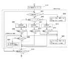
図5は、図4のステップS112の通常送り制御の詳細を示すフローチャートである。なお、以下の処理において、各閾値a,b,c,d(A)は、a>b>c、及びa>dの関係にある。(Normal feed control)
FIG. 5 is a flowchart showing details of the normal feed control in step S112 of FIG. In the following processing, the threshold values a, b, c, and d (A) have a relationship of a>b> c and a> d.
上記ステップS111の処理が終了すると、メイン制御部64は送りモータNG判別部56、マグネット断線検出回路58、横ずれ検出器60等からのNG信号の有無をチェックする(S201)。NG信号有りの場合(S201:Yes)、メイン制御部64は、送りモータ20a及び電気ドリル16を停止させると共に、NG内容に応じてLED表示器68を点灯する(S202)。 When the processing of step S111 is completed, the
一方、NG信号無しの場合(S201:No)、ステップS106、S108で判断された刃物径に基づく設定モードが大、中、小のいずれであったかがメイン制御部64によりチェックされ(S203)、設定モードに応じた制御プログラムが実行される(S204、S211、S213)。例えば大径モードであった場合(S203:大)、大径にあわせた送り速度で制御したり、ドリルモータ46のモータ電流Imに応じて送りを早めたり、遅くしたりする大径用制御プログラムが実行される(S204)。続いて、ドリルモータ46のモータ電流Imと閾値a(A)が比較され(S205)、「モータ電流Im≧閾値a」がメイン制御部64により判断されたとき(S205:Yes)には、過負荷発生を判断して送りモータ20a及び電気ドリル16を停止させると共に、LED表示器68を点灯する(S207)。 On the other hand, when there is no NG signal (S201: No), the
一方、ステップS205において、メイン制御部64により「モータ電流Im<閾値a」が判断されたとき(S205:No)、ドリルモータ46のモータ電流Imは閾値d(A)と比較され(S208)、「モータ電流Im≧閾値d」が判断されたときには(S208:Yes)、切り屑切断のため、送りモータ20aを断続運転する(S209)。この、送りモータ20aの断続運転(S209)は、切り屑が切断されてドリルモータ46の負荷が低減され、ステップS208で「モータ電流Im≧閾値d」がNoとなるまで繰り返される。 On the other hand, when “motor current Im <threshold value a” is determined by the
また、ステップS208において、メイン制御部64により「モータ電流Im<閾値dが判断されたとき(S208:No)、図4で説明したステップS113の処理が実行さ」れ、ここで無負荷が検出されれば(S113:Yes)、更に、ステップS114,S115の処理がメイン制御部64により実行されて穿孔作業が終了することは上述の通りである。 Further, in step S208, the
ステップS203において、メイン制御部64により中径モードであると判断されたとき(S203:中)は、メイン制御部64により、例えば、中径にあわせた送り速度で制御したり、ドリルモータドリル46のモータ電流Imに応じて送りを早めたり、遅くしたりする中径用制御プログラムが実行される(S211)。続いて、メイン制御部64によりモータ電流Imと閾値b(A)が比較され(S212)、「モータ電流Im≧閾値b」が判断されたとき(S212:Yes)には、過負荷発生を判断して送りモータ20a及び電気ドリル16を停止させると共に、LED表示器68を点灯する(S207)。 When it is determined in step S203 that the
また、ステップS203において、メイン制御部64により小径モードであると判断されたとき(S203:小)、メイン制御部64により、例えば、小径にあわせた送り速度で制御したり、ドリルモータ46のモータ電流Imに応じて送りを早めたり、遅くしたりする小径用制御プログラムが実行される(S213)。更に、メイン制御部64によりモータ電流Imと閾値c(A)が比較され、「モータ電流Im≧閾値c」が判断されたとき(S214:Yes)、メイン制御部64により過負荷発生を判断して送りモータ20a及び電気ドリル16を停止させると共に、LED表示器68を点灯する(S207)。 In step S203, when the
更に、メイン制御部64により、ステップS212において「モータ電流<閾値b」が判断されたとき(S212:No)、及びステップ214において「モータ電流<閾値c」が判断されたとき(S214:No)、メイン制御部64により図4で説明したステップ113の処理が実行され、無負荷であることが検出された場合には(S113:Yes)、ステップ114,115の処理がメイン制御部64により実行されて穿孔作業が終了することは上述の通りである。 Furthermore, when “motor current <threshold value b” is determined by the
以上のように、環状刃物24の刃物径を判別し、小径刃物の場合には、ドリル送りを完全停止させることなく、また、送り量が遅すぎることのない制御にすることができる。また、大径の場合は、送り量が大き過ぎると環状刃物24に負荷がかかりすぎ、直ぐに過負荷保護機能が働き停止してしまうため、ステップS208,S209に示すように、送り制御に断続運転を適用して対応する。大径の場合は、これに加えて、電気ドリル16の電流値があるレベルを超えると、ドリル送りを完全停止させることなく、また、送り量が早すぎることのない制御を適用するようにしてもよい。更に、中径刃物については、例えば、刃物径によって、小径刃物の制御あるいは大径刃物と同様の制御を選択でき、中径刃物に合わせた適切な送り量の設定が可能になる。 As described above, the cutter diameter of the
以上説明したように、本実施の形態によれば、環状刃物24の刃物径を検出して大、中、小の径に分類し、それぞれの径に合った値に過負荷検出レベルをセットし、更に送り制御の変更を行うようにしたので、作業性を損なわず刃物寿命及び耐久性を向上できる。また、ドリルモータ46の焼損を防止することができる。 As described above, according to the present embodiment, the blade diameter of the
なお、上記実施の形態においては、制御モードにおいて刃物径を大、中、小の3種類に分けたが、2種類または4種類以上であってもよい。In the above embodiment, the blade diameter is divided into three types of large, medium, and small in thecontrol mode, but it may be two types or four or more types.
10 本体
12 電磁ベース
12a マグネットコイル
14 スライド板
16 電気ドリル
18 ハンドル
20 ドリル送り部
20a モータ
22 スピンドル
24 環状刃物
24a センタピン
26 ブラケット
28 電源スイッチ
30 ロータリスイッチ
34 電気ドリルスイッチ
40 交流電源
42 両波整流器
44 変圧器
46 ドリルモータ
48 ドリルモータ制御部
50 モータ電流検出器
52 モータ電源回路
54 モータ制御部
56 送りモータNG判別部
58 マグネット断線検出回路
60 横ずれ検出器
62 再起動防止検出回路
64 メイン制御部
64a ROM
68 LED表示器
70 電源回路
100 ドリル装置DESCRIPTION OF
68
Claims (5)
Translated fromJapanese前記電気ドリル及び前記ドリル送り部を駆動して前記被加工物を穿孔するドリル装置であって、前記ドリルモータに流れる電流を検出するモータ電流検出器と、
前記ドリルモータの通電を制御する制御部と、
を有し、
前記制御部は、所定のドリル送り速度における前記モータ電流検出器の検出電流に基づいて、穿孔中の前記刃物の径を識別し、前記識別結果に応じて前記刃物径ごとに制御モードを設定することを特徴とするドリル装置。An electric drill that rotationally drives the blade using a drill motor as a drive source, and a drill feed section that reciprocates the electric drill with respect to the workpiece,
A drill device for driving the electric drill and the drill feed unit to drill the workpiece, a motor current detector for detecting a current flowing in the drill motor;
A control unit for controlling energization of the drill motor;
Have
The control unit identifies a diameter of the blade being drilled based on a detection current of the motor current detector at a predetermined drill feed speed, and sets a control mode for each blade diameter according to the identification result. A drilling device characterized by that.
前記制御モードは、該検出電流が該第1の比較値以上の大径モード、該検出電流が該第1の比較値よりも小さく且つ該第2の比較値以上の中径モード、及び該検出電流が該第2の比較値未満の小径モードの3種類であることを特徴とする請求項2に記載のドリル装置。The comparison value is measured using a first comparison value measured using a blade having a predetermined first blade diameter, and a blade having a second blade diameter smaller than the first blade diameter. A second comparison value,
The control mode includes a large-diameter mode in which the detection current is greater than or equal to the first comparison value, a medium-diameter mode in which the detection current is smaller than the first comparison value and greater than or equal to the second comparison value, and the detection The drill apparatus according to claim 2,wherein the current is of three types in a small diameter mode less than the second comparison value .
Priority Applications (7)
| Application Number | Priority Date | Filing Date | Title |
|---|---|---|---|
| JP2007025194AJP4787768B2 (en) | 2007-02-05 | 2007-02-05 | Drilling equipment |
| CN2008800077877ACN101641175B (en) | 2007-02-05 | 2008-02-01 | Drilling rig |
| EP08710714AEP2127790B1 (en) | 2007-02-05 | 2008-02-01 | Drilling apparatus |
| KR1020097016382AKR101066060B1 (en) | 2007-02-05 | 2008-02-01 | Drill unit |
| US12/525,778US20100028093A1 (en) | 2007-02-05 | 2008-02-01 | Drilling apparatus |
| PCT/JP2008/051682WO2008096681A1 (en) | 2007-02-05 | 2008-02-01 | Drilling apparatus |
| TW097104682ATW200936279A (en) | 2007-02-05 | 2008-02-05 | Drilling apparatus |
Applications Claiming Priority (1)
| Application Number | Priority Date | Filing Date | Title |
|---|---|---|---|
| JP2007025194AJP4787768B2 (en) | 2007-02-05 | 2007-02-05 | Drilling equipment |
Publications (2)
| Publication Number | Publication Date |
|---|---|
| JP2008188703A JP2008188703A (en) | 2008-08-21 |
| JP4787768B2true JP4787768B2 (en) | 2011-10-05 |
Family
ID=39681592
Family Applications (1)
| Application Number | Title | Priority Date | Filing Date |
|---|---|---|---|
| JP2007025194AActiveJP4787768B2 (en) | 2007-02-05 | 2007-02-05 | Drilling equipment |
Country Status (7)
| Country | Link |
|---|---|
| US (1) | US20100028093A1 (en) |
| EP (1) | EP2127790B1 (en) |
| JP (1) | JP4787768B2 (en) |
| KR (1) | KR101066060B1 (en) |
| CN (1) | CN101641175B (en) |
| TW (1) | TW200936279A (en) |
| WO (1) | WO2008096681A1 (en) |
Cited By (1)
| Publication number | Priority date | Publication date | Assignee | Title |
|---|---|---|---|---|
| WO2014157463A1 (en) | 2013-03-29 | 2014-10-02 | 日東工器株式会社 | Battery-powered drill |
Families Citing this family (20)
| Publication number | Priority date | Publication date | Assignee | Title |
|---|---|---|---|---|
| US8376667B2 (en)* | 2007-07-27 | 2013-02-19 | Milwaukee Electric Tool Corporation | AC/DC magnetic drill press |
| EP2529867A1 (en)* | 2010-01-29 | 2012-12-05 | Hukuzo Yagisita | Boring device |
| WO2012164875A1 (en)* | 2011-05-27 | 2012-12-06 | 株式会社ナカニシ | Dental handpiece control device |
| US20130287508A1 (en) | 2012-04-25 | 2013-10-31 | Milwaukee Electric Tool Corporation | Magnetic drill press |
| USD681080S1 (en)* | 2012-12-18 | 2013-04-30 | Ting Fong Electric & Machinery Co., Ltd. | Hole drilling machine with magnetic holder |
| JP5977692B2 (en)* | 2013-03-07 | 2016-08-24 | 株式会社神戸製鋼所 | Low rigidity composite material drilling equipment |
| US9669539B2 (en)* | 2014-03-21 | 2017-06-06 | The United States Of America As Represented By The Secretary Of The Navy | Magnetic drill system |
| US9561568B2 (en) | 2014-04-25 | 2017-02-07 | Black & Decker Inc. | Magnetic drill press with alternate power source |
| EP3109008B1 (en)* | 2015-06-24 | 2018-08-15 | Black & Decker Inc. | Magnetic drill press with alternate power source |
| WO2017044357A1 (en)* | 2015-09-09 | 2017-03-16 | Schlumberger Technology Corporation | Tool lifespan parameter detector |
| CN108778651B (en) | 2016-02-03 | 2021-06-18 | 米沃奇电动工具公司 | System and method for configuring a reciprocating saw |
| CH713798A1 (en)* | 2017-05-19 | 2018-11-30 | Reishauer Ag | Machine for fine machining of toothed workpieces and method for measuring parameters of a finishing tool. |
| JP7008715B2 (en)* | 2017-09-29 | 2022-01-25 | 本田技研工業株式会社 | Processing equipment and processing method |
| ES2855140T3 (en) | 2018-03-08 | 2021-09-23 | Stihl Ag & Co Kg Andreas | Procedure for type-dependent operation of an electric drive unit and a system |
| DE202019106916U1 (en)* | 2019-12-12 | 2021-03-15 | C. & E. Fein Gmbh | Magnetic base |
| JP1669958S (en) | 2019-12-26 | 2020-10-12 | ||
| JP1680039S (en) | 2020-03-17 | 2021-03-01 | ||
| JP1680101S (en) | 2020-03-17 | 2021-03-01 | ||
| CN112247208A (en)* | 2020-09-16 | 2021-01-22 | 中车长春轨道客车股份有限公司 | Intelligent punching machine for line passing hole of motor train unit |
| CN114559069A (en)* | 2022-03-22 | 2022-05-31 | 天泽电力(江苏)有限公司 | Track drilling machine and control method thereof |
Family Cites Families (23)
| Publication number | Priority date | Publication date | Assignee | Title |
|---|---|---|---|---|
| KR860000144B1 (en)* | 1981-11-20 | 1986-02-27 | 도시오 미끼야 | Drilling machine with electronic base |
| JPS58177210A (en)* | 1982-04-05 | 1983-10-17 | Nitto Giken Kk | Drill |
| US4540318A (en)* | 1982-07-29 | 1985-09-10 | Robert Bosch, Gmbh | Rotary electrical tool with speed control, especially drill |
| GB2164878B (en)* | 1984-08-27 | 1987-10-21 | Brother Ind Ltd | A machine tool for machining a workpiece by feeding a cutting tool in a series of discrete steps and related method |
| JPS6156810A (en) | 1984-08-27 | 1986-03-22 | Brother Ind Ltd | Machine tool |
| JPS6215004A (en)* | 1985-07-12 | 1987-01-23 | Hitachi Koki Haramachi:Kk | Machine tool diameter detecting device and rotating speed control device for drilling machine and the like |
| US4780654A (en)* | 1986-02-21 | 1988-10-25 | Nitto Kohki Co., Ltd. | Control apparatus for drilling machine |
| US4831364A (en)* | 1986-03-14 | 1989-05-16 | Hitachi Koki Company, Limited | Drilling machine |
| JPS6416348A (en)* | 1988-02-17 | 1989-01-19 | Brother Ind Ltd | Machine tool |
| JPS63283807A (en)* | 1988-04-15 | 1988-11-21 | Nitto Giken Kk | Boring machine |
| JPH0753338B2 (en)* | 1988-12-12 | 1995-06-07 | 日立精工株式会社 | Printed circuit board contour processing method and device |
| GB2235552B (en)* | 1989-06-23 | 1993-06-16 | Nitto Kohki Co | Controller for boring apparatus |
| JP2800570B2 (en)* | 1992-07-16 | 1998-09-21 | 日立工機株式会社 | Automatic drilling machine |
| JPH08252706A (en)* | 1995-03-18 | 1996-10-01 | Hino Motors Ltd | Drilling machine |
| JP3185128B2 (en)* | 1995-12-14 | 2001-07-09 | 株式会社椿本チエイン | Overload protection device |
| US5894095A (en)* | 1997-04-17 | 1999-04-13 | Demali; Gary W. | Mixing drill with speed sensing with multiple preset speeds |
| JP3436899B2 (en) | 1999-09-10 | 2003-08-18 | 義昭 垣野 | Tool abnormality detection device and numerical control device provided with the same |
| DE19945395A1 (en)* | 1999-09-22 | 2001-04-05 | Deckel Maho Gmbh | Monitoring method and device for numerically controlled machine tools |
| JP4060550B2 (en)* | 2001-07-13 | 2008-03-12 | 日東工器株式会社 | Control device for portable electric drill |
| JP4043420B2 (en) | 2003-08-01 | 2008-02-06 | 日東工器株式会社 | Electric drilling device with automatic redrive function |
| CN2706261Y (en)* | 2004-04-05 | 2005-06-29 | 扬州捷利得电动工具有限公司 | Automatic cutting feed type magnetic seat drill |
| CN2799134Y (en)* | 2005-06-30 | 2006-07-26 | 吴彤 | Dual-engine double-controlling magnetic drill |
| WO2007074647A1 (en)* | 2005-12-26 | 2007-07-05 | Nitto Kohki Co., Ltd. | Portable drilling machine |
- 2007
- 2007-02-05JPJP2007025194Apatent/JP4787768B2/enactiveActive
- 2008
- 2008-02-01KRKR1020097016382Apatent/KR101066060B1/ennot_activeExpired - Fee Related
- 2008-02-01USUS12/525,778patent/US20100028093A1/ennot_activeAbandoned
- 2008-02-01WOPCT/JP2008/051682patent/WO2008096681A1/enactiveApplication Filing
- 2008-02-01EPEP08710714Apatent/EP2127790B1/ennot_activeNot-in-force
- 2008-02-01CNCN2008800077877Apatent/CN101641175B/ennot_activeExpired - Fee Related
- 2008-02-05TWTW097104682Apatent/TW200936279A/ennot_activeIP Right Cessation
Cited By (3)
| Publication number | Priority date | Publication date | Assignee | Title |
|---|---|---|---|---|
| WO2014157463A1 (en) | 2013-03-29 | 2014-10-02 | 日東工器株式会社 | Battery-powered drill |
| EP3199278A1 (en) | 2013-03-29 | 2017-08-02 | Nitto Kohki Co., Ltd. | Battery-powered drill |
| EP3254789A1 (en) | 2013-03-29 | 2017-12-13 | Nitto Kohki Co., Ltd. | Battery-operated drilling machine |
Also Published As
| Publication number | Publication date |
|---|---|
| TWI333876B (en) | 2010-12-01 |
| US20100028093A1 (en) | 2010-02-04 |
| EP2127790B1 (en) | 2013-01-09 |
| KR101066060B1 (en) | 2011-09-20 |
| WO2008096681A1 (en) | 2008-08-14 |
| EP2127790A4 (en) | 2012-01-04 |
| CN101641175B (en) | 2011-04-27 |
| KR20090108617A (en) | 2009-10-15 |
| EP2127790A1 (en) | 2009-12-02 |
| JP2008188703A (en) | 2008-08-21 |
| CN101641175A (en) | 2010-02-03 |
| TW200936279A (en) | 2009-09-01 |
Similar Documents
| Publication | Publication Date | Title |
|---|---|---|
| JP4787768B2 (en) | Drilling equipment | |
| CN102883842B (en) | Drilling rig with controller for feed unit | |
| JPS58177210A (en) | Drill | |
| KR100673342B1 (en) | Electric drill device | |
| WO2007074647A1 (en) | Portable drilling machine | |
| JPH09314409A (en) | Punching machine controller | |
| CN102770223B (en) | Mobile Drilling Machine | |
| KR20080025598A (en) | Table Drilling Machine with Safety Device | |
| JP4043420B2 (en) | Electric drilling device with automatic redrive function | |
| JP4077777B2 (en) | Low length electric drill | |
| JP3707656B2 (en) | Automatic feed control device | |
| JP4060550B2 (en) | Control device for portable electric drill | |
| JPS61131807A (en) | Drilling machine | |
| CN114080297B (en) | Portable machine tool | |
| JPS63283807A (en) | Boring machine | |
| KR100708891B1 (en) | Tapping machine automatic control device and control method | |
| JP7261698B2 (en) | Portable machine tool | |
| CN116276824A (en) | Electric tool and control method thereof | |
| JP4628980B6 (en) | Portable drilling machine | |
| WO2020095781A1 (en) | Boring machine | |
| JP2008182066A (en) | Wiring board processing machine | |
| JPS62193715A (en) | Control device for drilling machine able to be fixed to work by electromagnetic base | |
| JP2011031332A (en) | Cutting method of workpiece | |
| JPH11254216A (en) | Magnetic drilling machine | |
| JPH0761597B2 (en) | Core drill automatic feeder |
Legal Events
| Date | Code | Title | Description |
|---|---|---|---|
| A621 | Written request for application examination | Free format text:JAPANESE INTERMEDIATE CODE: A621 Effective date:20090123 | |
| TRDD | Decision of grant or rejection written | ||
| A01 | Written decision to grant a patent or to grant a registration (utility model) | Free format text:JAPANESE INTERMEDIATE CODE: A01 Effective date:20110628 | |
| A01 | Written decision to grant a patent or to grant a registration (utility model) | Free format text:JAPANESE INTERMEDIATE CODE: A01 | |
| A61 | First payment of annual fees (during grant procedure) | Free format text:JAPANESE INTERMEDIATE CODE: A61 Effective date:20110715 | |
| R150 | Certificate of patent or registration of utility model | Ref document number:4787768 Country of ref document:JP Free format text:JAPANESE INTERMEDIATE CODE: R150 | |
| FPAY | Renewal fee payment (event date is renewal date of database) | Free format text:PAYMENT UNTIL: 20140722 Year of fee payment:3 | |
| R250 | Receipt of annual fees | Free format text:JAPANESE INTERMEDIATE CODE: R250 | |
| R250 | Receipt of annual fees | Free format text:JAPANESE INTERMEDIATE CODE: R250 | |
| R250 | Receipt of annual fees | Free format text:JAPANESE INTERMEDIATE CODE: R250 | |
| R250 | Receipt of annual fees | Free format text:JAPANESE INTERMEDIATE CODE: R250 | |
| R250 | Receipt of annual fees | Free format text:JAPANESE INTERMEDIATE CODE: R250 | |
| R250 | Receipt of annual fees | Free format text:JAPANESE INTERMEDIATE CODE: R250 | |
| R250 | Receipt of annual fees | Free format text:JAPANESE INTERMEDIATE CODE: R250 | |
| R250 | Receipt of annual fees | Free format text:JAPANESE INTERMEDIATE CODE: R250 | |
| R250 | Receipt of annual fees | Free format text:JAPANESE INTERMEDIATE CODE: R250 | |
| R250 | Receipt of annual fees | Free format text:JAPANESE INTERMEDIATE CODE: R250 | |
| R250 | Receipt of annual fees | Free format text:JAPANESE INTERMEDIATE CODE: R250 | |
| R250 | Receipt of annual fees | Free format text:JAPANESE INTERMEDIATE CODE: R250 |