JP4785478B2 - Application stopper - Google Patents
Application stopperDownload PDFInfo
- Publication number
- JP4785478B2 JP4785478B2JP2005273887AJP2005273887AJP4785478B2JP 4785478 B2JP4785478 B2JP 4785478B2JP 2005273887 AJP2005273887 AJP 2005273887AJP 2005273887 AJP2005273887 AJP 2005273887AJP 4785478 B2JP4785478 B2JP 4785478B2
- Authority
- JP
- Japan
- Prior art keywords
- head
- contents
- outer skin
- spout
- local region
- Prior art date
- Legal status (The legal status is an assumption and is not a legal conclusion. Google has not performed a legal analysis and makes no representation as to the accuracy of the status listed.)
- Expired - Fee Related
Links
- 239000011248coating agentSubstances0.000claimsdescription14
- 238000000576coating methodMethods0.000claimsdescription14
- 229920001971elastomerPolymers0.000claimsdescription8
- 238000007599dischargingMethods0.000claimsdescription7
- 239000000806elastomerSubstances0.000claimsdescription7
- 238000007789sealingMethods0.000claimsdescription2
- 239000007779soft materialSubstances0.000description3
- 208000003251PruritusDiseases0.000description1
- 239000003795chemical substances by applicationSubstances0.000description1
- 239000003814drugSubstances0.000description1
- 238000001035dryingMethods0.000description1
- 238000005192partitionMethods0.000description1
- 238000007711solidificationMethods0.000description1
- 230000008023solidificationEffects0.000description1
Images


Landscapes
- Containers And Packaging Bodies Having A Special Means To Remove Contents (AREA)
- Closures For Containers (AREA)
Description
Translated fromJapanese本発明は、容器の口部に取り付けられ、塗布すべき部位に直接接触させて内容物を塗布するのに好適な塗布栓に関するものであり、内容物の乾燥、固化を回避して内容物の安定注出を図ろうとするものである。 The present invention relates to a coating stopper that is attached to the mouth of a container and is suitable for coating the contents by directly contacting the portion to be coated, and avoids drying and solidification of the contents. It aims to ensure stable dispensing.
容器の胴体部分をスクイズしてその口部に配置した塗布栓に内容物を供給し、該塗布栓を直接塗布すべき部位に押し当てることによって塗布する容器は、かゆみ止め剤等の薬剤を入れる容器として多用されている。 The container to be applied by squeezing the body part of the container and supplying the contents to the application stopper placed in the mouth and pressing the application stopper directly against the site to be applied puts a medicine such as an anti-itch agent. Often used as a container.
かかる容器に適用される塗布栓としては、内容物を含浸させて塗布するスポンジタイプのもの(例えば、特許文献1参照)や鍼状の突起を複数配置したブラシタイプのもの、あるいはドーム型のヘッドにエラストマーの如き軟質材を離脱可能に被せたもの等、これまでに様々のものが提案されているが、とくに、ドーム型のヘッドにエラストマーを配置した塗布栓は、ヘッドとエラストマーとの相互間(離脱面)において内容物が残存しやすく、その部位で内容物が乾燥、固化した場合に内容物の安定的な供給、塗布が行えないことが想定された。
本発明の課題は、とくに注出口を有するヘッドの表面にエラストマーの如き軟質材を被せた塗布栓において従来生じていた問題を解消し得る新規な塗布栓を提案するところにある。 An object of the present invention is to propose a novel coating plug that can solve the problems that have conventionally occurred in a coating plug in which a surface of a head having a spout is covered with a soft material such as an elastomer.
本発明は、容器内の内容物を通過させる注出口を有するヘッドを備え、該ヘッドを塗布すべき領域に対向させて内容物を塗布する塗布栓であって、
前記ヘッドに、その表面を覆い隠す軟材質の外皮体を配設してなり、
該外皮体は、前記注出口よりも外側に配置されて当該注出口を経た内容物を外界へ排出する少なくとも1つの開孔と、この開孔を含む局所領域を薄肉化すると共に弾性変形させることができるようにして前記ヘッドとの相互間に内部空間を区画形成し、その壁面において内容物を一旦衝突させたのち該開孔へと誘導する迂回経路を有することを特徴とする塗布栓である。
The present invention is an application plug that includes a head having a spout for allowing the contents in a container to pass therethrough, and applies the contents so that the head faces the area to be applied,
The head is provided with a soft outer skin covering the surface,
The outer skin body isdisposed outside the spout, and at least one opening for discharging the contents that have passed through thespout to the outside, and a local region including the opening is thinned andelastically deformed. An application plug characterized in that an internal space is defined between the head and the headso that the contents can collide once on the wall surface and then guide to the opening. is there.
上記の構成になる塗布栓においては、前記外皮体をヘッドとともに覆い隠すカバーキャップを備えることが可能で、この場合には、該カバーキャップに、外皮体の薄肉化された局所領域をヘッドの表面に押し付けて注出口を閉塞させる凸部を設けるのが好ましい。 In the application plug having the above-described configuration, a cover cap that covers the outer skin body together with the head can be provided. In this case, the thinned local region of the outer skin body is provided on the surface of the head on the cover cap. It is preferable to provide a convex portion that is pressed against the outlet to close the outlet.
また、前記薄肉化された局所領域は、内容物の排出にかかる圧力が付加された場合には逆アール部を起点とする反転により迂回経路を形成するが、内容物の排出にかかる圧力が付加されない場合には逆アール部を起点にして前記ヘッドの表面に弾性接触してシール状態を維持するものが望ましく、前記外皮体はとくにエラストマーが有利に適合する。 In addition, the thinned local region forms a detour path by reversal starting from the reverse radius when the pressure for discharging the contents is applied, but the pressure for discharging the contents is added. If not, it is desirable to maintain a sealed state by elastically contacting the head surface starting from the inverted rounded portion, and the outer shell body is particularly suitable for an elastomer.
外皮体の開孔を含む局所領域を薄肉化し該外皮体とヘッドとの相互間に内部空間を区画形成したため、内容物が通過する十分な広さの迂回経路が確保され内容物の安定的な供給が可能となる。 Since the local area including the opening of the outer skin is thinned and the internal space is partitioned between the outer skin and the head, a sufficiently wide detour path through which the content passes is secured and the content is stable. Supply becomes possible.
ヘッドの注出口から出た内容物は、迂回経路を形成する壁面に一旦衝突したのち、外皮体の開孔を通して外部へと排出されることから内容物の噴出速度を減ずることができる。 The contents exiting from the spout of the head once collide with the wall surface forming the detour path, and then are discharged to the outside through the opening of the outer skin, so that the ejection speed of the contents can be reduced.
以下、図面を用いて本発明をより具体的に説明する。
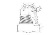
図1は本発明に従う塗布栓の実施の形態を示した図であり、図における1はチューブ等、スクイズが可能な容器、2は容器1の口部1aに一体的に成形された例で示した塗布栓である。Hereinafter, the present invention will be described more specifically with reference to the drawings.
FIG. 1 is a view showing an embodiment of an application plug according to the present invention. In the figure, 1 is a tube or the like, a squeezable container, and 2 is an example in which the container 1 is integrally formed with the mouth 1a. It is a coating stopper.
塗布栓2は注出口tを有するドーム型のヘッド2aと、このヘッド2aの表面を覆い隠す軟材質(エラストマーやゴム等)の外皮体2bからなっており、該外皮体2bはヘッド2aの基部でアンダーカットCを介して着脱可能に取り付けられている。 The
また、3は外皮体2bに設けられヘッド2aの注出口tを経た内容物を外界へ排出する開孔、4はヘッド2aと外皮体2bの相互間に設けられた迂回経路である。この迂回経路4は開孔3を含む外皮体2bの局所領域mを薄肉化して内部空間を区画形成するもので、薄肉化された局所領域mは弾性変位することができるようになっている。 Further, 3 is an opening provided in the
上記の構成になる塗布栓は、迂回経路4によって常に内部空間が形成されており、そこに内容物が残存して乾燥、固化することがあっても内容物を通過させるのに十分な通路を確保することが可能となるため、内容物を安定的な供給と塗布が可能となる。 In the coating plug having the above-described configuration, an internal space is always formed by the detour path 4, and a passage sufficient to allow the contents to pass therethrough may be dried and solidified there. Since it can be ensured, the contents can be supplied and applied stably.
また、容器1の胴体をスクイズするに当たって不用意に過大な加圧力が付加される場合においても、注出口tから噴出した内容物は迂回経路4の壁面に一旦衝突するので、適度な速度に減速される。 Further, even when excessive pressure is applied inadvertently when the body of the container 1 is squeezed, the contents spouted from the spout t once collide with the wall surface of the detour path 4, so that the speed is reduced to an appropriate speed. Is done.
本発明に従う塗布栓は、図2に示すようなカバーキャップ5を備え付けておくことができる。この場合に、カバーキャップ5に凸部5aを設けて外皮体2bの局所領域mをヘッド2aの表面に押し付けて注出口tを閉塞させておくのがよく、収納状態において容器が転倒することがあっても内容物がこぼれ出ることがない。 The application plug according to the present invention can be provided with a
図3は本発明に従う塗布栓の他の実施の形態を示した図である。
この塗布栓は、局所領域mを弾性力を付与する逆アール部が環状に形成されており、内容物の排出にかかる圧力が付加されていない場合には逆アール部6aを起点にして局所領域mがヘッド2の表面に接触してシール状態を維持するが、内容物の排出にかかる圧力が付加された場合には逆アール部6aを起点にして局所領域mが図4に示すように反転して迂回経路4を形成する。前記各実施形態において、図示したごとく、注出口tは外方に突出した円筒状とすることが、シール性の面から好ましい(密着性が高まる)。FIG. 3 is a view showing another embodiment of the application plug according to the present invention.
In this application plug, a reverse radius portion that gives elastic force to the local region m is formed in an annular shape, and when no pressure is applied to discharge the contents, the local region starts from the
かかる構成の塗布栓は、カバーキャップ5を装着しない状態で容器が転倒しても内容物が簡単に流出することがない利点がある。 The coating plug having such a configuration has an advantage that the contents do not easily flow out even if the container falls without the
内容物を安定的に排出して塗布できる塗布栓が提供できる。 It is possible to provide an application stopper that can discharge and apply the contents stably.
1 容器
1a 口部
2 塗布栓
2a ヘッド
2b 外皮体
3 開孔
4 迂回経路
5 カバーキャップ
6a 逆アール部
C アンダーカット
m 局所領域
t 注出口1 container
2a head
6a Reverse radius C Undercut m Local area t Outlet
Claims (4)
Translated fromJapanese前記ヘッドに、その表面を覆い隠す軟材質の外皮体を配設してなり、
該外皮体は、前記注出口よりも外側に配置されて当該注出口を経た内容物を外界へ排出する少なくとも1つの開孔と、この開孔を含む局所領域を薄肉化すると共に弾性変形させることができるようにして前記ヘッドとの相互間に内部空間を区画形成し、その壁面において内容物を一旦衝突させたのち該開孔へと誘導する迂回経路を有することを特徴とする塗布栓。An application stopper comprising a head having a spout for allowing the contents in the container to pass therethrough, and applying the contents so that the head faces the area to be applied,
The head is provided with a soft outer skin covering the surface,
The outer skin body isdisposed outside the spout, and at least one opening for discharging the contents that have passed through thespout to the outside, and a local region including the opening is thinned andelastically deformed. An application stopper characterized in that an internal space is defined between the head and the headso that the contents can collide with each other on the wall surface and then have a bypass route to guide the opening.
The coating plug according to any one of claims 1 to 3, wherein the outer skin is an elastomer.
Priority Applications (1)
| Application Number | Priority Date | Filing Date | Title |
|---|---|---|---|
| JP2005273887AJP4785478B2 (en) | 2005-09-21 | 2005-09-21 | Application stopper |
Applications Claiming Priority (1)
| Application Number | Priority Date | Filing Date | Title |
|---|---|---|---|
| JP2005273887AJP4785478B2 (en) | 2005-09-21 | 2005-09-21 | Application stopper |
Publications (2)
| Publication Number | Publication Date |
|---|---|
| JP2007084094A JP2007084094A (en) | 2007-04-05 |
| JP4785478B2true JP4785478B2 (en) | 2011-10-05 |
Family
ID=37971505
Family Applications (1)
| Application Number | Title | Priority Date | Filing Date |
|---|---|---|---|
| JP2005273887AExpired - Fee RelatedJP4785478B2 (en) | 2005-09-21 | 2005-09-21 | Application stopper |
Country Status (1)
| Country | Link |
|---|---|
| JP (1) | JP4785478B2 (en) |
Families Citing this family (2)
| Publication number | Priority date | Publication date | Assignee | Title |
|---|---|---|---|---|
| SG195034A1 (en)* | 2011-05-23 | 2013-12-30 | Toko Yakuhin Kogyo Kk | Application container |
| JP6952991B2 (en)* | 2017-07-28 | 2021-10-27 | キタノ製作株式会社 | Container with coating body |
Family Cites Families (4)
| Publication number | Priority date | Publication date | Assignee | Title |
|---|---|---|---|---|
| JPS4721161Y1 (en)* | 1969-07-11 | 1972-07-13 | ||
| FR2736623B1 (en)* | 1995-07-10 | 1997-08-22 | Oreal | PACKAGING AND DISTRIBUTION DEVICE FOR A LIQUID, GELIFIED OR PASTE PRODUCT WITH DOME-SHAPED APPLICATOR |
| JP4147392B2 (en)* | 2003-01-14 | 2008-09-10 | ライオン株式会社 | Bleaching detergent product for coating |
| JP4301365B2 (en)* | 2003-10-31 | 2009-07-22 | 株式会社吉野工業所 | Quantitative dispensing cap |
- 2005
- 2005-09-21JPJP2005273887Apatent/JP4785478B2/ennot_activeExpired - Fee Related
Also Published As
| Publication number | Publication date |
|---|---|
| JP2007084094A (en) | 2007-04-05 |
Similar Documents
| Publication | Publication Date | Title |
|---|---|---|
| JP4085091B2 (en) | Applicator package with disposable applicator pad assembly | |
| JP3910059B2 (en) | Delamination container | |
| CN102822066A (en) | Fluid substance storage container and its cover | |
| JP4542867B2 (en) | Equipment for packaging and applying substances | |
| JP6059139B2 (en) | Application container | |
| WO2005053457A1 (en) | Container with applicator | |
| JP4785478B2 (en) | Application stopper | |
| JP5238378B2 (en) | cap | |
| JPH08119306A (en) | Discharge opening structure for refill container | |
| JP2019064680A (en) | Cap for container | |
| JP5296625B2 (en) | Cosmetic container | |
| JPH10194308A (en) | Squeeze out container | |
| WO2005089588A1 (en) | Container with applicator | |
| JP5554613B2 (en) | Contents extrusion container | |
| JP3993487B2 (en) | Fluid tube type container | |
| JPH11138086A (en) | Liquid application container | |
| JP4263901B2 (en) | Valve mechanism | |
| JP2012012056A (en) | Application container | |
| JP6019584B2 (en) | Tube container | |
| JP2011084282A (en) | Fluid push-out container | |
| JP4756955B2 (en) | Discharge cap | |
| JP7427340B2 (en) | Container cap and its manufacturing method | |
| JP2004210351A (en) | Liquid spout container | |
| JP4384938B2 (en) | Application container | |
| JP7193293B2 (en) | Dispensing spouts and packaging containers |
Legal Events
| Date | Code | Title | Description |
|---|---|---|---|
| A621 | Written request for application examination | Free format text:JAPANESE INTERMEDIATE CODE: A621 Effective date:20080326 | |
| A977 | Report on retrieval | Free format text:JAPANESE INTERMEDIATE CODE: A971007 Effective date:20101115 | |
| A131 | Notification of reasons for refusal | Free format text:JAPANESE INTERMEDIATE CODE: A131 Effective date:20101124 | |
| RD03 | Notification of appointment of power of attorney | Free format text:JAPANESE INTERMEDIATE CODE: A7423 Effective date:20110119 | |
| A131 | Notification of reasons for refusal | Free format text:JAPANESE INTERMEDIATE CODE: A131 Effective date:20110308 | |
| A521 | Written amendment | Free format text:JAPANESE INTERMEDIATE CODE: A523 Effective date:20110506 | |
| RD03 | Notification of appointment of power of attorney | Free format text:JAPANESE INTERMEDIATE CODE: A7423 Effective date:20110506 | |
| TRDD | Decision of grant or rejection written | ||
| A01 | Written decision to grant a patent or to grant a registration (utility model) | Free format text:JAPANESE INTERMEDIATE CODE: A01 Effective date:20110712 | |
| A01 | Written decision to grant a patent or to grant a registration (utility model) | Free format text:JAPANESE INTERMEDIATE CODE: A01 | |
| A61 | First payment of annual fees (during grant procedure) | Free format text:JAPANESE INTERMEDIATE CODE: A61 Effective date:20110712 | |
| R150 | Certificate of patent or registration of utility model | Free format text:JAPANESE INTERMEDIATE CODE: R150 | |
| FPAY | Renewal fee payment (event date is renewal date of database) | Free format text:PAYMENT UNTIL: 20140722 Year of fee payment:3 | |
| LAPS | Cancellation because of no payment of annual fees |