JP4785170B2 - Medical guide wire and molding method thereof - Google Patents
Medical guide wire and molding method thereofDownload PDFInfo
- Publication number
- JP4785170B2 JP4785170B2JP2003174171AJP2003174171AJP4785170B2JP 4785170 B2JP4785170 B2JP 4785170B2JP 2003174171 AJP2003174171 AJP 2003174171AJP 2003174171 AJP2003174171 AJP 2003174171AJP 4785170 B2JP4785170 B2JP 4785170B2
- Authority
- JP
- Japan
- Prior art keywords
- guide wire
- wire
- core wire
- plug
- coil spring
- Prior art date
- Legal status (The legal status is an assumption and is not a legal conclusion. Google has not performed a legal analysis and makes no representation as to the accuracy of the status listed.)
- Expired - Fee Related
Links
Images

Classifications
- A—HUMAN NECESSITIES
- A61—MEDICAL OR VETERINARY SCIENCE; HYGIENE
- A61M—DEVICES FOR INTRODUCING MEDIA INTO, OR ONTO, THE BODY; DEVICES FOR TRANSDUCING BODY MEDIA OR FOR TAKING MEDIA FROM THE BODY; DEVICES FOR PRODUCING OR ENDING SLEEP OR STUPOR
- A61M25/00—Catheters; Hollow probes
- A61M25/01—Introducing, guiding, advancing, emplacing or holding catheters
- A61M25/09—Guide wires
- A61M2025/09058—Basic structures of guide wires
- A61M2025/09083—Basic structures of guide wires having a coil around a core
- A—HUMAN NECESSITIES
- A61—MEDICAL OR VETERINARY SCIENCE; HYGIENE
- A61M—DEVICES FOR INTRODUCING MEDIA INTO, OR ONTO, THE BODY; DEVICES FOR TRANSDUCING BODY MEDIA OR FOR TAKING MEDIA FROM THE BODY; DEVICES FOR PRODUCING OR ENDING SLEEP OR STUPOR
- A61M25/00—Catheters; Hollow probes
- A61M25/01—Introducing, guiding, advancing, emplacing or holding catheters
- A61M25/09—Guide wires
- A61M2025/09175—Guide wires having specific characteristics at the distal tip
Landscapes
- Health & Medical Sciences (AREA)
- Life Sciences & Earth Sciences (AREA)
- Biophysics (AREA)
- Pulmonology (AREA)
- Engineering & Computer Science (AREA)
- Anesthesiology (AREA)
- Biomedical Technology (AREA)
- Heart & Thoracic Surgery (AREA)
- Hematology (AREA)
- Animal Behavior & Ethology (AREA)
- General Health & Medical Sciences (AREA)
- Public Health (AREA)
- Veterinary Medicine (AREA)
- Media Introduction/Drainage Providing Device (AREA)
Description
Translated fromJapanese【0001】
【発明の属する技術分野】
本発明は、心臓血管系内等にカテーテルを導入する際に用いる医療用ガイドワイヤと、その成形方法に関するものである。
【0002】
【従来の技術】
血管造影を目的として、極細可撓性管体のカテーテルを血管内挿入したり、または冠状動脈の閉塞部位の治療にバルーンカテーテルを血管内に挿入するのに際し、そのカテーテルの挿入を安全確実にするために用いる可撓性線状体の医療用ガイドワイヤ(以下、単にガイドワイヤという)は、特許文献1等に示される公知例がある。
【0003】
詳しくは、この公知のガイドワイヤ1Bは(図2参照)可撓性極細線のワイヤ主部2から成る極細線条形態にして曲りくねった複雑な径路の血管・分岐血管に前端部分8から挿入して体外に位置する手元部9を押し・引き・回転させながら血管内へ挿入進行させるので、高度の機械的性質が必要であり、血管内への先導挿入部分となる前端部分8は特段の高柔軟性と屈曲変形からの良好な復元性が必要になる。
【0004】
そこで、特許文献1等の従来のガイドワイヤ1Bは、主体のワイヤ主部2の前端部分を細径のコア線3に形成してコイルばね4に嵌装すると共に、このコア線3に以下に述べるロー付け工法による先導栓部10が設けられ、この先導栓部10は「コイルばね4に接合する栓体基部5」と「この栓体基部5と一体にしてコイルばね4の前端に膨隆する先丸切欠球状の膨隆部6」を備えた形状を有している。
【0005】
そして、この先導栓部10は(図2(B)参照)コア線3の前端に「ハンダこてH」上で溶融したロー材Rを溶着して形成したり、別体の先導栓部10を、公知のレーザースポット溶接工法によってコイルばね4に溶着して形成されている。
【0006】
【特許文献1】
特公平4−25024号公報(要約、図1)
【0007】
【発明が解決しようとする課題】
以上の公知例のガイドワイヤ1Bは、各溶接工法等による先導栓部10の形成加工の際の加熱によって、先導栓部10に続くコア線3の若干部分が焼鈍されて引張り強度が低下するので、屈曲した細い血管狭窄部位で「栓体基部5に続くコア線3」の細径部が破断し易い難点がある。
【0008】
本発明は以上の従来技術の難点を解消するガイドワイヤを提供するものである。
【0009】
【課題を解決するための手段】
以上の技術課題を解決する本発明の請求項1に係る医療用ガイドワイヤは、可撓性線条体のワイヤ主部と、そのワイヤ主部の先端部分のコア線と、そのコア線に嵌装されたコイルばねと、前記コア線の前端に形成された、前端が大径部を成す截頭円錐形状の膨径補強部と、その膨径補強部の前端に形成された、外周が前記コイルばねの内側に接合する栓体基部と、その栓体基部の前端に形成された、前記コイルばねの前端に膨隆する膨隆部から成る先導栓部とを備えたことを特徴とする。
【0010】
また、請求項2に係る医療用ガイドワイヤは、請求項1に記載の医療用ガイドワイヤにおいて、前記先導栓部の全長が0.5耗以下であることを特徴とする。
【0011】
即ち、前記構成の本発明のガイドワイヤは、先導栓部10の溶接工法による熱影響によるコア線3の機械的強度劣化を「当該部分のコア線の断面積を増加させる前記膨径補強部の補強形状」によって防止し、ガイドワイヤ先端部分の必要機械的特性の安定確保を図る思想を特徴とするものである。
【0012】
そして、前記構成の本発明の医療用ガイドワイヤの成形方法は、前記先導栓部の栓体基部を「溶接工法によることなく前記ワイヤ主部の素材を機械加工することによって成形し」前記膨隆部を溶接工法によって成形するときの熱影響を、その栓体基部によって吸収して「細径の前記コア線への熱影響を的確に防止」し、該コア線の機械的性質の安定確保を図る思想を特徴にしている。
【0013】
そして、前記構成による特有作用のさらなる安定向上を図る技術意図から前記膨径補強部の横断面積をコア線の細径部の横断面積の1.5倍以上(好ましくは2.5〜3.0倍)にしたり、該膨径補強部の全形を截頭円錐形状または楕円形横断面形状・長円形横断面形状にしたり、さらに、前記成形方法における前記栓体基部の長さを0.4粍以上に設定する等の態様を採択する。
【0014】
【作用】
前記構成の本発明のガイドワイヤは、先導栓部10の後方に引き出すコア線3の若干部分に前記膨径補強部が存在するので、先導栓部10の溶接工法成形時の熱影響を受けるコア線3の当該部位の引張り強度は、その膨径補強によって「熱影響による機械的性質の低下」を充分に補強し、血管内挿入使用時の当該部分の引張り強度が、必要にして充分に確保できる。そして、その膨径補強部を前記態様の截頭円錐形状にすると、機械的強度補強が長さ方向に漸増・漸減の徐変形態となるので、コア線3の長さ方向の強度変化が円滑にして良好な機能が安定する。
【0015】
そして、前記構成の本発明のガイドワイヤの成形方法は、栓体基部がコア線の前端に予め機械加工形成されているので、溶接工法による先導栓部の形成が特段に簡易化・能率化すると共に、その栓体基部によって、前記膨隆部の溶接工法成形の熱影響を吸収してコア線の強度劣化をもたらす熱影響を的確に防止することができる。
【0016】
【発明の実施の形態】
まず、図1(A)を参照して本発明1実施形態のガイドワイヤ1Aを説明する。即ち、可撓性線条体のワイヤ主部2の先端部分を細径にしたコア線3にコイルばね4を嵌装すると共に、コア線3の前端に膨径してコイルばね4の内側と接合または近接する栓体基部5と、この栓体基部5と一体にしてコイルばね4の前端に膨隆する「切欠球体形状の膨隆部6」から成る先導栓部10を備えたガイドワイヤ1において、コア線3の先端部位の若干長が「截頭円錐形状にして大径部が栓体基部5と接合一体化する膨径補強部11」に設定されている。
【0017】
なお、この実施形態の先導栓部10は、ワイヤ主部2の素線を所要形状にセンターレス研磨加工して所要長に切断した「膨径補強部11を設けたコア線3つきワイヤ主部2」の先端部分にコイルばね4を嵌装セットし、しかるのち、TIG溶接工法によって先導栓部10が形成設定される。
【0018】
そして、この実施形態のガイドワイヤ1Aの寸法諸元は、「コア線3の細径部分の直径D1=0.06粍、膨径補強部11の長さL1=0.4粍、膨径補強部11の大径部の直径D2=0.11粍、栓体基部5の長さL2=0.3粍、膨隆部6の高さH=0.3粍」である。
【0019】
以上の実施形態のものは表1に示す補強形態となり、コア線3と栓体基部5との接合部位の溶接熱による強度低下を充分に補強して応分の機械的強度が確保される。
【0020】
【表1】
なお、本発明の膨径補強部11を設けた医療用ガイドワイヤ1Aは、膨径補強部11の最大横断面積がコア線の細径部の横断面積の2.5倍以上に設定したり、膨径 補強部11の長さを0.4粍以上確保すると、前記の熱影響劣化の防止機能が安定する。
【0022】
続いて図1(B)を参照して本発明のガイドワイヤ成形方法の1実施形態と、それによるガイドワイヤ1Aの構造を説明する。即ち、この図1(B)に示すガイドワイヤ1Aは同じく栓体基部5と膨隆部6から成る先導栓部10を設けたものにおいて、コア線3の先端部分を「センターレス研磨等の機械加工手段」によって「先導栓部10の栓体基部5」を一体に連設したコア線3Aに成し、このコア線3Aをコイルばね4に嵌装セットし、しかるのち、TIG溶接工法によって「栓体基部5に切欠円球形状の膨隆部6」を形成して先導栓部10に成す形状と工法に成っている。
【0023】
そして、この図1(B)実施形態のものは栓体基部5の長さL2=0.4〜0.7粍にして「TIG溶接の熱影響がコア線3に及ばない少くとも0.4粍以上の長さ」に設定されている。なお、コア線3の直径D1 =0.06粍、膨隆部6の高さH=0.3粍、膨隆部6の直径D3=0.345粍、の諸元であり、栓体基部5とコア線3は応力集中を防止する曲面接合形態に形成されている。
【0024】
以上の実施形態のガイドワイヤ1Aは、前記の作用がある。即ち、栓体基部5はコア線3の素材を機械加工して予め形成され、膨隆部6のみが溶接工法によって形成されるので、その溶接工法の熱影響はコア線3の細径部に及ぶことなく、コア線3の熱影響焼鈍の不良が的確に防止できる。そして、先導栓部10の全長を0.5粍以下にすると、ガイドワイヤ1Aの先端部分の高可撓性が確保され、屈曲細管血管への深部挿入性が良好に安定する。
【0025】
なお、図1(A)実施形態のガイドワイヤ1Aの膨径補強部11と、図1(B)実施形態の栓体基部5の長さは、いずれも概ね0.4粍以上確保すれば、「コア線3の有害な硬直化をもたらさずに溶接熱によるコア線3の細径部の機械的性質の低下を生ずる有害な熱影響」は的確に防止できる。
【0026】
以上の図1(A)(B)に示す実施形態のガイドワイヤ1Aは、コア線3の先端部位の機械的強度が「過剰・不足になることなく必要にして充分」に確保され、屈曲細管深部への挿入進行に際して折損したり異常曲りを生ずることなく良好なガイドワイヤ性能が安定確保され、ガイドワイヤを用いる諸治療が円滑かつ能率的にできる。
【0027】
そして、本発明のガイドワイヤの成形方法は前記のとおり、溶接工法によって先導栓部10を形成するガイドワイヤの成形能率が特段に向して、安価良質のガイドワイヤの量産提供ができる特有の作用効果がある。
【0028】
なお、本発明のガイドワイヤ1Aは前記の実施形態に限定されず、膨径補強部11は前記截頭円錐形状以外の円柱形状・角柱形状等または段落0013に示す楕円形状・長円形状でも良く、図1(B)に示すガイドワイヤ1Aに、膨径補強部11を設ける形態にすることがある。
【0029】
【発明の効果】
以上の説明のとおり本発明の医療用ガイドワイヤは、溶接工法等によって先導栓部を形成するものにおいて、血管へ挿入先導する先端部位の機械的性質が良好に安定する高品質・高性能にして、当該治療性を向上する。
【0030】
そして、本発明の医療用ガイドワイヤの成形方法は、前記の高品質・高性能の医療用ガイドワイヤを安価に量産提供する。以上の有用な諸効果がある。
【図面の簡単な説明】
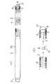
【図1】本発明1実施形態の医療用ガイドワイヤの構造と、本発明の医療用ガイドワイヤの成形方法の1実施形態を示し、(A)はその構造説明の正面図、(B)はその構造説明と成形方法説明の部分正面図
【図2】従来の医療用ガイドワイヤ示し、(A)はその全体正面図、(B)はその成形方法の説明図
【符号の説明】
1A 本発明の医療用ガイドワイヤ
1B 従来の医療用ガイドワイヤ
2 ワイヤ主部
3 コア線
4 コイルばね
5 栓体基部
6 膨隆部
8 先端部分
9 手元部
10 先導栓部
11 膨径補強部[0001]
BACKGROUND OF THE INVENTION
The present invention relates to a medical guide wire used when a catheter is introduced into the cardiovascular system and the like, and a molding method thereof.
[0002]
[Prior art]
For the purpose of angiography, when inserting a catheter of ultra-fine flexible tube into the blood vessel or when inserting a balloon catheter into the blood vessel for the treatment of the occluded site of the coronary artery, ensure that the catheter is inserted safely As a flexible linear medical guide wire used for this purpose (hereinafter simply referred to as a guide wire), there is a known example shown in Patent Document 1 and the like.
[0003]
In detail, this known guide wire 1B (see FIG. 2) is inserted from the front end portion 8 into a blood vessel / branch vessel of a complicated path that is wound in the form of a fine wire composed of a wire
[0004]
Therefore, in the conventional guide wire 1B of Patent Document 1 and the like, the front end portion of the main wire
[0005]
The leading plug portion 10 (see FIG. 2B) is formed by welding the solder material R melted on the “soldering iron H” to the front end of the
[0006]
[Patent Document 1]
Japanese Patent Publication No. 4-25024 (summary, Fig. 1)
[0007]
[Problems to be solved by the invention]
Since the guide wire 1B of the above known example is heated at the time of forming the leading
[0008]
The present invention provides a guide wire that solves the above-mentioned problems of the prior art.
[0009]
[Means for Solving the Problems]
Amedical guide wire accordingto claim 1 of the present invention that solves the above technical problem includesa wire main portion of a flexible linear body, a core wire at a tip portion of the wire main portion, and a fitting to the core wire. A coil spring mounted, a frustoconical bulged reinforcing portion formed at the front end of the core wire, the front end forming a large diameter portion, and an outer periphery formed at the front end of the bulged reinforcing portion. A plug base portion joined to the inside of the coil spring, and a leading plug portion formed at the front end of the plug base portion, which is a bulge portion bulging at the front end of the coil spring, are provided.
[0010]
The medical guide wire according to
[0011]
In other words, the guide wire of the present invention having the above-described configuration can reduce the mechanical strength of the
[0012]
And, the method for molding the medical guide wire of the present invention having the above-described configuration is characterized in that the plug base portion of the leading plug portion is formed by machining the material of the wire main portion without using a welding method. The heat effect when molding the steel wire by the welding method is absorbed by the base of the plug body to "prevent the heat effect on the core wire having a small diameter" and to ensure the stability of the mechanical properties of the core wire. It is characterized by thought.
[0013]
And from the technical intention of further improving the specific action by the above-mentioned configuration, the cross-sectional area of the bulging reinforcing portion is 1.5 times or more (preferably 2.5 to 3.0) of the cross-sectional area of the small-diameter portion of the core wire. And the entire shape of the swelled reinforcing portion is a frustoconical shape or an elliptical cross-sectional shape / oval cross-sectional shape, and the length of the plug base in the molding method is 0.4. Adopt a mode such as setting more than 等.
[0014]
[Action]
In the guide wire of the present invention having the above-described structure, since the expanded diameter reinforcing portion exists in a part of the
[0015]
In the guide wire molding method of the present invention having the above-described configuration, since the plug base is machined and formed in advance at the front end of the core wire, the formation of the lead plug by the welding method is greatly simplified and streamlined. At the same time, the plug base portion absorbs the heat effect of the welding method forming of the bulged portion and can accurately prevent the heat effect that causes the strength deterioration of the core wire.
[0016]
DETAILED DESCRIPTION OF THE INVENTION
First, a
[0017]
The
[0018]
The dimensions of the
[0019]
The thing of the above embodiment becomes a reinforcement form shown in Table 1, and fully strengthens the strength fall by the welding heat of the junction part of the
[0020]
[Table 1]
In the
[0022]
Next, with reference to FIG. 1B, an embodiment of the guide wire forming method of the present invention and the structure of the
[0023]
In the embodiment of FIG. 1 (B), the length L2 of the
[0024]
The
[0025]
In addition, if the length of the expansion
[0026]
In the
[0027]
As described above, the guide wire molding method of the present invention has a specific effect that the molding efficiency of the guide wire for forming the
[0028]
Note that the
[0029]
【The invention's effect】
As described above, the medical guide wire according to the present invention forms a leading plug portion by a welding method or the like, and has a high quality and high performance in which the mechanical properties of the distal end portion leading to the blood vessel are well stabilized. , Improve the therapeutic properties.
[0030]
The method for forming a medical guide wire according to the present invention provides the high-quality and high-performance medical guide wire at low cost for mass production. There are the above useful effects.
[Brief description of the drawings]
FIG. 1 shows a structure of a medical guide wire according to an embodiment of the present invention and an embodiment of a method for forming a medical guide wire according to the present invention. FIG. 1 (A) is a front view of the structure description, and FIG. FIG. 2 shows a conventional medical guide wire, (A) is an overall front view thereof, and (B) is an explanatory view of the molding method.
DESCRIPTION OF
Claims (2)
Translated fromJapaneseそのワイヤ主部の先端部分のコア線と、
そのコア線に嵌装されたコイルばねと、
前記コア線の前端に形成された、前端が大径部を成す截頭円錐形状の膨径補強部と、
その膨径補強部の前端に形成された、外周が前記コイルばねの内側に接合する栓体基部と、
その栓体基部の前端に形成された、前記コイルばねの前端に膨隆する膨隆部から成る先導栓部と
を備えたことを特徴とする医療用ガイドワイヤ。A wire main portion of a flexible filament;
A core wire at the tip of the wire main part;
A coil spring fitted to the core wire;
Formed at the front end of the core wire, the front end of the cone-shaped expansion reinforcement part having a large diameter part; and
A plug base portion formed on the front end of the swelled reinforcing portion, the outer periphery of which is joined to the inside of the coil spring;
A leading plug portion formed at a front end of the plug base portion and formed by a bulging portion that bulges at the front end of the coil spring;
Medical guide wirecomprising the.
Priority Applications (1)
| Application Number | Priority Date | Filing Date | Title |
|---|---|---|---|
| JP2003174171AJP4785170B2 (en) | 2003-06-19 | 2003-06-19 | Medical guide wire and molding method thereof |
Applications Claiming Priority (1)
| Application Number | Priority Date | Filing Date | Title |
|---|---|---|---|
| JP2003174171AJP4785170B2 (en) | 2003-06-19 | 2003-06-19 | Medical guide wire and molding method thereof |
Publications (2)
| Publication Number | Publication Date |
|---|---|
| JP2005006868A JP2005006868A (en) | 2005-01-13 |
| JP4785170B2true JP4785170B2 (en) | 2011-10-05 |
Family
ID=34097727
Family Applications (1)
| Application Number | Title | Priority Date | Filing Date |
|---|---|---|---|
| JP2003174171AExpired - Fee RelatedJP4785170B2 (en) | 2003-06-19 | 2003-06-19 | Medical guide wire and molding method thereof |
Country Status (1)
| Country | Link |
|---|---|
| JP (1) | JP4785170B2 (en) |
Cited By (1)
| Publication number | Priority date | Publication date | Assignee | Title |
|---|---|---|---|---|
| WO2019016877A1 (en) | 2017-07-19 | 2019-01-24 | 朝日インテック株式会社 | GUIDING WIRE |
Families Citing this family (5)
| Publication number | Priority date | Publication date | Assignee | Title |
|---|---|---|---|---|
| JP4913198B2 (en) | 2009-10-27 | 2012-04-11 | 株式会社パテントストラ | Medical guide wire, method for manufacturing medical guide wire, assembly of medical guide wire, microcatheter and guiding catheter, and assembly of medical guide wire, balloon catheter and guiding catheter |
| US12048818B2 (en) | 2020-07-05 | 2024-07-30 | New Wave Endo-Surgical Corp. | Handheld elongate medical device advancer and related systems, devices and methods |
| USD1084319S1 (en) | 2021-07-06 | 2025-07-15 | New Wave Endo-Surgical Corp. | Medical elongate advancer |
| USD1002009S1 (en) | 2021-08-31 | 2023-10-17 | New Wave Endo-Surgical Corp. | Medical device |
| USD1029259S1 (en) | 2021-08-31 | 2024-05-28 | New Wave Endo-Surgical Corp. | Portion of a medical device |
- 2003
- 2003-06-19JPJP2003174171Apatent/JP4785170B2/ennot_activeExpired - Fee Related
Cited By (3)
| Publication number | Priority date | Publication date | Assignee | Title |
|---|---|---|---|---|
| WO2019016877A1 (en) | 2017-07-19 | 2019-01-24 | 朝日インテック株式会社 | GUIDING WIRE |
| KR20200024287A (en) | 2017-07-19 | 2020-03-06 | 아사히 인텍크 가부시키가이샤 | Guide wire |
| US11420028B2 (en) | 2017-07-19 | 2022-08-23 | Asahi Intecc Co., Ltd. | Guide wire |
Also Published As
| Publication number | Publication date |
|---|---|
| JP2005006868A (en) | 2005-01-13 |
Similar Documents
| Publication | Publication Date | Title |
|---|---|---|
| JP5489983B2 (en) | Guide wire | |
| JP5013547B2 (en) | Medical guidewire | |
| JP4863321B2 (en) | Medical guidewire | |
| US5673707A (en) | Enhanced performance guidewire | |
| JP4028245B2 (en) | Guide wire | |
| JP5392792B2 (en) | Guide wire | |
| US11701497B2 (en) | Guide wire | |
| EP3097940B1 (en) | Medical guide wire | |
| JP7190009B2 (en) | guide wire | |
| JP4785170B2 (en) | Medical guide wire and molding method thereof | |
| JP2010240201A (en) | Guide wire | |
| KR20200024287A (en) | Guide wire | |
| JP2015024019A (en) | Guide wire | |
| JP5370974B2 (en) | Medical guidewire | |
| JP5733794B2 (en) | Medical guidewire | |
| CN114007681B (en) | Guide wire | |
| JP2012055731A5 (en) | ||
| CN211835745U (en) | Guide wire | |
| JP2023048467A (en) | guide wire |
Legal Events
| Date | Code | Title | Description |
|---|---|---|---|
| A621 | Written request for application examination | Free format text:JAPANESE INTERMEDIATE CODE: A621 Effective date:20060512 | |
| A131 | Notification of reasons for refusal | Free format text:JAPANESE INTERMEDIATE CODE: A131 Effective date:20080122 | |
| A521 | Request for written amendment filed | Free format text:JAPANESE INTERMEDIATE CODE: A523 Effective date:20080319 | |
| RD01 | Notification of change of attorney | Free format text:JAPANESE INTERMEDIATE CODE: A7421 Effective date:20080421 | |
| A131 | Notification of reasons for refusal | Free format text:JAPANESE INTERMEDIATE CODE: A131 Effective date:20080708 | |
| A521 | Request for written amendment filed | Free format text:JAPANESE INTERMEDIATE CODE: A523 Effective date:20080905 | |
| A02 | Decision of refusal | Free format text:JAPANESE INTERMEDIATE CODE: A02 Effective date:20081104 | |
| A521 | Request for written amendment filed | Free format text:JAPANESE INTERMEDIATE CODE: A523 Effective date:20081219 | |
| A911 | Transfer to examiner for re-examination before appeal (zenchi) | Free format text:JAPANESE INTERMEDIATE CODE: A911 Effective date:20090109 | |
| A912 | Re-examination (zenchi) completed and case transferred to appeal board | Free format text:JAPANESE INTERMEDIATE CODE: A912 Effective date:20090213 | |
| RD02 | Notification of acceptance of power of attorney | Free format text:JAPANESE INTERMEDIATE CODE: A7422 Effective date:20091217 | |
| A521 | Request for written amendment filed | Free format text:JAPANESE INTERMEDIATE CODE: A523 Effective date:20101122 | |
| A521 | Request for written amendment filed | Free format text:JAPANESE INTERMEDIATE CODE: A523 Effective date:20101201 | |
| A01 | Written decision to grant a patent or to grant a registration (utility model) | Free format text:JAPANESE INTERMEDIATE CODE: A01 | |
| A61 | First payment of annual fees (during grant procedure) | Free format text:JAPANESE INTERMEDIATE CODE: A61 Effective date:20110711 | |
| R150 | Certificate of patent or registration of utility model | Ref document number:4785170 Country of ref document:JP Free format text:JAPANESE INTERMEDIATE CODE: R150 Free format text:JAPANESE INTERMEDIATE CODE: R150 | |
| FPAY | Renewal fee payment (event date is renewal date of database) | Free format text:PAYMENT UNTIL: 20140722 Year of fee payment:3 | |
| R250 | Receipt of annual fees | Free format text:JAPANESE INTERMEDIATE CODE: R250 | |
| RD04 | Notification of resignation of power of attorney | Free format text:JAPANESE INTERMEDIATE CODE: R3D04 | |
| R250 | Receipt of annual fees | Free format text:JAPANESE INTERMEDIATE CODE: R250 | |
| R250 | Receipt of annual fees | Free format text:JAPANESE INTERMEDIATE CODE: R250 | |
| R250 | Receipt of annual fees | Free format text:JAPANESE INTERMEDIATE CODE: R250 | |
| LAPS | Cancellation because of no payment of annual fees |