JP4783543B2 - Detection signal processing method for automobile - Google Patents
Detection signal processing method for automobileDownload PDFInfo
- Publication number
- JP4783543B2 JP4783543B2JP2002525590AJP2002525590AJP4783543B2JP 4783543 B2JP4783543 B2JP 4783543B2JP 2002525590 AJP2002525590 AJP 2002525590AJP 2002525590 AJP2002525590 AJP 2002525590AJP 4783543 B2JP4783543 B2JP 4783543B2
- Authority
- JP
- Japan
- Prior art keywords
- signal
- detection
- handle
- open
- vehicle
- Prior art date
- Legal status (The legal status is an assumption and is not a legal conclusion. Google has not performed a legal analysis and makes no representation as to the accuracy of the status listed.)
- Expired - Fee Related
Links
- 238000001514detection methodMethods0.000titleclaimsdescription119
- 238000003672processing methodMethods0.000titleclaimsdescription11
- 238000000034methodMethods0.000claimsdescription47
- 238000012544monitoring processMethods0.000claimsdescription16
- 230000008859changeEffects0.000claimsdescription14
- 238000012545processingMethods0.000claimsdescription11
- 238000012790confirmationMethods0.000claimsdescription8
- 230000004907fluxEffects0.000claimsdescription7
- 230000004913activationEffects0.000claimsdescription6
- 230000005684electric fieldEffects0.000claimsdescription5
- 230000005672electromagnetic fieldEffects0.000claimsdescription5
- 239000000463materialSubstances0.000claimsdescription5
- 238000007689inspectionMethods0.000claims1
- 230000002035prolonged effectEffects0.000claims1
- 238000011895specific detectionMethods0.000claims1
- 230000009471actionEffects0.000description7
- 238000010586diagramMethods0.000description6
- 230000003287optical effectEffects0.000description6
- 239000003973paintSubstances0.000description6
- 238000012360testing methodMethods0.000description5
- 238000009434installationMethods0.000description3
- 230000008569processEffects0.000description3
- 230000001960triggered effectEffects0.000description3
- 238000004891communicationMethods0.000description2
- 239000004020conductorSubstances0.000description2
- 230000009849deactivationEffects0.000description2
- 239000002923metal particleSubstances0.000description2
- VYZAMTAEIAYCRO-UHFFFAOYSA-NChromiumChemical compound[Cr]VYZAMTAEIAYCRO-UHFFFAOYSA-N0.000description1
- 125000002066L-histidyl groupChemical group[H]N1C([H])=NC(C([H])([H])[C@](C(=O)[*])([H])N([H])[H])=C1[H]0.000description1
- 230000003213activating effectEffects0.000description1
- 230000002411adverseEffects0.000description1
- 238000004458analytical methodMethods0.000description1
- 230000008901benefitEffects0.000description1
- 230000015556catabolic processEffects0.000description1
- 238000006731degradation reactionMethods0.000description1
- 238000011161developmentMethods0.000description1
- 238000009503electrostatic coatingMethods0.000description1
- 230000000670limiting effectEffects0.000description1
- 239000002184metalSubstances0.000description1
- 238000010422paintingMethods0.000description1
- 230000036961partial effectEffects0.000description1
- 239000002245particleSubstances0.000description1
- 239000000049pigmentSubstances0.000description1
- 230000002829reductive effectEffects0.000description1
- 230000004044responseEffects0.000description1
- 230000004043responsivenessEffects0.000description1
- 230000000284resting effectEffects0.000description1
Images


Classifications
- E—FIXED CONSTRUCTIONS
- E05—LOCKS; KEYS; WINDOW OR DOOR FITTINGS; SAFES
- E05B—LOCKS; ACCESSORIES THEREFOR; HANDCUFFS
- E05B81/00—Power-actuated vehicle locks
- E05B81/54—Electrical circuits
- E05B81/64—Monitoring or sensing, e.g. by using switches or sensors
- E05B81/76—Detection of handle operation; Detection of a user approaching a handle; Electrical switching actions performed by door handles
- E05B81/78—Detection of handle operation; Detection of a user approaching a handle; Electrical switching actions performed by door handles as part of a hands-free locking or unlocking operation
- G—PHYSICS
- G07—CHECKING-DEVICES
- G07C—TIME OR ATTENDANCE REGISTERS; REGISTERING OR INDICATING THE WORKING OF MACHINES; GENERATING RANDOM NUMBERS; VOTING OR LOTTERY APPARATUS; ARRANGEMENTS, SYSTEMS OR APPARATUS FOR CHECKING NOT PROVIDED FOR ELSEWHERE
- G07C9/00—Individual registration on entry or exit
- G07C9/20—Individual registration on entry or exit involving the use of a pass
- G07C9/215—Individual registration on entry or exit involving the use of a pass the system having a variable access-code, e.g. varied as a function of time
- E—FIXED CONSTRUCTIONS
- E05—LOCKS; KEYS; WINDOW OR DOOR FITTINGS; SAFES
- E05B—LOCKS; ACCESSORIES THEREFOR; HANDCUFFS
- E05B81/00—Power-actuated vehicle locks
- E05B81/54—Electrical circuits
- E05B81/64—Monitoring or sensing, e.g. by using switches or sensors
- E05B81/76—Detection of handle operation; Detection of a user approaching a handle; Electrical switching actions performed by door handles
- E05B81/77—Detection of handle operation; Detection of a user approaching a handle; Electrical switching actions performed by door handles comprising sensors detecting the presence of the hand of a user
- G—PHYSICS
- G07—CHECKING-DEVICES
- G07C—TIME OR ATTENDANCE REGISTERS; REGISTERING OR INDICATING THE WORKING OF MACHINES; GENERATING RANDOM NUMBERS; VOTING OR LOTTERY APPARATUS; ARRANGEMENTS, SYSTEMS OR APPARATUS FOR CHECKING NOT PROVIDED FOR ELSEWHERE
- G07C2209/00—Indexing scheme relating to groups G07C9/00 - G07C9/38
- G07C2209/60—Indexing scheme relating to groups G07C9/00174 - G07C9/00944
- G07C2209/63—Comprising locating means for detecting the position of the data carrier, i.e. within the vehicle or within a certain distance from the vehicle
- G07C2209/65—Comprising locating means for detecting the position of the data carrier, i.e. within the vehicle or within a certain distance from the vehicle using means for sensing the user's hand
Landscapes
- Physics & Mathematics (AREA)
- General Physics & Mathematics (AREA)
- Lock And Its Accessories (AREA)
Description
Translated fromJapanese【0001】
【発明が属する技術分野】
本発明は、自動車に配置された少なくとも一つの検出区域に由来する検出信号処理方法、この方法の実施のための装置、開閉パネルの取手およびかかる手段を備えた自動車に関するものである。
【0002】
【従来の技術及び発明が解決しようとする課題】
少なくとも一つの集中施錠システムを備えた自動車は、一方では、使用者の行動を反映する情報を収集する各種のセンサと、他方では、使用者の前記行動に応じて各種の装置を始動するためにこれらの情報を利用する操作手段を含んでいる。
【0003】
近代的な車両においては、機械的手段を使用しない存在検出機能を実現するために容量性または光学センサの利用が一般的になる傾向がある。
【0004】
そのようなわけで、容量性または光学センサが開閉パネルの取手に、もっと具体的にはドアに取り付けられる。
【0005】
これらのセンサは、機械的摩耗をいっさい受けず、したがって、その寿命期間を通じて信頼できる情報を提供することにおいて有利である。
【0006】
容量性センサは例えば、接触を検出するために使用されるものは、接触センサと呼び、あるいはある面に対して使用者の手が近づくことを検出するために使用されるものは、近接センサと呼ぶ。
【0007】
光学センサは光束の遮断を検出する。これは近接センサのカテゴリに属する。
【0008】
各種のコマンドの実行のためにかかるセンサが存在することは、確かに、上述のごとく、機械的センサと比較して有利であるが、しかしながら、これらすべてのセンサを同時に管理する必要があり、それにはセンサの間に場合によっては起こりうる衝突を解決するのに適した比較的複雑な電子的手段が車両内に存在しなければならず、またこれらのセンサと関連電子手段の供給と取り付け費用を負担しなければならないことに関連するいくつかの問題点がある。
【0009】
本発明は使用センサの数を最適化し、車両内に必要な電子手段を単純化できる解決法を提案することを意図するものである。
【0010】
【課題を解決するための手段】
本発明は、使用者の各種の行動によって、その行動が検出された人が車両の許可された使用者であるかを知ることを可能にする識別子の検索がまず初めに行われる、いわゆる「ハンドフリー」システムを備えた自動車にとくに有利な用途がある。
【0011】
本発明の目的は、自動車に配置された少なくとも一つの検出区域に由来する検出信号処理方法において、検出信号を受信した後に、車両のおかれた状態に特徴的な情報情報を考慮し、これらの情報情報に応じて受信信号を解釈して自動車に属する操作手段のための作動信号を提供することをもってなることを特徴とする。
【0012】
本発明において、操作手段は開閉パネルの施錠/解錠、電源ヒューズ作動/非作動、警報作動/非作動、エンジン始動/停止の命令、またもっと一般的には車両の任意のユニットのいっさいのオン/オフコマンドを実行するために車両内に存在する装置全体を意味する。
【0013】
本発明によって、操作手段に、作動信号の形で、前記操作手段によって直接実行可能な命令が出力される。
【0014】
言い換えれば、本発明は、使用者がある検出区域を作動させたときに使用者の意図が何であるかを決定することを可能にする、識別規則と呼ぶことができる、規則の第一のカテゴリと、本来矛盾するか両立しないが、一人または複数の使用者によって同時に表明された異なる意図の間の優先管理に関する、仲裁規則と呼ぶことができる、規則の第二のカテゴリの間の区別を実施する。
【0015】
本発明によって、検出信号処理方法は識別規則の適用の役割を担当するため、必要であれば、仲裁規則によって優先権の管理を保証するだけで操作手段を省くことができる。
【0016】
特定の実施態様において、状況情報は車両の開閉パネルの施錠状態に関するものである。
【0017】
言い換えれば、この方法はすべての開閉パネルまたはそれらの少なくともいくつかがロックまたはアンロックされているかを考慮に入れる。
【0018】
特定の状況において、状況情報を知るだけでは検出を正確に解釈するには不十分である。これは、検出がつねに同一のセンサに由来するが、二つの異なる作用を始動させることを目的として使用者が車両の二つの異なる場所(例えば、実際には一つのセンサしか含まれないが、取手の境界線によって外見上は分離された二つの区域)に働きかけた場合がありうる。したがって、二つの作動の間の識別は処理方法によって実施されなければならない。
【0019】
このため、本発明の特定の実施態様によれば、検出信号を受信したときに、状況情報だけでなく、受信した検出信号に関連する時間情報、例えば、その持続時間あるいはその受信と使用者によって引き起こされた追加の事象の間の経過時間も考慮に入れる。
【0020】
本発明は、検出信号の解釈の結果としてのコマンドの各種のカテゴリを想定する。これらのコマンドの一つが行動が検出された人の身元の確認であり、この確認は「ハンドフリー」機能の一環としてとくに重要である。
【0021】
かかる作用を始動させるために、状況情報が所定の条件、例えば車両のすべての開閉パネルがロックされていることを確認するように制御されるが、このような場合には身元確認コマンドの後にアンロックコマンドが続くと想定することができる。
【0022】
この場合、受信信号を車両の一つだけの開閉パネルまたは車両のすべての開閉パネルのロックまたはアンロックコマンドと解釈するために時間情報を使用することができる。
【0023】
これらの時間情報は、長時間の信号が例えば、すべての開閉パネルのアンロックに対応する一方で、短時間の信号が例えば、検出区域に関連する開閉パネルのアンロックに対応する、受信信号の持続時間とすることができる。
【0024】
変型例において、受信検出信号に関連する時間情報として受信した検出信号の開始とスイッチの位置の変化の間の時間を選択する。
【0025】
例えば、スイッチは開閉パネルの開放取手に結びつけることが可能であり、スイッチは取手が操作されたか解放されたときに位置を変え、すべての開閉パネルは前記時間が所定の持続時間に達したときに例えばアンロックされる一方で、関連する開閉パネルは検出の開始とスイッチの位置の変化の間の時間が所定の持続時間未満であるときにだけ、例えば、アンロックされる。
【0026】
また変型例において、時間が所定の持続時間を超えたときに開閉パネルがアンロックされる規則を採用することができる。
【0027】
特定の実施態様において、本発明の方法は、車両の内部に設置するための認識装置と、携帯識別ユニットとを含むハンドフリーアクセスシステムによって自動車の開閉パネルを自動的にロックするために実施され、前記認識装置は認証のために識別ユニットと遠隔通信するのに適している。
【0028】
この方法は、車両使用者が鍵もリモコンも操作せずに車両内に入ることができるように構成されたハンドフリーアクセスシステムを備えた車両に応用される。
【0029】
かかる車両はたいていの場合、近接センサが使用者の存在を検出したときに認証試行が始動されるように、ハンドフリーアクセスシステムの認識装置に結合された近接センサを含んでいる。したがって、認証試行が成功したとき、認識装置は車両の一つまたは複数の開閉パネルのアンロックを始動する。
【0030】
反対に、ハンドフリーアクセスシステムを備えた車両の開閉パネルのロックを始動するためには、一般的に使用者が、この場合にリモコンの役割を果たす、携帯識別ユニットの押しボタンを作動させるか、認識装置が内在的に車両のロック操作を行うように認識装置と識別ユニットの間の通信区域を離れる必要がある。
【0031】
車両のこれら二つのロックモードの欠点は、携帯識別ユニットを操作する必要なしに、ロックがきちんと行われたかを確認するためにその近傍におかれた自己の車両のロックを使用者が始動できないことにある。
【0032】
本発明の一つの目的は、ハンドフリーアクセスシステムの人間工学の面において改良を加えてこの不都合を解消することにある。
【0033】
【発明の実施の形態】
このため、特定の実施態様において、本発明による方法は、車両の内部に設置するための認識装置と携帯識別ユニットを含むハンドフリーアクセスシステムによって自動車の開閉パネルを自動的にロックすることにあり、前記認識装置は、識別ユニットの認証に続いて車両の開閉パネルのロックまたはアンロック信号を車両の操作手段に提供することによって、それを認証するために識別ユニットと遠隔通信するのに適している。
【0034】
かかる方法によって、車両の近傍にとどまりながらリモコンなしに車両の開閉パネルのロックが可能になる。
【0035】
車両のロックは例えば、手によって、しかし閉じられた状態の車両のドアの取手を操作することなしに、検出区域に作用することによって実現される。取手の解放位置またはかみ合わせ位置を検出するために例えば、取手の運動に結びつけられた二位置スイッチの位置変化を監視するだけでよい。また車のドアの開閉位置を検出する(内部の)解放ドア接触器の位置変化を監視してもよい。この方法には、車両の開閉パネルのロックを自動的に起動するように構成されたハンドフリーアクセスシステムに既に存在する部品と共に実施することができるという利点がある。
【0036】
本発明による方法の推奨実施態様によれば、所定の時間の経過する前に、近接センサが検出信号を提供しなくなったらすぐに、車両の開閉パネルのロック信号が出力される。
【0037】
このようにして、きわめて短時間で車両のロックを始動できる。
【0038】
本発明による方法のさらに別の特定の実施態様によれば、前記所定の時間はアンロック判定条件に結びつけられる作動の不安定を回避できるように、認識装置内にあらかじめ記録された持続時間を有する。
【0039】
本発明による方法の別の特定の実施態様によれば、認識装置が識別ユニットを認証したときにのみ開閉パネルのロック信号を出力しないため、車両のロックは識別ユニットを携帯する使用者によってしか実現されない。
【0040】
本発明は複数のセンサの同時管理の、上述の、もっと一般的問題の枠内に入る特定の技術的問題にも関するものである。
【0041】
すなわち、ドアの取手には、二つの容量性センサを備えることができる:一方は取手の内部に向けられて近接センサの役割を果たし、他方が取手の外部に向けられて接触センサの役割を果たす。
【0042】
近接センサは、使用者が取手をつかみ、例えば、ドアを開くために取手の後ろに自分の指を通すのを検出する。
【0043】
接触センサは、例えば、車両のすべての開閉パネルを使用できなくするために、使用者が前記センサに自分の指を押し当てるのを検出する。
【0044】
したがって、それぞれのセンサは使用者にとって特定の機能に対応している。
【0045】
これらの容量性センサに伴う一つの問題点は、一つまたは複数のセンサを遮蔽してそれらを抑制する、あるいは、検出の場合に、反応したいっさいのセンサが必ずしも使用者によって始動された作用に関係するセンサではないようにそれらの検出区域を配置する電気伝導性材料のような、それらを混乱させるおそれのある材料が、それらの周辺にないことが、それらの良好な作動の条件となることである。
【0046】
言い換えれば、二つのセンサが不意に作動して、検出信号操作手段に例えば誤った情報が導入されて、近接検出が誤って接触検出に取られるおそれがある。
【0047】
かかる混乱はとくにセンサが電気伝導性塗料に覆われているときに発生する。
【0048】
一般的にこのようなことになるのは、周知のごとく、静電引力によってそれらの塗装を実現するために塗料の中に導入された金属粒子が存在するからである。この現象は、塗料が金属化層である場合に深刻になり、このような場合には、静電塗装法の実施に必要な粒子よりも、美的表現のために必要な金属色素の方がセンサの正常な作動を妨げる。
【0049】
したがって、本発明はセンサの正常な作動を混乱させる材料の存在によるこの問題点を克服することを可能にする解決法の提案も意図するものである。
【0050】
実際、本発明の特定の実施態様によれば、状況情報が所定の条件を満たすとき、受信した検出信号は無視されるべきものと解釈される。
【0051】
したがって、本発明による方法は、複数のセンサによって提供された信号に、前記信号が不所望の作動を引き起こす前に介入することを可能にする。
【0052】
このため、特定の実施態様において、それぞれが固有の検出信号を提供するのに適した、少なくとも二つの独立した検出区域に由来する検出信号を処理することができる。
【0053】
本発明は、発明者らがセンサが不利な環境に置かれたときのセンサの欠点を補おうとするよりも、検出信号の分析に関しては低下なしに前記センサの低下した作動に対処することを可能にする解決法を求めたことにその独創性がある。
【0054】
本発明の特定の実施態様によれば、検出区域は車両の取手に取り付けられる。
【0055】
有利な変型例によれば、取手自体は車両の開閉パネルに取り付けられる。
【0056】
本発明にかなった方法としては、検出区域は正常な作動を混乱させるおそれのある材料で被覆してもよい。かかる材料は金属粒子を含有する塗料などの電気伝導性材料であってもよく、検出区域は電場または電磁場の変動を感知できる区域になる。
【0057】
本発明によれば、検出区域の信号の無視は各種の実施からなる。
【0058】
まず最初に、信号の無視は検出区域の信号の読取手段を抑制することができる。
【0059】
信号の無視はまた前記信号を真のブール値の一定信号に置換することによって実現されることができ、それは、所定の条件が確認されるとすぐに、センサによって知らされた実際の検出から独立し、ある検出が行われたように見なされる。
【0060】
もう一つの可能性は、検出信号に対して実施されたいっさいの監視、すなわち検出の監視ならびに検出非在の監視の結果を真のブール値に置換することでありえるが、これは検出の実現の有無にかかわらず、検討されたセンサに由来する信号をもはや考慮しないことになる。
【0061】
本発明はまた、上述の方法を実施するための装置をも対象とするものである。
【0062】
かかる装置は、状況情報を考慮するのに適した少なくとも一つの状態モジュールならびに少なくとも一つの信号解釈モジュールを含んだ処理手段で構成され、前記解釈モジュールは、状況情報に依存し、操作手段によって直接使用することのできる作動信号を提供する。
【0063】
本発明の特定の実施態様において、装置はさらに受信検出信号に関連する情報を提供する持続時間測定手段および/または所定条件確認手段を有している。
【0064】
特定の実施態様において、解釈モジュールが、センサの下流に直接配置され、一方ではセンサの信号を、他方では状態モジュールによって提供された、条件確認の結果を入力に受け入れるORゲートによって構成される。
【0065】
この実施態様はセンサに対して肯定的な検出監視しか実施しない、すなわち検出があったことを確認する操作手段に適している、なぜならこれらの監視は条件が満たされたときに、所定の条件の確認から発生する真の値によって体系的に肯定になるからである。
【0066】
センサに対して否定的な検出監視しか実施しない、すなわちどんな検出もないことを確認する操作手段に適している変型例において、ORゲートは状態監視モジュールの出力のNOゲートに代えられ、ANDゲートがこの出力をセンサ信号に組み合わせる。
【0067】
最後に、操作手段が、検出監視モジュールを用いてセンサによる肯定的な検出ならびに否定的な検出を監視する場合、解釈モジュールが、検出区域の下流に直接ではなく、いっさいの検出監視モジュールの下流に直接配置され、所定の条件が満たされたときに操作手段から見た監視結果がつねに真になるように、検出監視結果を所定の条件の確認結果に組み合わせるORゲートによって構成されることが好ましい。
【0068】
本発明の特定の実施態様において、検出区域は車両の取手に組み込まれた部分であり、後者は有利には車両の開閉パネルに取り付けられている。
【0069】
本発明は、一方では少なくとも一つの検出区域と、他方では、取手の外部の操作手段によって直接使用することのできる作動信号を提供する、上述のような処理装置を有する自動車の開閉パネル取手も対象とする。
【0070】
特定の実施態様において、取手の検出区域が電場または電磁場の変動を、あるいは光束の遮断を感知する。
【0071】
検出区域は有利には、取手の中に手が入れられたときに周囲の電場または電磁場が攪乱されるか、光束が遮断されるように取手の上に配置される。
【0072】
最後に、本発明は、少なくとも一つの開閉パネルと、少なくとも一つの検出区域と上述のような処理装置を含んだ自動車を対象とするものである。
【0073】
特定の実施態様において、開閉パネルは処理装置を組み込んだ取手を備えている。
【0074】
【実施例】
本発明の理解を容易にする目的で、付属の図面を参照して、非制限的な例として挙げられた実施態様を今から説明する。
図1は、自動車のドアの取手の斜視図である;
図2は、図1と同様な図でドアのそれぞれの検出区域の検出場を示している;
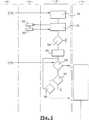
図3は、本発明による処理方法を図示する機能図である;
図4は、図3の図式の解釈モジュールの詳細図である;
図5は、図3の図式の別の解釈モジュールの詳細図である;
図6は、取手をロックしようとするときに開閉パネル取手内で実施される過程の概念図である;
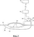
図7は、別の開閉パネル取手の概略図である;
図8は、図7の取手によって実施される方法を示す第一のグラフである;
図9は、同じ取手によって実施される方法を示す第二のグラフである。
【0075】
記載された実施態様において、取手1は把持するための中央部分2と二つの固定端とを含み、該固定端の一方3は旋回し、他方4は滑らかに動いてドアの開閉パネルを開くための取手操作を可能にする。
【0076】
中央部分2は取手を自分の方に引こうとする使用者の指のための空間を残す内部逃がし5を有している。
【0077】
内側の、この逃がし5に対応する領域で、取手は図に点線で境界を示した、近接検出区域6を有している。
【0078】
その滑らかに動く端4の外側に直角に、取手は同じく点線によって境界を示され、その一部が取手の開放端9に現れている容量性センサ8によって構成される接触検出区域7を有している。
【0079】
この接触区域7は使用者の指が押し当てられたのを検出するために備えられ、一方近接区域6は使用者が取手をつかむためにその後に指を通したのを検出する。
【0080】
図2に見るごとく、これら二つの区域の検出場6a、7aは寸法が異なり、近接検出区域6のスパンは接触検出区域7よりも大きい。
【0081】
取手はクローム仕上げにするためのメタリック塗料に覆われている(図示されていない)。
【0082】
この塗料は二つのセンサの可視性を妨げ、二つの検出区域6、7の少なくとも部分的な重なりを引き起こすか、そのおそれがある。
【0083】
くわえて、取手の人間工学上の構造は、前記取手をつかむか、それに接近する使用者の手が、二つの検出場6a、7aが重なっていなくても同時にその中にあるようなものとすることができる。
【0084】
このため、検出区域6、7を具体化する二つのセンサはときどき不正確な情報を提供する。
【0085】
本発明にかなった方法としては、図3に概略を示した処理手段10は、検出区域6、7と操作手段11の間に挿入され、該操作手段は、使用者によって要求された作用を決定し、実行するのに用いられる。
【0086】
図3に見るごとく、処理手段10は状態モジュール12、13と解釈モジュール14、15とを含む。
【0087】
それぞれの状態モジュール12、13は、各種の検出器16−19に接続されており、該検出器は、車両に配置され、車両の全体的状態を収集する機能を有する。
【0088】
例えば、検出器16は、車両の開閉パネルが施錠されたことを知らせる。検出器17はドアが開いていること、などを知らせる。
【0089】
このように、状態モジュール12、13は、使用者の要求に対応する作用を始動するのに適した判定条件に照らして車両の状態を総合的に決定することができる。
【0090】
検出区域6が肯定的な検出の判定条件、すなわち検出場6a内で検出された存在の判定条件だけによって操作手段11にかかわるという仮説に基づき、解釈モジュール14の役割は、操作手段11から見たとき、検出区域6が所定の条件が状態モジュールによって確認されたときに常に真の信号を提供するようにすることにある。
【0091】
このため、図4に示されたようなORゲート20が十分なものである。
【0092】
同様に、検出区域7が検出非在のための操作手段11にかかわる、すなわち操作手段が使用者が検出区域7a内に検出されないことだけを確認するという仮説に基づき、本発明にかなった方法としては、操作手段11に到達する信号が対応する所定の条件が確認されたときに常に偽になることが必要であり、これは検出区域が真の信号を発信したときにも当てはまる。
【0093】
このため、図5に示したごとく、所定の条件が満たされておらず、また、これらの条件が満たされたときには常に偽である、センサのものである信号を操作手段11に提供するために、状態検査モジュールの出力にNOゲート21を、またこの出力をセンサの信号に組み合わせるために、このNOゲートに続いてANDゲート22を配置する。
【0094】
操作手段の特異性に応じて解釈モジュールの他の構成も可能である。
【0095】
くわえて、操作手段は、その構成を変更することも可能であり、例えば、対応する所定の条件が満たされたときに検出区域の読取を無視するように制御分路を設置することによってなされる。
【0096】
本発明による処理方法は、例えば、外部接触検出区域7が車両の開閉パネルの手動施錠コマンドに対応し、内部近接検出区域6が鍵のアンロックを保証するために使用され、鍵の解放がドアの開放と警報の非作動を可能にするときに実施することができる。
【0097】
状態モジュールによって提供される状態である、車両の施錠状態において、施錠接触区域を読み取っても無駄である。したがって、この区域は本発明にかなった方法で抑制され、二つの検出信号のいずれか一つによって提供されたいっさいの検出は、内部センサから来るものと見なされる。
【0098】
逆に、ドアが開いているときは、内部近接検出区域を読み取っても無駄であり、取手の二つの検出信号のいずれか一つに由来するいっさいの信号は、すべての開閉パネルの手動施錠を操作する接触検出区域から必然的に由来するものと見なされる。
【0099】
状態モジュール12、13と解釈モジュール14、15は、本発明による処理方法が取手の内部で展開し、操作手段がもはや使用者によってなされる各種の考えられる作用の要求を判別する必要がないという意味で取手が車両の操作手段からロックとアンロックの明瞭な信号を出すユニットと見なされるように、特に取手に組み込まれる。
【0100】
取手の中で実施することができる処理方法の過程の連続の例を図6に示した。
【0101】
解釈モジュール14内で展開する第一の過程30の際に、検出区域6の作動に続く検出信号は解釈モジュールによって知覚される。
【0102】
次の過程31の際に、解釈モジュールは状態モジュール12に問い合わせ、後者は、過程32の際に、車両に設置された各種の検出器16−19に問い合わせ、次の過程33の際に、解釈モジュール14に総合化された状況情報を提供する。
【0103】
解釈モジュール14内で実行される次の過程34は、受信した状況情報のテストからなる。
【0104】
所定の条件が満たされないとき、方法は停止し、操作手段11には何の信号も送られない。
【0105】
反対に、状況条件が満たされたとき、解釈モジュール14は、過程35の際に、所定の時限の算出を始動する。
【0106】
次の過程36の際に、検出信号が相変わらず存在するかを知るために検出区域6のテストが再度実施される。
【0107】
否定の場合、使用者が取手を支える開閉パネルのロックを所望したと決定され、操作手段11にロック信号が送られる。
【0108】
肯定の場合、過程37に対応するテストによって方法が進行し続け、このテストの際に取手に存在するスイッチ(図1と2に示されていないスイッチ)が調べられる。所定の時間がすぎる前にスイッチが切り替わったことが分かったとき、方法は停止し、操作手段には何の信号も出力されない。
【0109】
反対に、スイッチが切り替わらなかったとき、方法は次の過程38に移行し、この間に、過程36のテストにループするために、あるいはループを出て操作手段11にロック信号を出力するために所定の時間が経過したかをテストする。
【0110】
すべての仮説において、操作手段は直接実行可能なロック信号を受信する。
【0111】
図7において、自動車の開閉パネル41の外側部分に取り付けられたドアの取手40は、光束43を送受するのに適した光近接センサ42を具備している。この光センサ42は、光束の遮断を検出したときに特徴的電気信号をハンドフリーアクセスシステムの認識装置44の方向に発信するために、それと電気的に接続されている。もっと具体的には、近接センサ42の光学発信器および受信器は取手内に取り付けられ、光束43は取手から開閉パネル41の方向に発射され、それによって取手の方向に反射されるため、車両使用者の手が取手の中に入れられたときに遮断され、それが認識装置44によって検出される。認識装置は周知のごとく車両の内部に設置され、車両の使用者によって担持された携帯識別ユニットと通信するのに適している。
【0112】
ドアの取手は例えば、操作されたときに取手が解放位置と呼ばれる静止位置からかみ合わせ位置に移動したときに位置を変える二位置スイッチ46を備え、それによって車両のドアの開放が可能になる。図7において、取手の解放位置はスイッチ46において47で示され、取手のかみ合わせ位置は48で示されている。このスイッチは認識装置44に接続され、スイッチの、ひいては取手の位置変化を表す信号をそれに提供する。取手のスイッチの代わりに開閉パネルが閉鎖位置から開放位置に、あるいはその逆に移動したときに位置を変える二位置(内部)開放ドア接触器を想定することもできるだろう。
【0113】
認識装置の方向にスイッチ46と近接センサ42によってそれぞれ発信された信号51と52を表す図8において、特に車両の運転者ドアであろう車両の開閉パネルの状態53の経時的な対応する変化が示されている。開始時、開閉パネルはアンロックされている。取手は解放状態にある:電気信号51はスイッチ46が位置47にあることを示す。持続時間54の間に光束43が遮断されたとき、信号52の変化1によってそれが検出され、認識装置44によってスイッチ46が位置47にとどまっていること(取手は解放されたまま)が確認され、スイッチ46の状態変化検出から起算された(2秒程度の)あらかじめ記録された持続時間△tの間に、信号51によってそれが示される。認識装置が持続時間△tの間にスイッチ46の状態変化を検出しないとき、持続時間△tの終わったときに車両の開閉パネルのロックを命じる。
【0114】
図3に示した本発明による方法の別の実施態様によれば、車両の開閉パネルのロックは光束が遮断されなくなり、信号52の変化によってそれが検出されるとすぐに命じられる。図8に図示された方法の展開に対して、図9のそれはハンドフリーアクセスシステムの反応性を高めるのに貢献する。すなわち、図9の場合、開閉パネルは△tよりも短い間でロックできる。しかしながら、この実施態様において、束がもはや遮断されていないことを検出した後にやはりスイッチ46を監視する必要がある。もっと具体的には、光束43が遮断されたことを検出してからごく短い間でスイッチ46の位置が変わった(例えば、取手がかみ合った)とき、スイッチの位置の変化を検出したらすぐに車両の開閉パネルのアンロックを命じる必要がある、なぜならそれは使用者が車両の開閉パネルの開放を所望している状況だからである。
【0115】
図8による方法の実施は、使用者が取手内で自分の手を移動したときのロックとアンロックの継起するタイプの不安定を回避するためのタイムコントロール△tを導入するために適合させることができる。
【0116】
光束43の遮断を検出したときに、認識装置44はさらに車両のロックを識別ユニット49の認証に条件付けるように、識別ユニット49の認証試行を実行することができるだろう。認証は、認識装置44によって認証された識別ユニット49が車両の外側にあるときにしか開閉パネルのロックコマンドが始動されないように識別ユニット49の場所の測定によって有利に補足することができる。
【0117】
開閉パネルのロックは従来光束43の遮断と、信号52の位置変化によって示される(操作された)取手40の位置変化の検出に基づいて行われる。
【0118】
したがって、本発明による方法は近接センサと二位置スイッチを備えたハンドフリーアクセスシステムを用いて車両の開閉パネルを自動的にロックおよびアンロックすることを可能にする。
【0119】
上述の例はいっさい制限的性格を持たない。いっさいの所望の変更を加えることができるがそれをもって本発明の範囲を逸脱することはできない。
【図面の簡単な説明】
【図1】 図1は、自動車のドアの取手の斜視図である。
【図2】 図2は、図1と同様な図でドアのそれぞれの検出区域の検出場を示している。
【図3】 図3は、本発明による処理方法を図示する機能図である。
【図4】 図4は、図3の図式の解釈モジュールの詳細図である。
【図5】 図5は、図3の図式の別の解釈モジュールの詳細図である。
【図6】 図6は、取手をロックしようとするときに開閉パネル取手内で実施される過程の概念図である。
【図7】 図7は、別の開閉パネル取手の概略図である。
【図8】 図8は、図7の取手によって実施される方法を示す第一のグラフである。
【図9】 図9は、同じ取手によって実施される方法を示す第二のグラフである。[0001]
[Technical field to which the invention belongs]
The present invention relates to a method for processing a detection signal originating from at least one detection zone arranged in a motor vehicle, a device for carrying out this method, a handle for an open / close panel and a motor vehicle equipped with such means.
[0002]
[Prior art and problems to be solved by the invention]
A vehicle equipped with at least one central locking system, on the one hand, for various sensors that collect information reflecting the user's behavior and, on the other hand, for starting various devices in response to the user's behavior Operation means for using these pieces of information is included.
[0003]
In modern vehicles, the use of capacitive or optical sensors tends to be common to achieve presence detection functions that do not use mechanical means.
[0004]
As such, capacitive or optical sensors are attached to the handle of the open / close panel, more specifically to the door.
[0005]
These sensors are not subject to any mechanical wear and are therefore advantageous in providing reliable information throughout their lifetime.
[0006]
For example, a capacitive sensor that is used to detect contact is called a contact sensor, or a sensor that is used to detect that a user's hand is approaching a certain surface is a proximity sensor. Call.
[0007]
The optical sensor detects the interruption of the light beam. This belongs to the category of proximity sensors.
[0008]
The existence of such sensors for the execution of various commands is certainly advantageous compared to mechanical sensors, as described above, however, all these sensors need to be managed at the same time, and There must be relatively complex electronic means in the vehicle suitable for resolving possible collisions between the sensors and the supply and installation costs of these sensors and associated electronic means. There are several problems associated with having to bear.
[0009]
The present invention is intended to propose a solution that optimizes the number of sensors used and simplifies the necessary electronic means in the vehicle.
[0010]
[Means for Solving the Problems]
The present invention is based on the so-called “hand”, in which a search for an identifier is first performed by various actions of the user to make it possible to know if the person whose action is detected is an authorized user of the vehicle. There are particularly advantageous applications for cars with "free" systems.
[0011]
An object of the present invention is to provide a detection signal processing method derived from at least one detection area arranged in an automobile, taking into account information information characteristic of the state of the vehicle after receiving the detection signal, According to the information information, the received signal is interpreted to provide an operation signal for the operation means belonging to the automobile.
[0012]
In the present invention, the operating means are: locking / unlocking the open / close panel, power fuse activation / deactivation, alarm activation / deactivation, engine start / stop command, and more generally any unit of any unit of the vehicle Means the entire device present in the vehicle to execute the / off command.
[0013]
According to the present invention, an instruction that can be directly executed by the operation means is output to the operation means in the form of an operation signal.
[0014]
In other words, the present invention is a first category of rules, which can be called identification rules, that allow the user to determine what the user's intention is when activating a detection area. Implements a distinction between the second category of rules, which may be referred to as arbitration rules, with respect to priority management between different intentions expressed by one or more users at the same time, which are inherently inconsistent or incompatible To do.
[0015]
According to the present invention, since the detection signal processing method is responsible for the application of the identification rule, if necessary, the operation means can be omitted only by guaranteeing the management of priority by the arbitration rule.
[0016]
In a particular embodiment, the status information relates to the locked state of the vehicle open / close panel.
[0017]
In other words, this method takes into account whether all of the open / close panels or at least some of them are locked or unlocked.
[0018]
In certain situations, knowing the situation information is not enough to interpret the detection correctly. This is because the detection always comes from the same sensor, but the user has two different locations on the vehicle (for example, only one sensor is actually included, There may be cases where the two borders are apparently separated by the boundary line. Therefore, the discrimination between the two operations must be performed by the processing method.
[0019]
Thus, according to a particular embodiment of the invention, when a detection signal is received, not only the status information but also time information related to the received detection signal, eg its duration or its reception and user The elapsed time between additional events triggered is also taken into account.
[0020]
The present invention contemplates various categories of commands as a result of interpretation of the detection signal. One of these commands is confirmation of the identity of the person whose behavior was detected, and this confirmation is particularly important as part of the “hands free” function.
[0021]
In order to trigger such an action, the status information is controlled to confirm that a predetermined condition, for example, all the open / close panels of the vehicle are locked. It can be assumed that the lock command will continue.
[0022]
In this case, the time information can be used to interpret the received signal as a lock or unlock command for only one open / close panel of the vehicle or for all open / close panels of the vehicle.
[0023]
These time information indicates that the long-time signal corresponds to, for example, unlocking of all the open / close panels, while the short-time signal corresponds to, for example, unlocking of the open / close panels related to the detection area. It can be a duration.
[0024]
In a variant, the time between the start of the received detection signal and the switch position change is selected as time information related to the received detection signal.
[0025]
For example, the switch can be tied to the open handle of the open / close panel, the switch changes position when the handle is operated or released, and all open / close panels are when the time reaches a predetermined duration. For example, while unlocked, the associated open / close panel is unlocked, for example, only when the time between the start of detection and the switch position change is less than a predetermined duration.
[0026]
Further, in the modified example, it is possible to adopt a rule that the open / close panel is unlocked when the time exceeds a predetermined duration.
[0027]
In a particular embodiment, the method of the present invention is implemented to automatically lock an automobile opening and closing panel by a hands-free access system including a recognition device for installation inside a vehicle and a portable identification unit; The recognition device is suitable for remote communication with an identification unit for authentication.
[0028]
This method is applied to a vehicle having a hands-free access system configured to allow a vehicle user to enter the vehicle without operating a key or a remote control.
[0029]
Such vehicles often include a proximity sensor coupled to the recognition device of the hands-free access system so that an authentication attempt is triggered when the proximity sensor detects the presence of a user. Thus, when the authentication attempt is successful, the recognition device initiates unlocking of one or more open / close panels of the vehicle.
[0030]
Conversely, in order to trigger the lock on the opening and closing panel of a vehicle equipped with a hands-free access system, the user typically activates a push button on the mobile identification unit, which in this case acts as a remote control, It is necessary to leave the communication area between the recognition device and the identification unit so that the recognition device inherently locks the vehicle.
[0031]
The disadvantage of these two lock modes of the vehicle is that the user can not trigger the lock of his vehicle in the vicinity to see if the lock was done properly without having to operate the mobile identification unit It is in.
[0032]
One object of the present invention is to eliminate this inconvenience by improving the ergonomics of the hands-free access system.
[0033]
DETAILED DESCRIPTION OF THE INVENTION
For this reason, in a particular embodiment, the method according to the invention consists in automatically locking the opening and closing panel of the vehicle by means of a hands-free access system comprising a recognition device and a portable identification unit for installation inside the vehicle, The recognition device is suitable for remotely communicating with the identification unit to authenticate it by providing a vehicle operating means lock or unlock signal to the vehicle operating means following authentication of the identification unit. .
[0034]
By this method, it becomes possible to lock the open / close panel of the vehicle without a remote control while remaining in the vicinity of the vehicle.
[0035]
The vehicle lock is realized, for example, by acting on the detection zone by hand, but without manipulating the door handle of the closed vehicle. In order to detect the release position or the engagement position of the handle, for example, it is only necessary to monitor the change in position of a two-position switch associated with the movement of the handle. Further, a change in the position of the (internal) release door contactor that detects the opening / closing position of the car door may be monitored. This method has the advantage that it can be implemented with parts already present in a hands-free access system that is configured to automatically activate the lock of the opening and closing panel of the vehicle.
[0036]
According to a preferred embodiment of the method according to the invention, the lock signal of the vehicle open / close panel is output as soon as the proximity sensor no longer provides a detection signal before the predetermined time has elapsed.
[0037]
In this way, the vehicle can be locked in a very short time.
[0038]
According to yet another particular embodiment of the method according to the invention, said predetermined time has a duration recorded in advance in the recognition device so as to avoid instability of operation associated with unlock criteria. .
[0039]
According to another particular embodiment of the method according to the invention, the locking of the vehicle is realized only by the user carrying the identification unit, since the recognition device does not output the lock signal of the open / close panel only when the identification unit authenticates Not.
[0040]
The present invention also relates to specific technical issues of the simultaneous management of multiple sensors that fall within the above-mentioned more general problem frame.
[0041]
That is, the door handle can be equipped with two capacitive sensors: one is directed inside the handle to act as a proximity sensor and the other is directed to the outside of the handle to act as a contact sensor. .
[0042]
The proximity sensor detects that the user has grabbed the handle, for example, passing his finger behind the handle to open the door.
[0043]
The contact sensor detects, for example, that the user presses his / her finger against the sensor in order to disable use of all the open / close panels of the vehicle.
[0044]
Therefore, each sensor corresponds to a specific function for the user.
[0045]
One problem with these capacitive sensors is that they block one or more sensors and suppress them, or, in the case of detection, the action of any sensor that reacts is not necessarily triggered by the user. Their good operating condition should not be in the vicinity of materials that can disrupt them, such as the electrically conductive material that places their sensing areas so that they are not related sensors. It is.
[0046]
In other words, the two sensors may operate unexpectedly, for example, erroneous information may be introduced into the detection signal operation means, and proximity detection may be erroneously taken as contact detection.
[0047]
Such confusion occurs especially when the sensor is covered with an electrically conductive paint.
[0048]
This is generally the case because, as is well known, there are metal particles introduced into the paint to achieve their painting by electrostatic attraction. This phenomenon is exacerbated when the paint is a metallized layer, in which case the metal pigment required for aesthetic expression is more sensitive to the sensor than the particles required to perform the electrostatic coating process. Interferes with the normal operation.
[0049]
The present invention therefore also contemplates a solution that makes it possible to overcome this problem due to the presence of materials that disrupt the normal operation of the sensor.
[0050]
Indeed, according to a particular embodiment of the invention, the received detection signal is interpreted as to be ignored when the situation information satisfies a predetermined condition.
[0051]
The method according to the invention thus makes it possible to intervene in signals provided by a plurality of sensors before the signals cause undesired actuation.
[0052]
Thus, in certain embodiments, detection signals derived from at least two independent detection zones, each suitable for providing a unique detection signal, can be processed.
[0053]
The present invention allows the inventors to deal with the reduced operation of the sensor without any degradation in terms of analysis of the detected signal, rather than trying to compensate for the sensor's shortcomings when the sensor is placed in an adverse environment. The originality of seeking a solution to make it.
[0054]
According to a particular embodiment of the invention, the detection zone is attached to the handle of the vehicle.
[0055]
According to an advantageous variant, the handle itself is attached to the opening and closing panel of the vehicle.
[0056]
As a method consistent with the present invention, the detection zone may be coated with a material that may disrupt normal operation. Such a material may be an electrically conductive material, such as a paint containing metal particles, and the detection area will be an area where fluctuations in the electric or electromagnetic field can be sensed.
[0057]
In accordance with the present invention, ignoring the signal in the detection area can consist of various implementations.
[0058]
First of all, ignoring the signal can suppress the means for reading the signal in the detection area.
[0059]
Signal ignorance can also be achieved by replacing the signal with a true Boolean constant signal, which is independent of the actual detection signaled by the sensor as soon as a predetermined condition is confirmed. However, it is considered that some detection has been made.
[0060]
Another possibility could be to replace the results of any monitoring performed on the detection signal, i.e. detection monitoring as well as monitoring without detection, with a true Boolean value. Regardless of the presence or absence, the signal from the considered sensor will no longer be considered.
[0061]
The present invention is also directed to an apparatus for carrying out the above-described method.
[0062]
Such a device comprises processing means including at least one state module suitable for taking into account situation information and at least one signal interpretation module, said interpretation module depending on the situation information and used directly by the operating means. Provide an activation signal that can be
[0063]
In a particular embodiment of the invention, the device further comprises duration measuring means and / or predetermined condition checking means for providing information relating to the received detection signal.
[0064]
In a particular embodiment, the interpretation module is arranged directly downstream of the sensor and consists of an OR gate that accepts the signal of the sensor on the one hand and the result of the condition check provided by the status module on the other hand.
[0065]
This embodiment performs only positive detection monitoring on the sensor, i.e. it is suitable for operating means to confirm that a detection has occurred, because these monitoring are of a predetermined condition when the condition is met. This is because the true value generated from the confirmation systematically becomes positive.
[0066]
In a variant suitable for operating means that only performs negative detection monitoring on the sensor, i.e. confirming that there is no detection, the OR gate is replaced by the NO gate at the output of the status monitoring module and the AND gate is This output is combined with the sensor signal.
[0067]
Finally, if the operating means uses the detection monitoring module to monitor positive and negative detection by the sensor, the interpretation module is not directly downstream of the detection area, but downstream of any detection monitoring module. It is preferably arranged by an OR gate that is directly arranged and combines the detection monitoring result with the confirmation result of the predetermined condition so that the monitoring result viewed from the operation means is always true when the predetermined condition is satisfied.
[0068]
In a particular embodiment of the invention, the detection zone is a part that is integrated into the handle of the vehicle, the latter being advantageously attached to the opening and closing panel of the vehicle.
[0069]
The present invention is also directed to an automotive open / close panel handle having a processing device as described above, which on the one hand provides an activation signal which can be used directly by operating means external to the handle and on the other hand an operating means. And
[0070]
In certain embodiments, the detection area of the handle senses fluctuations in the electric or electromagnetic field, or blockage of the light flux.
[0071]
The detection area is advantageously arranged on the handle so that when the hand is put into the handle, the surrounding electric or electromagnetic field is disturbed or the luminous flux is interrupted.
[0072]
Finally, the present invention is directed to a motor vehicle including at least one open / close panel, at least one detection zone, and a processing device as described above.
[0073]
In certain embodiments, the open / close panel includes a handle incorporating a processing device.
[0074]
【Example】
For the purpose of facilitating the understanding of the present invention, non-limiting examples will now be described with reference to the accompanying drawings.
FIG. 1 is a perspective view of a handle of a car door;
FIG. 2 is a view similar to FIG. 1 showing the detection field of each detection area of the door;
FIG. 3 is a functional diagram illustrating the processing method according to the invention;
4 is a detailed view of the schematic interpretation module of FIG. 3;
FIG. 5 is a detailed view of another interpretation module of the diagram of FIG. 3;
FIG. 6 is a conceptual diagram of the process performed in the opening / closing panel handle when trying to lock the handle;
FIG. 7 is a schematic view of another open / close panel handle;
FIG. 8 is a first graph illustrating the method performed by the handle of FIG. 7;
FIG. 9 is a second graph showing a method performed by the same handle.
[0075]
In the described embodiment, the handle 1 comprises a central part 2 for gripping and two fixed ends, one of the fixed ends 3 pivots and the other 4 moves smoothly to open the door opening and closing panel Enables handle operation.
[0076]
The central part 2 has an internal relief 5 that leaves space for the user's finger to pull the handle towards him.
[0077]
In the area corresponding to this relief 5 on the inside, the handle has a
[0078]
At right angles to its smoothly moving end 4, the handle also has a touch detection area 7 constituted by a capacitive sensor 8 which is bounded by a dotted line, part of which appears at the
[0079]
This contact area 7 is provided to detect that the user's finger has been pressed, while the
[0080]
As seen in FIG. 2, the
[0081]
The handle is covered with a metallic paint for a chrome finish (not shown).
[0082]
This paint interferes with the visibility of the two sensors and may cause or possibly cause at least partial overlap of the two
[0083]
In addition, the ergonomic structure of the handle is such that the user's hand grabbing the handle or approaching it will be in it at the same time even if the two
[0084]
For this reason, the two sensors that embody the
[0085]
As a method according to the invention, the processing means 10 outlined in FIG. 3 is inserted between the
[0086]
As seen in FIG. 3, the processing means 10 includes
[0087]
Each
[0088]
For example, the
[0089]
Thus, the
[0090]
The role of the
[0091]
For this reason, the
[0092]
Similarly, the method according to the present invention is based on the hypothesis that the detection zone 7 involves the operating means 11 for the absence of detection, ie that the operating means only confirms that the user is not detected in the
[0093]
For this reason, as shown in FIG. 5, in order to provide the operating means 11 with a signal that belongs to the sensor that does not satisfy the predetermined conditions and is always false when these conditions are satisfied. A NO
[0094]
Other configurations of the interpretation module are possible depending on the specificity of the operating means.
[0095]
In addition, the operation means can be changed in its configuration, for example, by installing a control shunt so that reading of the detection area is ignored when a corresponding predetermined condition is met. .
[0096]
The processing method according to the invention is used, for example, in which the external contact detection area 7 corresponds to a manual locking command on the open / close panel of the vehicle, the internal
[0097]
It is useless to read the locking contact area in the locked state of the vehicle, which is the state provided by the state module. Thus, this area is suppressed in a manner consistent with the present invention, and any detection provided by either one of the two detection signals is considered to come from an internal sensor.
[0098]
Conversely, when the door is open, it is useless to read the internal proximity detection area, and any signal derived from one of the two detection signals of the handle must be manually locked on all open / close panels. It is considered to be necessarily derived from the touch detection area to be operated.
[0099]
The
[0100]
An example of a sequence of processing methods that can be carried out in the handle is shown in FIG.
[0101]
During the
[0102]
During the
[0103]
The
[0104]
When the predetermined condition is not met, the method stops and no signal is sent to the operating means 11.
[0105]
Conversely, when the situation condition is met,
[0106]
During the
[0107]
In the negative case, it is determined that the user desires to lock the open / close panel that supports the handle, and a lock signal is sent to the operation means 11.
[0108]
If affirmative, the method continues with the test corresponding to step 37, and the switches present in the handle (switches not shown in FIGS. 1 and 2) are examined during this test. If it is found that the switch has been switched before the predetermined time has passed, the method stops and no signal is output to the operating means.
[0109]
On the other hand, when the switch has not been switched, the method moves to the
[0110]
In all hypotheses, the operating means receives a directly executable lock signal.
[0111]
In FIG. 7, a
[0112]
The door handle includes, for example, a two-
[0113]
In FIG. 8, which represents the
[0114]
According to another embodiment of the method according to the invention shown in FIG. 3, the locking of the vehicle opening and closing panel is commanded as soon as the light beam is not blocked and is detected by a change in the
[0115]
The implementation of the method according to FIG. 8 is adapted to introduce a time control Δt to avoid the type of instability of locking and unlocking when the user moves his hand within the handle. Can do.
[0116]
When detecting the blockage of the
[0117]
The opening / closing panel is locked based on the detection of the position change of the
[0118]
The method according to the invention thus makes it possible to automatically lock and unlock the opening and closing panel of a vehicle using a hands-free access system with a proximity sensor and a two-position switch.
[0119]
The above example has no restrictive character. Any desired changes can be made, but without departing from the scope of the present invention.
[Brief description of the drawings]
FIG. 1 is a perspective view of a handle of an automobile door.
FIG. 2 is a view similar to FIG. 1 showing the detection field of each detection area of the door.
FIG. 3 is a functional diagram illustrating a processing method according to the present invention.
FIG. 4 is a detailed view of the graphical interpretation module of FIG. 3;
FIG. 5 is a detailed view of another interpretation module of the diagram of FIG. 3;
FIG. 6 is a conceptual diagram of a process performed in the opening / closing panel handle when the handle is to be locked.
FIG. 7 is a schematic view of another opening / closing panel handle.
FIG. 8 is a first graph showing the method performed by the handle of FIG. 7;
FIG. 9 is a second graph showing a method performed by the same handle.
Claims (24)
Translated fromJapanese状況情報が所定の条件を満たすときに信号が無視されるべきものと解釈され、
状況情報を考慮するのに適した少なくとも一つの状態モジュール(12、13)があり、少なくとも一つの信号解釈モジュール(14、15)が、状況情報に依存し、操作手段によって直接使用することのできる作動信号を提供し、
状況情報は、車両の開閉パネル(41)の施錠状態に関するものであり、
検出区域(6、7、42)とともに自動車の開閉パネル取手(1)の一部を構成する処理装置の一部を、状態モジュール(12、13)と信号解釈モジュール(14、15)が構成することを特徴とする、検出信号処理方法。These statuses are derived from at least one detection zone (6, 7, 42) located in the car and after receiving the detection signal (52), taking into account the situation information characteristic of the state of the vehicle. Adetection signal processing method comprising interpreting a received signal according to information and providing an operation signal for an operating means belonging to an automobile;
It is interpreted that the signal should be ignored when the status information meets the predetermined conditions ,
There is at least one state module (12, 13) suitable for considering the situation information, and at least one signal interpretation module (14, 15) depends on the situation information and can be used directly by the operating means. Provide an activation signal,
The situation information relates to the locked state of the open / close panel (41) of the vehicle,
A state module (12, 13) and a signal interpretation module (14, 15) constitute a part of the processing device that constitutes a part of the open / close panel handle (1) of the automobile together with the detection area (6, 7, 42). A detection signal processing method characterized by the above.
該処理装置は、自動車の開閉パネル(41)のロックされた状態に関する状況情報を考慮するのに適した少なくとも一つの状態モジュール(12、13)と、該状況情報に依存し、操作手段によって直接使用することのできる作動信号を提供する、少なくとも一つの信号解釈モジュール(14、15)で構成されることを特徴とする、自動車の開閉パネル取手。A car door panel handle having at least one detection zone (6, 7, 42) and a processing device (10) for performing the method according to any one of claims 1 to 16,
The processorincludes at least one state module adapted to consider the status informationabout the locked state of the vehicle close panel (41) (12,13), depending onthe status information, directly by the operating meansOpening and closing panel handle of anautomobile, characterizedin that itcomprises at least one signal interpretation module (14, 15) that provides an operational signal that can be used.
Applications Claiming Priority (5)
| Application Number | Priority Date | Filing Date | Title |
|---|---|---|---|
| FR0011299AFR2813630B1 (en) | 2000-09-05 | 2000-09-05 | METHOD FOR AUTOMATICALLY LOCKING A VEHICLE OPENING ELEMENT WITH A HANDS-FREE ACCESS SYSTEM AND AN APPROACH SENSOR |
| FR00/11299 | 2000-09-05 | ||
| FR01/08901 | 2001-07-04 | ||
| FR0108901AFR2827064B1 (en) | 2001-07-04 | 2001-07-04 | METHOD FOR PROCESSING DETECTION SIGNALS FROM AT LEAST ONE DETECTION AREA OF A MOTOR VEHICLE, DEVICE FOR CARRYING OUT THIS METHOD AND HANDLE FOR A MOTOR VEHICLE |
| PCT/EP2001/010167WO2002021455A1 (en) | 2000-09-05 | 2001-09-04 | Method for processing detection signals for a motor vehicle |
Publications (2)
| Publication Number | Publication Date |
|---|---|
| JP2004520497A JP2004520497A (en) | 2004-07-08 |
| JP4783543B2true JP4783543B2 (en) | 2011-09-28 |
Family
ID=26212599
Family Applications (1)
| Application Number | Title | Priority Date | Filing Date |
|---|---|---|---|
| JP2002525590AExpired - Fee RelatedJP4783543B2 (en) | 2000-09-05 | 2001-09-04 | Detection signal processing method for automobile |
Country Status (4)
| Country | Link |
|---|---|
| EP (1) | EP1328907B1 (en) |
| JP (1) | JP4783543B2 (en) |
| DE (1) | DE60142440D1 (en) |
| WO (1) | WO2002021455A1 (en) |
Families Citing this family (10)
| Publication number | Priority date | Publication date | Assignee | Title |
|---|---|---|---|---|
| JP4003453B2 (en) | 2001-12-26 | 2007-11-07 | アイシン精機株式会社 | Human body detection device |
| DE10300572A1 (en)* | 2003-01-10 | 2004-07-22 | Daimlerchrysler Ag | Door handle and locking system for a vehicle door |
| JP2004232300A (en)* | 2003-01-29 | 2004-08-19 | Aisin Seiki Co Ltd | Outside handle device |
| FR2853346B1 (en)* | 2003-04-01 | 2005-06-24 | Peugeot Citroen Automobiles Sa | METHOD FOR LIMITING A REBOUND EFFECT OF A DEVICE FOR LOCKING AND UNLOCKING A LOCK IN A DOOR OF A MOTOR VEHICLE |
| US7026861B2 (en) | 2003-04-22 | 2006-04-11 | Touchsensor Technologies Llc | Electronic door latch system with water rejection filtering |
| DE10341402A1 (en)* | 2003-09-05 | 2005-04-07 | Brose Schließsysteme GmbH & Co.KG | Motor vehicle door locking system and inside door handle |
| DE102004019571B4 (en)* | 2004-04-22 | 2006-02-23 | Huf Hülsbeck & Fürst Gmbh & Co. Kg | Device for actuating an electrical or mechanical closing device on a door and / or a flap of a vehicle |
| DE202004017179U1 (en)* | 2004-11-03 | 2006-03-16 | Brose Schließsysteme GmbH & Co.KG | Vehicle locking system comprises a door handle arrangement with the exchangeable component of a control system and an assigned interface |
| US9022436B2 (en) | 2011-05-05 | 2015-05-05 | GM Global Technology Operations LLC | Actuator arrangement for a vehicle door latch |
| US10704315B2 (en)* | 2018-06-12 | 2020-07-07 | GM Global Technology Operations LLC | Presenting door open sensors |
Citations (2)
| Publication number | Priority date | Publication date | Assignee | Title |
|---|---|---|---|---|
| US5973611A (en)* | 1995-03-27 | 1999-10-26 | Ut Automotive Dearborn, Inc. | Hands-free remote entry system |
| JP2000017916A (en)* | 1998-07-06 | 2000-01-18 | Aisin Seiki Co Ltd | Remote control device |
Family Cites Families (4)
| Publication number | Priority date | Publication date | Assignee | Title |
|---|---|---|---|---|
| DE19617038C2 (en)* | 1996-04-27 | 2000-11-30 | Huf Huelsbeck & Fuerst Gmbh | Locking system, in particular for motor vehicles |
| JPH1079986A (en)* | 1996-09-04 | 1998-03-24 | Tokai Rika Co Ltd | Load controller for vehicle |
| DE19710476A1 (en)* | 1997-03-13 | 1998-09-17 | Siemens Ag | Selective and global opening of motor vehicles by remote control |
| US6768413B1 (en)* | 1997-10-14 | 2004-07-27 | Huf Hülsbeck & Fürst Gmbh & Co. Kg | Closing device, in particular for motor vehicles |
- 2001
- 2001-09-04JPJP2002525590Apatent/JP4783543B2/ennot_activeExpired - Fee Related
- 2001-09-04WOPCT/EP2001/010167patent/WO2002021455A1/enactiveApplication Filing
- 2001-09-04EPEP01969688Apatent/EP1328907B1/ennot_activeExpired - Lifetime
- 2001-09-04DEDE60142440Tpatent/DE60142440D1/ennot_activeExpired - Lifetime
Patent Citations (2)
| Publication number | Priority date | Publication date | Assignee | Title |
|---|---|---|---|---|
| US5973611A (en)* | 1995-03-27 | 1999-10-26 | Ut Automotive Dearborn, Inc. | Hands-free remote entry system |
| JP2000017916A (en)* | 1998-07-06 | 2000-01-18 | Aisin Seiki Co Ltd | Remote control device |
Also Published As
| Publication number | Publication date |
|---|---|
| DE60142440D1 (en) | 2010-08-05 |
| WO2002021455A9 (en) | 2003-03-20 |
| JP2004520497A (en) | 2004-07-08 |
| EP1328907A1 (en) | 2003-07-23 |
| WO2002021455A1 (en) | 2002-03-14 |
| EP1328907B1 (en) | 2010-06-23 |
Similar Documents
| Publication | Publication Date | Title |
|---|---|---|
| US7233080B2 (en) | Method for processing detection signals for a motor vehicle | |
| KR100850599B1 (en) | Vehicle control system and method for controlling a device provided in a vehicle | |
| US8054158B2 (en) | On-vehicle equipment control system | |
| US7868735B2 (en) | Vehicle door control system | |
| JP6074037B2 (en) | Dual function power door | |
| JP4488050B2 (en) | Smart entry system | |
| KR101851837B1 (en) | Closing device for a vehicle, and method for operating a closing device | |
| KR100766189B1 (en) | Vehicle door control system and method | |
| US7091836B2 (en) | Motor vehicle door locking system and door handle | |
| JP4783543B2 (en) | Detection signal processing method for automobile | |
| KR100885363B1 (en) | Vehicle door controls | |
| US20140136024A1 (en) | Error avoidance in the gesture-controlled opening of a motor vehicle door and trunk | |
| CN111663870A (en) | Concealed door handle controller | |
| US7315237B2 (en) | Automotive antitheft system | |
| JP2016527419A (en) | Access control system for automobile | |
| WO2002025040A1 (en) | Proximity activated entry system | |
| CN116892345A (en) | Assembly of a vehicle with an operating element arranged on a door | |
| CN112352085A (en) | Method for unlocking a hood of a vehicle | |
| US20040160126A1 (en) | Vehicle door operation system | |
| KR20120032145A (en) | Method and system for controlling door lock of vehicle | |
| JP5083412B2 (en) | Vehicle control apparatus and method | |
| JP4599534B2 (en) | Vehicle access system and control method thereof | |
| KR101983665B1 (en) | Automatic authentication control apparatus of smart key interlocking touch panel and method thereof | |
| JP4839701B2 (en) | VEHICLE LOCK CONTROL DEVICE AND LOCK CONTROL METHOD | |
| JP2008121196A (en) | Opening-closing device of vehicle door |
Legal Events
| Date | Code | Title | Description |
|---|---|---|---|
| A621 | Written request for application examination | Free format text:JAPANESE INTERMEDIATE CODE: A621 Effective date:20080617 | |
| A131 | Notification of reasons for refusal | Free format text:JAPANESE INTERMEDIATE CODE: A131 Effective date:20101026 | |
| A601 | Written request for extension of time | Free format text:JAPANESE INTERMEDIATE CODE: A601 Effective date:20110124 | |
| A602 | Written permission of extension of time | Free format text:JAPANESE INTERMEDIATE CODE: A602 Effective date:20110131 | |
| A521 | Request for written amendment filed | Free format text:JAPANESE INTERMEDIATE CODE: A523 Effective date:20110425 | |
| TRDD | Decision of grant or rejection written | ||
| A01 | Written decision to grant a patent or to grant a registration (utility model) | Free format text:JAPANESE INTERMEDIATE CODE: A01 Effective date:20110531 | |
| A01 | Written decision to grant a patent or to grant a registration (utility model) | Free format text:JAPANESE INTERMEDIATE CODE: A01 | |
| A61 | First payment of annual fees (during grant procedure) | Free format text:JAPANESE INTERMEDIATE CODE: A61 Effective date:20110711 | |
| FPAY | Renewal fee payment (event date is renewal date of database) | Free format text:PAYMENT UNTIL: 20140715 Year of fee payment:3 | |
| R150 | Certificate of patent or registration of utility model | Free format text:JAPANESE INTERMEDIATE CODE: R150 Ref document number:4783543 Country of ref document:JP Free format text:JAPANESE INTERMEDIATE CODE: R150 | |
| R250 | Receipt of annual fees | Free format text:JAPANESE INTERMEDIATE CODE: R250 | |
| R250 | Receipt of annual fees | Free format text:JAPANESE INTERMEDIATE CODE: R250 | |
| R250 | Receipt of annual fees | Free format text:JAPANESE INTERMEDIATE CODE: R250 | |
| R250 | Receipt of annual fees | Free format text:JAPANESE INTERMEDIATE CODE: R250 | |
| R250 | Receipt of annual fees | Free format text:JAPANESE INTERMEDIATE CODE: R250 | |
| LAPS | Cancellation because of no payment of annual fees |