JP4783014B2 - Ultrasound catheter for breaking vascular occlusion - Google Patents
Ultrasound catheter for breaking vascular occlusionDownload PDFInfo
- Publication number
- JP4783014B2 JP4783014B2JP2004531258AJP2004531258AJP4783014B2JP 4783014 B2JP4783014 B2JP 4783014B2JP 2004531258 AJP2004531258 AJP 2004531258AJP 2004531258 AJP2004531258 AJP 2004531258AJP 4783014 B2JP4783014 B2JP 4783014B2
- Authority
- JP
- Japan
- Prior art keywords
- catheter
- catheter body
- ultrasonic
- distal
- transmission member
- Prior art date
- Legal status (The legal status is an assumption and is not a legal conclusion. Google has not performed a legal analysis and makes no representation as to the accuracy of the status listed.)
- Expired - Fee Related
Links
- 238000002604ultrasonographyMethods0.000titleclaimsdescription78
- 206010053648Vascular occlusionDiseases0.000titledescription14
- 208000021331vascular occlusion diseaseDiseases0.000titledescription6
- 230000005540biological transmissionEffects0.000claimsdescription108
- 239000012530fluidSubstances0.000claimsdescription24
- 239000000853adhesiveSubstances0.000claimsdescription14
- 230000001070adhesive effectEffects0.000claimsdescription14
- 229920000642polymerPolymers0.000claimsdescription9
- 210000004204blood vesselAnatomy0.000claimsdescription8
- 239000000463materialSubstances0.000description21
- 238000000034methodMethods0.000description12
- 229910045601alloyInorganic materials0.000description11
- 239000000956alloySubstances0.000description11
- 239000011248coating agentSubstances0.000description11
- 238000000576coating methodMethods0.000description11
- 230000000295complement effectEffects0.000description7
- 230000002745absorbentEffects0.000description6
- 239000002250absorbentSubstances0.000description6
- 238000007667floatingMethods0.000description6
- 229910052751metalInorganic materials0.000description6
- 239000002184metalSubstances0.000description6
- 239000002826coolantSubstances0.000description5
- 230000008878couplingEffects0.000description5
- 238000010168coupling processMethods0.000description5
- 238000005859coupling reactionMethods0.000description5
- 229910000734martensiteInorganic materials0.000description5
- -1polytetrafluoroethylenePolymers0.000description5
- 229910001285shape-memory alloyInorganic materials0.000description5
- 238000002679ablationMethods0.000description4
- 239000006096absorbing agentSubstances0.000description4
- 238000002347injectionMethods0.000description4
- 239000007924injectionSubstances0.000description4
- 239000004033plasticSubstances0.000description4
- 229920003023plasticPolymers0.000description4
- 230000005855radiationEffects0.000description4
- 230000007704transitionEffects0.000description4
- 210000005166vasculatureAnatomy0.000description4
- 229910001566austeniteInorganic materials0.000description3
- 239000012809cooling fluidSubstances0.000description3
- 230000006872improvementEffects0.000description3
- 229920001343polytetrafluoroethylenePolymers0.000description3
- 239000004810polytetrafluoroethyleneSubstances0.000description3
- 239000004698PolyethyleneSubstances0.000description2
- RTAQQCXQSZGOHL-UHFFFAOYSA-NTitaniumChemical compound[Ti]RTAQQCXQSZGOHL-UHFFFAOYSA-N0.000description2
- 238000007792additionMethods0.000description2
- 238000001816coolingMethods0.000description2
- 210000004351coronary vesselAnatomy0.000description2
- 230000006378damageEffects0.000description2
- 238000012217deletionMethods0.000description2
- 230000037430deletionEffects0.000description2
- 238000001802infusionMethods0.000description2
- 230000002262irrigationEffects0.000description2
- 238000003973irrigationMethods0.000description2
- 230000007246mechanismEffects0.000description2
- 239000007769metal materialSubstances0.000description2
- 238000012986modificationMethods0.000description2
- 230000004048modificationEffects0.000description2
- 229920000573polyethylenePolymers0.000description2
- 230000002028prematureEffects0.000description2
- 239000000243solutionSubstances0.000description2
- 239000010936titaniumSubstances0.000description2
- 238000012546transferMethods0.000description2
- 229910000838Al alloyInorganic materials0.000description1
- 206010003210ArteriosclerosisDiseases0.000description1
- 208000037260Atherosclerotic PlaqueDiseases0.000description1
- 235000003801Castanea crenataNutrition0.000description1
- 244000209117Castanea crenataSpecies0.000description1
- 235000008733Citrus aurantifoliaNutrition0.000description1
- 229920001651CyanoacrylatePolymers0.000description1
- 208000005189EmbolismDiseases0.000description1
- 241001645095ParisisSpecies0.000description1
- FAPWRFPIFSIZLT-UHFFFAOYSA-MSodium chlorideChemical compound[Na+].[Cl-]FAPWRFPIFSIZLT-UHFFFAOYSA-M0.000description1
- 229920006362Teflon®Polymers0.000description1
- 208000001435ThromboembolismDiseases0.000description1
- 229910001069Ti alloyInorganic materials0.000description1
- 235000011941Tilia x europaeaNutrition0.000description1
- 239000004676acrylonitrile butadiene styreneSubstances0.000description1
- 210000003484anatomyAnatomy0.000description1
- 210000002376aorta thoracicAnatomy0.000description1
- 238000013459approachMethods0.000description1
- 230000006399behaviorEffects0.000description1
- 230000009286beneficial effectEffects0.000description1
- 230000008901benefitEffects0.000description1
- 229910052797bismuthInorganic materials0.000description1
- JCXGWMGPZLAOME-UHFFFAOYSA-Nbismuth atomChemical compound[Bi]JCXGWMGPZLAOME-UHFFFAOYSA-N0.000description1
- 239000000919ceramicSubstances0.000description1
- 238000004891communicationMethods0.000description1
- 239000000110cooling liquidSubstances0.000description1
- NLCKLZIHJQEMCU-UHFFFAOYSA-Ncyano prop-2-enoateChemical classC=CC(=O)OC#NNLCKLZIHJQEMCU-UHFFFAOYSA-N0.000description1
- 230000001419dependent effectEffects0.000description1
- 208000037265diseases, disorders, signs and symptomsDiseases0.000description1
- 239000003814drugSubstances0.000description1
- 229940079593drugDrugs0.000description1
- 230000002526effect on cardiovascular systemEffects0.000description1
- 210000001105femoral arteryAnatomy0.000description1
- 239000000945fillerSubstances0.000description1
- 239000011888foilSubstances0.000description1
- 238000003780insertionMethods0.000description1
- 230000037431insertionEffects0.000description1
- 239000004571limeSubstances0.000description1
- 239000007788liquidSubstances0.000description1
- 239000000203mixtureSubstances0.000description1
- 239000002991molded plasticSubstances0.000description1
- 238000013021overheatingMethods0.000description1
- 210000005259peripheral bloodAnatomy0.000description1
- 239000011886peripheral bloodSubstances0.000description1
- 230000000704physical effectEffects0.000description1
- 239000002861polymer materialSubstances0.000description1
- 229920002635polyurethanePolymers0.000description1
- 239000004814polyurethaneSubstances0.000description1
- 239000011148porous materialSubstances0.000description1
- 230000000452restraining effectEffects0.000description1
- 239000011780sodium chlorideSubstances0.000description1
- 239000000126substanceSubstances0.000description1
- 230000001629suppressionEffects0.000description1
- 229910052719titaniumInorganic materials0.000description1
- 210000003462veinAnatomy0.000description1
- XLYOFNOQVPJJNP-UHFFFAOYSA-NwaterSubstancesOXLYOFNOQVPJJNP-UHFFFAOYSA-N0.000description1
- 238000004804windingMethods0.000description1
Images


Classifications
- A—HUMAN NECESSITIES
- A61—MEDICAL OR VETERINARY SCIENCE; HYGIENE
- A61B—DIAGNOSIS; SURGERY; IDENTIFICATION
- A61B17/00—Surgical instruments, devices or methods
- A61B17/22—Implements for squeezing-off ulcers or the like on inner organs of the body; Implements for scraping-out cavities of body organs, e.g. bones; for invasive removal or destruction of calculus using mechanical vibrations; for removing obstructions in blood vessels, not otherwise provided for
- A61B17/22004—Implements for squeezing-off ulcers or the like on inner organs of the body; Implements for scraping-out cavities of body organs, e.g. bones; for invasive removal or destruction of calculus using mechanical vibrations; for removing obstructions in blood vessels, not otherwise provided for using mechanical vibrations, e.g. ultrasonic shock waves
- A61B17/22012—Implements for squeezing-off ulcers or the like on inner organs of the body; Implements for scraping-out cavities of body organs, e.g. bones; for invasive removal or destruction of calculus using mechanical vibrations; for removing obstructions in blood vessels, not otherwise provided for using mechanical vibrations, e.g. ultrasonic shock waves in direct contact with, or very close to, the obstruction or concrement
- A—HUMAN NECESSITIES
- A61—MEDICAL OR VETERINARY SCIENCE; HYGIENE
- A61M—DEVICES FOR INTRODUCING MEDIA INTO, OR ONTO, THE BODY; DEVICES FOR TRANSDUCING BODY MEDIA OR FOR TAKING MEDIA FROM THE BODY; DEVICES FOR PRODUCING OR ENDING SLEEP OR STUPOR
- A61M37/00—Other apparatus for introducing media into the body; Percutany, i.e. introducing medicines into the body by diffusion through the skin
- A61M37/0092—Other apparatus for introducing media into the body; Percutany, i.e. introducing medicines into the body by diffusion through the skin using ultrasonic, sonic or infrasonic vibrations, e.g. phonophoresis
- A—HUMAN NECESSITIES
- A61—MEDICAL OR VETERINARY SCIENCE; HYGIENE
- A61B—DIAGNOSIS; SURGERY; IDENTIFICATION
- A61B17/00—Surgical instruments, devices or methods
- A61B2017/00477—Coupling
- A—HUMAN NECESSITIES
- A61—MEDICAL OR VETERINARY SCIENCE; HYGIENE
- A61B—DIAGNOSIS; SURGERY; IDENTIFICATION
- A61B17/00—Surgical instruments, devices or methods
- A61B17/22—Implements for squeezing-off ulcers or the like on inner organs of the body; Implements for scraping-out cavities of body organs, e.g. bones; for invasive removal or destruction of calculus using mechanical vibrations; for removing obstructions in blood vessels, not otherwise provided for
- A61B17/22004—Implements for squeezing-off ulcers or the like on inner organs of the body; Implements for scraping-out cavities of body organs, e.g. bones; for invasive removal or destruction of calculus using mechanical vibrations; for removing obstructions in blood vessels, not otherwise provided for using mechanical vibrations, e.g. ultrasonic shock waves
- A61B17/22012—Implements for squeezing-off ulcers or the like on inner organs of the body; Implements for scraping-out cavities of body organs, e.g. bones; for invasive removal or destruction of calculus using mechanical vibrations; for removing obstructions in blood vessels, not otherwise provided for using mechanical vibrations, e.g. ultrasonic shock waves in direct contact with, or very close to, the obstruction or concrement
- A61B2017/22014—Implements for squeezing-off ulcers or the like on inner organs of the body; Implements for scraping-out cavities of body organs, e.g. bones; for invasive removal or destruction of calculus using mechanical vibrations; for removing obstructions in blood vessels, not otherwise provided for using mechanical vibrations, e.g. ultrasonic shock waves in direct contact with, or very close to, the obstruction or concrement the ultrasound transducer being outside patient's body; with an ultrasound transmission member; with a wave guide; with a vibrated guide wire
- A61B2017/22015—Implements for squeezing-off ulcers or the like on inner organs of the body; Implements for scraping-out cavities of body organs, e.g. bones; for invasive removal or destruction of calculus using mechanical vibrations; for removing obstructions in blood vessels, not otherwise provided for using mechanical vibrations, e.g. ultrasonic shock waves in direct contact with, or very close to, the obstruction or concrement the ultrasound transducer being outside patient's body; with an ultrasound transmission member; with a wave guide; with a vibrated guide wire with details of the transmission member
- A61B2017/22018—Implements for squeezing-off ulcers or the like on inner organs of the body; Implements for scraping-out cavities of body organs, e.g. bones; for invasive removal or destruction of calculus using mechanical vibrations; for removing obstructions in blood vessels, not otherwise provided for using mechanical vibrations, e.g. ultrasonic shock waves in direct contact with, or very close to, the obstruction or concrement the ultrasound transducer being outside patient's body; with an ultrasound transmission member; with a wave guide; with a vibrated guide wire with details of the transmission member segmented along its length
- A—HUMAN NECESSITIES
- A61—MEDICAL OR VETERINARY SCIENCE; HYGIENE
- A61B—DIAGNOSIS; SURGERY; IDENTIFICATION
- A61B17/00—Surgical instruments, devices or methods
- A61B17/22—Implements for squeezing-off ulcers or the like on inner organs of the body; Implements for scraping-out cavities of body organs, e.g. bones; for invasive removal or destruction of calculus using mechanical vibrations; for removing obstructions in blood vessels, not otherwise provided for
- A61B2017/22038—Implements for squeezing-off ulcers or the like on inner organs of the body; Implements for scraping-out cavities of body organs, e.g. bones; for invasive removal or destruction of calculus using mechanical vibrations; for removing obstructions in blood vessels, not otherwise provided for with a guide wire
- A—HUMAN NECESSITIES
- A61—MEDICAL OR VETERINARY SCIENCE; HYGIENE
- A61B—DIAGNOSIS; SURGERY; IDENTIFICATION
- A61B17/00—Surgical instruments, devices or methods
- A61B17/32—Surgical cutting instruments
- A61B17/320068—Surgical cutting instruments using mechanical vibrations, e.g. ultrasonic
- A61B2017/320072—Working tips with special features, e.g. extending parts
- A61B2017/320073—Working tips with special features, e.g. extending parts probe
- A—HUMAN NECESSITIES
- A61—MEDICAL OR VETERINARY SCIENCE; HYGIENE
- A61B—DIAGNOSIS; SURGERY; IDENTIFICATION
- A61B17/00—Surgical instruments, devices or methods
- A61B17/32—Surgical cutting instruments
- A61B17/320068—Surgical cutting instruments using mechanical vibrations, e.g. ultrasonic
- A61B2017/320084—Irrigation sleeves
Landscapes
- Health & Medical Sciences (AREA)
- Life Sciences & Earth Sciences (AREA)
- Engineering & Computer Science (AREA)
- Surgery (AREA)
- Veterinary Medicine (AREA)
- General Health & Medical Sciences (AREA)
- Public Health (AREA)
- Animal Behavior & Ethology (AREA)
- Biomedical Technology (AREA)
- Heart & Thoracic Surgery (AREA)
- Medical Informatics (AREA)
- Molecular Biology (AREA)
- Orthopedic Medicine & Surgery (AREA)
- Nuclear Medicine, Radiotherapy & Molecular Imaging (AREA)
- Vascular Medicine (AREA)
- Mechanical Engineering (AREA)
- Dermatology (AREA)
- Anesthesiology (AREA)
- Hematology (AREA)
- Surgical Instruments (AREA)
- Ultra Sonic Daignosis Equipment (AREA)
- Media Introduction/Drainage Providing Device (AREA)
Description
Translated fromJapanese (発明の背景)
本発明は、一般に医療デバイスおよび方法に関する。詳細には、本発明は、閉塞性血管内障害を治療するための超音波カテーテルデバイスおよび方法に関する。(Background of the Invention)
The present invention relates generally to medical devices and methods. In particular, the present invention relates to ultrasonic catheter devices and methods for treating occlusive endovascular disorders.
様々なタイプの超音波伝達部材を使用するカテーテルは、血管内の閉塞をアブレートするか、さもなければ破壊するために使用されて成功してきた。特に、大腿動脈などの抹消血管からのアテロームプラークまたは血栓塞栓のアブレーションは、特に成功だった。冠状動脈などの小さい血管の閉塞を破壊するには、超音波カテーテルは、一般に、十分に小さく可撓性であり、大動脈弓、冠状動脈系の脈管構造、またはその他の類似する細く曲がりくねった脈管構造を通って前進することが可能でなければならない。したがって、超音波エネルギーデバイスを使って冠状動脈から閉塞を安全かつ効率的に破壊するか、またはアブレートする場合、使用する超音波カテーテルの直径および可撓性に大きく左右される。 Catheters using various types of ultrasound transmission members have been successfully used to ablate or otherwise break intravascular occlusions. In particular, ablation of atheroma plaques or thromboembolism from peripheral blood vessels such as the femoral artery was particularly successful. To destroy small blood vessel blockages, such as coronary arteries, ultrasound catheters are generally small and flexible enough to have an aortic arch, coronary vasculature, or other similar slender winding veins. It must be possible to advance through the tube structure. Therefore, when using an ultrasonic energy device to safely or efficiently break or ablate an occlusion from a coronary artery, it is highly dependent on the diameter and flexibility of the ultrasonic catheter used.
閉塞物質を血管からアブレートするか、さもなければ除去する時に使用するために、様々な超音波カテーテルデバイスが開発されてきた。たとえば、本発明の発明人に対して発行され、その結果、引用することにより本明細書に援用される米国特許第5,267,954号および第5,380,274号は、閉塞を除去するための超音波カテーテルデバイスについて記載している。血管から閉塞を除去するためのその他の超音波アブレーションデバイスとしては、米国特許第3,433,226号(Boyd)、第3,823,717号(Pohlman等)、第4,808,153号(Parisi)、第4,936,281号(Stasz)、第3,565,062号(Kuris)、第4,924,863号(Sterzer)、第4,870,953号(Don Michael等)、および第4,920,954号(Alliger等)、並びにその他の特許文献、国際公開第87−05739号(Cooper)、国際公開第89−06515号(Bernstein等)、国際公開第90−0130号(Sonic Needle Corp.)、欧州、欧州特許第316789号(Don Michael等)、ドイツ特許第3,821,836号(Schubert)、およびドイツ特許第2438648号(Pohlman)が挙げられる。しかし、多くの超音波カテーテルが開発されたが、なお改良が求められている。Various ultrasonic catheter devices have been developed for use in ablating or otherwise removing occlusive material from blood vessels. For example, US Pat. Nos. 5,267,954 and 5,380,274, issued to the inventors of the present invention and incorporated herein by reference, remove occlusion. An ultrasonic catheter device is described. Other ultrasonic ablation devices for removing occlusions from blood vessels include US Pat. Nos. 3,433,226 (Boyd), 3,823,717( Pohlman et al.), 4,808,153 ( Parisi), 4,936,281 (Stazz), 3,565,062 (Kuris), 4,924,863 (Sterzer), 4,870,953 (Don Michael et al.), And 4,920,954 (Alliger et al.), As well as other patent documents, International Publication No. 87-05739 (Cooper), International Publication No. 89-06515 (Bernstein et al.), International Publication No. 90-0130 (Sonic) Needle Corp.), Europe, European Patent No. 316789 (Don Michael et al.) German Patent No. 3,821,836 (Schubert), and German Patent No. 2,438,648 is (Pohlman) and the like. However, many ultrasonic catheters have been developed, but improvements are still required.
一般に、超音波カテーテルは、エネルギーを超音波変換器から変換器のホーン、次にワイヤなどの変換器部材を経由して遠位ヘッドに伝達する。超音波エネルギーは、伝達部材を通って正弦波として伝播し、遠位ヘッドを振動させる。こうした振動エネルギーは、一般に、血管の閉塞をアブレートするか、さもなければ破壊するために使用される。様々な部位に到達して血管内閉塞を治療するため、こうした超音波カテーテルは約150cm以上の長さを有することが多い。 In general, an ultrasonic catheter transfers energy from an ultrasonic transducer to a distal head via a transducer horn and then a transducer member such as a wire. The ultrasonic energy propagates as a sine wave through the transmission member, causing the distal head to vibrate. Such vibrational energy is generally used to ablate or otherwise break the occlusion of the blood vessel. These ultrasound catheters often have a length of about 150 cm or more to reach various sites to treat intravascular occlusion.
長いカテーテルを通して超音波エネルギーを伝達することに関連する問題の1つは、カテーテル本体もしくは超音波伝達部材、またはこれらの両方の早期の磨耗、引裂きおよび破損である。一般に、超音波伝達部材またはワイヤは、心臓血管が循環する様々な領域を通過するのに十分な可撓性がなければならないが、カテーテルの先端にエネルギーを伝達して、血管の閉塞をアブレートするのに十分な強度も持たなければならない。比較的強力で、比較的耐久性のある伝達ワイヤは、比較的細いワイヤより大きいエネルギーを伝達し、耐久性も比較的大きいが、脈管構造を通って所望の治療位置まで前進するために十分な可撓性があり、十分に細いというわけではない。比較的細いワイヤは耐久性が劣り、より破損しやすい。 One of the problems associated with transmitting ultrasonic energy through a long catheter is premature wear, tearing and breakage of the catheter body or the ultrasonic transmission member, or both. In general, the ultrasound transmission member or wire must be flexible enough to pass through the various areas in which the cardiovascular circulates, but transmits energy to the catheter tip to ablate the vessel occlusion. It must also have sufficient strength. A relatively strong and relatively durable transmission wire transmits more energy than a relatively thin wire and is relatively durable, but sufficient to advance through the vasculature to the desired treatment location Is flexible and not thin enough. Relatively thin wires are less durable and more prone to breakage.
現在市販されている超音波伝達ワイヤは、超音波ワイヤの遠位端方向に断線し、その部分では、ワイヤの断面積は小さくなる。ワイヤの断線は、一般に、横断方向の振動および疲労による応力の集中によって生じる。超音波エネルギーが、伝達部材を通って遠位ヘッドに伝達される場合、ヘッドは、長軸方向(カテーテルの長軸方向軸の方向に前後)、および横断方向(カテーテルの長軸方向軸に垂直に前後)の両方に振動する。長軸方向振動は、一般に、閉塞を破壊するのに有益な作用を生成し、横断方向振動は主に望ましくない現象であり、伝達部材に応力を与えて疲労させる。したがって、超音波カテーテルを開発する際の1つの目標は、伝達部材の横断方向振動を抑制し、さらに、最適なレベルの長軸方向運動を与えることである。 The ultrasonic transmission wire currently on the market breaks in the direction of the distal end of the ultrasonic wire, and the cross-sectional area of the wire is reduced in that portion. Wire breakage is generally caused by stress concentration due to transverse vibration and fatigue. When ultrasonic energy is transmitted through the transmission member to the distal head, the head is longitudinal (back and forth in the direction of the catheter's longitudinal axis) and transverse (perpendicular to the catheter's longitudinal axis). Vibrate both in front and back). Longitudinal vibration generally produces a beneficial effect in breaking the occlusion, and transverse vibration is primarily an undesirable phenomenon that stresses and fatigues the transmission member. Thus, one goal in developing an ultrasonic catheter is to suppress the transverse vibration of the transmission member and provide an optimal level of longitudinal movement.
横断方向振動を制限して、超音波カテーテルにおけるワイヤの断線を防止するために提案される1つの解決方法は、横断方向振動吸収装置をワイヤの遠位端付近、またはカテーテルの遠位端付近におけるカテーテルの最小断面積の周囲に配置することである。しかし、こうした解決方法は、超音波カテーテルの構造要件により著しく制限される。一般に、超音波カテーテルは小さく、単一ルーメン管であり、超音波エネルギーが供給されている時に、ワイヤを冷却するために連続的に注水する必要がある。1個以上の振動吸収装置を遠位端に、または遠位端付近に配置すると、一般に、カテーテルの直径を増加させるか、連続的な注水システムを妨げるか、またはその両方が生じる。 One solution proposed to limit transverse vibration and prevent wire breakage in ultrasonic catheters is to install a transverse vibration absorber near the distal end of the wire or near the distal end of the catheter. It is to be placed around the minimum cross-sectional area of the catheter. However, such solutions are severely limited by the structural requirements of the ultrasound catheter. In general, ultrasound catheters are small, single lumen tubes that require continuous water injection to cool the wire when ultrasound energy is supplied. Placing one or more vibration absorbers at or near the distal end generally increases the diameter of the catheter, interferes with a continuous irrigation system, or both.
いくつかの先行技術は、こうした横断方向振動吸収装置について記載している。たとえば米国、引用することにより本明細書に援用する米国特許第5,397,293号(アリガー(Alliger)等)、引用することにより上記で本明細書に援用された米国特許第5,380,274号および第5,267,954号は、遠位ヘッドがカテーテル本体に取り付けられたカテーテルデバイスについて記載している。ヘッドをカテーテル本体に取り付けると、ヘッドの横断方向運動を制限するように作用する。しかし、このようにして取り付けられる遠位ヘッドの場合、血管の閉塞を破壊またはアブレートするために必要な量の長軸方向始動を生成するには、より多くの超音波エネルギーが必要である。皮肉なことに、伝達ワイヤに印加される超音波エネルギーを増加すると、ワイヤに対する応力が実際上増加し、その結果、ワイヤが早期に疲労して破損する。 Some prior art describes such transverse vibration absorbers. See, for example, the United States, US Pat. No. 5,397,293 (Alliger et al.), Which is incorporated herein by reference, US Pat. No. 5,380,300, incorporated herein by reference. Nos. 274 and 5,267,954 describe catheter devices with a distal head attached to the catheter body. When the head is attached to the catheter body, it acts to limit the transverse movement of the head. However, with a distal head attached in this manner, more ultrasonic energy is required to generate the amount of longitudinal actuation necessary to break or ablate the vessel occlusion. Ironically, increasing the ultrasonic energy applied to the transmission wire effectively increases the stress on the wire, resulting in premature fatigue and failure of the wire.
超音波カテーテルを開発する際のもう1つの問題は、十分な機械的エネルギーを遠位ヘッドに提供して、石灰化したプラークを破壊することである。血管内のプラークは、多くの場合、治療デバイスが一般に通過することができないほど硬質の石灰化物質からなる。現時点では、超音波カテーテルも、その他の匹敵するデバイスも、血管内の石灰性プラークによる閉塞の問題を解決していない。 Another problem in developing an ultrasound catheter is to provide sufficient mechanical energy to the distal head to break down the calcified plaque. Intravascular plaques often consist of calcified material that is so hard that the treatment device generally cannot pass through. At present, neither ultrasound catheters nor other comparable devices have solved the problem of occlusion due to intravascular calcific plaques.
したがって、硬化した石灰の沈着を含む血管の閉塞のアブレーションまたは破壊を可能にする超音波カテーテルデバイスおよび方法に対する必要性が存在する。理想的には、こうしたカテーテルデバイスは、冠状動脈の脈管構造など、細く曲がりくねった脈管構造を通って前進するように十分に薄く可撓性であり、さらに、カテーテル内の超音波伝達ワイヤの使用可能な寿命を強化するように構成される。こうしたデバイスは、好ましくは、石灰性プラークおよびその他の閉塞を破壊するために、遠位のカテーテルヘッドの十分な長軸方向振動を提供し、しかも、横断方向振動により生じる超音波伝達部材またはワイヤに対する応力を最小限にしなければならない。 Accordingly, there is a need for an ultrasonic catheter device and method that enables ablation or destruction of vascular occlusions including hardened lime deposits. Ideally, such a catheter device is thin and flexible enough to advance through a thin and tortuous vasculature, such as the coronary vasculature, and the ultrasonic transmission wire in the catheter. Configured to enhance the usable lifetime. Such devices preferably provide sufficient longitudinal vibration of the distal catheter head to break calcific plaques and other occlusions, and against ultrasonic transmission members or wires caused by transverse vibrations Stress must be minimized.
(発明の概要)
本発明の超音波カテーテルデバイスおよび方法は、血管の閉塞の強化された破壊を提供する。一般に、超音波カテーテルは、1個以上のルーメンを有する長形の可撓性カテーテル本体を備える。超音波伝達部材またはワイヤは、カテーテル本体のルーメンを通って長軸方向延び、多くの実施形態では、ガイドワイヤの管も、同じルーメンを通って延びる。遠位ヘッドは、超音波伝達部材またはワイヤの遠位端に固定されるか、さもなければ機械的に結合され、カテーテル本体の遠位端に隣接して配置される。カテーテル本体の遠位端は、多くの場合、遠位ヘッドに重畳し、遠位ヘッドは、カテーテル本体の遠位端に直接的には固着されない。したがって、遠位先端は、超音波エネルギーが超音波伝達部材を介して印加される場合、カテーテル本体の遠位端に対して自由に移動し得る(または「浮動する」)。(Summary of Invention)
The ultrasonic catheter devices and methods of the present invention provide enhanced destruction of vascular occlusions. In general, an ultrasonic catheter comprises an elongated flexible catheter body having one or more lumens. The ultrasound transmission member or wire extends longitudinally through the lumen of the catheter body, and in many embodiments the guidewire tube also extends through the same lumen. The distal head is secured to or otherwise mechanically coupled to the distal end of the ultrasound transmission member or wire and is positioned adjacent to the distal end of the catheter body. The distal end of the catheter body often overlaps the distal head, and the distal head is not directly secured to the distal end of the catheter body. Thus, the distal tip, ultrasonic energy may be applied through the ultrasound transmission member, thatgive freeto move relative to the distal end of the catheter body (or "floating").
自由に浮動する遠位ヘッドは、超音波カテーテルが、超音波エネルギーを使用してより効率的に血管の閉塞を破壊する能力を強化する。基本的に、浮動遠位ヘッドを長軸方向に振動させて閉塞を破壊するために必要なエネルギーは、比較的少ない。比較的少ない超音波エネルギーを使用することにより、望ましくない横断方向振動が生じるのは減少し、したがって、超音波伝達部材の応力および疲労が減少し、カテーテルの寿命が増加する。こうした自由浮動ヘッド超音波カテーテルの増加した効率は、石灰性の血管内閉塞を効率的に破壊するために使用することができる。多くの実施形態では、カテーテル本体の遠位端は、遠位ヘッドの少なくとも一部分と重畳し、自由浮動ヘッドに安定性を与える。 The free-floating distal head enhances the ability of the ultrasound catheter to more effectively break vessel occlusions using ultrasound energy. Basically, relatively little energy is required to vibrate the floating distal head in the longitudinal direction to break the occlusion. By using relatively less ultrasonic energy, undesirable transverse vibrations are reduced, thus reducing stress and fatigue of the ultrasonic transmission member and increasing catheter life. The increased efficiency of such free-floating head ultrasound catheters can be used to efficiently destroy calcific intravascular occlusions. In many embodiments, the distal end of the catheter body overlaps at least a portion of the distal head to provide stability to the free floating head.
本発明の一態様では、血管内の閉塞を破壊するための超音波カテーテルは、近位端、遠位端および少なくとも1個のルーメンを有する長形の可撓性カテーテル本体を備える。カテーテルは、カテーテル本体のルーメンを通って長軸方向延びる超音波伝達部材も備え、この超音波伝達部材は、別個の超音波発生デバイスに接続可能な近位端と、前記カテーテル本体の遠位端に隣接して終端する遠位端とを有する。最後に、カテーテルは、超音波伝達部材の遠位端に結合される遠位ヘッドを備え、この遠位ヘッドは、カテーテル本体の遠位端に隣接して配置されるが、直接的には固着されない。一般に、遠位ヘッドは、カテーテル本体に間接的に結合され、ただし本体の遠位端に近接する位置においてのみカテーテル本体に結合される。実施形態によっては、たとえば、遠位ヘッドは、すぐ次に説明するように、ガイドワイヤの管を介してカテーテル本体に間接的に結合される。 In one aspect of the invention, an ultrasonic catheter for breaking an intravascular occlusion comprises an elongated flexible catheter body having a proximal end, a distal end and at least one lumen. The catheter also includes an ultrasound transmission member extending longitudinally through the lumen of the catheter body, the ultrasound transmission member including a proximal end connectable to a separate ultrasound generation device and a distal end of the catheter body And a distal end that terminates adjacent to. Finally, the catheter includes a distal head coupled to the distal end of the ultrasound transmission member, which is positioned adjacent to the distal end of the catheter body, but directly anchored. Not. Generally, the distal head is indirectly coupled to the catheter body, but only to the catheter body at a location proximate to the distal end of the body. In some embodiments, for example, the distal head is indirectly coupled to the catheter body via a guidewire tube, as described immediately below.
任意に、超音波カテーテルは、ルーメンを有するガイドワイヤの管も備えることができ、この管は、カテーテル本体のルーメンの少なくとも一部分を通って長軸方向に延び、遠位ヘッドを通って長軸方向に延びる。実施形態によっては、こうしたガイドワイヤの管は遠位ヘッドに固着され、遠位ヘッドに近接する位置において、カテーテル本体にも固着される。実施形態によっては、たとえば、ガイドワイヤは、カテーテル本体の遠位端から約25cmの位置において、カテーテル本体に固着される。他の実施形態では、ガイドワイヤの管は、遠位端から約25cmの位置、および遠位端から約1cmの別の位置に固着される。また任意に、カテーテルは、遠位ヘッドの一部分の周囲に配置されるポリマースリーブを備えることができ、この場合、スリーブは、遠位ヘッド内の小さい孔を通してガイドワイヤの管に結合される。Optionally, ultrasound catheter also comprisescan Rukoto guide wire tube having a lumen, the tube, through at least a portion of the lumen of the catheter body extending longitudinally, the long axis through the distal head Extend in the direction. In some embodiments, such a guidewire tube is secured to the distal head and also to the catheter body at a location proximate to the distal head. In some embodiments, for example, the guidewire is secured to the catheter body at a location about 25 cm from the distal end of the catheter body. In other embodiments, the guidewire tube is secured to a location about 25 cm from the distal end and another location about 1 cm from the distal end. Further optionally, the cathetermay Rukoto comprises a polymer sleeve disposed about a portion of the distal head, in this case, the sleeve is coupled to the tube of the guidewire through the small pores of the distal head.
一般に、カテーテルの遠位ヘッドは、任意の適切な材料から製造されることができ、こうした材料としては、金属またはポリマーが挙げられるが、これらだけに限らない。実施形態によっては、遠位ヘッドは、X線写真技術により視認性を改善するために、1個以上のX線不透過性マーカーを備える。In general, the distal head of the cathetermay Rukoto be manufactured from any suitable material, as such a material, including but metal or polymer, not limited to only. In some embodiments, the distal head comprises one or more radiopaque markers to improve visibility through radiographic techniques.
さらに、遠位ヘッドは、任意の適切な構成を有することができる。実施形態によっては、先端は、超音波伝達部材の遠位端上に形成される球状部材である。多くの実施形態では、カテーテル本体の遠位端は、遠位ヘッドの少なくとも一部分に重なり合う。たとえば、遠位ヘッドは、カテーテル本体の外径にほぼ等しい直径を有する球状遠位部分であって、カテーテル本体の遠位端を越えて延びる遠位部分と、遠位部分の直径より小さい直径を有する近位部分であって、カテーテル本体の遠位端内に取り付けられるが、固着はされない近位部分とを備えることができる。その他の実施形態では、遠位ヘッドは、カテーテル本体のルーメンの遠位端内に完全に配置される。さらに別の実施形態では、カテーテル本体の遠位端は、遠位ヘッドの近位端に隣接し、遠位ヘッドは、カテーテル本体の外径にほぼ等しい直径を有する。Further, the distal head can have any suitable configuration. In some embodiments, the tip is a spherical member formed on the distal end of the ultrasonic transmission member. In many embodiments, the distal end of the catheter body overlaps at least a portion of the distal head. For example, the distal head is a spherical distal portion having a diameter approximately equal to the outer diameter of the catheter body, the distal portion extending beyond the distal end of the catheter body, and a diameter smaller than the diameter of the distal portion. a proximal portion having, but is attached to the distal end of the catheter body, fixing the Rucan Rukoto comprises a proximal portion which is not. In other embodiments, the distal head is fully disposed within the distal end of the lumen of the catheter body. In yet another embodiment, the distal end of the catheter body is adjacent to the proximal end of the distal head, and the distal head has a diameter that is approximately equal to the outer diameter of the catheter body.
あるいは、超音波カテーテルは、カテーテル本体のルーメン内においてカテーテル本体に結合される遠位スリーブをさらに備えることができる。こうしたスリーブは、一般に、超音波伝達部材の一部分を包囲する中空の円筒状部材を含む。このスリーブは、カテーテルが、使用時に医師により捻られるかまたはトルクを加えられた場合のカテーテルの安定性を強化する。付加的な安全性のために、実施形態によっては、カテーテル本体のルーメン内に配置される固定部材を備える。この固定部材は、一般に、カテーテル本体に結合された遠位ヘッドおよび近位端に結合される遠位端を有する。実施形態によっては、固定具はワイヤを含む。Alternatively, ultrasound catheter further comprises Rucan Rukoto a distal sleeve that is coupled to the catheter body within the lumen of the catheter body. Such sleeves generally include a hollow cylindrical member that surrounds a portion of the ultrasonic transmission member. This sleeve enhances the stability of the catheter when the catheter is twisted or torqued by the physician in use. For additional safety, some embodiments include a securing member disposed within the lumen of the catheter body. The fixation member generally has a distal head coupled to the catheter body and a distal end coupled to the proximal end. In some embodiments, the fixture includes a wire.
超音波伝達部材は、一般に合金から成形される。多くの実施形態では、こうした合金は超弾性合金である。超音波伝達部材は、ある形態の冷却機構から利益を得ることが多い。したがって、本発明の多くの実施形態は、カテーテル本体の遠位端付近に位置する少なくとも1個の流体出口ポートを備え、この流体出口ポートは、カテーテル本体の少なくとも1個のルーメンと連通する。その結果、流体は近位端内に射出され、長軸方向にルーメンを通過し、少なくとも1個の流体出口ポートから出て行くことを可能にする。こうした流体は、超音波伝達部材を冷却するために使用されることができる。The ultrasonic transmission member is generally formed from an alloy. In many embodiments, such an alloy is a superelastic alloy. Ultrasonic transmission members often benefit from some form of cooling mechanism. Accordingly, many embodiments of the present invention comprise at least one fluid outlet port located near the distal end of the catheter body, which fluid outlet port communicates with at least one lumen of the catheter body. As a result, fluid is ejected into the proximal end, allowing it to pass longitudinally through the lumen and out of at least one fluid outlet port. Such fluids, Rucan Rukoto is used to cool the ultrasound transmission member.
様々な実施形態では、超音波カテーテルのカテーテル本体は1個のルーメンのみを備え、その結果、超音波伝達部材、ガイドワイヤの管、およびカテーテルを通って注入される何らかの流体またはその他の物質が通過することを可能にする。その他の実施形態では、たとえば超音波伝達部材に隣接する冷却流体ルーメンなど、付加的なルーメンが備えられることができる。In various embodiments, the catheter body of an ultrasound catheter comprises only one lumen so that any fluid or other material injected through the ultrasound transmission member, guidewire tube, and catheter can pass through. Make it possible to do. In other embodiments, for example, a cooling fluid lumen adjacent to the ultrasound transmission member, additional lumen Rucan Rukoto provided.
一般に、超音波カテーテル装置は、カテーテル本体の近位端に結合される近位端コネクタアセンブリであって、カテーテルを超音波源に接続するアセンブリを備える。一実施形態では、こうしたコネクタアセンブリは、カテーテル本体の近位端に結合されて、中空のボアを有する長形の剛性本体を備え、中空のボアは、カテーテル本体少なくとも1個のルーメンと連通し、超音波伝達部材は、カテーテル本体付近から中空ボアの少なくとも一部分を通って延びる。アセンブリのこの実施形態は1個以上の吸収装置部材を備え、この部材は、超音波伝達部材を包囲する中空ボア内に配置されて、横断方向振動を吸収する。このアセンブリは、近位端コネクタアセンブリの近位端上に、超音波伝達部材を別個の超音波発生デバイスに接続するための音響コネクタ装置を備え、その結果、超音波エネルギーは、超音波伝達部材を通って遠位ヘッドに伝達されることができる。In general, an ultrasonic catheter device comprises a proximal end connector assembly that is coupled to the proximal end of a catheter body and connects the catheter to an ultrasonic source. In one embodiment, such a connector assembly includes an elongated rigid body having a hollow bore coupled to the proximal end of the catheter body, the hollow bore communicating with at least one lumen of the catheter body; The ultrasonic transmission member extends from near the catheter body through at least a portion of the hollow bore. This embodiment of the assembly includes one or more absorber members that are disposed in a hollow bore that surrounds the ultrasonic transmission member to absorb transverse vibrations. The assembly includes an acoustic connector device for connecting the ultrasonic transmission member to aseparate ultrasonic generation device on the proximal end of the proximal connector assembly so that the ultrasonic energy is transmitted to the ultrasonic transmission member. Rucan Rukoto is transmitted to the distal head through.
近位端コネクタアセンブリは、多くの場合、流体をYコネクタからカテーテル本体のルーメン内に注入するため、サイドアームを備えたYコネクタの形態の1個以上の流体入口開口部を備えることができる。もう1つのYコネクタのサイドアームは、ガイドワイヤをカテーテルのルーメン内に導入することを可能にするために備えられることができる。The proximal end connector assembly is often used to inject fluid from the Y connector into the lumen of the catheter body, comprises one or more fluid inlet openings in the form of a Y connector having a side armcan Rukoto The Side arms of another Y-connector, the Rucan Rukoto provided to allow the introduction of a guidewire into the lumen of the catheter.
多くの実施形態では、超音波伝達部材は、その遠位端に1個以上のテーパした領域を備える。たとえば、実施形態によっては、テーパした領域は、超音波伝達部材を近位部分および遠位部分に分割する。多くの実施形態では、近位部分は、遠位部分より大きい直径を有する。また、多くの実施形態では、超音波伝達部材の遠位部分は、テーパした領域より大きい断面直径を有し、遠位ヘッドに対する部材の遠位部分の結合を強化する。伝達部材のテーパした領域は、一般に、強化された可撓性を伝達部材に与える。 In many embodiments, the ultrasound transmission member comprises one or more tapered regions at its distal end. For example, in some embodiments, the tapered region divides the ultrasound transmission member into a proximal portion and a distal portion. In many embodiments, the proximal portion has a larger diameter than the distal portion. Also, in many embodiments, the distal portion of the ultrasound transmission member has a larger cross-sectional diameter than the tapered region to enhance the coupling of the distal portion of the member to the distal head. The tapered region of the transmission member generally provides enhanced flexibility to the transmission member.
任意に、超音波伝達部材は、減摩コーティングが周囲に形成された金属ワイヤを備えることができる。このコーティングは、たとえば、ポリテトラフルオロエチレンまたはポリエチレンなどのポリマー材料からなることができる。その他の実施形態では、コーティングは、超音波伝達部材の少なくとも一部分を包囲する環状ジャケットからなることができる。何れの場合も、コーティングまたはジャケットは、超音波伝達部材の長軸方向全長、または全体の長さ未満を被覆することができる。Optionally, the ultrasound transmission member, antifriction coating Rucan Rukoto comprises a metal wire which is formed around. The coating, for example, Rucan Rukoto such a polymeric material such as polytetrafluoroethylene or polyethylene. In other embodiments, the coating, Rucan Rukoto such an annular jacket surrounding at least a portion of the ultrasound transmission member. In either case, the coating or jacket, Rucan it to cover less than the long axis direction the full length or the entire length, of the ultrasound transmission member.
本発明のもう1つの態様では、血管の閉塞を破壊する方法は、超音波カテーテルデバイスを血管の閉塞に隣接して配置するステップと、超音波エネルギーを遠位ヘッドに伝達して、血管の閉塞を破壊するステップとを含む。上記のとおり、超音波カテーテルデバイスは、一般に、近位端、遠位端、および少なくとも1個のルーメンを有する長形の可撓性カテーテル本体と、カテーテル本体のルーメン、別個の超音波発生デバイスに接続可能な近位端、前記カテーテル本体の遠位端に隣接して終端する遠位端を有する超音波伝達部材を通って長軸方向に延びる超音波伝達部材と、超音波伝達部材の遠位端に結合する遠位ヘッドと、カテーテル本体の遠位端に隣接して配置されるが、直接的には固着されない遠位ヘッドとを備える。 In another aspect of the present invention, a method of disrupting a vascular occlusion includes positioning an ultrasonic catheter device adjacent to a vascular occlusion and transmitting ultrasonic energy to a distal head to occluding the blood vessel. Destroying. As described above, an ultrasonic catheter device generally includes an elongated flexible catheter body having a proximal end, a distal end, and at least one lumen, a lumen of the catheter body, and a separate ultrasonic generating device. An ultrasonic transmission member extending longitudinally through an ultrasonic transmission member having a connectable proximal end, a distal end terminating adjacent to the distal end of the catheter body; and distal of the ultrasonic transmission member A distal head coupled to the end and a distal head disposed adjacent to the distal end of the catheter body, but not directly anchored.
一般に、超音波カテーテルデバイスの配置は、デバイスをガイドワイヤ上に通すステップを含む。さらに、上記のとおり、この方法は、多くの場合、1種類または複数の流体をカテーテル本体内の少なくとも1個の流体入口開口部から、血管の閉塞に隣接する位置に注入するステップを含む。こうした注入は、超音波伝達部材を冷却するか、またはその他の何らかの適切な目的のために使用されることができる。In general, placement of an ultrasonic catheter device includes passing the device over a guide wire. Further, as noted above, the method often includes injecting one or more fluids from at least one fluid inlet opening in the catheter body to a location adjacent to the vessel occlusion. Such injection may be used for the ultrasound transmission member for cooling or some other suitable purpose of Rucan Rukoto.
(発明の詳細な説明)
本発明の超音波カテーテルデバイスおよび方法は、全体として、石灰化閉塞を含む血管内閉塞のアブレーションおよび破壊を行なう。ワイヤなどの超音波エネルギー伝達部材は、一般に、エネルギーを超音波変換器からカテーテルの遠位ヘッドに伝達する。伝達されるエネルギーは遠位ヘッドを振動させ、こうした振動エネルギーは、血管の閉塞をアブレートするために使用される。一般に、超音波カテーテルの遠位ヘッドは、カテーテル本体に直接的には固着されず、その結果、遠位ヘッドはカテーテル本体の遠位端に対して、自由に移動する(つまり、「浮動する」)。こうした移動の自由は、エネルギー伝達効率を増加させ、超音波伝達ワイヤに対する応力を減少させ、その結果、ワイヤの磨耗および引裂並びに永久的な破損を減少させる。さらに、遠位ヘッドに固着されないため、より大きいアブレーション能力を提供することができ、石灰化閉塞を破壊することができる。(Detailed description of the invention)
The ultrasonic catheter device and method of the present invention generally ablate and destroy intravascular occlusions, including calcified occlusions. An ultrasonic energy transmission member, such as a wire, generally transmits energy from the ultrasonic transducer to the distal head of the catheter. The transmitted energy causes the distal head to vibrate and such vibrational energy is used to ablate the occlusion of the blood vessel. In general, the distal head of an ultrasound catheter is not secured directly to the catheter body so that the distal head is free to move (ie, “float”) relative to the distal end of the catheter body. ). Such freedom of movement increases energy transfer efficiency and reduces stress on the ultrasonic transmission wire, thereby reducing wire wear and tear and permanent breakage. Furthermore, because it is not secured to the distal head,it can provide greater ablation capability andcan break calcified occlusions.
次に図1を参照すると、オーバーザワイヤ超音波カテーテル装置20の一実施形態は、適切には、超音波カテーテル10と、カテーテル10に結合された近位端コネクタアセンブリ12と、近位端コネクタアセンブリ12の近位端に結合された超音波変換器14と、足作動式オン/オフスイッチ18とを備える超音波発生器16であって、超音波エネルギーを変換器14、ひいては超音波カテーテル10に提供する超音波発生器16とを備える。一般に、カテーテル10は、エネルギーを変換器14からカテーテルの遠位ヘッド26に伝達するために、超音波伝達部材またはワイヤ(図示しない)を備える。 Referring now to FIG. 1, one embodiment of an over-the-wire
近位端コネクタアセンブリ12は、以下で詳細に説明するとおり、たとえば、注入管11を介して流体を注入するか、またはガイドワイヤを通すために、1個以上のサイドアーム13を備えるYコネクタ15を有することができる。その他の実施形態では、図1に示すように、カテーテル10は、Yコネクタのサイドアームではなく、側面の開口部を介してカテーテル10に接近するガイドワイヤ17に沿って通過することができる。Proximal end connector assembly 12 includes a
本発明の超音波カテーテル10は、任意の適切な近位のデバイス、たとえば任意の適切な超音波変換器14または超音波発生器16などと共に使用されることができる。したがって、超音波カテーテル10に使用される近位の装置またはシステムに関する例示的な図1および以下の説明は、いかなる点でも、添付の請求の範囲に定義される本発明の範囲を制限するものであると解釈するべきではない。
次に図2を参照すると、超音波カテーテル10の一実施形態による遠位端の側断面図が示されている。一般に、超音波カテーテル10は、適切には、少なくとも1個の中空のカテーテル本体のルーメン21を有する長形のカテーテル本体22を備える。図2には、カテーテル本体22は、1個のルーメンを有するように示されているが、様々な実施形態において、任意の数のルーメンを有することができる。カテーテル本体のルーメン21内には、超音波伝達部材24と、およびガイドワイヤルーメン29を形成する中空のガイドワイヤの管28とが長軸方向に配置される。超音波伝達部材24およびガイドワイヤの管28の遠位端には、遠位ヘッド26が結合されて、カテーテル本体22の遠位端に隣接して配置される。 Referring now to FIG. 2, a side cross-sectional view of the distal end according to one embodiment of the
一般に、上記のように結合される様々な構成部品は、接着剤、相補型のねじ式部材、圧力嵌めなどの任意の適切な手段により結合されることができる。たとえば、遠位ヘッド26は、任意の適切な粘着性物質を使って、超音波伝達部材24およびガイドワイヤの管28に結合されることができる。一実施形態では、たとえば、ガイドワイヤの管28は、複数のヘッド/ガイドワイヤ接着点30において接着剤により遠位ヘッド26に結合される。実施形態によっては、ガイドワイヤの管28は、1個以上の本体/ガイドワイヤ接着点32において、接着剤またはその他の手段によりカテーテル本体22にも結合されることができる。In general, the various components are combined as described above, the adhesive, complementary threaded members, joined by any suitable means, such as press fit Rucan Rukoto. For example,
カテーテル本体22は、一般に、適切な直径、および治療する血管の閉塞に達する長さを有する可撓性の環状長形部材である。一実施形態では、たとえば、カテーテル本体22は、約0.5mm〜約5.0mmの外径を有する。その他の実施形態では、比較的小型の容器に使用することを意図されたカテーテルと同様、カテーテル本体22は、約0.25mm〜約2.5mmの外径を有し得る。カテーテル本体22は、任意の適切な長さを有しても良い。上記で簡単に説明したとおり、たとえば、超音波カテーテルによっては、約150cmの範囲の長さを有していても良い。しかし、任意のその他の適切な長さは、本発明の範囲から逸脱せずに使用することができる。本発明に使用され得るものと類似するカテーテル本体の実施例は、米国特許第5,267,954号および第5,989,208号に記載されており、これらの特許は、上記のとおり、引用することにより本明細書に援用した。The
殆どの実施形態では、超音波伝達部材24、ワイヤ、または導波管は、カテーテル本体のルーメン21を通って長軸方向に延び、超音波エネルギーをカテーテル10の近位端に接続された超音波変換器14からカテーテル10の遠位端に伝達する。超音波伝達部材24は、超音波エネルギーを超音波変換器14からカテーテル本体22の遠位端に効果的に伝達することができる任意の材料から形成されることができ、こうした材料としては、チタンなどの金属、またはチタンもしくはアルミニウム合金が挙げられるが、これらだけに限られるわけではない。In most embodiments, the
本発明の一態様によると、超音波伝達部材24の全体または一部分は、超弾性を呈する1種類または複数の材料から形成されることができる。こうした材料は、好ましくは、超音波カテーテル装置10の動作時に、超音波伝達部材24が通常遭遇する温度範囲内で一貫して超弾性を示すべきである。特に、超音波伝達部材24の全体または一部は、1種類または複数の「形状記憶合金」として知られる合金から形成されることができる。According to one aspect of the present invention, all or a portion of
超弾性合金を超音波伝達部材に使用することは、上記のとおり、引用することにより本明細書に援用する米国特許第5,267,954号に記載されている。使用され得る超弾性合金の実施例は、米国特許第4,665,906号(Jervis)、第4,565,589号(Harrison)、第4,505,767号(Quin)および第4,337,090号(Harrison)に記載されている。米国特許第4,665,906号、第4,565,589号、第4,505,767号および第4,337,090号の開示事項は、本発明の超音波伝達部材が動作する温度範囲内で超弾性である特定の合金の組成、特性、化学的性質および挙動について記載しており、これらの超弾性合金のすべてが、本発明の超音波伝達部材24を形成するために使用され得る限り、引用することにより本明細書に明示的に援用する。The use of superelastic alloys for ultrasonic transmission members is described in US Pat. No. 5,267,954, which is incorporated herein by reference as described above. Example of a superelastic alloy thatcould be used are described in U.S. Patent No. 4,665,906 (Jervis), No. 4,565,589 (Harrison), No. 4,505,767 (Quin) and a fourth, 337,090 (Harrison). The disclosures of U.S. Pat. Nos. 4,665,906, 4,565,589, 4,505,767 and 4,337,090 describe the temperature range over which the ultrasonic transmission member of the present invention operates. Describes the composition, properties, chemistry and behavior of certain alloys that are superelastic within, and all of these superelastic alloyscan be used to form the
多くの実施形態では、超音波伝達部材24は、その長さの一部分に沿って遠位端方向に、1つまたは複数のテーパした領域23を備える。こうしたテーパした領域23は、超音波伝達部材24の遠位の剛性を減少させ、その結果、超音波伝達部材24に沿って遠位ヘッド26に伝達される超音波エネルギーを増幅する。テーパした領域23は、一般に、伝達部材24を近位部分と遠位部分とに分割し、両方の部分は、一般に、図2に示すようにテーパした領域23より断面直径が大きい。比較的太い遠位部分は、たとえば、超音波伝達部材24と遠位ヘッド26との間の接続の安定性を強化することができる。しかし、その他の実施形態も考えられる。たとえば、テーパした領域23は、伝達部材24の末端の遠位端に配置されることができる。さらに他の実施形態では、超音波伝達部材24は、複数のテーパした部分、拡大部分および/またはその他を備えることができる。したがって、超音波伝達部材24は、超音波エネルギーを変換器14から遠位先端26に有利に伝達するのに適切な任意の長さ、直径およびテーパの組合せ、またはその他の任意の適切な形状、サイズもしくは構成で構成されることができる。In many embodiments, the
次に図2bに関して、実施形態によっては、超音波伝達部材24は、その外面の全体または一部分に、低摩擦コーティングまたはジャケット25を備えることができる。コーティング25は、超音波伝達部材24の外面に配置されることができ、超音波伝達部材24の全長に沿って、またはその離散した1つまたは複数の領域に沿って、超音波伝達部材24を完全に被覆することができる。こうしたコーティングまたはジャケット25は、ポリテトラフルオロエチレン(PTFE)、TEFLON(登録商標)(デラウェア州、ウィルミントンのデュポン・インク(Dupon, Inc.)などの低摩擦ポリマー材料、またはポリエチレンなどのその他の可塑性材料の層を含むことができる。コーティング25は、超音波伝達部材24の表面上に液体として塗布されことができ、その後加硫硬化または焼き入れ硬化されることができる。別法によると、コーティング25は、超音波伝達部材24の外面上で使い捨て可能な長形管の形態であることができる。一般に、コーティング25は、超音波伝達部材24の外面と、カテーテル10または近位端コネクタアセンブリ12の隣接構造であって、超音波伝達部材24が貫通して延びる構造との間の摩擦を防止するか、または減少させる機能を果たす。Referring now to FIG. 2b, in some embodiments,
殆どの実施形態では、遠位ヘッド26は、超音波伝達部材24の遠位端上に実装されるか、さもなければ結合される。多くの実施形態では、図2に示すように、遠位先端は、外径が、カテーテル本体のルーメン21の遠位端内に嵌合するように構成された近位領域27と、直径が近位領域27よりわずかに大きい遠位領域29とを備える。多くの実施形態では、遠位ヘッド26の遠位領域29の全体または一部分は、カテーテル本体22の外径とほぼ同じ外径を有する。したがって、図2に示す実施形態と類似する実施形態では、カテーテル本体22の遠位端は、遠位ヘッド26の少なくとも一部分に重なり合う。重畳量は様々な実施形態によって異なり得るため、実施形態によっては、カテーテル本体22は遠位ヘッド26に完全に重なり合うことができる。重畳は、カテーテル10の遠位端、および特に遠位ヘッド26の安定性を強化することができる。In most embodiments, the
もう1つの実施形態では、図3に示すように、遠位ヘッド34は、その近位端がカテーテル本体22の遠位端に隣接するように構成される。この実施形態では、遠位ヘッド26は、カテーテル本体22を超音波伝達部材24および/またはガイドワイヤの管28に取り付けて、カテーテル本体22に隣接する所定の位置に保持され、カテーテル本体のルーメン21内には嵌合しない。一般に、こうした実施形態では、遠位ヘッド34の全体または一部分は、寸法がカテーテル本体22の外径にほぼ等しい外径を有する。 In another embodiment, as shown in FIG. 3, the
図2および図3に示す遠位ヘッド26および34から明らかなとおり、遠位ヘッドは、閉塞をアブレートするか、さもなければ破壊するのに適する任意の構成、形状およびサイズを有することができる。たとえば、遠位ヘッド26、34は、球状、円錐状、円筒状、円形、矩形またはその他の形状を有することができる。同様に、遠位ヘッド26、34は、カテーテル本体のルーメン21の遠位端内に完全もしくは部分的に嵌合することが可能な寸法を有することができるか、または別法によると、カテーテル本体のルーメン21の完全に外側に配置されることができる。したがって、遠位ヘッド26の構成は任意の適切な形状を有することができ、いかなる点でも、図2および図3に図示し、上記または下記で説明する例示的な実施形態により制限されるべきでない。As is apparent from the
遠位ヘッド26は、カテーテル本体22の遠位端に直接的には固着されず、むしろ、様々な実施形態で、遠位ヘッド26は、カテーテル本体22を超音波伝達部材24、ガイドワイヤの管28、またはこれらの両方に取り付けて、所定の位置に保持されることができる。実施形態によっては、遠位ヘッド26は、上記のとおり、カテーテル本体のルーメン21内に部分的または完全に嵌合させることにより、カテーテル本体22の遠位端にさらに固定されるが、遠位ヘッド26は、接着剤、相補型のねじ式部材、その他の接続デバイスなどを使ってカテーテル本体22に固着される。したがって、遠位ヘッド26は、カテーテル本体22の遠位端に対して自由に移動することが可能である。こうして遠位ヘッド26を配置し、カテーテル本体22に固着させない場合、ヘッド26の移動の自由は大きくなり、超音波エネルギー伝達の効率は強化され、超音波伝達部材24に対する応力は減少する。The
一般に、遠位ヘッド26は、実際には1箇所または複数の点で、ただしカテーテル本体22の遠位端に近接する位置においてのみ、カテーテル本体と間接的に結合する。実施形態によっては、たとえば、遠位ヘッド26は、すぐ次に説明するとおり、ガイドワイヤの管28を介してカテーテル本体22に間接的に結合される。たとえば、遠位ヘッド26はガイドワイヤの管28に結合されることができ、ガイドワイヤの管28は、カテーテル本体22の遠位端から1cm以内の位置、カテーテル本体22の遠位端から約25cmの位置、またはその他の何れかの位置もしくは位置の組合せにおいてカテーテル本体22に結合されることができる。その他の実施形態では、遠位ヘッド26は、超音波伝達部材24に結合することができ、超音波伝達部材24は、カテーテル本体22の近位端および/またはその他の何れかの適切な位置において、カテーテル本体22に結合されることができる。In general, the
実施形態によっては、遠位ヘッド26は、X線写真手段により容易に識別できるように、放射線濃度の高い材料から成形されることができる。たとえば、遠位ヘッド26は、金属または合金から形成されることができる。別法によると、遠位ヘッド26は、1種類または複数の放射線濃度の高いマーカーが遠位ヘッド26内に固着されたか、または配置されたポリマーまたはセラミックから製造されることができる。一実施形態では、たとえば、遠位ヘッド26は、アクリロニトリル−ブタジエン−スチレン(ABS)などのプラスチックから成形され、1個以上の金属箔ストリップまたはその他の放射線不透過性マーカーをこうしたプラスチックの遠位ヘッド26に固着させて、遠位ヘッド26をX線写真手段により容易に位置決めするのに十分な放射線濃度を与えることができる。さらに、遠位先端26が、成形プラスチックまたはその他の非金属材料から成形される実施形態では、放射線濃度の高い多量の充填剤、たとえば粉末ビスマスまたはBaSO4は、高度の放射線濃度が遠位ヘッド26に与えられるように形成されるプラスチックまたはその他の非金属材料内に配置することができる。In some embodiments, the
また、一般に、ガイドワイヤの管28は、カテーテル本体のルーメン21内に、ルーメンの長さの全体または一部分に沿って長軸方向に配置される。また、殆どの実施形態では、ガイドワイヤの管28は、図2および図3に示すように遠位ヘッド26を通って延びる。しかし、ガイドワイヤの管28およびガイドワイヤのルーメン29には、カテーテル10をガイドワイヤに沿って治療位置まで通すのに適する任意の適切な構成、長さ、直径およびその他を与えることができることが理解されるべきである。たとえば、実施形態によっては、比較的短いガイドワイヤルーメン29をカテーテル本体22の遠位端付近に形成すると、ガイドワイヤおよびカテーテルを迅速に交換することができる。実施形態によっては、ガイドワイヤルーメン29には、Yコネクタ15のサイドアーム13を介して接近し、他の実施形態では、ガイドワイヤルーメン29には、カテーテル本体22の側壁内にあるガイドワイヤ開口部を介して接近することができる。したがって、本発明のカテーテル10は、図2および図3に記載したガイドワイヤの管28および/またはガイドワイヤルーメン29を備えるカテーテルに限定されない。Also, in general, the
多くの実施形態では、ガイドワイヤの管28は、遠位ヘッド26およびカテーテル本体22の両方に取り付けられる。上記のとおり、こうした取付けは、粘着性物質などの任意の適切な手段により行なわれることができる。一般に、ガイドワイヤの管28は、1箇所または複数の点30において、遠位ヘッド26の一部分内に取り付けられる。ガイドワイヤの管28の外壁も、1箇所または複数のガイドワイヤの管/カテーテル本体接着点32において、カテーテル本体22の内壁にも取り付けられることができる。たとえば、実施形態によっては、管/カテーテル本体接着点32は、カテーテル本体22の遠位端から約25cmに位置する。その他の実施形態は、カテーテル本体22の遠位端から約25cmにおける管/カテーテル本体の1つの接着点と、カテーテル本体22の遠位端から約1cm以内における管/カテーテル本体のもう1つの接着点とを含むことができる。任意の適切な接着点または複数の接着点の組合せが考えられる。In many embodiments, a
ガイドワイヤの管28を遠位ヘッド26およびカテーテル本体22の両方にこうして取り付けると、遠位ヘッド26をカテーテル本体22の遠位端における所定の位置に保持するのに役立つ。取付けは、遠位ヘッド26の望ましくない横断方向移動を制限するのに役立ち、しかも管の弾性による長軸方向の移動を可能にする。ガイドワイヤの管28を遠位ヘッド26およびカテーテル本体22に取り付けるために使用される接着剤としては、シアノアクリレート(たとえば、Loctite.TM.、ロクタイト・コープ(カナダ、オンタリオ州のLoctite Corp.)もしくはDron Alpha.TM.、オハイオ州、コロンバスのボーデン・インク(Borden.Inc.)、またはポリウレタン(たとえば、Dymax.TM.、コネチカット州、トリントンのダイマックス・エンジニアリング・アドヒーシブ(Dymax Engineering Adhesive))接着剤を挙げることができる。This attachment of the
さらに他の実施形態では、遠位ヘッド26の一部分は、カテーテル本体22の外面に比べて側方に広く延びるように形成されることができ、ガイドワイヤの管28は、カテーテル本体22の外面上に配置されることができる。ガイドワイヤの管28が、カテーテル本体22の外面に沿って配置されるこうした実施形態は、一般に、図2および図3に関して説明した「オーバーザワイヤ」カテーテルと対照的に、「モノレール」カテーテルと呼ばれる。オーバーザワイヤ実施形態およびモノレール実施形態のほかに、超音波カテーテル10は、オーバーザワイヤとモノレール実施形態との組合せまたは混成として構成しても良い。特に、こうした実施形態は、ガイドワイヤの管28がカテーテル本体22の遠位部分のみを通って形成された超音波カテーテル10を備えることができ、ガイドワイヤの入口/再入口開口部は、カテーテル本体22の側壁を通って形成され、ガイドワイヤは、カテーテルのガイドワイヤルーメンからカテーテル本体の外側の位置まで通過することが可能である。In yet another embodiment, a portion of the
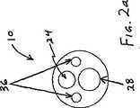
次に図2aを参照すると、超音波カテーテル10のある実施形態は、1個以上の流体流出開口部36を遠位ヘッド26内に備え、流体は、カテーテル本体のルーメン21から流出することが可能である。その他の実施形態(図示しない)は、遠位ヘッド26の開口部36のほかに、または遠位ヘッド26の開口部36の代わりに、カテーテル本体22の遠位端に、または遠位端付近に1個以上の類似の開口部を備えることができる。流出開口部26は、たとえば、1個以上のサイドアーム11、13を介してルーメン21内に注入することにより、冷却液がルーメン21を連続的または断続的に通過するのを促進する。ルーメン21を通して冷却液を超音波伝達部材24付近に注入する方法は、超音波伝達部材24の温度を制御して、使用時の過熱を防止するために用いられる。冷却液としては、生理食塩水およびその他を挙げることができるが、これだけに限らない。Referring now to FIG. 2a, an embodiment of the
実施形態によっては、ガイドワイヤの管28およびルーメン29は、一般に、カテーテル10が通るガイドワイヤの外径よりわずかに大きい内径を有するように構成される。次に、こうしたガイドワイヤの管28は、流体が遠位ヘッド26を通って流出することを可能にする代わりの手段または付加的な手段として使用されることができる。さらに他の実施形態では、カテーテルの遠位先端に、または遠位先端付近に形成された別個の流出開口部を有する1個以上の別個のルーメンは、酸素処理した潅水、薬剤またはその他の流体を血管、またはカテーテルが内部に配置されるその他の解剖学的構造内に注入するために形成されることができる。In some embodiments,
次に図4を参照すると、超音波カテーテル10のある実施形態は、カテーテル本体22に結合されると共に、超音波伝達部材24の一部分を包囲する遠位スリーブ72を備える。一般に、遠位スリーブ72は、任意の適切な材料から製造された中空円筒状部材を含み、こうした材料としてはポリマーが挙げられるが、これだけに限らない。スリーブ72は、ルーメン21内であって、カテーテル本体22の遠位端付近の位置において、カテーテル本体22に結合される。スリーブ72は、合理的な任意の手段を介して本体22に結合されることができるが、多くの場合、1つまたは複数の接着点において、カテーテル10のその他の構成部品を結合するための上記の接着剤などの接着剤を介して結合される。Referring now to FIG. 4, one embodiment of the
遠位スリーブ72は、超音波伝達部材24の一部分を囲み、カテーテル本体22と結合することにより、カテーテル10に安定性を加える。必ずしもカテーテル10を活用することにはならないし、カテーテル10の性能が改善されるわけでもないが、医師は、カテーテルを挿入後および/またはカテーテルの使用時に、カテーテルを半径方向に捻ったり、トルクを与えたりすることが多い。こうした捻転運動により、ガイドワイヤの管28は、管28がカテーテル本体22および伝達部材24に関連して移動する時に捻れることができるか、および/または圧潰することができる。遠位スリーブ72を伝達部材24の周囲に配置すると、カテーテル10の構成部品は、カテーテル10が捻れる時に一緒に移動し、その結果、ガイドワイヤの管28の捻転または圧潰を防止し、ガイドワイヤルーメン29の開通性を維持する。The
次に図5を参照すると、もう1つの実施形態の超音波カテーテル10は、遠位ヘッドのシース82を備える。遠位ヘッドのシース82は、一般に、遠位ヘッド26の一部分を囲む円筒状シースである。シース82は、接着点84における接着剤を介してガイドワイヤの管28に結合し、この接着点には、遠位ヘッド26の側部部分にある小さい孔86を介して接近する。シース82は、任意の適切な材料から製造して良いが、一般に、ガイドワイヤの管28を製造する材料と同じかまたは類似するポリマーから製造する。シース82を遠位ヘッド26内の孔86を通して管28に固定すると、管28と遠位ヘッド26との間の接続の安定性が強化される。したがって、遠位ヘッド26がカテーテル10から外れる可能性は少なくなり、デバイスの安全が強化される。シース82およびガイドワイヤの管28を同じかまたは類似する材料から形成すると、接着剤を介してこれらの間を確実に接続することが可能である。 Referring now to FIG. 5, another embodiment of the
次に図6を参照すると、カテーテル10のさらに他の実施形態は、遠位ヘッド固定具94を備える。遠位ヘッド固定具94は、金属、ポリマーまたはその他任意の適切な材料から製造されたワイヤまたは類似のデバイスを含むことができる。一般に、固定具94の遠位部分は、接着点96において遠位ヘッド26に結合し、固定具94の近位部分は、カテーテル本体22の末端の遠位端付近にある接着点92において、カテーテル本体22に結合する。したがって、遠位ヘッド26は、カテーテル本体22の末端の遠位端に対して自由に浮動する状態を保つが、さらに近位の位置92においてカテーテル本体22に固定される。固定は、遠位ヘッド26が、使用時にカテーテル10から外れないようにする上で役立つ。任意の適切な固定デバイスを使用することができ、こうしたデバイスは本発明の範囲内であると考えられる。Referring now to FIG. 6, yet another embodiment of the
近位端コネクタ装置12、超音波変換器14、超音波発生デバイス16および/またはその他の様々なタイプおよび構造は、超音波カテーテル10に結合され、カテーテル10を使用して血管閉塞を破壊する。こうした装置の詳細な説明は、たとえば、米国特許第5,267,954号および第5,380,274号に見出すことができ、これらの特許は、本願の発明人により発明され、上記のとおり、引用することにより本明細書に援用する。したがって、超音波カテーテル装置20および方法は、何らかの特定の変換器14、超音波発生器16、コネクタ装置12またはその他に限られない。Proximal end connector device 12,
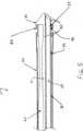
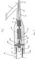
ところで、次に図7を参照すると、近位端コネクタ装置12の一実施形態は、適切には、中空の内側ボア44を含む筐体42を備える。ボア44は、その長さに沿って均一な内径を有することができ、別法によると、近位セグメント47、中間セグメント45および円位セグメント49などの複数のセグメント有することができ、各々のセグメントは、近位端コネクタ装置12の1個以上の様々な構成部品を囲むことができる。Referring now to FIG. 7, one embodiment of the proximal end connector device 12 suitably includes a
一般に、ボア44の近位セグメント47は、変換器筐体58および変換器のねじ54を介して超音波変換器56に取り付けることができるように構成される。したがって、近位セグメント47は、音響コネクタ48の近位部分を備え、この近位部分は、相補型の変換器ねじ54に接続するための音響コネクタのねじ52を備える。近位セグメント47および/または筐体42の近位端41は、変換器筐体58と結合することを可能にする任意の形状、直径または構成を有することができる。図7に示すように、近位セグメント47は、変換器筐体58が内部に嵌合することが可能なサイズの内径を有することができる。したがって、変換器筐体58および近位端41は、圧力嵌めを介して結合されることができる。その他の実施形態では、変換器筐体58および近位端41は、相補型のねじを介して接続されることができる。さらに他の実施形態では、変換器筐体58は、近位端41の外径周囲に嵌合することができる。任意の適切な構成の近位端を使用できることは、明白であるはずである。Generally, the
同様に、音響コネクタのねじ52は、相補型の変換器ねじ54と結合するための任意の適切なサイズ、形状および構成を有することができる。こうした結合は、相補型ねじ、スナップ嵌合機構または任意のその他の適切な手段を介して行なわれることができる。さもなければ、音響コネクタのねじ52および音響コネクタ48は、一般に、超音波エネルギーを超音波変換器56から超音波伝達部材24に伝達するように構成される。ピン50は、一般に、音響コネクタ48内に配置され、ボア44の近位セグメント47と中間セグメント45との間に配置される。Similarly, the
ボア44の中間セグメント45は、一般に、音響コネクタ48の一部分を囲み、音響コネクタ48は、超音波伝達部材24の遠位端、および吸収部材46の1つまたは複数の集合と結合し、吸収部材46は超音波伝達部材24の一部分を囲み、部材24の振動を減少させる。吸収部材46は、たとえば、1個以上のOリングを備えることができる。音響コネクタ48は、任意の適切な手段により超音波伝達部材24の遠位端に結合し、超音波エネルギーを変換器56から部材24に伝達する。The
吸収部材46は、超音波伝達部材24を全体的または部分的に周方向に包囲して、超音波エネルギーの伝達により生じる横断方向振動を抑制するように構成される。使用する吸収部材46の数、サイズおよび構成は、所望レベルの抑制に応じて決定され、任意の適切な構成または組合せを使用することができる。別法によると、吸収部材46ではなく、その他の抑制構造を使用することができ、したがって、近位コネクタ装置12は、吸収部材46の1つまたは複数の集合を使用することに限定されない。 The absorbing
ボア44の遠位セグメント49は、一般に、超音波伝達部材24の一部分を包囲し、吸収部材46の1つまたは複数の追加の集合も含むことができる。遠位セグメント49はYコネクタ15の一部分も含むことができ、近位端コネクタ装置12の筐体42の遠位端43に結合する。やはり、Yコネクタ15と装置12の遠位端42との結合は、相補型ねじ、圧力嵌めまたはその他の任意の適切な手段により行なわれることができる。Yコネクタ15のYコネクタのルーメン45は、超音波伝達部材24が通ることを可能にし、カテーテル本体のルーメン21と連通する。The distal segment 49 of the bore 44 generally surrounds a portion of the
Yコネクタ15は1個以上のサイドアーム11を有することができ、これは、ガイドワイヤの通過、冷却流体もしくはその他の任意の適切な流体の注入、またはその他の任意の適切な構造もしくは物質がサイドアーム11からYコネクタ15を通り、カテーテル10に至ることを可能にする。実施形態によっては、サイドアーム11のルーメンは、Yコネクタの主ルーメン45およびカテーテル本体のルーメン21と連通する。その他の実施形態では、サイドアーム11は、Yコネクタ15の別個のルーメン、およびカテーテル本体22と連通するルーメンを有することができる。
一般に、冷却液などの加圧流体は、サイドアーム11、Yコネクタのルーメン45およびカテーテル本体のルーメン21を通って注入されることができ、流体開口部36から流出する。こうした冷却液の温度および流量は、超音波伝達部材24の温度をその最適な動作範囲内の所望の温度に維持するために特に制御されることができる。特に、超音波伝達部材24が、特定の温度範囲内で最適な物理特性(たとえば、超弾性)を示す合金から形成される本発明の実施形態では、流体注入サイドアーム11から注入される冷却液の温度および流量は、超音波伝達部材24が最も望ましい物理特性を示す温度範囲内に超音波伝達部材24の温度を維持するように特に制御されることができる。たとえば、超音波伝達部材24が、マルテンサイト状態で超弾性を示すが、オーステナイト状態に遷移すると超弾性を失う形状記憶合金からされる場合、流体注入サイドアーム11から注入される冷却液の温度および流量を調節して、超音波伝達部材24の形状記憶合金を、合金がマルテンサイト状態を維持し、オーステナイト状態に遷移しない温度範囲内に維持することが望ましい。こうした形状記憶合金がマルテンサイト状態からオーステナイト状態に遷移する温度は、材料の「マルテンサイト遷移温度」として公知である。したがって、こうした実施形態では、サイドアーム11から注入される流体は、超音波伝達部材24の形状記憶合金をそのマルテンサイト遷移温度未満に維持する温度に保たれ、このような流量で注入される。Generally, pressurized fluid such as coolant passes through the side arm 11,
次に図7aを参照すると、近位端コネクタ装置12が分解側面図で示されている。この実施形態では、音響コネクタ48は、ダウエルピン50により筐体42内に保持される。他の実施形態では、ダウエルピン50は含まれなくてもよく、音響コネクタ48は、他の手段により筐体内に配置されることができる。さもなければ、図4aが、図4に関して上記で述べた様々な構成部品を簡単に示す。Referring now to FIG. 7a, the proximal end connector device 12 is shown in an exploded side view. In this embodiment, the
本発明について、様々な実施形態および実施例を特に参照して上記で説明したが、こうした実施形態には、本発明の精神または範囲から逸脱することなく、様々な追加、改良、削除および変更を加えることができると考えるべきである。したがって、合理的に予測可能な追加、削除、改良および変更は、以下の請求の範囲に定義する本発明の範囲に含むことを意図する。 Although the invention has been described above with particular reference to various embodiments and examples, various additions, improvements, deletions and modifications can be made to such embodiments without departing from the spirit or scope of the invention. It should be considered that it can be added. Accordingly, reasonably foreseeable additions, deletions, improvements and modifications are intended to be included within the scope of the invention as defined in the following claims.
Claims (7)
Translated fromJapanese近位端、遠位端および少なくとも1個のルーメンを有する長形の可撓性のカテーテル本体;
該カテーテル本体のルーメンを通って長軸方向に延びる超音波伝達部材であって、別個の超音波発生デバイスに接続可能な近位端を有する超音波伝達部材;
該超音波伝達部材の遠位端に結合された遠位ヘッド;ならびに
該カテーテル本体のルーメンの少なくとも一部分を通って長軸方向に延び、前記遠位ヘッドを通って少なくとも部分的に延びるガイドワイヤの管;
を備え、
該遠位ヘッドは、該カテーテル本体の遠位端に隣接して配置されるが該カテーテル本体の遠位端に直接的には固着されないか、または該カテーテル本体の遠位端が、該遠位ヘッドの少なくとも一部分に重なり合うが、該遠位ヘッドに直接的には固着されず、
該ガイドワイヤの管が、該遠位ヘッドに固着され、そして
該ガイドワイヤの管の外壁が、接着点において該カテーテル本体の内壁に固着される、超音波カテーテル。An ultrasound catheter for breaking an occlusion in a blood vessel, the ultrasound catheter comprising:
Proximal end, a distal end and an elongatedflexible catheter body having at least one lumen;
An ultrasound transmission member extending longitudinally through the lumen of the catheter body and having a proximal end connectable to a separate ultrasound generation device;
A distal head coupled to the distal end of the ultrasound transmission member; and a guidewire extending longitudinally through at least a portion of the lumen of the catheter body and extending at least partially through the distal head tube;
With
The distal head is disposed adjacent to the distal end of the catheter body but is not directly secured to the distal end of the catheter body, or the distal end of the catheter body is Overlaps at least a portion of the head, but does not adhere directly to the distal head,
An ultrasonic catheter, wherein the guidewire tube is secured to the distal head and the outer wall of the guidewire tube is secured to the inner wall of the catheter body at a point of attachment.
該カテーテル本体の近位端に結合し、中空ボアを有し、該中空ボアが、該カテーテル本体の少なくとも1個のルーメンと連通し、前記超音波伝達部材が、該カテーテル本体から該中空ボアの少なくとも一部分を通って近位に延びる長形剛性本体;
該超音波伝達部材の周囲を囲む中空ボア内に配置され、振動を吸収するための1個以上の吸収部材;および
該近位端コネクタアセンブリの近位端上にある音響コネクタ装置であって、該超音波伝達部材を別個の超音波発生装置に接続し、その結果、超音波エネルギーが、該超音波伝達部材を通って前記遠位ヘッドに伝達される音響コネクタ装置、
を備える、超音波カテーテル。The ultrasound catheter according to any one of claims 1 to 6, further comprising a proximal end connector assembly coupled to the proximal end of the catheter body. The connector assembly;
A hollow bore coupled to the proximal end of the catheter body, the hollow bore communicating with at least one lumen of the catheter body, and the ultrasonic transmission member extending from the catheter body to the hollow bore. An elongate rigid body extending proximally through at least a portion;
One or more absorbing members disposed within a hollow bore surrounding the ultrasonic transmission member for absorbing vibration; and an acoustic connector device on a proximal end of the proximal end connector assembly comprising: An acoustic connector device that connects the ultrasonic transmission member to a separate ultrasonic generator so that ultrasonic energy is transmitted through the ultrasonic transmission member to the distal head;
An ultrasonic catheter comprising:
Applications Claiming Priority (3)
| Application Number | Priority Date | Filing Date | Title |
|---|---|---|---|
| US10/229,371 | 2002-08-26 | ||
| US10/229,371US7137963B2 (en) | 2002-08-26 | 2002-08-26 | Ultrasound catheter for disrupting blood vessel obstructions |
| PCT/US2003/026976WO2004018019A2 (en) | 2002-08-26 | 2003-08-26 | Ultrasound catheter for disrupting blood vessel obstructions |
Related Child Applications (1)
| Application Number | Title | Priority Date | Filing Date |
|---|---|---|---|
| JP2010134566ADivisionJP5178780B2 (en) | 2002-08-26 | 2010-06-11 | Ultrasound catheter for breaking vascular occlusion |
Publications (3)
| Publication Number | Publication Date |
|---|---|
| JP2005537051A JP2005537051A (en) | 2005-12-08 |
| JP2005537051A5 JP2005537051A5 (en) | 2009-10-01 |
| JP4783014B2true JP4783014B2 (en) | 2011-09-28 |
Family
ID=31887658
Family Applications (2)
| Application Number | Title | Priority Date | Filing Date |
|---|---|---|---|
| JP2004531258AExpired - Fee RelatedJP4783014B2 (en) | 2002-08-26 | 2003-08-26 | Ultrasound catheter for breaking vascular occlusion |
| JP2010134566AExpired - Fee RelatedJP5178780B2 (en) | 2002-08-26 | 2010-06-11 | Ultrasound catheter for breaking vascular occlusion |
Family Applications After (1)
| Application Number | Title | Priority Date | Filing Date |
|---|---|---|---|
| JP2010134566AExpired - Fee RelatedJP5178780B2 (en) | 2002-08-26 | 2010-06-11 | Ultrasound catheter for breaking vascular occlusion |
Country Status (5)
| Country | Link |
|---|---|
| US (8) | US7137963B2 (en) |
| EP (1) | EP1553996B1 (en) |
| JP (2) | JP4783014B2 (en) |
| AU (1) | AU2003262952A1 (en) |
| WO (1) | WO2004018019A2 (en) |
Families Citing this family (203)
| Publication number | Priority date | Publication date | Assignee | Title |
|---|---|---|---|---|
| US6723063B1 (en) | 1998-06-29 | 2004-04-20 | Ekos Corporation | Sheath for use with an ultrasound element |
| US6582392B1 (en) | 1998-05-01 | 2003-06-24 | Ekos Corporation | Ultrasound assembly for use with a catheter |
| US6855123B2 (en) | 2002-08-02 | 2005-02-15 | Flow Cardia, Inc. | Therapeutic ultrasound system |
| US8506519B2 (en) | 1999-02-16 | 2013-08-13 | Flowcardia, Inc. | Pre-shaped therapeutic catheter |
| US6660013B2 (en)* | 1999-10-05 | 2003-12-09 | Omnisonics Medical Technologies, Inc. | Apparatus for removing plaque from blood vessels using ultrasonic energy |
| US20040097996A1 (en) | 1999-10-05 | 2004-05-20 | Omnisonics Medical Technologies, Inc. | Apparatus and method of removing occlusions using an ultrasonic medical device operating in a transverse mode |
| US6524251B2 (en) | 1999-10-05 | 2003-02-25 | Omnisonics Medical Technologies, Inc. | Ultrasonic device for tissue ablation and sheath for use therewith |
| US20040158150A1 (en)* | 1999-10-05 | 2004-08-12 | Omnisonics Medical Technologies, Inc. | Apparatus and method for an ultrasonic medical device for tissue remodeling |
| US6551337B1 (en) | 1999-10-05 | 2003-04-22 | Omnisonics Medical Technologies, Inc. | Ultrasonic medical device operating in a transverse mode |
| US8241274B2 (en) | 2000-01-19 | 2012-08-14 | Medtronic, Inc. | Method for guiding a medical device |
| US20030069502A1 (en) | 2001-05-29 | 2003-04-10 | Makin Inder Raj. S. | Ultrasound feedback in medically-treated patients |
| US7846096B2 (en)* | 2001-05-29 | 2010-12-07 | Ethicon Endo-Surgery, Inc. | Method for monitoring of medical treatment using pulse-echo ultrasound |
| US7285116B2 (en)* | 2004-05-15 | 2007-10-23 | Irvine Biomedical Inc. | Non-contact tissue ablation device and methods thereof |
| EP1647232B1 (en) | 2001-12-03 | 2011-08-17 | Ekos Corporation | Catheter with multiple ultrasound radiating members |
| CA2468835A1 (en)* | 2001-12-03 | 2003-06-12 | Ekos Corporation | Small vessel ultrasound catheter |
| WO2003072165A2 (en)* | 2002-02-28 | 2003-09-04 | Ekos Corporation | Ultrasound assembly for use with a catheter |
| US8226629B1 (en) | 2002-04-01 | 2012-07-24 | Ekos Corporation | Ultrasonic catheter power control |
| US8150519B2 (en) | 2002-04-08 | 2012-04-03 | Ardian, Inc. | Methods and apparatus for bilateral renal neuromodulation |
| US7617005B2 (en) | 2002-04-08 | 2009-11-10 | Ardian, Inc. | Methods and apparatus for thermally-induced renal neuromodulation |
| US20040082859A1 (en) | 2002-07-01 | 2004-04-29 | Alan Schaer | Method and apparatus employing ultrasound energy to treat body sphincters |
| US9955994B2 (en) | 2002-08-02 | 2018-05-01 | Flowcardia, Inc. | Ultrasound catheter having protective feature against breakage |
| US8133236B2 (en)* | 2006-11-07 | 2012-03-13 | Flowcardia, Inc. | Ultrasound catheter having protective feature against breakage |
| US7220233B2 (en) | 2003-04-08 | 2007-05-22 | Flowcardia, Inc. | Ultrasound catheter devices and methods |
| US7137963B2 (en) | 2002-08-26 | 2006-11-21 | Flowcardia, Inc. | Ultrasound catheter for disrupting blood vessel obstructions |
| US7335180B2 (en) | 2003-11-24 | 2008-02-26 | Flowcardia, Inc. | Steerable ultrasound catheter |
| US7604608B2 (en)* | 2003-01-14 | 2009-10-20 | Flowcardia, Inc. | Ultrasound catheter and methods for making and using same |
| US6942677B2 (en) | 2003-02-26 | 2005-09-13 | Flowcardia, Inc. | Ultrasound catheter apparatus |
| US7771372B2 (en)* | 2003-01-03 | 2010-08-10 | Ekos Corporation | Ultrasonic catheter with axial energy field |
| EP1619995A2 (en)* | 2003-04-22 | 2006-02-01 | Ekos Corporation | Ultrasound enhanced central venous catheter |
| DE202004021953U1 (en) | 2003-09-12 | 2013-06-19 | Vessix Vascular, Inc. | Selectable eccentric remodeling and / or ablation of atherosclerotic material |
| US7758510B2 (en) | 2003-09-19 | 2010-07-20 | Flowcardia, Inc. | Connector for securing ultrasound catheter to transducer |
| EP1713537A4 (en) | 2004-01-29 | 2009-04-29 | Ekos Corp | Method and apparatus for detecting vascular conditions with a catheter |
| US7794414B2 (en)* | 2004-02-09 | 2010-09-14 | Emigrant Bank, N.A. | Apparatus and method for an ultrasonic medical device operating in torsional and transverse modes |
| US20050187514A1 (en)* | 2004-02-09 | 2005-08-25 | Omnisonics Medical Technologies, Inc. | Apparatus and method for an ultrasonic medical device operating in a torsional mode |
| US20050228286A1 (en)* | 2004-04-07 | 2005-10-13 | Messerly Jeffrey D | Medical system having a rotatable ultrasound source and a piercing tip |
| US20050240123A1 (en)* | 2004-04-14 | 2005-10-27 | Mast T D | Ultrasound medical treatment system and method |
| US20050234438A1 (en)* | 2004-04-15 | 2005-10-20 | Mast T D | Ultrasound medical treatment system and method |
| US20050240124A1 (en)* | 2004-04-15 | 2005-10-27 | Mast T D | Ultrasound medical treatment system and method |
| US7494467B2 (en)* | 2004-04-16 | 2009-02-24 | Ethicon Endo-Surgery, Inc. | Medical system having multiple ultrasound transducers or an ultrasound transducer and an RF electrode |
| US20050267488A1 (en)* | 2004-05-13 | 2005-12-01 | Omnisonics Medical Technologies, Inc. | Apparatus and method for using an ultrasonic medical device to treat urolithiasis |
| US20050256410A1 (en)* | 2004-05-14 | 2005-11-17 | Omnisonics Medical Technologies, Inc. | Apparatus and method for an ultrasonic probe capable of bending with aid of a balloon |
| US20050256405A1 (en)* | 2004-05-17 | 2005-11-17 | Makin Inder Raj S | Ultrasound-based procedure for uterine medical treatment |
| US7883468B2 (en) | 2004-05-18 | 2011-02-08 | Ethicon Endo-Surgery, Inc. | Medical system having an ultrasound source and an acoustic coupling medium |
| US20050261587A1 (en)* | 2004-05-20 | 2005-11-24 | Makin Inder R S | Ultrasound medical system and method |
| US7951095B2 (en) | 2004-05-20 | 2011-05-31 | Ethicon Endo-Surgery, Inc. | Ultrasound medical system |
| US7473250B2 (en) | 2004-05-21 | 2009-01-06 | Ethicon Endo-Surgery, Inc. | Ultrasound medical system and method |
| US7695436B2 (en) | 2004-05-21 | 2010-04-13 | Ethicon Endo-Surgery, Inc. | Transmit apodization of an ultrasound transducer array |
| US7806839B2 (en) | 2004-06-14 | 2010-10-05 | Ethicon Endo-Surgery, Inc. | System and method for ultrasound therapy using grating lobes |
| US7540852B2 (en) | 2004-08-26 | 2009-06-02 | Flowcardia, Inc. | Ultrasound catheter devices and methods |
| GB0419954D0 (en) | 2004-09-08 | 2004-10-13 | Advotek Medical Devices Ltd | System for directing therapy |
| US9713730B2 (en) | 2004-09-10 | 2017-07-25 | Boston Scientific Scimed, Inc. | Apparatus and method for treatment of in-stent restenosis |
| US8396548B2 (en) | 2008-11-14 | 2013-03-12 | Vessix Vascular, Inc. | Selective drug delivery in a lumen |
| US20060116610A1 (en)* | 2004-11-30 | 2006-06-01 | Omnisonics Medical Technologies, Inc. | Apparatus and method for an ultrasonic medical device with variable frequency drive |
| US8221343B2 (en) | 2005-01-20 | 2012-07-17 | Flowcardia, Inc. | Vibrational catheter devices and methods for making same |
| US20070016184A1 (en)* | 2005-07-14 | 2007-01-18 | Ethicon Endo-Surgery, Inc. | Medical-treatment electrode assembly and method for medical treatment |
| US20070191713A1 (en) | 2005-10-14 | 2007-08-16 | Eichmann Stephen E | Ultrasonic device for cutting and coagulating |
| US7621930B2 (en) | 2006-01-20 | 2009-11-24 | Ethicon Endo-Surgery, Inc. | Ultrasound medical instrument having a medical ultrasonic blade |
| US20080039728A1 (en)* | 2006-03-09 | 2008-02-14 | Dharmendra Pal | Catheters and Related Systems and Methods |
| US9282984B2 (en) | 2006-04-05 | 2016-03-15 | Flowcardia, Inc. | Therapeutic ultrasound system |
| US20130190676A1 (en) | 2006-04-20 | 2013-07-25 | Limflow Gmbh | Devices and methods for fluid flow through body passages |
| EP2015846A2 (en) | 2006-04-24 | 2009-01-21 | Ekos Corporation | Ultrasound therapy system |
| US8019435B2 (en) | 2006-05-02 | 2011-09-13 | Boston Scientific Scimed, Inc. | Control of arterial smooth muscle tone |
| US10499937B2 (en) | 2006-05-19 | 2019-12-10 | Recor Medical, Inc. | Ablation device with optimized input power profile and method of using the same |
| US20080039746A1 (en) | 2006-05-25 | 2008-02-14 | Medtronic, Inc. | Methods of using high intensity focused ultrasound to form an ablated tissue area containing a plurality of lesions |
| EP2076198A4 (en) | 2006-10-18 | 2009-12-09 | Minnow Medical Inc | Inducing desirable temperature effects on body tissue |
| JP5559539B2 (en) | 2006-10-18 | 2014-07-23 | べシックス・バスキュラー・インコーポレイテッド | System that induces desirable temperature effects on body tissue |
| EP2455036B1 (en) | 2006-10-18 | 2015-07-15 | Vessix Vascular, Inc. | Tuned RF energy and electrical tissue characterization for selective treatment of target tissues |
| US8192363B2 (en)* | 2006-10-27 | 2012-06-05 | Ekos Corporation | Catheter with multiple ultrasound radiating members |
| US8246643B2 (en) | 2006-11-07 | 2012-08-21 | Flowcardia, Inc. | Ultrasound catheter having improved distal end |
| US10182833B2 (en) | 2007-01-08 | 2019-01-22 | Ekos Corporation | Power parameters for ultrasonic catheter |
| ES2538110T3 (en) | 2007-01-08 | 2015-06-17 | Ekos Corporation | Power parameters for ultrasonic catheter |
| EP2170181B1 (en) | 2007-06-22 | 2014-04-16 | Ekos Corporation | Method and apparatus for treatment of intracranial hemorrhages |
| WO2009141810A2 (en)* | 2008-05-23 | 2009-11-26 | Oscillon Ltd | Method and device for recanalization of total occlusions |
| WO2010019481A1 (en) | 2008-08-11 | 2010-02-18 | Conceptx Medical, Inc. | Systems and methods for treating dyspnea, including via electrical afferent signal blocking |
| WO2010021951A2 (en) | 2008-08-18 | 2010-02-25 | The Brigham And Women's Hospital, Inc. | Integrated surgical sampling probe |
| EP2355737B1 (en) | 2008-11-17 | 2021-08-11 | Boston Scientific Scimed, Inc. | Selective accumulation of energy without knowledge of tissue topography |
| WO2010080886A1 (en) | 2009-01-09 | 2010-07-15 | Recor Medical, Inc. | Methods and apparatus for treatment of mitral valve in insufficiency |
| US8226566B2 (en) | 2009-06-12 | 2012-07-24 | Flowcardia, Inc. | Device and method for vascular re-entry |
| PL2448636T3 (en)* | 2009-07-03 | 2014-11-28 | Ekos Corp | Power parameters for ultrasonic catheter |
| WO2011022251A2 (en)* | 2009-08-21 | 2011-02-24 | Boston Scientific Scimed, Inc. | Ultrasound energy delivery assembly |
| US20130023897A1 (en)* | 2009-10-06 | 2013-01-24 | Michael P Wallace | Devices and Methods for Endovascular Therapies |
| US11039845B2 (en)* | 2009-10-06 | 2021-06-22 | Cardioprolific Inc. | Methods and devices for endovascular therapy |
| US20110237982A1 (en)* | 2009-10-06 | 2011-09-29 | Wallace Michael P | Ultrasound-enhanced stenosis therapy |
| US20130345617A1 (en)* | 2009-10-06 | 2013-12-26 | Michael P. Wallace | Methods and devices for removal of tissue, blood clots and liquids from the patient |
| US20110105960A1 (en)* | 2009-10-06 | 2011-05-05 | Wallace Michael P | Ultrasound-enhanced Stenosis therapy |
| US8740835B2 (en) | 2010-02-17 | 2014-06-03 | Ekos Corporation | Treatment of vascular occlusions using ultrasonic energy and microbubbles |
| WO2011126580A2 (en) | 2010-04-09 | 2011-10-13 | Minnow Medical, Inc. | Power generating and control apparatus for the treatment of tissue |
| US9192790B2 (en) | 2010-04-14 | 2015-11-24 | Boston Scientific Scimed, Inc. | Focused ultrasonic renal denervation |
| US8473067B2 (en) | 2010-06-11 | 2013-06-25 | Boston Scientific Scimed, Inc. | Renal denervation and stimulation employing wireless vascular energy transfer arrangement |
| US9408661B2 (en) | 2010-07-30 | 2016-08-09 | Patrick A. Haverkost | RF electrodes on multiple flexible wires for renal nerve ablation |
| US9358365B2 (en) | 2010-07-30 | 2016-06-07 | Boston Scientific Scimed, Inc. | Precision electrode movement control for renal nerve ablation |
| US9463062B2 (en) | 2010-07-30 | 2016-10-11 | Boston Scientific Scimed, Inc. | Cooled conductive balloon RF catheter for renal nerve ablation |
| US9084609B2 (en) | 2010-07-30 | 2015-07-21 | Boston Scientific Scime, Inc. | Spiral balloon catheter for renal nerve ablation |
| US9155589B2 (en) | 2010-07-30 | 2015-10-13 | Boston Scientific Scimed, Inc. | Sequential activation RF electrode set for renal nerve ablation |
| US10238833B2 (en) | 2010-08-12 | 2019-03-26 | C. R. Bard, Inc. | Access port and catheter assembly including catheter distal portion stability features |
| BR112013003333B1 (en) | 2010-08-12 | 2021-12-28 | C.R. Bard, Inc | CATHETER SET INCLUDING DISTAL PORTION STABILITY CHARACTERISTICS |
| JP6291253B2 (en) | 2010-08-27 | 2018-03-14 | イーコス・コーポレイシヨン | Ultrasound catheter |
| US8974451B2 (en) | 2010-10-25 | 2015-03-10 | Boston Scientific Scimed, Inc. | Renal nerve ablation using conductive fluid jet and RF energy |
| US9220558B2 (en) | 2010-10-27 | 2015-12-29 | Boston Scientific Scimed, Inc. | RF renal denervation catheter with multiple independent electrodes |
| US9028485B2 (en) | 2010-11-15 | 2015-05-12 | Boston Scientific Scimed, Inc. | Self-expanding cooling electrode for renal nerve ablation |
| US9668811B2 (en) | 2010-11-16 | 2017-06-06 | Boston Scientific Scimed, Inc. | Minimally invasive access for renal nerve ablation |
| US9089350B2 (en) | 2010-11-16 | 2015-07-28 | Boston Scientific Scimed, Inc. | Renal denervation catheter with RF electrode and integral contrast dye injection arrangement |
| US9326751B2 (en) | 2010-11-17 | 2016-05-03 | Boston Scientific Scimed, Inc. | Catheter guidance of external energy for renal denervation |
| US9060761B2 (en) | 2010-11-18 | 2015-06-23 | Boston Scientific Scime, Inc. | Catheter-focused magnetic field induced renal nerve ablation |
| US9023034B2 (en) | 2010-11-22 | 2015-05-05 | Boston Scientific Scimed, Inc. | Renal ablation electrode with force-activatable conduction apparatus |
| US9192435B2 (en) | 2010-11-22 | 2015-11-24 | Boston Scientific Scimed, Inc. | Renal denervation catheter with cooled RF electrode |
| US20120157993A1 (en) | 2010-12-15 | 2012-06-21 | Jenson Mark L | Bipolar Off-Wall Electrode Device for Renal Nerve Ablation |
| US9220561B2 (en) | 2011-01-19 | 2015-12-29 | Boston Scientific Scimed, Inc. | Guide-compatible large-electrode catheter for renal nerve ablation with reduced arterial injury |
| US11458290B2 (en) | 2011-05-11 | 2022-10-04 | Ekos Corporation | Ultrasound system |
| CN103813745B (en) | 2011-07-20 | 2016-06-29 | 波士顿科学西美德公司 | In order to visualize, be directed at and to melt transcutaneous device and the method for nerve |
| EP2734264B1 (en) | 2011-07-22 | 2018-11-21 | Boston Scientific Scimed, Inc. | Nerve modulation system with a nerve modulation element positionable in a helical guide |
| US8974478B2 (en) | 2011-09-20 | 2015-03-10 | Covidien Lp | Ultrasonic surgical system having a fluid cooled blade and related cooling methods therefor |
| WO2013055826A1 (en) | 2011-10-10 | 2013-04-18 | Boston Scientific Scimed, Inc. | Medical devices including ablation electrodes |
| US9420955B2 (en) | 2011-10-11 | 2016-08-23 | Boston Scientific Scimed, Inc. | Intravascular temperature monitoring system and method |
| EP2765940B1 (en) | 2011-10-11 | 2015-08-26 | Boston Scientific Scimed, Inc. | Off-wall electrode device for nerve modulation |
| US9364284B2 (en) | 2011-10-12 | 2016-06-14 | Boston Scientific Scimed, Inc. | Method of making an off-wall spacer cage |
| US9162046B2 (en) | 2011-10-18 | 2015-10-20 | Boston Scientific Scimed, Inc. | Deflectable medical devices |
| EP2768568B1 (en) | 2011-10-18 | 2020-05-06 | Boston Scientific Scimed, Inc. | Integrated crossing balloon catheter |
| US8951251B2 (en) | 2011-11-08 | 2015-02-10 | Boston Scientific Scimed, Inc. | Ostial renal nerve ablation |
| WO2013074813A1 (en) | 2011-11-15 | 2013-05-23 | Boston Scientific Scimed, Inc. | Device and methods for renal nerve modulation monitoring |
| US9119632B2 (en) | 2011-11-21 | 2015-09-01 | Boston Scientific Scimed, Inc. | Deflectable renal nerve ablation catheter |
| US9265969B2 (en) | 2011-12-21 | 2016-02-23 | Cardiac Pacemakers, Inc. | Methods for modulating cell function |
| US9028472B2 (en) | 2011-12-23 | 2015-05-12 | Vessix Vascular, Inc. | Methods and apparatuses for remodeling tissue of or adjacent to a body passage |
| TWI482613B (en) | 2011-12-27 | 2015-05-01 | Ind Tech Res Inst | Signal analysis method, method for analyzing ultrasound image, and ultrasound imaging system using the same |
| EP2797534A1 (en) | 2011-12-28 | 2014-11-05 | Boston Scientific Scimed, Inc. | Device and methods for nerve modulation using a novel ablation catheter with polymeric ablative elements |
| US9050106B2 (en) | 2011-12-29 | 2015-06-09 | Boston Scientific Scimed, Inc. | Off-wall electrode device and methods for nerve modulation |
| US9603615B2 (en) | 2012-01-18 | 2017-03-28 | C.R. Bard, Inc. | Vascular re-entry device |
| WO2013163322A1 (en) | 2012-04-24 | 2013-10-31 | Cibiem, Inc. | Endovascular catheters and methods for carotid body ablation |
| US10660703B2 (en) | 2012-05-08 | 2020-05-26 | Boston Scientific Scimed, Inc. | Renal nerve modulation devices |
| WO2013181660A1 (en) | 2012-06-01 | 2013-12-05 | Cibiem, Inc. | Methods and devices for cryogenic carotid body ablation |
| EP2854681A4 (en) | 2012-06-01 | 2016-02-17 | Cibiem Inc | Percutaneous methods and devices for carotid body ablation |
| WO2014005155A1 (en) | 2012-06-30 | 2014-01-03 | Cibiem, Inc. | Carotid body ablation via directed energy |
| CN104755010A (en)* | 2012-07-04 | 2015-07-01 | 西比姆公司 | Devices and systems for carotid body ablation |
| RU2640564C2 (en) | 2012-08-02 | 2018-01-09 | Бард Периферэл Васкьюлар | Ultrasonic catheter system |
| US10321946B2 (en) | 2012-08-24 | 2019-06-18 | Boston Scientific Scimed, Inc. | Renal nerve modulation devices with weeping RF ablation balloons |
| CN104780859B (en) | 2012-09-17 | 2017-07-25 | 波士顿科学西美德公司 | Self-positioning electrode systems and methods for renal neuromodulation |
| US10398464B2 (en) | 2012-09-21 | 2019-09-03 | Boston Scientific Scimed, Inc. | System for nerve modulation and innocuous thermal gradient nerve block |
| US10549127B2 (en) | 2012-09-21 | 2020-02-04 | Boston Scientific Scimed, Inc. | Self-cooling ultrasound ablation catheter |
| CN104869930B (en) | 2012-10-10 | 2020-12-25 | 波士顿科学国际有限公司 | Renal neuromodulation apparatus and methods |
| US9173667B2 (en) | 2012-10-16 | 2015-11-03 | Med-Sonics Corporation | Apparatus and methods for transferring ultrasonic energy to a bodily tissue |
| US9339284B2 (en) | 2012-11-06 | 2016-05-17 | Med-Sonics Corporation | Systems and methods for controlling delivery of ultrasonic energy to a bodily tissue |
| WO2014105754A1 (en) | 2012-12-28 | 2014-07-03 | Flowcardia, Inc. | Drug delivery via mechanical vibration balloon |
| US10835367B2 (en) | 2013-03-08 | 2020-11-17 | Limflow Gmbh | Devices for fluid flow through body passages |
| CA2898879C (en) | 2013-03-08 | 2023-05-02 | Limflow Gmbh | Methods and systems for providing or maintaining fluid flow through body passages |
| WO2014163987A1 (en) | 2013-03-11 | 2014-10-09 | Boston Scientific Scimed, Inc. | Medical devices for modulating nerves |
| WO2014143571A1 (en) | 2013-03-11 | 2014-09-18 | Boston Scientific Scimed, Inc. | Medical devices for modulating nerves |
| US9808311B2 (en) | 2013-03-13 | 2017-11-07 | Boston Scientific Scimed, Inc. | Deflectable medical devices |
| WO2014159274A1 (en) | 2013-03-14 | 2014-10-02 | Ekos Corporation | Method and apparatus for drug delivery to a target site |
| CN105228546B (en) | 2013-03-15 | 2017-11-14 | 波士顿科学国际有限公司 | Medical devices and methods for treating hypertension utilizing impedance compensation |
| US10265122B2 (en) | 2013-03-15 | 2019-04-23 | Boston Scientific Scimed, Inc. | Nerve ablation devices and related methods of use |
| EP2967734B1 (en) | 2013-03-15 | 2019-05-15 | Boston Scientific Scimed, Inc. | Methods and apparatuses for remodeling tissue of or adjacent to a body passage |
| CN105473092B (en) | 2013-06-21 | 2019-05-17 | 波士顿科学国际有限公司 | The medical instrument for renal nerve ablation with rotatable shaft |
| CN105473091B (en) | 2013-06-21 | 2020-01-21 | 波士顿科学国际有限公司 | Renal denervation balloon catheter with co-movable electrode supports |
| US9707036B2 (en) | 2013-06-25 | 2017-07-18 | Boston Scientific Scimed, Inc. | Devices and methods for nerve modulation using localized indifferent electrodes |
| CN105358084B (en) | 2013-07-01 | 2018-11-09 | 波士顿科学国际有限公司 | Medical instrument for renal nerve ablation |
| CN105377169B (en) | 2013-07-11 | 2019-04-19 | 波士顿科学国际有限公司 | Devices and methods for neuromodulation |
| US10413357B2 (en) | 2013-07-11 | 2019-09-17 | Boston Scientific Scimed, Inc. | Medical device with stretchable electrode assemblies |
| US9925001B2 (en) | 2013-07-19 | 2018-03-27 | Boston Scientific Scimed, Inc. | Spiral bipolar electrode renal denervation balloon |
| US10342609B2 (en) | 2013-07-22 | 2019-07-09 | Boston Scientific Scimed, Inc. | Medical devices for renal nerve ablation |
| US10695124B2 (en) | 2013-07-22 | 2020-06-30 | Boston Scientific Scimed, Inc. | Renal nerve ablation catheter having twist balloon |
| CN105473093B (en) | 2013-08-22 | 2019-02-05 | 波士顿科学国际有限公司 | Flexible circuit with improved adhesion to renal neuromodulation balloon |
| US9895194B2 (en) | 2013-09-04 | 2018-02-20 | Boston Scientific Scimed, Inc. | Radio frequency (RF) balloon catheter having flushing and cooling capability |
| EP3043733A1 (en) | 2013-09-13 | 2016-07-20 | Boston Scientific Scimed, Inc. | Ablation balloon with vapor deposited cover layer |
| EP3057488B1 (en) | 2013-10-14 | 2018-05-16 | Boston Scientific Scimed, Inc. | High resolution cardiac mapping electrode array catheter |
| US11246654B2 (en) | 2013-10-14 | 2022-02-15 | Boston Scientific Scimed, Inc. | Flexible renal nerve ablation devices and related methods of use and manufacture |
| US9770606B2 (en) | 2013-10-15 | 2017-09-26 | Boston Scientific Scimed, Inc. | Ultrasound ablation catheter with cooling infusion and centering basket |
| US9962223B2 (en) | 2013-10-15 | 2018-05-08 | Boston Scientific Scimed, Inc. | Medical device balloon |
| EP3057521B1 (en) | 2013-10-18 | 2020-03-25 | Boston Scientific Scimed, Inc. | Balloon catheters with flexible conducting wires |
| CN105658163B (en) | 2013-10-25 | 2020-08-18 | 波士顿科学国际有限公司 | Embedded thermocouple in denervation flexible circuit |
| WO2015088012A1 (en)* | 2013-12-13 | 2015-06-18 | オリンパス株式会社 | Treatment instrument and treatment system |
| EP3091922B1 (en) | 2014-01-06 | 2018-10-17 | Boston Scientific Scimed, Inc. | Tear resistant flex circuit assembly |
| CN106572881B (en) | 2014-02-04 | 2019-07-26 | 波士顿科学国际有限公司 | Alternative placement of thermal sensors on bipolar electrodes |
| US11000679B2 (en) | 2014-02-04 | 2021-05-11 | Boston Scientific Scimed, Inc. | Balloon protection and rewrapping devices and related methods of use |
| EP3116408B1 (en) | 2014-03-12 | 2018-12-19 | Cibiem, Inc. | Ultrasound ablation catheter |
| US9545263B2 (en) | 2014-06-19 | 2017-01-17 | Limflow Gmbh | Devices and methods for treating lower extremity vasculature |
| US10092742B2 (en) | 2014-09-22 | 2018-10-09 | Ekos Corporation | Catheter system |
| WO2016081025A1 (en) | 2014-11-19 | 2016-05-26 | C.R. Bard, Inc. | Ultrasound transducer system for use with an ultrasound catheter |
| WO2016081026A1 (en) | 2014-11-19 | 2016-05-26 | C.R. Bard, Inc. | Ultrasound catheter and system with multiple function modes |
| DE102014225939A1 (en)* | 2014-12-15 | 2016-06-16 | Raumedic Ag | Hose system for medical use |
| US10806922B2 (en)* | 2015-02-12 | 2020-10-20 | Medtronic, Inc | Medical access tools, assemblies, and methods |
| US20160287223A1 (en)* | 2015-04-01 | 2016-10-06 | Boston Scientific Scimed, Inc. | Pulmonary biopsy devices |
| US9763684B2 (en) | 2015-04-02 | 2017-09-19 | Med-Sonics Corporation | Devices and methods for removing occlusions from a bodily cavity |
| CN107708581B (en) | 2015-06-10 | 2021-11-19 | Ekos公司 | Ultrasonic wave guide tube |
| EP3468478B1 (en) | 2016-06-09 | 2025-02-12 | C. R. Bard, Inc. | Systems for correcting and preventing occlusion in a catheter |
| CN106214216B (en)* | 2016-08-31 | 2019-01-25 | 赵萍萍 | A kind of thrombus removing instrument |
| US10357262B2 (en) | 2016-11-14 | 2019-07-23 | C. R. Bard, Inc. | Systems and methods to modify intravascular lesions |
| US20180140321A1 (en)* | 2016-11-23 | 2018-05-24 | C. R. Bard, Inc. | Catheter With Retractable Sheath And Methods Thereof |
| US11596726B2 (en) | 2016-12-17 | 2023-03-07 | C.R. Bard, Inc. | Ultrasound devices for removing clots from catheters and related methods |
| US10758256B2 (en) | 2016-12-22 | 2020-09-01 | C. R. Bard, Inc. | Ultrasonic endovascular catheter |
| US10582983B2 (en) | 2017-02-06 | 2020-03-10 | C. R. Bard, Inc. | Ultrasonic endovascular catheter with a controllable sheath |
| EP3609415B1 (en) | 2017-04-10 | 2023-08-23 | LimFlow GmbH | Devices for treating lower extremity vasculature |
| WO2019045705A1 (en)* | 2017-08-30 | 2019-03-07 | C.R. Bard, Inc. | Interventional medical device having reduced fracture risk |
| MX2020003574A (en) | 2017-09-29 | 2020-08-03 | Bard Inc C R | Apparatus and method for tracking a medical ultrasonic object. |
| US20190321061A1 (en)* | 2018-04-23 | 2019-10-24 | Justin Panian | Ultrasound Vessel Preparation |
| AU2019347721B2 (en)* | 2018-09-24 | 2025-07-10 | Stryker European Operations Holdings Llc | Ultrasonic tip with protrusion defining a preaspiration hole |
| SG11202102500UA (en) | 2018-10-09 | 2021-04-29 | Limflow Gmbh | Devices and methods for catheter alignment |
| JP2022543732A (en)* | 2019-06-18 | 2022-10-14 | シー・アール・バード・インコーポレーテッド | Ultrasound system and method with improved occlusion engagement during crossing and atherectomy procedures |
| US11160959B2 (en)* | 2019-10-23 | 2021-11-02 | Imam Abdulrahman Bin Faisal University | Flexible-tip-catheter (bisher catheter) |
| EP4051174A4 (en) | 2019-11-01 | 2023-11-22 | LimFlow GmbH | Devices and methods for increasing blood perfusion to a distal extremity |
| GB202006665D0 (en)* | 2020-05-05 | 2020-06-17 | Versono Medical Ltd | Treatment of ischaemia |
| USD974558S1 (en) | 2020-12-18 | 2023-01-03 | Stryker European Operations Limited | Ultrasonic knife |
| US12290264B2 (en) | 2021-01-22 | 2025-05-06 | Ultratellege Usa Co., Limited | Dual ultrasonic catheter and methods of use |
| CN115317024A (en)* | 2022-09-01 | 2022-11-11 | 深圳北芯生命科技股份有限公司 | A Novel Intravascular Ultrasound Diagnostic Catheter |
Citations (7)
| Publication number | Priority date | Publication date | Assignee | Title |
|---|---|---|---|---|
| JPS4920563A (en)* | 1972-06-19 | 1974-02-23 | ||
| JPH07500752A (en)* | 1991-11-04 | 1995-01-26 | バクスター インターナショナル インコーポレーテッド | Guidewire-entering ultrasonic ablation device |
| JPH07509146A (en)* | 1992-02-27 | 1995-10-12 | アンジオソニックス インコーポレイテッド | Ultrasonic transmission device |
| US5989208A (en)* | 1997-05-16 | 1999-11-23 | Nita; Henry | Therapeutic ultrasound system |
| JP2000291543A (en)* | 1999-04-05 | 2000-10-17 | Rozensutaa Kk | Air pump for wine bottle |
| US6296620B1 (en)* | 1999-12-09 | 2001-10-02 | Advanced Cardiovascular Systems, Inc. | Polymer blends for ultrasonic catheters |
| US6423026B1 (en)* | 1999-12-09 | 2002-07-23 | Advanced Cardiovascular Systems, Inc. | Catheter stylet |
Family Cites Families (304)
| Publication number | Priority date | Publication date | Assignee | Title |
|---|---|---|---|---|
| GB1106957A (en) | 1965-04-06 | 1968-03-20 | Oleg Gavrilovich Balaev | Instrument for crushing concretions in the urinary bladder |
| US3433226A (en) | 1965-07-21 | 1969-03-18 | Aeroprojects Inc | Vibratory catheterization apparatus and method of using |
| US3585062A (en)* | 1967-07-18 | 1971-06-15 | Stevens & Co Inc J P | Method of producing a heat-sealable non-thermoplastic foam material |
| US3565062A (en) | 1968-06-13 | 1971-02-23 | Ultrasonic Systems | Ultrasonic method and apparatus for removing cholesterol and other deposits from blood vessels and the like |
| US3565082A (en)* | 1968-06-26 | 1971-02-23 | Deere & Co | Corn-husking mechanism |
| US3631848A (en) | 1968-09-04 | 1972-01-04 | Us Catheter & Instr Corp | Extensible catheter |
| US3612038A (en) | 1969-02-03 | 1971-10-12 | Becton Dickinson Co | Preformable catheter package assembly and method of preforming |
| US3719737A (en) | 1970-12-09 | 1973-03-06 | Bard Inc C R | Method of making a preformed curved epidural catheter |
| DE2219790C3 (en) | 1972-04-22 | 1974-11-07 | R Pohlman | Device for generating brittle fractures in hard stones |
| US3839841A (en) | 1972-07-13 | 1974-10-08 | K Amplatz | Method for forming and sterilizing catheters |
| DE2242863A1 (en) | 1972-08-31 | 1974-03-14 | Karl Storz | SURGICAL ELEMENT FOR CRUSHING STONES IN THE HUMAN BODY BY ULTRASOUND |
| DE2256127A1 (en) | 1972-11-16 | 1974-05-22 | Reimar Prof Dr Phil Pohlman | DEVICE FOR CRUSHING HARNSTONE |
| US3891591A (en) | 1973-08-13 | 1975-06-24 | Du Pont | Coating compositions |
| DE2438648A1 (en) | 1974-08-12 | 1976-02-26 | Reimar Prof Dr Phil Pohlman | Dispersal and removal of thromboses within blood vessels - using ultrasonic sound conducting cannulae bundle with central suction opening and transmission facility for infusion liquids |
| US4016882A (en) | 1975-03-05 | 1977-04-12 | Cavitron Corporation | Neurosonic aspirator and method |
| US4033331A (en) | 1975-07-17 | 1977-07-05 | Guss Stephen B | Cardiac catheter and method of using same |
| US4425115A (en) | 1977-12-19 | 1984-01-10 | Wuchinich David G | Ultrasonic resonant vibrator |
| US4337090A (en) | 1980-09-05 | 1982-06-29 | Raychem Corporation | Heat recoverable nickel/titanium alloy with improved stability and machinability |
| US4368410A (en) | 1980-10-14 | 1983-01-11 | Dynawave Corporation | Ultrasound therapy device |
| US4417578A (en) | 1981-03-20 | 1983-11-29 | Surgical Design | Ultrasonic transducer with energy shielding |
| US4505787A (en)* | 1981-07-13 | 1985-03-19 | Super Fuel Systems Incorporated | Process for production of a carbide by-product with microwave energy and aluminum by electrolysis |
| GB2116046B (en) | 1982-03-04 | 1985-05-22 | Wolf Gmbh Richard | Apparatus for disintegrating and removing calculi |
| US4565589A (en) | 1982-03-05 | 1986-01-21 | Raychem Corporation | Nickel/titanium/copper shape memory alloy |
| JPS5991476A (en) | 1982-11-17 | 1984-05-26 | 東京電力株式会社 | training simulator |
| US4565787A (en) | 1983-05-09 | 1986-01-21 | The United States Of America As Represented By The Secretary Of The Army | High performance liquid chromatography (HPLC) analysis of sulfur mustards and their decomposition by-products by derivatization |
| GB8318072D0 (en)* | 1983-07-04 | 1983-08-03 | Lepetit Spa | Water-soluble rifampicin derivatives |
| US4665906A (en) | 1983-10-14 | 1987-05-19 | Raychem Corporation | Medical devices incorporating sim alloy elements |
| US4505767A (en) | 1983-10-14 | 1985-03-19 | Raychem Corporation | Nickel/titanium/vanadium shape memory alloy |
| JPS6086822A (en) | 1983-10-19 | 1985-05-16 | Furukawa Electric Co Ltd:The | Semiconductor thin film vapor phase growth equipment |
| US4572184A (en) | 1983-10-28 | 1986-02-25 | Blackstone Corporation | Wave guide attachment means and methods |
| US5114414A (en) | 1984-09-18 | 1992-05-19 | Medtronic, Inc. | Low profile steerable catheter |
| JPS61272045A (en) | 1985-05-29 | 1986-12-02 | 住友ベークライト株式会社 | Ultrasonic operation apparatus |
| US4700705A (en) | 1985-08-12 | 1987-10-20 | Intravascular Surgical Instruments, Inc. | Catheter based surgical methods and apparatus therefor |
| US4664112A (en) | 1985-08-12 | 1987-05-12 | Intravascular Surgical Instruments, Inc. | Catheter based surgical methods and apparatus therefor |
| US4679558A (en) | 1985-08-12 | 1987-07-14 | Intravascular Surgical Instruments, Inc. | Catheter based surgical methods and apparatus therefor |
| US4750902A (en) | 1985-08-28 | 1988-06-14 | Sonomed Technology, Inc. | Endoscopic ultrasonic aspirators |
| US5000185A (en) | 1986-02-28 | 1991-03-19 | Cardiovascular Imaging Systems, Inc. | Method for intravascular two-dimensional ultrasonography and recanalization |
| US4865908A (en)* | 1986-03-07 | 1989-09-12 | Mobil Oil Corporation | Coated, oriented polymer film laminate |
| FR2595860A1 (en) | 1986-03-17 | 1987-09-18 | Kodak Pathe | COMPENSATION FILTER FOR RADIOGRAPHY |
| US4827911A (en) | 1986-04-02 | 1989-05-09 | Cooper Lasersonics, Inc. | Method and apparatus for ultrasonic surgical fragmentation and removal of tissue |
| US6702750B2 (en) | 1986-04-15 | 2004-03-09 | Cardiovascular Imaging Systems, Inc. | Angioplasty apparatus facilitating rapid exchanges and methods |
| US4721117A (en) | 1986-04-25 | 1988-01-26 | Advanced Cardiovascular Systems, Inc. | Torsionally stabilized guide wire with outer jacket |
| US4808153A (en) | 1986-11-17 | 1989-02-28 | Ultramed Corporation | Device for removing plaque from arteries |
| US5058570A (en) | 1986-11-27 | 1991-10-22 | Sumitomo Bakelite Company Limited | Ultrasonic surgical apparatus |
| US4838853A (en) | 1987-02-05 | 1989-06-13 | Interventional Technologies Inc. | Apparatus for trimming meniscus |
| US4936845A (en) | 1987-03-17 | 1990-06-26 | Cordis Corporation | Catheter system having distal tip for opening obstructions |
| US5116350B1 (en) | 1987-03-17 | 1997-06-17 | Cordis Corp | Catheter system having distal tip for opening obstructions |
| US4923462A (en) | 1987-03-17 | 1990-05-08 | Cordis Corporation | Catheter system having a small diameter rotatable drive member |
| SE459711B (en) | 1987-03-20 | 1989-07-31 | Swedemed Ab | EQUIPMENT FOR USE IN SURGICAL INTERVENTIONS TO DISPOSE TISSUE |
| US4811743A (en) | 1987-04-21 | 1989-03-14 | Cordis Corporation | Catheter guidewire |
| US4932863A (en)* | 1987-09-14 | 1990-06-12 | Anderson Russell W | Heat loss reduction in rotating drum dryers |
| US5015227A (en) | 1987-09-30 | 1991-05-14 | Valleylab Inc. | Apparatus for providing enhanced tissue fragmentation and/or hemostasis |
| US4931047A (en) | 1987-09-30 | 1990-06-05 | Cavitron, Inc. | Method and apparatus for providing enhanced tissue fragmentation and/or hemostasis |
| JPH0199547A (en) | 1987-10-13 | 1989-04-18 | Olympus Optical Co Ltd | Ultrasonic treatment apparatus |
| US4854325A (en) | 1987-11-09 | 1989-08-08 | Stevens Robert C | Reciprocating guidewire method |
| US4870953A (en) | 1987-11-13 | 1989-10-03 | Donmicheal T Anthony | Intravascular ultrasonic catheter/probe and method for treating intravascular blockage |
| DE3738797A1 (en) | 1987-11-14 | 1989-05-24 | Rentrop Hubbert & Wagner | LINEAR ADJUSTABLE FORCE TRANSMISSION ELEMENT WITH CONTINUOUS, INACCESSIVE SENSITIVITY BLOCKING |
| CA1325458C (en) | 1988-01-22 | 1993-12-21 | Jonathan Bernstein | Vivo ultrasonic system for angioplasty and ultrasonic contrast imaging |
| US5163421A (en) | 1988-01-22 | 1992-11-17 | Angiosonics, Inc. | In vivo ultrasonic system with angioplasty and ultrasonic contrast imaging |
| US5425711A (en) | 1988-02-29 | 1995-06-20 | Scimed Life Systems, Inc. | Intravascular catheter with distal guide wire lumen and transition member |
| US5372138A (en) | 1988-03-21 | 1994-12-13 | Boston Scientific Corporation | Acousting imaging catheters and the like |
| US4924863A (en) | 1988-05-04 | 1990-05-15 | Mmtc, Inc. | Angioplastic method for removing plaque from a vas |
| DE3821836A1 (en) | 1988-06-29 | 1990-01-04 | Fraunhofer Ges Forschung | AERODYNAMIC WINDOW FOR A GAS LASER |
| JPH027150U (en) | 1988-06-30 | 1990-01-17 | ||
| DE58901351D1 (en) | 1988-07-01 | 1992-06-11 | Volkswagen Ag | DEVICE FOR GENERATING A PREFERABLY CONTROLLABLE AXIAL COUNTERFORCE ON A ROTATING SHAFT AXIAL SLIDING BY AN AXIAL FORCE. |
| US4920954A (en) | 1988-08-05 | 1990-05-01 | Sonic Needle Corporation | Ultrasonic device for applying cavitation forces |
| DE8910040U1 (en) | 1988-09-03 | 1989-12-14 | Leybold Ag | Turbomolecular vacuum pump |
| US4989583A (en) | 1988-10-21 | 1991-02-05 | Nestle S.A. | Ultrasonic cutting tip assembly |
| JPH0529698Y2 (en) | 1988-10-27 | 1993-07-29 | ||
| US4978333A (en) | 1988-12-20 | 1990-12-18 | Valleylab, Inc. | Resonator for surgical handpiece |
| US5091205A (en) | 1989-01-17 | 1992-02-25 | Union Carbide Chemicals & Plastics Technology Corporation | Hydrophilic lubricious coatings |
| US5318570A (en) | 1989-01-31 | 1994-06-07 | Advanced Osseous Technologies, Inc. | Ultrasonic tool |
| US5255669A (en) | 1989-04-12 | 1993-10-26 | Olympus Optical Co., Ltd. | Ultrasonic treatment apparatus |
| US4936281A (en) | 1989-04-13 | 1990-06-26 | Everest Medical Corporation | Ultrasonically enhanced RF ablation catheter |
| US5046503A (en) | 1989-04-26 | 1991-09-10 | Advanced Cardiovascular Systems, Inc. | Angioplasty autoperfusion catheter flow measurement method and apparatus |
| US5180363A (en) | 1989-04-27 | 1993-01-19 | Sumitomo Bakelite Company Company Limited | Operation device |
| JPH02286149A (en) | 1989-04-27 | 1990-11-26 | Sumitomo Bakelite Co Ltd | Surgery operating device |
| DK0401158T3 (en) | 1989-06-01 | 1996-06-10 | Schneider Europ Ag | Catheter device with a guidewire, and method of making such a guidewire |
| NL8901654A (en) | 1989-06-29 | 1991-01-16 | Cordis Europ | METHOD FOR MANUFACTURING CATHETER, AND CATHETER MANUFACTURED WITH THIS METHOD |
| US5269793A (en) | 1989-07-20 | 1993-12-14 | Devices For Vascular Intervention, Inc. | Guide wire systems for intravascular catheters |
| US5171216A (en) | 1989-08-28 | 1992-12-15 | Thermedics, Inc. | Multi-lumen catheter coupling |
| US5109859A (en) | 1989-10-04 | 1992-05-05 | Beth Israel Hospital Association | Ultrasound guided laser angioplasty |
| FR2653040B1 (en) | 1989-10-18 | 1994-05-13 | Aerospatiale Ste Nationale Indle | ULTRASONIC PERCUSSION DEVICE. |
| US5076276A (en) | 1989-11-01 | 1991-12-31 | Olympus Optical Co., Ltd. | Ultrasound type treatment apparatus |
| JPH0713691Y2 (en) | 1989-11-07 | 1995-04-05 | オリンパス光学工業株式会社 | Ultrasonic therapy equipment |
| US5026384A (en) | 1989-11-07 | 1991-06-25 | Interventional Technologies, Inc. | Atherectomy systems and methods |
| US5344395A (en) | 1989-11-13 | 1994-09-06 | Scimed Life Systems, Inc. | Apparatus for intravascular cavitation or delivery of low frequency mechanical energy |
| US5195955A (en) | 1989-11-14 | 1993-03-23 | Don Michael T Anthony | Device for removal of embolic debris |
| WO1991007917A2 (en) | 1989-11-27 | 1991-06-13 | Beat Krattiger | Ultrasonic surgical instrument |
| US5221255A (en) | 1990-01-10 | 1993-06-22 | Mahurkar Sakharam D | Reinforced multiple lumen catheter |
| IL93141A0 (en) | 1990-01-23 | 1990-11-05 | Urcan Medical Ltd | Ultrasonic recanalization system |
| DE4042435C3 (en) | 1990-02-02 | 1998-12-10 | Olympus Optical Co | Ultrasound treatment device |
| US5391144A (en) | 1990-02-02 | 1995-02-21 | Olympus Optical Co., Ltd. | Ultrasonic treatment apparatus |
| US5238004A (en) | 1990-04-10 | 1993-08-24 | Boston Scientific Corporation | High elongation linear elastic guidewire |
| US5100424A (en) | 1990-05-21 | 1992-03-31 | Cardiovascular Imaging Systems, Inc. | Intravascular catheter having combined imaging abrasion head |
| US6007513A (en) | 1990-07-17 | 1999-12-28 | Aziz Yehia Anis | Removal of tissue |
| US5100423A (en) | 1990-08-21 | 1992-03-31 | Medical Engineering & Development Institute, Inc. | Ablation catheter |
| US5030357A (en) | 1990-09-11 | 1991-07-09 | Lowe Engineering Company | Oil/grease recovery method and apparatus |
| US5389096A (en) | 1990-12-18 | 1995-02-14 | Advanced Cardiovascular Systems | System and method for percutaneous myocardial revascularization |
| US5053008A (en) | 1990-11-21 | 1991-10-01 | Sandeep Bajaj | Intracardiac catheter |
| US5269291A (en) | 1990-12-10 | 1993-12-14 | Coraje, Inc. | Miniature ultrasonic transducer for plaque ablation |
| US5380316A (en) | 1990-12-18 | 1995-01-10 | Advanced Cardiovascular Systems, Inc. | Method for intra-operative myocardial device revascularization |
| US5341818A (en) | 1992-12-22 | 1994-08-30 | Advanced Cardiovascular Systems, Inc. | Guidewire with superelastic distal portion |
| US5248296A (en) | 1990-12-24 | 1993-09-28 | Sonic Needle Corporation | Ultrasonic device having wire sheath |
| US5405318A (en) | 1992-05-05 | 1995-04-11 | Baxter International Inc. | Ultra-sound catheter for removing obstructions from tubular anatomical structures such as blood vessels |
| US5304115A (en) | 1991-01-11 | 1994-04-19 | Baxter International Inc. | Ultrasonic angioplasty device incorporating improved transmission member and ablation probe |
| US5957882A (en) | 1991-01-11 | 1999-09-28 | Advanced Cardiovascular Systems, Inc. | Ultrasound devices for ablating and removing obstructive matter from anatomical passageways and blood vessels |
| US5380274A (en)* | 1991-01-11 | 1995-01-10 | Baxter International Inc. | Ultrasound transmission member having improved longitudinal transmission properties |
| US5267954A (en)* | 1991-01-11 | 1993-12-07 | Baxter International Inc. | Ultra-sound catheter for removing obstructions from tubular anatomical structures such as blood vessels |
| US5997497A (en) | 1991-01-11 | 1999-12-07 | Advanced Cardiovascular Systems | Ultrasound catheter having integrated drug delivery system and methods of using same |
| US5447509A (en) | 1991-01-11 | 1995-09-05 | Baxter International Inc. | Ultrasound catheter system having modulated output with feedback control |
| US5916192A (en) | 1991-01-11 | 1999-06-29 | Advanced Cardiovascular Systems, Inc. | Ultrasonic angioplasty-atherectomy catheter and method of use |
| US5324255A (en) | 1991-01-11 | 1994-06-28 | Baxter International Inc. | Angioplasty and ablative devices having onboard ultrasound components and devices and methods for utilizing ultrasound to treat or prevent vasopasm |
| US5368558A (en) | 1991-01-11 | 1994-11-29 | Baxter International Inc. | Ultrasonic ablation catheter device having endoscopic component and method of using same |
| US5368557A (en) | 1991-01-11 | 1994-11-29 | Baxter International Inc. | Ultrasonic ablation catheter device having multiple ultrasound transmission members |
| US5312328A (en) | 1991-01-11 | 1994-05-17 | Baxter International Inc. | Ultra-sound catheter for removing obstructions from tubular anatomical structures such as blood vessels |
| US5542917A (en)* | 1991-01-11 | 1996-08-06 | Baxter International, Inc. | Ultrasound delivery catheters incorporating improved distal tip construction |
| JP2901369B2 (en)* | 1991-01-30 | 1999-06-07 | 株式会社日立製作所 | Refrigerator oil composition, refrigerant compressor and refrigeration device incorporating the same |
| US5183470A (en) | 1991-03-04 | 1993-02-02 | International Medical, Inc. | Laparoscopic cholangiogram catheter and method of using same |
| NZ272209A (en) | 1991-05-01 | 2001-02-23 | Univ Columbia | Myocardial revascularisation of the heart by a laser |
| US5480379A (en) | 1991-05-22 | 1996-01-02 | La Rosa; Antonio | Ultrasonic dissector and detacher for atherosclerotic plaque and method of using same |
| US5234416A (en) | 1991-06-06 | 1993-08-10 | Advanced Cardiovascular Systems, Inc. | Intravascular catheter with a nontraumatic distal tip |
| US5290229A (en) | 1991-07-15 | 1994-03-01 | Paskar Larry D | Transformable catheter and method |
| US5304131A (en) | 1991-07-15 | 1994-04-19 | Paskar Larry D | Catheter |
| US6029671A (en) | 1991-07-16 | 2000-02-29 | Heartport, Inc. | System and methods for performing endovascular procedures |
| US5795325A (en) | 1991-07-16 | 1998-08-18 | Heartport, Inc. | Methods and apparatus for anchoring an occluding member |
| US5242385A (en) | 1991-10-08 | 1993-09-07 | Surgical Design Corporation | Ultrasonic handpiece |
| US5376084A (en) | 1991-10-17 | 1994-12-27 | Imagyn Medical, Inc. | Catheter with internal mandrel and method |
| US5325860A (en) | 1991-11-08 | 1994-07-05 | Mayo Foundation For Medical Education And Research | Ultrasonic and interventional catheter and method |
| DE4137698A1 (en) | 1991-11-15 | 1993-05-19 | Wacker Chemie Gmbh | MASSES CONTAINING TIN CONNECTION AS ONE OF THE TWO COMPONENTS FROM ROOM TEMPERATURE TO ORGANOPOLYSILOXANELASTOMER CROSSLINKING TWO-COMPONENT SYSTEMS |
| US5695510A (en) | 1992-02-20 | 1997-12-09 | Hood; Larry L. | Ultrasonic knife |
| US5226421A (en) | 1992-03-06 | 1993-07-13 | Cardiometrics, Inc. | Doppler elongate flexible member having an inflatable balloon mounted thereon |
| US6277084B1 (en) | 1992-03-31 | 2001-08-21 | Boston Scientific Corporation | Ultrasonic medical device |
| US5324260A (en) | 1992-04-27 | 1994-06-28 | Minnesota Mining And Manufacturing Company | Retrograde coronary sinus catheter |
| EP0820727B1 (en) | 1992-05-05 | 1999-12-15 | Advanced Cardiovascular Systems, Inc. | Ultrasonic angioplasty catheter device |
| US5290230A (en) | 1992-05-11 | 1994-03-01 | Advanced Cardiovascular Systems, Inc. | Intraluminal catheter with a composite shaft |
| US5713848A (en) | 1993-05-19 | 1998-02-03 | Dubrul; Will R. | Vibrating catheter |
| US6936025B1 (en) | 1992-05-19 | 2005-08-30 | Bacchus Vascular, Inc. | Thrombolysis device |
| US5382228A (en) | 1992-07-09 | 1995-01-17 | Baxter International Inc. | Method and device for connecting ultrasound transmission member (S) to an ultrasound generating device |
| US5328004A (en) | 1992-08-21 | 1994-07-12 | General Motors Corporation | Bypass valve assembly for a hydraulic damper |
| US5243997A (en) | 1992-09-14 | 1993-09-14 | Interventional Technologies, Inc. | Vibrating device for a guide wire |
| US5443078A (en) | 1992-09-14 | 1995-08-22 | Interventional Technologies, Inc. | Method for advancing a guide wire |
| US5362309A (en) | 1992-09-14 | 1994-11-08 | Coraje, Inc. | Apparatus and method for enhanced intravascular phonophoresis including dissolution of intravascular blockage and concomitant inhibition of restenosis |
| US5318014A (en) | 1992-09-14 | 1994-06-07 | Coraje, Inc. | Ultrasonic ablation/dissolution transducer |
| US5287858A (en) | 1992-09-23 | 1994-02-22 | Pilot Cardiovascular Systems, Inc. | Rotational atherectomy guidewire |
| US5383460A (en) | 1992-10-05 | 1995-01-24 | Cardiovascular Imaging Systems, Inc. | Method and apparatus for ultrasound imaging and atherectomy |
| US5397293A (en) | 1992-11-25 | 1995-03-14 | Misonix, Inc. | Ultrasonic device with sheath and transverse motion damping |
| EP0746373A1 (en) | 1992-12-01 | 1996-12-11 | Intelliwire, Inc. | Vibratory element for crossing stenoses |
| US5409483A (en) | 1993-01-22 | 1995-04-25 | Jeffrey H. Reese | Direct visualization surgical probe |
| DE69417465T2 (en) | 1993-02-05 | 1999-07-22 | The Joe W. And Dorothy Dorsett Brown Foundation, New Orleans | Ultrasound balloon catheter for angioplasty |
| US5378234A (en) | 1993-03-15 | 1995-01-03 | Pilot Cardiovascular Systems, Inc. | Coil polymer composite |
| US5346502A (en) | 1993-04-15 | 1994-09-13 | Ultracision, Inc. | Laparoscopic ultrasonic surgical instrument and methods for manufacturing the instruments |
| US5417703A (en) | 1993-07-13 | 1995-05-23 | Scimed Life Systems, Inc. | Thrombectomy devices and methods of using same |
| US5487757A (en) | 1993-07-20 | 1996-01-30 | Medtronic Cardiorhythm | Multicurve deflectable catheter |
| US5431168A (en) | 1993-08-23 | 1995-07-11 | Cordis-Webster, Inc. | Steerable open-lumen catheter |
| US5427118A (en) | 1993-10-04 | 1995-06-27 | Baxter International Inc. | Ultrasonic guidewire |
| US5417672A (en) | 1993-10-04 | 1995-05-23 | Baxter International Inc. | Connector for coupling an ultrasound transducer to an ultrasound catheter |
| US5465733A (en) | 1993-10-14 | 1995-11-14 | Hinohara; Tomoaki | Guide wire for catheters and method for its use |
| DE69435312D1 (en) | 1993-12-03 | 2010-10-14 | Edwards Lifesciences Ag | Cardiopulmonary bypass for closed chest surgery |
| US5421923A (en) | 1993-12-03 | 1995-06-06 | Baxter International, Inc. | Ultrasonic welding horn with sonics dampening insert |
| WO1995016141A1 (en) | 1993-12-09 | 1995-06-15 | Devices For Vascular Intervention, Inc. | Composite drive shaft |
| US5658282A (en) | 1994-01-18 | 1997-08-19 | Endovascular, Inc. | Apparatus for in situ saphenous vein bypass and less-invasive varicose vein treatment |
| FR2715588B1 (en) | 1994-02-03 | 1996-03-01 | Aerospatiale | Ultrasonic percussion device. |
| US5484398A (en) | 1994-03-17 | 1996-01-16 | Valleylab Inc. | Methods of making and using ultrasonic handpiece |
| US5618266A (en) | 1994-03-31 | 1997-04-08 | Liprie; Samuel F. | Catheter for maneuvering radioactive source wire to site of treatment |
| US5540856A (en)* | 1994-04-29 | 1996-07-30 | The Procter & Gamble Company | Foam control agents in granular form |
| NZ272354A (en) | 1994-06-17 | 1997-10-24 | Trudell Medical Ltd | Catheter system; method and apparatus for delivering an aerosol form of medication to the lungs, details of method and of catheter apparatus |
| US6729334B1 (en) | 1994-06-17 | 2004-05-04 | Trudell Medical Limited | Nebulizing catheter system and methods of use and manufacture |
| US5516043A (en) | 1994-06-30 | 1996-05-14 | Misonix Inc. | Ultrasonic atomizing device |
| JPH0816260A (en) | 1994-07-05 | 1996-01-19 | Hitachi Ltd | Power supply voltage adjusting method and device |
| US5507738A (en) | 1994-08-05 | 1996-04-16 | Microsonic Engineering Devices Company, Inc. | Ultrasonic vascular surgical system |
| US5509896A (en) | 1994-09-09 | 1996-04-23 | Coraje, Inc. | Enhancement of thrombolysis with external ultrasound |
| WO1996010366A1 (en) | 1994-10-03 | 1996-04-11 | Heart Technology, Inc. | Transluminal thrombectomy apparatus |
| US5527273A (en) | 1994-10-06 | 1996-06-18 | Misonix, Inc. | Ultrasonic lipectomy probe and method for manufacture |
| US6689086B1 (en) | 1994-10-27 | 2004-02-10 | Advanced Cardiovascular Systems, Inc. | Method of using a catheter for delivery of ultrasonic energy and medicament |
| US6676900B1 (en) | 1994-12-09 | 2004-01-13 | Therox, Inc. | Method for the preparation and delivery of gas-enriched fluids |
| US6607698B1 (en) | 1997-08-15 | 2003-08-19 | Therox, Inc. | Method for generalized extracorporeal support |
| US5597497A (en) | 1994-12-20 | 1997-01-28 | Hypertherm, Inc. | Switch mechanism for operating a plasma arc torch, other tools or weapons |
| US6210356B1 (en) | 1998-08-05 | 2001-04-03 | Ekos Corporation | Ultrasound assembly for use with a catheter |
| WO1996035469A1 (en) | 1995-05-10 | 1996-11-14 | Cardiogenesis Corporation | System for treating or diagnosing heart tissue |
| JPH11508790A (en) | 1995-06-30 | 1999-08-03 | ボストン・サイエンティフィック・コーポレイション | Ultrasound projection catheter with cutting element |
| US5738100A (en) | 1995-06-30 | 1998-04-14 | Terumo Kabushiki Kaisha | Ultrasonic imaging catheter |
| EP0842578A4 (en) | 1995-08-01 | 1998-12-09 | Auravision Corp | Transition aligned video synchronization system |
| ATE440559T1 (en) | 1995-10-13 | 2009-09-15 | Medtronic Vascular Inc | DEVICE FOR INTERSTITIAL TRANSVASCULAR PROCEDURES |
| US6302875B1 (en) | 1996-10-11 | 2001-10-16 | Transvascular, Inc. | Catheters and related devices for forming passageways between blood vessels or other anatomical structures |
| DE69633411T2 (en) | 1995-10-13 | 2005-10-20 | Transvascular, Inc., Menlo Park | METHOD AND DEVICE FOR PREVENTING ARTERIAL ATTRACTIONS AND / OR FOR CARRYING OUT OTHER TRANSVASCULAR INTERVENTIONS |
| US6283983B1 (en) | 1995-10-13 | 2001-09-04 | Transvascular, Inc. | Percutaneous in-situ coronary bypass method and apparatus |
| US5797876A (en) | 1995-11-27 | 1998-08-25 | Therox, Inc. | High pressure perfusion device |
| US5957899A (en) | 1995-11-27 | 1999-09-28 | Therox, Inc. | High pressure transluminal fluid delivery device |
| US6235007B1 (en) | 1995-11-27 | 2001-05-22 | Therox, Inc. | Atraumatic fluid delivery devices |
| US5728062A (en)* | 1995-11-30 | 1998-03-17 | Pharmasonics, Inc. | Apparatus and methods for vibratory intraluminal therapy employing magnetostrictive transducers |
| US6022309A (en) | 1996-04-24 | 2000-02-08 | The Regents Of The University Of California | Opto-acoustic thrombolysis |
| US5872062A (en) | 1996-05-20 | 1999-02-16 | Taiwan Semiconductor Manufacturing Company, Ltd. | Method for etching titanium nitride layers |
| US5843109A (en) | 1996-05-29 | 1998-12-01 | Allergan | Ultrasonic handpiece with multiple piezoelectric elements and heat dissipator |
| US5971949A (en) | 1996-08-19 | 1999-10-26 | Angiosonics Inc. | Ultrasound transmission apparatus and method of using same |
| US6241703B1 (en)* | 1996-08-19 | 2001-06-05 | Angiosonics Inc. | Ultrasound transmission apparatus having a tip |
| US5846218A (en) | 1996-09-05 | 1998-12-08 | Pharmasonics, Inc. | Balloon catheters having ultrasonically driven interface surfaces and methods for their use |
| US5989274A (en) | 1996-10-17 | 1999-11-23 | Ethicon Endo-Surgery, Inc. | Methods and devices for improving blood flow to a heart of a patient |
| US6165188A (en) | 1996-12-02 | 2000-12-26 | Angiotrax, Inc. | Apparatus for percutaneously performing myocardial revascularization having controlled cutting depth and methods of use |
| US6048329A (en) | 1996-12-19 | 2000-04-11 | Ep Technologies, Inc. | Catheter distal assembly with pull wires |
| US6051010A (en) | 1996-12-23 | 2000-04-18 | Ethicon Endo-Surgery, Inc. | Methods and devices for joining transmission components |
| JPH10216140A (en) | 1997-02-12 | 1998-08-18 | Olympus Optical Co Ltd | Ultrasonic therapeutic system |
| US5944737A (en) | 1997-10-10 | 1999-08-31 | Ethicon Endo-Surgery, Inc. | Ultrasonic clamp coagulator apparatus having improved waveguide support member |
| US5904667A (en) | 1997-03-17 | 1999-05-18 | C.R. Bard, Inc. | Rotatable control mechanism for steerable catheter |
| US5827203A (en) | 1997-04-21 | 1998-10-27 | Nita; Henry | Ultrasound system and method for myocardial revascularization |
| AU7594398A (en) | 1997-05-23 | 1998-12-11 | Biosense, Inc. | Catheter with oblique lumen |
| US5916912A (en) | 1997-06-16 | 1999-06-29 | The Regents Of The University Of California | Dietary composition for enhancing metabolism and alleviating oxidative stress |
| US6071292A (en) | 1997-06-28 | 2000-06-06 | Transvascular, Inc. | Transluminal methods and devices for closing, forming attachments to, and/or forming anastomotic junctions in, luminal anatomical structures |
| US6004280A (en) | 1997-08-05 | 1999-12-21 | Cordis Corporation | Guiding sheath having three-dimensional distal end |
| US5893838A (en) | 1997-08-15 | 1999-04-13 | Therox, Inc. | System and method for high pressure delivery of gas-supersaturated fluids |
| US5937301A (en) | 1997-08-19 | 1999-08-10 | Advanced Micro Devices | Method of making a semiconductor device having sidewall spacers with improved profiles |
| US6024764A (en) | 1997-08-19 | 2000-02-15 | Intermedics, Inc. | Apparatus for imparting physician-determined shapes to implantable tubular devices |
| US5902287A (en) | 1997-08-20 | 1999-05-11 | Medtronic, Inc. | Guiding catheter and method of making same |
| US6179809B1 (en) | 1997-09-24 | 2001-01-30 | Eclipse Surgical Technologies, Inc. | Drug delivery catheter with tip alignment |
| US6113558A (en) | 1997-09-29 | 2000-09-05 | Angiosonics Inc. | Pulsed mode lysis method |
| US6007514A (en) | 1997-09-30 | 1999-12-28 | Nita; Henry | Ultrasound system with pathfinding guidewire |
| DE19746817C1 (en)* | 1997-10-23 | 1999-03-18 | Wuelfrather Zement Gmbh & Co K | Non-catalytic nitrogen oxide(s) emission reduction in combustion waste gas |
| US6007499A (en) | 1997-10-31 | 1999-12-28 | University Of Washington | Method and apparatus for medical procedures using high-intensity focused ultrasound |
| US6183432B1 (en) | 1997-11-13 | 2001-02-06 | Lumend, Inc. | Guidewire and catheter with rotating and reciprocating symmetrical or asymmetrical distal tip |
| US6695810B2 (en) | 1997-11-21 | 2004-02-24 | Advanced Interventional Technologies, Inc. | Endolumenal aortic isolation assembly and method |
| US6159165A (en) | 1997-12-05 | 2000-12-12 | Micrus Corporation | Three dimensional spherical micro-coils manufactured from radiopaque nickel-titanium microstrand |
| AU1817599A (en) | 1997-12-11 | 1999-06-28 | Sonics & Materials Inc. | Sheath and support for ultrasonic elongate tip |
| US6231546B1 (en) | 1998-01-13 | 2001-05-15 | Lumend, Inc. | Methods and apparatus for crossing total occlusions in blood vessels |
| US6379378B1 (en) | 2000-03-03 | 2002-04-30 | Innercool Therapies, Inc. | Lumen design for catheter |
| US6221425B1 (en) | 1998-01-30 | 2001-04-24 | Advanced Cardiovascular Systems, Inc. | Lubricious hydrophilic coating for an intracorporeal medical device |
| JP3559441B2 (en) | 1998-03-05 | 2004-09-02 | テルモ株式会社 | Tube unit system |
| US5935144A (en) | 1998-04-09 | 1999-08-10 | Ethicon Endo-Surgery, Inc. | Double sealed acoustic isolation members for ultrasonic |
| US6126684A (en) | 1998-04-21 | 2000-10-03 | The Regents Of The University Of California | Indwelling heat exchange catheter and method of using same |
| US20030009153A1 (en) | 1998-07-29 | 2003-01-09 | Pharmasonics, Inc. | Ultrasonic enhancement of drug injection |
| US6206842B1 (en) | 1998-08-03 | 2001-03-27 | Lily Chen Tu | Ultrasonic operation device |
| US6573470B1 (en) | 1998-08-05 | 2003-06-03 | Dct, Inc. | Weld gun heat removal |
| US6544215B1 (en) | 1998-10-02 | 2003-04-08 | Scimed Life Systems, Inc. | Steerable device for introducing diagnostic and therapeutic apparatus into the body |
| US6241692B1 (en) | 1998-10-06 | 2001-06-05 | Irvine Biomedical, Inc. | Ultrasonic ablation device and methods for lead extraction |
| US7621893B2 (en) | 1998-10-29 | 2009-11-24 | Medtronic Minimed, Inc. | Methods and apparatuses for detecting occlusions in an ambulatory infusion pump |
| US6149596A (en) | 1998-11-05 | 2000-11-21 | Bancroft; Michael R. | Ultrasonic catheter apparatus and method |
| AU1128600A (en) | 1998-11-20 | 2000-06-13 | Joie P. Jones | Methods for selectively dissolving and removing materials using ultra-high frequency ultrasound |
| US20040024393A1 (en) | 2002-08-02 | 2004-02-05 | Henry Nita | Therapeutic ultrasound system |
| US6855123B2 (en) | 2002-08-02 | 2005-02-15 | Flow Cardia, Inc. | Therapeutic ultrasound system |
| US8506519B2 (en) | 1999-02-16 | 2013-08-13 | Flowcardia, Inc. | Pre-shaped therapeutic catheter |
| US6210408B1 (en) | 1999-02-24 | 2001-04-03 | Scimed Life Systems, Inc. | Guide wire system for RF recanalization of vascular blockages |
| US6617760B1 (en) | 1999-03-05 | 2003-09-09 | Cybersonics, Inc. | Ultrasonic resonator |
| US6398772B1 (en) | 1999-03-26 | 2002-06-04 | Coraje, Inc. | Method and apparatus for emergency treatment of patients experiencing a thrombotic vascular occlusion |
| US6484052B1 (en) | 1999-03-30 | 2002-11-19 | The Regents Of The University Of California | Optically generated ultrasound for enhanced drug delivery |
| US6416553B1 (en) | 1999-03-31 | 2002-07-09 | Biomet, Inc. | Method and apparatus for providing a modular acetabular prosthesis |
| US6398736B1 (en) | 1999-03-31 | 2002-06-04 | Mayo Foundation For Medical Education And Research | Parametric imaging ultrasound catheter |
| DE60031261T2 (en) | 1999-05-11 | 2007-04-05 | Atrionix Inc., Palo Alto | SYSTEM FOR POSITIONING A CATHETER |
| US7935108B2 (en) | 1999-07-14 | 2011-05-03 | Cardiofocus, Inc. | Deflectable sheath catheters |
| EP1210345B1 (en)* | 1999-09-08 | 2004-03-03 | Glaxo Group Limited | Oxazole ppar antagonists |
| US6596235B2 (en) | 1999-09-30 | 2003-07-22 | Therox, Inc. | Method for blood oxygenation |
| US20030036705A1 (en) | 1999-10-05 | 2003-02-20 | Omnisonics Medical Technologies, Inc. | Ultrasonic probe device having an impedance mismatch with rapid attachment and detachment means |
| US6652547B2 (en) | 1999-10-05 | 2003-11-25 | Omnisonics Medical Technologies, Inc. | Apparatus and method of removing occlusions using ultrasonic medical device operating in a transverse mode |
| US6524251B2 (en) | 1999-10-05 | 2003-02-25 | Omnisonics Medical Technologies, Inc. | Ultrasonic device for tissue ablation and sheath for use therewith |
| US6695782B2 (en) | 1999-10-05 | 2004-02-24 | Omnisonics Medical Technologies, Inc. | Ultrasonic probe device with rapid attachment and detachment means |
| US6551337B1 (en) | 1999-10-05 | 2003-04-22 | Omnisonics Medical Technologies, Inc. | Ultrasonic medical device operating in a transverse mode |
| US6660013B2 (en) | 1999-10-05 | 2003-12-09 | Omnisonics Medical Technologies, Inc. | Apparatus for removing plaque from blood vessels using ultrasonic energy |
| US6695781B2 (en) | 1999-10-05 | 2004-02-24 | Omnisonics Medical Technologies, Inc. | Ultrasonic medical device for tissue remodeling |
| US6733451B2 (en) | 1999-10-05 | 2004-05-11 | Omnisonics Medical Technologies, Inc. | Apparatus and method for an ultrasonic probe used with a pharmacological agent |
| JP2001104356A (en) | 1999-10-08 | 2001-04-17 | Toshiba Corp | Ultrasound therapy equipment |
| US6450975B1 (en) | 1999-12-30 | 2002-09-17 | Advanced Cardiovascular Systems, Inc. | Ultrasonic transmission guide wire |
| US6508781B1 (en) | 1999-12-30 | 2003-01-21 | Advanced Cardiovascular Systems, Inc. | Ultrasonic ablation catheter transmission wire connector assembly |
| US7166098B1 (en) | 1999-12-30 | 2007-01-23 | Advanced Cardiovascular Systems, Inc. | Medical assembly with transducer for local delivery of a therapeutic substance and method of using same |
| US6494891B1 (en) | 1999-12-30 | 2002-12-17 | Advanced Cardiovascular Systems, Inc. | Ultrasonic angioplasty transmission member |
| US6589253B1 (en) | 1999-12-30 | 2003-07-08 | Advanced Cardiovascular Systems, Inc. | Ultrasonic angioplasty transmission wire |
| US6635017B1 (en) | 2000-02-09 | 2003-10-21 | Spentech, Inc. | Method and apparatus combining diagnostic ultrasound with therapeutic ultrasound to enhance thrombolysis |
| US6394956B1 (en) | 2000-02-29 | 2002-05-28 | Scimed Life Systems, Inc. | RF ablation and ultrasound catheter for crossing chronic total occlusions |
| US6434418B1 (en) | 2000-04-12 | 2002-08-13 | Randall H. Neal | Apparatus for measuring intrauterine pressure and fetal heart rate and method for using same |
| US7056294B2 (en) | 2000-04-13 | 2006-06-06 | Ev3 Sunnyvale, Inc | Method and apparatus for accessing the left atrial appendage |
| US6650923B1 (en) | 2000-04-13 | 2003-11-18 | Ev3 Sunnyvale, Inc. | Method for accessing the left atrium of the heart by locating the fossa ovalis |
| JP2001321388A (en) | 2000-05-17 | 2001-11-20 | Aloka Co Ltd | Ultrasonic surgical tool |
| US6508784B1 (en) | 2000-05-19 | 2003-01-21 | Yan-Ho Shu | Balloon catheter having adjustable centering capabilities and methods thereof |
| US6761698B2 (en) | 2000-07-28 | 2004-07-13 | Olympus Corporation | Ultrasonic operation system |
| JP2002186627A (en) | 2000-10-11 | 2002-07-02 | Olympus Optical Co Ltd | Ultrasonic manipulation device |
| AU2002235159A1 (en) | 2000-12-05 | 2002-06-18 | Lumend, Inc. | Catheter system for vascular re-entry from a sub-intimal space |
| US6623448B2 (en) | 2001-03-30 | 2003-09-23 | Advanced Cardiovascular Systems, Inc. | Steerable drug delivery device |
| US6615062B2 (en) | 2001-05-31 | 2003-09-02 | Infraredx, Inc. | Referencing optical catheters |
| US6554846B2 (en) | 2001-09-28 | 2003-04-29 | Scimed Life Systems, Inc. | Sonic burr |
| CA2458595C (en) | 2001-10-11 | 2007-12-04 | Peter M. Wilson | Bronchial flow control devices and methods of use |
| US20030216732A1 (en) | 2002-05-20 | 2003-11-20 | Csaba Truckai | Medical instrument with thermochromic or piezochromic surface indicators |
| US7776025B2 (en) | 2001-10-29 | 2010-08-17 | Edwards Lifesciences Corporation | Method for providing medicament to tissue |
| US7150853B2 (en) | 2001-11-01 | 2006-12-19 | Advanced Cardiovascular Systems, Inc. | Method of sterilizing a medical device |
| CA2468835A1 (en)* | 2001-12-03 | 2003-06-12 | Ekos Corporation | Small vessel ultrasound catheter |
| JP2003190180A (en) | 2001-12-27 | 2003-07-08 | Miwatec:Kk | Composite vibration ultrasonic handpiece |
| WO2003072165A2 (en)* | 2002-02-28 | 2003-09-04 | Ekos Corporation | Ultrasound assembly for use with a catheter |
| JP2004000336A (en) | 2002-05-31 | 2004-01-08 | Olympus Corp | Ultrasonic treatment apparatus |
| US6702748B1 (en) | 2002-09-20 | 2004-03-09 | Flowcardia, Inc. | Connector for securing ultrasound catheter to transducer |
| US7604608B2 (en)* | 2003-01-14 | 2009-10-20 | Flowcardia, Inc. | Ultrasound catheter and methods for making and using same |
| US7335180B2 (en) | 2003-11-24 | 2008-02-26 | Flowcardia, Inc. | Steerable ultrasound catheter |
| US7137963B2 (en) | 2002-08-26 | 2006-11-21 | Flowcardia, Inc. | Ultrasound catheter for disrupting blood vessel obstructions |
| US6942677B2 (en) | 2003-02-26 | 2005-09-13 | Flowcardia, Inc. | Ultrasound catheter apparatus |
| US7220233B2 (en) | 2003-04-08 | 2007-05-22 | Flowcardia, Inc. | Ultrasound catheter devices and methods |
| US7267650B2 (en) | 2002-12-16 | 2007-09-11 | Cardiac Pacemakers, Inc. | Ultrasound directed guiding catheter system and method |
| US7004176B2 (en) | 2003-10-17 | 2006-02-28 | Edwards Lifesciences Ag | Heart valve leaflet locator |
| EP1713537A4 (en) | 2004-01-29 | 2009-04-29 | Ekos Corp | Method and apparatus for detecting vascular conditions with a catheter |
| JP4253605B2 (en) | 2004-03-15 | 2009-04-15 | オリンパス株式会社 | Ultrasonic treatment device |
| US20050228286A1 (en) | 2004-04-07 | 2005-10-13 | Messerly Jeffrey D | Medical system having a rotatable ultrasound source and a piercing tip |
| JP4183669B2 (en) | 2004-09-16 | 2008-11-19 | 三洋電機株式会社 | Digital watermark embedding apparatus and method, and digital watermark extraction apparatus and method |
| WO2006049593A1 (en) | 2004-10-27 | 2006-05-11 | Omnisonics Medical Technologies, Inc. | Apparatus and method for using an ultrasonic medical device to reinforce bone |
| WO2006110773A2 (en) | 2005-04-12 | 2006-10-19 | Ekos Corporation | Ultrasound catheter with cavitation promoting surface |
| US7771358B2 (en) | 2005-05-20 | 2010-08-10 | Spentech, Inc. | System and method for grading microemboli monitored by a multi-gate doppler ultrasound system |
| US8632560B2 (en) | 2005-08-11 | 2014-01-21 | Cook Medical Technologies Llc | System for breaking up thrombi and plaque in the vasculature |
| US8083727B2 (en) | 2005-09-12 | 2011-12-27 | Bridgepoint Medical, Inc. | Endovascular devices and methods for exploiting intramural space |
| US8025655B2 (en) | 2005-09-12 | 2011-09-27 | Bridgepoint Medical, Inc. | Endovascular devices and methods |
| JP2007116260A (en) | 2005-10-18 | 2007-05-10 | Kyocera Corp | Communication apparatus and communication method |
| US8226566B2 (en) | 2009-06-12 | 2012-07-24 | Flowcardia, Inc. | Device and method for vascular re-entry |
- 2002
- 2002-08-26USUS10/229,371patent/US7137963B2/ennot_activeExpired - Lifetime
- 2003
- 2003-08-26JPJP2004531258Apatent/JP4783014B2/ennot_activeExpired - Fee Related
- 2003-08-26EPEP03793436.1Apatent/EP1553996B1/ennot_activeExpired - Lifetime
- 2003-08-26WOPCT/US2003/026976patent/WO2004018019A2/enactiveApplication Filing
- 2003-08-26AUAU2003262952Apatent/AU2003262952A1/ennot_activeAbandoned
- 2006
- 2006-08-23USUS11/466,738patent/US7955293B2/ennot_activeExpired - Lifetime
- 2006-08-24USUS11/466,835patent/US7621902B2/ennot_activeExpired - Lifetime
- 2010
- 2010-06-11JPJP2010134566Apatent/JP5178780B2/ennot_activeExpired - Fee Related
- 2011
- 2011-06-03USUS13/153,359patent/US8308677B2/ennot_activeExpired - Fee Related
- 2012
- 2012-11-09USUS13/673,848patent/US8690819B2/ennot_activeExpired - Lifetime
- 2014
- 2014-04-03USUS14/244,247patent/US9314258B2/ennot_activeExpired - Fee Related
- 2016
- 2016-04-14USUS15/098,984patent/US9770250B2/ennot_activeExpired - Lifetime
- 2017
- 2017-08-28USUS15/687,701patent/US10376272B2/ennot_activeExpired - Fee Related
Patent Citations (7)
| Publication number | Priority date | Publication date | Assignee | Title |
|---|---|---|---|---|
| JPS4920563A (en)* | 1972-06-19 | 1974-02-23 | ||
| JPH07500752A (en)* | 1991-11-04 | 1995-01-26 | バクスター インターナショナル インコーポレーテッド | Guidewire-entering ultrasonic ablation device |
| JPH07509146A (en)* | 1992-02-27 | 1995-10-12 | アンジオソニックス インコーポレイテッド | Ultrasonic transmission device |
| US5989208A (en)* | 1997-05-16 | 1999-11-23 | Nita; Henry | Therapeutic ultrasound system |
| JP2000291543A (en)* | 1999-04-05 | 2000-10-17 | Rozensutaa Kk | Air pump for wine bottle |
| US6296620B1 (en)* | 1999-12-09 | 2001-10-02 | Advanced Cardiovascular Systems, Inc. | Polymer blends for ultrasonic catheters |
| US6423026B1 (en)* | 1999-12-09 | 2002-07-23 | Advanced Cardiovascular Systems, Inc. | Catheter stylet |
Also Published As
| Publication number | Publication date |
|---|---|
| AU2003262952A8 (en) | 2004-03-11 |
| JP2010221064A (en) | 2010-10-07 |
| US20140214064A1 (en) | 2014-07-31 |
| EP1553996A2 (en) | 2005-07-20 |
| US20160242797A1 (en) | 2016-08-25 |
| US20170354428A1 (en) | 2017-12-14 |
| US20070021691A1 (en) | 2007-01-25 |
| EP1553996B1 (en) | 2017-03-15 |
| US8690819B2 (en) | 2014-04-08 |
| US9770250B2 (en) | 2017-09-26 |
| US20040039311A1 (en) | 2004-02-26 |
| US20070021690A1 (en) | 2007-01-25 |
| JP5178780B2 (en) | 2013-04-10 |
| EP1553996A4 (en) | 2010-12-29 |
| AU2003262952A1 (en) | 2004-03-11 |
| JP2005537051A (en) | 2005-12-08 |
| US8308677B2 (en) | 2012-11-13 |
| US10376272B2 (en) | 2019-08-13 |
| WO2004018019A2 (en) | 2004-03-04 |
| US20130072824A1 (en) | 2013-03-21 |
| US7621902B2 (en) | 2009-11-24 |
| US7955293B2 (en) | 2011-06-07 |
| US7137963B2 (en) | 2006-11-21 |
| US20110237983A1 (en) | 2011-09-29 |
| WO2004018019A3 (en) | 2004-05-27 |
| US9314258B2 (en) | 2016-04-19 |
Similar Documents
| Publication | Publication Date | Title |
|---|---|---|
| JP4783014B2 (en) | Ultrasound catheter for breaking vascular occlusion | |
| JP2005537051A5 (en) | ||
| EP2471474B1 (en) | Ultrasound catheter apparatus | |
| JP4744434B2 (en) | Improved ultrasonic catheter device and ultrasonic catheterization | |
| JP5766243B2 (en) | Steerable ultrasound catheter | |
| US5267954A (en) | Ultra-sound catheter for removing obstructions from tubular anatomical structures such as blood vessels | |
| US20150025544A1 (en) | Ultrasound Catheter and Methods for Making and Using Same |
Legal Events
| Date | Code | Title | Description |
|---|---|---|---|
| A521 | Request for written amendment filed | Free format text:JAPANESE INTERMEDIATE CODE: A523 Effective date:20060714 | |
| A621 | Written request for application examination | Free format text:JAPANESE INTERMEDIATE CODE: A621 Effective date:20060714 | |
| A131 | Notification of reasons for refusal | Free format text:JAPANESE INTERMEDIATE CODE: A131 Effective date:20090507 | |
| A524 | Written submission of copy of amendment under article 19 pct | Free format text:JAPANESE INTERMEDIATE CODE: A524 Effective date:20090806 | |
| A131 | Notification of reasons for refusal | Free format text:JAPANESE INTERMEDIATE CODE: A131 Effective date:20100112 | |
| A601 | Written request for extension of time | Free format text:JAPANESE INTERMEDIATE CODE: A601 Effective date:20100409 | |
| A602 | Written permission of extension of time | Free format text:JAPANESE INTERMEDIATE CODE: A602 Effective date:20100416 | |
| A601 | Written request for extension of time | Free format text:JAPANESE INTERMEDIATE CODE: A601 Effective date:20100511 | |
| A602 | Written permission of extension of time | Free format text:JAPANESE INTERMEDIATE CODE: A602 Effective date:20100518 | |
| A521 | Request for written amendment filed | Free format text:JAPANESE INTERMEDIATE CODE: A523 Effective date:20100611 | |
| A02 | Decision of refusal | Free format text:JAPANESE INTERMEDIATE CODE: A02 Effective date:20101206 | |
| RD03 | Notification of appointment of power of attorney | Free format text:JAPANESE INTERMEDIATE CODE: A7423 Effective date:20110125 | |
| RD04 | Notification of resignation of power of attorney | Free format text:JAPANESE INTERMEDIATE CODE: A7424 Effective date:20110131 | |
| A521 | Request for written amendment filed | Free format text:JAPANESE INTERMEDIATE CODE: A523 Effective date:20110406 | |
| A911 | Transfer to examiner for re-examination before appeal (zenchi) | Free format text:JAPANESE INTERMEDIATE CODE: A911 Effective date:20110524 | |
| TRDD | Decision of grant or rejection written | ||
| A01 | Written decision to grant a patent or to grant a registration (utility model) | Free format text:JAPANESE INTERMEDIATE CODE: A01 Effective date:20110613 | |
| A01 | Written decision to grant a patent or to grant a registration (utility model) | Free format text:JAPANESE INTERMEDIATE CODE: A01 | |
| A61 | First payment of annual fees (during grant procedure) | Free format text:JAPANESE INTERMEDIATE CODE: A61 Effective date:20110708 | |
| FPAY | Renewal fee payment (event date is renewal date of database) | Free format text:PAYMENT UNTIL: 20140715 Year of fee payment:3 | |
| R150 | Certificate of patent or registration of utility model | Ref document number:4783014 Country of ref document:JP Free format text:JAPANESE INTERMEDIATE CODE: R150 Free format text:JAPANESE INTERMEDIATE CODE: R150 | |
| R250 | Receipt of annual fees | Free format text:JAPANESE INTERMEDIATE CODE: R250 | |
| R250 | Receipt of annual fees | Free format text:JAPANESE INTERMEDIATE CODE: R250 | |
| R250 | Receipt of annual fees | Free format text:JAPANESE INTERMEDIATE CODE: R250 | |
| R250 | Receipt of annual fees | Free format text:JAPANESE INTERMEDIATE CODE: R250 | |
| R250 | Receipt of annual fees | Free format text:JAPANESE INTERMEDIATE CODE: R250 | |
| R250 | Receipt of annual fees | Free format text:JAPANESE INTERMEDIATE CODE: R250 | |
| R250 | Receipt of annual fees | Free format text:JAPANESE INTERMEDIATE CODE: R250 | |
| R250 | Receipt of annual fees | Free format text:JAPANESE INTERMEDIATE CODE: R250 | |
| LAPS | Cancellation because of no payment of annual fees |