JP4782144B2 - Multi-axis bone screw with multi-component shaft cage - Google Patents
Multi-axis bone screw with multi-component shaft cageDownload PDFInfo
- Publication number
- JP4782144B2 JP4782144B2JP2007543195AJP2007543195AJP4782144B2JP 4782144 B2JP4782144 B2JP 4782144B2JP 2007543195 AJP2007543195 AJP 2007543195AJP 2007543195 AJP2007543195 AJP 2007543195AJP 4782144 B2JP4782144 B2JP 4782144B2
- Authority
- JP
- Japan
- Prior art keywords
- head
- shaft
- capture
- capture structure
- cavity
- Prior art date
- Legal status (The legal status is an assumption and is not a legal conclusion. Google has not performed a legal analysis and makes no representation as to the accuracy of the status listed.)
- Expired - Fee Related
Links
Images


Classifications
- A—HUMAN NECESSITIES
- A61—MEDICAL OR VETERINARY SCIENCE; HYGIENE
- A61B—DIAGNOSIS; SURGERY; IDENTIFICATION
- A61B17/00—Surgical instruments, devices or methods
- A61B17/56—Surgical instruments or methods for treatment of bones or joints; Devices specially adapted therefor
- A61B17/58—Surgical instruments or methods for treatment of bones or joints; Devices specially adapted therefor for osteosynthesis, e.g. bone plates, screws or setting implements
- A61B17/68—Internal fixation devices, including fasteners and spinal fixators, even if a part thereof projects from the skin
- A61B17/70—Spinal positioners or stabilisers, e.g. stabilisers comprising fluid filler in an implant
- A61B17/7001—Screws or hooks combined with longitudinal elements which do not contact vertebrae
- A61B17/7035—Screws or hooks, wherein a rod-clamping part and a bone-anchoring part can pivot relative to each other
- A—HUMAN NECESSITIES
- A61—MEDICAL OR VETERINARY SCIENCE; HYGIENE
- A61B—DIAGNOSIS; SURGERY; IDENTIFICATION
- A61B17/00—Surgical instruments, devices or methods
- A61B17/56—Surgical instruments or methods for treatment of bones or joints; Devices specially adapted therefor
- A61B17/58—Surgical instruments or methods for treatment of bones or joints; Devices specially adapted therefor for osteosynthesis, e.g. bone plates, screws or setting implements
- A61B17/68—Internal fixation devices, including fasteners and spinal fixators, even if a part thereof projects from the skin
- A61B17/70—Spinal positioners or stabilisers, e.g. stabilisers comprising fluid filler in an implant
- A61B17/7001—Screws or hooks combined with longitudinal elements which do not contact vertebrae
- A61B17/7032—Screws or hooks with U-shaped head or back through which longitudinal rods pass
- A—HUMAN NECESSITIES
- A61—MEDICAL OR VETERINARY SCIENCE; HYGIENE
- A61B—DIAGNOSIS; SURGERY; IDENTIFICATION
- A61B17/00—Surgical instruments, devices or methods
- A61B17/56—Surgical instruments or methods for treatment of bones or joints; Devices specially adapted therefor
- A61B17/58—Surgical instruments or methods for treatment of bones or joints; Devices specially adapted therefor for osteosynthesis, e.g. bone plates, screws or setting implements
- A61B17/68—Internal fixation devices, including fasteners and spinal fixators, even if a part thereof projects from the skin
- A61B17/70—Spinal positioners or stabilisers, e.g. stabilisers comprising fluid filler in an implant
- A61B17/7001—Screws or hooks combined with longitudinal elements which do not contact vertebrae
- A61B17/7035—Screws or hooks, wherein a rod-clamping part and a bone-anchoring part can pivot relative to each other
- A61B17/7037—Screws or hooks, wherein a rod-clamping part and a bone-anchoring part can pivot relative to each other wherein pivoting is blocked when the rod is clamped
- A—HUMAN NECESSITIES
- A61—MEDICAL OR VETERINARY SCIENCE; HYGIENE
- A61B—DIAGNOSIS; SURGERY; IDENTIFICATION
- A61B17/00—Surgical instruments, devices or methods
- A61B17/56—Surgical instruments or methods for treatment of bones or joints; Devices specially adapted therefor
- A61B17/58—Surgical instruments or methods for treatment of bones or joints; Devices specially adapted therefor for osteosynthesis, e.g. bone plates, screws or setting implements
- A61B17/68—Internal fixation devices, including fasteners and spinal fixators, even if a part thereof projects from the skin
- A61B17/70—Spinal positioners or stabilisers, e.g. stabilisers comprising fluid filler in an implant
- A61B17/7001—Screws or hooks combined with longitudinal elements which do not contact vertebrae
- A61B17/7002—Longitudinal elements, e.g. rods
- A61B17/7011—Longitudinal element being non-straight, e.g. curved, angled or branched
Landscapes
- Health & Medical Sciences (AREA)
- Orthopedic Medicine & Surgery (AREA)
- Life Sciences & Earth Sciences (AREA)
- Neurology (AREA)
- Surgery (AREA)
- Heart & Thoracic Surgery (AREA)
- Engineering & Computer Science (AREA)
- Biomedical Technology (AREA)
- Nuclear Medicine, Radiotherapy & Molecular Imaging (AREA)
- Medical Informatics (AREA)
- Molecular Biology (AREA)
- Animal Behavior & Ethology (AREA)
- General Health & Medical Sciences (AREA)
- Public Health (AREA)
- Veterinary Medicine (AREA)
- Surgical Instruments (AREA)
- Earth Drilling (AREA)
Abstract
Description
Translated fromJapanese本発明は、骨の外科処置、特に脊椎の外科処置に使用される、多軸骨スクリューに着眼している。この様なスクリューは、骨スクリューの軸部周りに回転して、軸部に対して多様な角度配置に向けることのできる頭部を有している。 The present invention focuses on polyaxial bone screws used in bone surgery, particularly spinal surgery. Such a screw has a head that can be rotated about the axis of the bone screw and directed at various angular orientations relative to the axis.
多くの脊椎外科処置術では、骨、とりわけ脊椎に沿う椎骨に、各種移植片を固定することが求められる。例えば、外傷や疾病により損傷を受け又は弱体化した椎骨に支えを提供するのに、しばしば脊椎に沿って伸張する細長いロッドが使用される。この様なロッドは、或る特定の椎骨により支えられ、他の椎骨を支えなければならない。 Many spine surgical procedures require the fixation of various implants to bone, particularly vertebrae along the spine. For example, elongated rods that often extend along the spine are used to provide support for vertebrae that have been damaged or weakened by trauma or disease. Such a rod is supported by one particular vertebra and must support the other vertebra.
椎骨の支えを提供する最も一般的な機構は、或る特定の骨に骨スクリューを植え込むことであり、この骨がロッドを支えるか又はロッドに支えられることになる。この種の骨スクリューは、その軸部に対して固定された頭部を有している。固定式の骨スクリューでは、頭部は軸部に対して動かすことができず、ロッドを頭部内に設置するためには、ロッドを都合のよい位置に配置しなければならない。そうするのが非常に難しいか又は不可能な場合もある。従って、一般には、多軸の骨スクリューが好ましい。 The most common mechanism for providing vertebral support is to implant a bone screw into a particular bone, which will support or be supported by the rod. This type of bone screw has a head that is fixed relative to its shank. With a fixed bone screw, the head cannot be moved relative to the shank, and the rod must be placed in a convenient position in order to place the rod in the head. It can be very difficult or impossible to do so. Therefore, in general, a multiaxial bone screw is preferred.
多軸骨スクリューは、頭部が軸部に対して所望の回転位置に達するまで、頭部を軸部周りに回転させることができる。その後、頭部にロッドを挿入して、最終的に頭部を軸部に対し特定の位置に係止又は固定することができる。 The polyaxial bone screw can rotate the head around the shaft until the head reaches a desired rotational position relative to the shaft. Thereafter, a rod can be inserted into the head, and finally the head can be locked or fixed at a specific position with respect to the shaft.
種々の多軸型又は頭部回転型の骨スクリューのアッセンブリが利用可能である。或る型式の骨スクリューのアッセンブリは、ロッドを頭部内に容易に設置できるようにした開口頭部を含んでいる。この場合、骨スクリューの頭部にロッドを捕捉するのに、閉鎖用の蓋又は栓が使用される。 Various multi-axis or head-rotating bone screw assemblies are available. One type of bone screw assembly includes an open head that allows a rod to be easily placed in the head. In this case, a closure lid or plug is used to capture the rod on the head of the bone screw.
この様な移植片は、人体内に設置することを目的としているので、移植片は、人体に対する影響ができる限り小さいのが望ましい。而して、重く嵩張る移植片は望ましくなく、軽量で高さ幅共に比較的小型の移植片が望ましい。しかしながら、小型軽量の移植片には、相互にしっかりと固定して所望の位置に設置するのが難しいという欠点がある。嵩が無いということは、強度に欠けるという意味でもあり、負荷が大きいと滑りを招く。 Since such a graft is intended to be placed in the human body, it is desirable that the graft be as small as possible to affect the human body. Thus, a graft that is heavy and bulky is not desirable, and a graft that is lightweight and relatively small in height and width is desirable. However, small and lightweight implants have the disadvantage that they are difficult to install securely in a desired position. The lack of bulk also means that the strength is lacking, and a large load causes slipping.
或る種の移植片の欠点は、組み立てが容易な開口回転頭部型のスクリューを提供しようと努力して、骨スクリューの頭部の内側の広い範囲をくり抜いた結果、構成部品を取り付けるための適切な空間を内部に提供してくれるキャビティは得られるが、同時に頭部の質量が減少して、強度が低下する可能性が出てくる、ということである。仮に頭部のキャビティの寸法を縮小して、頭部の適切な嵩と強度を維持できたとしても、軸部を頭部に取り付けるのに使用される他の骨スクリューの構成要素も寸法を縮小するか或いは作り直さねばならず、結果的に強度の劣った骨スクリューの軸部の構成要素となる恐れがある。考えられる他の難点として、構成要素部品を互いに取り付けるための操作用又は締め付け用の工具を利用する作業空間が欠如することが挙げられる。 A drawback of certain implants is that they strive to provide an open rotating head type screw that is easy to assemble and hollow out a large area inside the head of the bone screw, resulting in mounting components. A cavity that provides the proper space inside is obtained, but at the same time, the mass of the head is reduced and the strength may be lowered. Even if the head cavity size is reduced to maintain the proper bulk and strength of the head, other bone screw components used to attach the shank to the head also reduce the size. Or have to be recreated, which may result in a component of the bone screw shaft having poor strength. Another possible difficulty is the lack of a working space that utilizes operating or clamping tools for attaching the component parts together.
その上、或る特定の部品構成及び/又は構成部品の寸法縮小は、一旦スクリューが椎骨に植え込まれて、頭部が軸部本体に対して或る設定された角度で固定されてしまうと、スクリューの頭部内の摩擦荷重支承面に制限を課してしまうことになる。例えば、適切な嵩の他の構成部品を頭部に挿入できるように、頭部内側の選択された部分を取り除いて凹部を作ってもよい。その結果、軸部の設置後は、頭部の他の面に過剰な局所圧力が掛かり、これにより局所的な損傷が発生し、最終的には構成部品の緩みや変形を招く原因となる。従って、骨スクリューの個々の構成部品の質量と強度、構成部品の個数、その構成、及び移植片の構成部品の相互的及び椎骨に対する装着の容易さ、の間に平衡を引き出すことが望まれる。 Moreover, certain component configurations and / or component dimensional reductions may occur once the screw is implanted in the vertebra and the head is fixed at a set angle relative to the shaft body. This imposes a limit on the frictional load bearing surface in the head of the screw. For example, a recessed portion may be created by removing selected portions inside the head so that other components of appropriate bulk can be inserted into the head. As a result, after the shaft portion is installed, excessive local pressure is applied to the other surface of the head, which causes local damage and eventually causes loosening and deformation of the component parts. Accordingly, it is desirable to draw a balance between the mass and strength of the individual components of the bone screw, the number of components, their configuration, and the ease with which the implant components can be attached to each other and to the vertebra.
本発明による多軸骨スクリューは、頭部に装入できる捕捉構造を有する軸部と、2つ以上の別個の要素を含んでいる捕捉構造の保持及び関節運動構造と、を含んでおり、前記各要素は、捕捉構造と係合することができると同時に、頭部と滑動可能に係合することができる。
軸部は、細長い本体と、ねじ込み先端部と、捕捉構造とを有しており、本体はねじ込み先端部と捕捉構造との間に配置されている。軸部の本体は、骨に固定されるように作られている。捕捉構造は、軸部の本体から間隔を空けて配置された縁部と、この縁部と本体との間に位置し、ねじ込み先端部に向かう方向に勾配が付いた傾斜面と、を有している多面体又は逆円錐形状部である。第1の実施形態では、捕捉構造は多面体であり、台形状の前側面と後側面、及び矩形の2つの傾斜面を含んでいる。代わりの実施形態では、捕捉構造の傾斜面は円錐形である。A polyaxial bone screw according to the present invention comprises a shank having a capture structure that can be inserted into the head, and a capture structure holding and articulating structure including two or more separate elements, Each element can slidably engage the head while being able to engage the capture structure.
The shank has an elongated body, a threaded tip, and a capture structure, and the body is disposed between the screwed tip and the capture structure. The shaft body is designed to be fixed to the bone. The capture structure has an edge portion that is spaced from the main body of the shaft portion, and an inclined surface that is located between the edge portion and the main body and has a gradient in a direction toward the screwed tip. A polyhedron or an inverted conical portion. In the first embodiment, the capturing structure is a polyhedron, and includes a trapezoidal front side surface and a rear side surface, and two inclined inclined surfaces. In an alternative embodiment, the inclined surface of the capture structure is conical.
多軸骨スクリューの頭部は、頂部と基部とを含んでいる。頭部の頂部は、開口した溝を画定している。基部は、キャビティを部分的に画定している着座面を有しており、上記溝はキャビティと連通しており、このキャビティは、捕捉構造を貫通させて受け入れる寸法形状に作られた開口部を介して、基部の外側と連通している。 The head of the polyaxial bone screw includes a top and a base. The top of the head defines an open groove. The base has a seating surface that partially defines a cavity, and the groove is in communication with the cavity, the cavity having an opening dimensioned to receive through the capture structure. And communicates with the outside of the base.
保持構造は、少なくとも2個から複数個の別個の部品又は要素を含んでおり、各部品又は要素は内側面と外側面とを有している。各内側面は、捕捉構造の傾斜面と摩擦係合するように作られており、各外側面は、着座面と滑動可能に係合するように作られている。本発明による保持構造の或る図示の実施形態は、別個の二部品又は二要素構造であり、各要素は実質的に互いの鏡像になっている。2つの要素は、骨スクリューの頭部に完全に装着されると、接触した状態になっているのが望ましい。本発明による別の図示の実施形態では、保持構造の第1及び第2要素は、第1要素が凹部を形成し、第2要素がこの凹部に受け入れられる突起を有して、互いに接合(係合)することができるようになっている。突起は、凹部内で滑動することができ、骨スクリューの頭部へ挿入する際には、保持構造を伸縮させることができ、更に、骨スクリューの頭部へ挿入された後、及び、とりわけその後の軸部の頭部への挿入時に、第1要素と第2要素との間に或る程度の回転又は連結運動ができるようになっている。骨スクリューの頭部に完全に装着されると、第1及び第2要素の各部は、互いに間隔を置いた関係になる。本発明によるこの他の実施形態では、2つ又はそれ以上の別個の保持構造の要素が、多軸骨スクリューの頭部に完全に装着され作動可能となった時には、相互に取り付けられていない状態のままで、互いに接触した状態に配置されているか、又は互いに間隔を置いた関係に配置されている。 The retaining structure includes at least two to a plurality of separate parts or elements, each part or element having an inner surface and an outer surface. Each inner surface is made to frictionally engage the inclined surface of the capture structure and each outer surface is made to slidably engage the seating surface. One illustrated embodiment of a retaining structure according to the present invention is a separate two-part or two-element structure, with each element being substantially a mirror image of each other. The two elements are preferably in contact when fully attached to the head of the bone screw. In another illustrated embodiment according to the present invention, the first and second elements of the holding structure are joined (engaged) to each other, with the first element forming a recess and the second element having a protrusion received in the recess. Be able to) The protrusion can slide in the recess and can be extended and retracted when inserted into the head of the bone screw, and further after being inserted into the head of the bone screw and especially afterwards When the shaft portion is inserted into the head, a certain degree of rotation or connection movement can be performed between the first element and the second element. When fully attached to the head of the bone screw, the parts of the first and second elements are in spaced relation to each other. In this other embodiment according to the invention, two or more separate retaining structure elements are not attached to each other when fully mounted and operable on the head of the polyaxial bone screw. As they are, they are arranged in contact with each other or arranged in a spaced relationship to each other.
多部品の保持構造の外側面と頭部の着座面との両方は、実質的に球形であるのが望ましい。本発明による或る実施形態では、多部品の保持構造の内側面と捕捉構造の傾斜面との両方は、平坦である。別の実施形態では、保持構造の各部品は、曲面である内側面を有しており、捕捉構造の傾斜面は円錐形である。 Both the outer surface of the multi-part holding structure and the seating surface of the head are preferably substantially spherical. In an embodiment according to the invention, both the inner surface of the multi-part holding structure and the inclined surface of the capture structure are flat. In another embodiment, each part of the holding structure has an inner surface that is a curved surface and the inclined surface of the capture structure is conical.
捕捉構造の傾斜面が平坦である本発明による或る実施形態では、捕捉構造は、更に、第2の傾斜面と、前側及び後側の平行な面を有している。保持構造の部品の第1及び第2内壁は、前側及び後側の面とそれぞれ摩擦係合することができる。また、この様な実施形態では、保持構造は、第1及び第2の別個の部品を含んでいるのが望ましく、保持構造の第2部品は、保持構造の第1部品の実質的な鏡像であり、保持構造の両方の部品は、捕捉構造の前側及び後側の平行面と摩擦的に協働する第1及び第2の内壁、並びに、捕捉構造の傾斜面と摩擦係合する第1及び第2の勾配が付いた面を有している。 In certain embodiments according to the present invention in which the inclined surface of the capture structure is flat, the capture structure further comprises a second inclined surface and front and rear parallel surfaces. The first and second inner walls of the component of the holding structure can be frictionally engaged with the front and rear surfaces, respectively. Also, in such an embodiment, the holding structure preferably includes first and second separate parts, and the second part of the holding structure is a substantial mirror image of the first part of the holding structure. And both parts of the retaining structure are first and second inner walls that frictionally cooperate with the front and rear parallel surfaces of the capture structure, and first and second that frictionally engage the inclined surface of the capture structure. It has a surface with a second slope.
捕捉構造の上には、軸部の本体を骨にねじ込むための工具を滑らずに係合させるようになっている工具係合形状部が設けられている。また、工具係合形状部は、捕捉構造の工具着座面から突き出ている。 Above the capture structure, there is provided a tool engagement feature adapted to engage without slipping a tool for screwing the shaft body into the bone. Moreover, the tool engagement shape part protrudes from the tool seating surface of the capture structure.
保持構造の各部品又は要素は、開口した溝又は頭部の基部の開口部の何れかを通して頭部に装入される寸法形状に作られている。軸部の捕捉構造は、基部の開口部を通して頭部に装入できる寸法形状に作られている。 Each part or element of the holding structure is sized to be inserted into the head through either an open groove or an opening in the base of the head. The shaft capture structure is sized to fit into the head through the base opening.
本発明によるアッセンブリは、保持構造の外側面の位置を頭部の着座面に対して摩擦係止する方向に、軸部を動作可能に押し付けて、軸部の本体を頭部に対して選択された角度に係止するための、頭部に挿入することのできる閉鎖構造を更に含んでいる。更に、頭部は、開口している溝を画定する、離間して配置され直立した複数のアームを含んでおり、各アームは、その内側の面に案内及び前進構造を有しており、閉鎖構造は、この溝を閉じるために各アームの間に配置できる寸法形状に作られている。閉鎖構造は、アーム側の案内及び前進構造と回転可能に噛み合うための閉鎖部案内及び前進構造を有している。閉鎖構造は、アームの間を回転させて前進させると、溝内に配置されたロッドを押し付けるように力を加える。 In the assembly according to the present invention, the shaft portion is operably pressed in the direction in which the position of the outer surface of the holding structure is frictionally locked with the seating surface of the head, and the body of the shaft portion is selected with respect to the head. It further includes a closure structure that can be inserted into the head for locking at an angle. In addition, the head includes a plurality of spaced and upstanding arms that define an open groove, each arm having a guide and advancement structure on an inner surface thereof, and closed The structure is sized and shaped so that it can be placed between each arm to close the groove. The closing structure has a closing portion guide and an advance structure for rotatably meshing with the arm side guide and the advance structure. When the closing structure is rotated forward between the arms, a force is applied to press the rod disposed in the groove.
本発明による或る方法では、保持構造の要素は、上側のロッド受入れ溝又は下側の軸部受入れの開口部の何れかを通して、多軸骨スクリューの頭部のキャビティの中に挿入される。次いで、骨スクリューの軸部の捕捉構造が、頭部の軸部受入れの開口部を通して、頭部に挿入され、そのキャビティの中に入れられる。次いで、捕捉構造が、上側のロッド受入れ溝に向けて動かされ、保持構造の各要素が、下側の軸部受入れの開口部に向けて動かされながら、捕捉構造の縁部の周りに回転され、保持構造の要素のそれぞれの内側面が、捕捉構造の傾斜面と摩擦係合するまで動かされる。 In one method according to the present invention, the elements of the retaining structure are inserted into the cavity of the head of the polyaxial bone screw, either through the upper rod receiving groove or the lower shaft receiving opening. The bone screw shaft capture structure is then inserted into the head through the head shaft receiving opening in the head and into the cavity. The capture structure is then moved toward the upper rod receiving groove and each element of the retaining structure is rotated around the edge of the capture structure as it is moved toward the lower shaft receiving opening. The inner surface of each of the elements of the holding structure is moved until it frictionally engages the inclined surface of the capture structure.
また、本発明の或る方法によれば、保持構造が二部品又は二要素構造である場合、本方法は、保持構造の両方の要素を、捕捉構造の縁部周りに同時に回転させ、次いで捕捉構造の単数又は複数の傾斜面の周りの位置に置く段階を含んでいる。 Also according to a method of the present invention, if the holding structure is a two-part or two-element structure, the method rotates both elements of the holding structure simultaneously around the edge of the capture structure and then captures Including placing at a location around the inclined surface or surfaces of the structure.
従って、本発明の目的は、1つ又はそれ以上の問題を、上で説明した多軸骨スクリューのアッセンブリで解決することである。本発明の別の目的は、骨スクリューの頭部のキャビティ内に装入することができ且つキャビティに上方装入又は下方装入される保持構造を利用した軸部に着眼した、装置と方法を提供することである。本発明の別の目的は、軸部と係合することができ且つ頭部と滑動可能に係合して、頭部を軸部に対して関節運動させ又は一旦所望の形態が得られたら固定することができるように作られた、保持構造の部品又は区分を提供することである。また、各構成要素が協働して、軸部の捕捉構造を頭部に対して一様に把持し、両者の間に過剰な局所的圧力が掛かるのを回避するような全体構造を作り出すやり方で組み立てられる、軽量小型の多軸骨スクリューを提供することも、本発明の目的である。本発明の別の目的は、骨スクリューの頭部内で、過度に複雑化した締結具又は複雑化した締結法を必要としない様な構成要素を提供することである。本発明の別の目的は、骨植え込み工具用の摩擦又は把持面を提供して、相互に及び骨に対して容易且つしっかりと締め付けることができる造形を備えた多軸骨スクリューを提供することである。更に、使用が簡単で、特にその意図する使用に適応させた装置と方法であって、工具を比較的安価に製造することのできる装置と方法を提供することも本発明の目的である。 Accordingly, it is an object of the present invention to solve one or more problems with the polyaxial bone screw assembly described above. Another object of the present invention is to provide an apparatus and method focused on a shank that utilizes a retaining structure that can be inserted into a cavity in the head of a bone screw and that is inserted into the cavity upward or downward. Is to provide. Another object of the present invention is to engage the shaft and slidably engage the head to articulate the head relative to the shaft or to lock once the desired form is obtained. It is to provide a part or section of the holding structure that is made to be able to do. Also, each component cooperates to create a whole structure that grips the shaft capture structure uniformly against the head and avoids applying excessive local pressure between them. It is also an object of the present invention to provide a lightweight and compact polyaxial bone screw assembled in Another object of the present invention is to provide such a component within the bone screw head that does not require overly complicated fasteners or complicated fastening methods. Another object of the present invention is to provide a polyaxial bone screw with features that provide a friction or gripping surface for a bone implantation tool and that can be easily and securely clamped to each other and to the bone. is there. It is also an object of the present invention to provide an apparatus and method that is simple to use and that is particularly adapted to its intended use and that allows the tool to be manufactured relatively inexpensively.
本発明のこの他の目的及び利点は、例示及び一例として本発明の幾つかの特定の実施形態を説明している添付図面と併せて以下の説明を読めば、明らかとなるであろう。
各図は、本明細書の一部を成し、本発明の代表的な実施形態を含んでおり、その様々な目的と特徴を示している。Other objects and advantages of the present invention will become apparent from the following description, taken in conjunction with the accompanying drawings which illustrate, by way of illustration and example, certain specific embodiments of the invention.
Each drawing forms part of the present specification and includes representative embodiments of the present invention, illustrating its various objects and features.
定めるところにより、本発明の詳細な実施形態をここに開示するが、開示している実施形態は、本発明の代表例に過ぎず、本発明は様々な形態で具現化できるものと理解されたい。従って、ここに開示している特定の構造上及び機能上の詳細は、本発明に限定を課すものではなく、単に、特許請求の範囲の根拠として、且つ、当業者に本発明を実際に適切なあらゆる詳細構造で様々に採用できるように教示するための代表的な基準と、解釈されるべきである。 By definition, detailed embodiments of the present invention are disclosed herein, but the disclosed embodiments are merely representative examples of the present invention, and it should be understood that the present invention can be embodied in various forms. . Accordingly, the specific structural and functional details disclosed herein are not intended to limit the invention, but merely serve as a basis for the claims and are suitable for those skilled in the art. It should be construed as a representative standard for teaching so that it can be variously employed in any detailed structure.
図1から図16で、符号1は、本発明による多軸骨スクリュー装置又はアッセンブリの第1の実施形態全体を表している。アッセンブリ1は、全体が符号4で表され、上向きに伸張する捕捉構造8と一体化された本体6を更に含んでいる軸部と、頭部10と、二要素又は二部品構成の保持構造12を含んでいる。軸部4、頭部10、及び保持構造12は、軸部6を椎骨15に植え込む前に組み立てられるのが望ましく、その手順を図11に示している。 1 to 16,
図12は、ロッド21の様な長手方向部材を捕捉構造8に押し付けて付勢するための本発明の閉鎖構造18を更に示しており、この閉鎖構造18は、保持構造12を付勢して捕捉構造8及び頭部10に、固定的に摩擦接触させ、ロッド21を椎骨15に対して固定する。頭部10と軸部4とは、それぞれが互いに対して、複数の角度、関節運動、又は回転整列の何れにおいても、且つ、左右、前後の両方向について選択された角度範囲内で、固定できるやり方で協働し、頭部10と軸部4とが、移植処置の終了間際に互いに対して係止又は固定されるまで、両者の柔軟性のある又は関節運動可能な係合ができるようにする。 FIG. 12 further illustrates the
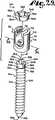
図1、図4、及び図7によく分かるように示しているが、軸部4は細長く、捕捉構造8に隣接している頚部26付近から本体6の先端28まで伸張すると共にそこから半径方向外向きに伸張している、螺旋状に巻かれた骨植え込み可能ねじ部24を有する軸部4の本体6を備えている。使用時、本体6は、把持及び前進用のねじ部24を使用し、先端28を先にして椎骨15に植え込まれるが、図11に示し、後段で更に詳しく説明するように、装着又はねじ回し用工具31で椎骨15の中へとねじ込まれ、頚部26付近まで椎骨15に植え込まれる。軸部4は、全体を符号Aで識別している細長い回転軸を有している。なお、頂部、底部、上方、下方、などの用語は、本出願では、各図面に示される整列、並びにその様な装置に適用される典型的な含意を指すが、アッセンブリ1の実際の使用時の配置を制限するものではないことを指摘しておく。 1, 4 and 7, the
頚部26は、軸部4の本体6から、軸方向外向き且つ上向きに伸張している。頚部26は、ねじ部24が終わっている本体6の隣接する上端又は頂部32と比較して、半径が僅かに小さくなっているのが望ましい。また、頚部26から軸方向外向きに、捕捉構造8が伸張しており、この捕捉構造8は、上端32から一定の距離だけ離して配置され、而して、本体6が椎骨15に植え込まれると椎骨15から一定の距離だけ離れて配置されることになる、接合又は捕捉装置を提供している。 The
捕捉構造8は、軸部4を頭部10に接続し、軸部4を頭部10内に捕捉するように構成されている。捕捉構造8は、多面体形状部であり、具体的には、前側面40と後側面41とが平行になっている、全体を符号38で示す多面体様の構造をしている。前側面40と後側面41とは、それぞれ逆等脚台形の形状をしている。前側面40と後側面41とは、合同で、且つ軸Aに平行である。前側面40と後側面41とは、その構造38の頂面44に隣接しており、頂面44は、実質的に平坦で、軸Aに対して垂直に配置されている。前側面40と後側面41とは、環状着座面又は棚部45まで伸張しており、この棚部45は、軸Aから半径方向に突き出た実質的に平坦な面であり、頂面44に平行に配置されている。頂面44は、着座面45の外径よりも大きい幅Wを有しており、台形の前側面40と後側面41との間に伸張している頂縁46と47を含んでいる。多面体様の構造38の仕上げは傾斜した側面又は面48と49であり、それぞれ、実質的に形状が矩形で、頂縁46と47それぞれから、環状着座面45に隣接して配置されている底縁50と51まで、内向きに勾配が付いている。傾斜という用語は、ここでは、軸部4の本体6に関して、平行でも垂直でも直角でもない方向又は進路又は位置に傾き又は傾斜しているが、それ以外では、軸Aに関して様々な角度に配置されている、面48と49を記述するのに使用されている。傾斜面48と49は、頂面44から軸Aに向けて、軸部4の本体6の先端28に向かう方向に勾配が付いている。底縁50と51の間の幅W2は、幅Wよりも小さく、更に着座面45の外径よりも小さい。 The capturing
軸部4は、頂面44から端面53まで軸方向に突き出た工具係合構造52を更に含んでいる。工具係合構造52は、図11に示すねじ回し工具31を係合させる働きをする。工具31は、ソケットの形態のねじ回し構造を含んでいる。工具31は、工具係合構造52の周りに嵌り、軸部4の本体6を駆動し同時に椎骨15の中にねじ込むためのソケット兼嵌合突起を形成するように構成されている。具体的に、図1から図16の実施形態では、工具係合構造52は、ねじの切られた軸部4の本体6と同軸の六角形をした伸張頭部の形状をしている。 The
軸部4の端面53は、骨スクリューのアッセンブリ1を、図15に示すように組み立て、軸部4が頭部10に対してどの様な整列状態になったときでも、ロッド21と積極的に係合するように、各図に示すように曲線(曲面)ドーム形をしているのが望ましい。或る特定の実施形態では、端面53は、滑らかである。本発明の実施に当たっての要件ではないが、端面53には、端面53とロッド21の間の積極的な摩擦係合を更に増すため、刻み目やローレットを施してもよい。 The end face 53 of the
各図に示す軸部4は、軸部4の全長に亘って軸Aに沿って伸張している小さい中央内径部54を有する套管が設けられている。内径部54は、軸部4の先端28の第1円形口56と、ドーム形の端面53の第2円形口58を有している。内径部54は、ねじの切られた本体6と同軸である。内径部54は、軸部4の本体6の装入に先立ち椎骨15に挿入され、軸部4の本体6を椎骨15に挿入する際の案内となる、或る長さのワイヤ(図示せず)を通す軸部4内通路を提供している。 The
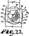
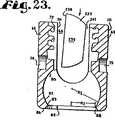
図1及び図5に示すように、頭部10は、部分的に円筒形の内部輪郭と実質的に円筒形の外部輪郭を備えている概ねU字型の外観を有している。頭部10は、一対の直立アーム62、64と一体になった実質的に円筒形の基部60を含んでおり、U字型の受け台を形成すると共に、アーム62と64の間に、上方開口部67と、ロッド21と実質的に同じ半径を有しロッド21を作動的にぴったり受け入れる働きをする下側着座部68と、を備えているU字型の溝66を画定している。 As shown in FIGS. 1 and 5, the
アーム62と64は、それぞれ、内部円筒形の輪郭を画定し、部分的な螺旋状に巻かれた案内及び前進構造72を含んでいる、内側面70を有している。図示の実施形態では、案内及び前進構造72は、下に詳しく説明するように、回転させると、閉鎖構造18側の同様の構造と噛み合うようになっている、部分的な螺旋状に巻かれたフランジ形状をしている。しかしながら、案内及び前進構造62は、代わりに、回転させると閉鎖構造をアーム62とアーム64との間を下向きに作動的に案内し進める働きをする、V字型ねじ、鋸歯ねじ、逆角ねじ、又は他のねじ様又は非ねじ様の螺旋状に巻かれた前進構造であってもよいと予測される。 Each of the
頭部10は、頭部10を軸部4及び保持構造12に、組み付ける際に、保持工具(図示せず)を積極的に係合させて頭部10をしっかりと把持し易くするための、各アーム62と64上に配置された外側の行き止まり把持孔74と75を含んでいる。更に、把持孔74と75は、軸部4の本体6を椎骨15に植え込む際に頭部10を保持するのに使用される。把持孔74と75は、各アーム62と64上の中心に設けられている。しかしながら、把持孔74と75は、アーム62と64の外側面に沿い様々な寸法で様々な位置に設けるようにしてもよいことを指摘しておく。 When the
頭部10のU字型の溝66には、これと連通して、基部60の内側面80によって実質的に画定されている室又はキャビティ78が設けられている。キャビティ78は上向きにU字型の溝66内に開口している。内側面80は、実質的に球形で、その少なくとも一部は、第1半径R1を有する部分的内側球形の着座面82を形成しており、この着座面82は、下で詳しく説明するように、保持構造12と嵌合する。 The
基部60は、第2半径R2を有し且つキャビティ78と連通している口部84を部分的に画定している拘束孔、開口、又は頚部83と、基部60の下側外部86と、を更に含んでいる。口部84は、頭部10の回転軸Bと同軸である。頚部83と下側外部86の間には面取り部88が伸張している。頚部83及び付帯する半径R2を有する口部84は、保持構造12の半径寸法(半径R1)よりも小さい寸法形状に作られ、装着時には、下で詳しく説明するように、保持構造12に対し頚部83の位置に拘束部を形成して、保持構造12が頭部10に完全に着座し捕捉構造8と作動的に係合したときに、保持構造12が頭部10のキャビティ78と下側外部86の間から抜けないようにしている。面取り部88は、頭部10が組み付けられるときには、軸部4の角度範囲を拡大する。 The
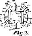
軸部4の捕捉構造8を頭部10内に保持して、軸部4の本体6を頭部10に対して関節運動させるために、二部品構成の保持構造12が使用されている。保持構造12は、図1から図3でよく分かるように、軸部4に付帯する細長い軸Aと同じ作動中心軸を有している。保持構造12は、第1要素又は部品90と、鏡像の第2要素又は部品92を含んでいる。部品90と92は、下で詳しく説明するように、設置されると、頭部10内で捕捉構造8の周りにカラー又はコレットを提供する。 In order to hold the
部品又は第1要素90と第2要素92とは、捕捉構造8と着座面82との両方を滑動可能に且つ密接に把持し、ロッド21と閉鎖構造18又は他の型式の長手方向部材と閉鎖構造とによって軸部4のドーム形の端面53に力が掛けられると、軸部4と頭部10との間に球形の着座面82で、一様で均一的な把持面を提供する。 The part or
ここでは二要素構成の保持構造12を示しているが、保持構造12は、それぞれ捕捉構造8と頭部10の着座面82との両方に滑動可能に摩擦的に噛み合うことができる、複数の要素から構成されていてもよいと予測される。各要素90、92は、寸法がまちまちで、必ずしも互いに鏡像関係になくてもよい。また、図示の実施形態は、部品90と92が、頭部10に完全に装着され軸部4の捕捉構造8に接触したときに、互いに接触しているように示しているが、部品90と92は、頭部10内に捕捉構造8と共に完全に装着されたときに、互いに離間した関係に配置される寸法形状に作られていてもよいと予測される。 Although a two-
各保持部品(第1及び第2要素)90と92は、それぞれ実質的に球形の外側面94と95を含んでおり、各外側面94、95は、頭部10の着座面82の半径R1と実質的に一致する半径を有している。部品90と92は、それぞれの平坦な頂面97と98、及びそれぞれの平坦な底面100と101を含んでいる。頂面97と底面100は平行である。頂面98と底面101も平行である。底面100と101は、図10に示すように頭部10に完全に装着されると、軸部4の環状の着座面45上に当接して着座し、頂面97と98が捕捉構造8の頂面44と平行且つ実質的に面一に配置される。 Each retaining part (first and second elements) 90 and 92 includes a substantially spherical
特に図2に示すように、保持構造12の部品90と92は、それぞれ、上又は下から見ると、各頂面97と98から各底面100と101までの空白部又は貫通路103と104それぞれを取り巻いて形成された、方形に切り欠かれたU字型形状又はC字型形状を有している。各貫通路103と104は、部分的には、角度が付いた又は勾配が付いた面106と107それぞれにより画定されている。面106は、頂縁110と底縁111とを有している。面107は、頂縁112と底縁113とを有している。保持構造12の部品90と92が、実質的に球形の面94と95を、球形の着座面82と摩擦接触させ、底面100と101を、軸部4の環状着座面45に着座させた状態で、頭部10内に作動的に配置されると、面106と107は、それぞれ底面100と101に対する傾斜の度合いが、捕捉構造8の側面48と49の、着座面45に対する傾斜の度合いに対応又は一致する配置になる。これにより、面106と面48の間には実質的に完全な摩擦接触が作り出され、面107と面49の間には実質的に完全な摩擦接触が作り出される。 In particular, as shown in FIG. 2, the
保持構造12の部品90は、更に、頂面97と底面100とのそれぞれに対して垂直に配置された平行な内壁116と117も含んでいる。保持構造12の部品92は、頂面98と底面101とのそれぞれに対して垂直に配置された平行な内壁119と120を含んでいる。内壁116と119は、勾配の付いた面106が側面48と接すると、捕捉構造8の台形の後側面41と摩擦嵌合するように作られており、内壁117と120は、勾配の付いた面107が側面49と接すると、捕捉構造8の台形の前側面40に摩擦嵌合するように作られている。 The
部品90と92とは、互いに鏡像関係にあるので、勾配の付いた面106が側面49と接触し、勾配の付いた面107が側面48と接触し、且つ内壁116と119とが前側面40と、内壁117と120とが後側面41と、それぞれ相手を代えて嵌り合った場合でも、保持構造12は等しく良好に機能することに注目されたい。図示の壁面106、107、117、119、及び120は、滑らか平坦であるが、上記各面は、粗され又は研削されて、捕捉構造8との摩擦接触を強化してもよいと予測される。追加的又は代替的に、捕捉構造8の面40、41、48、及び49は、粗し又は何らかの方法で研削して、保持構造12との摩擦接触を強化してもよい。更に、頭部10の実質的に球形の着座面82と接触する保持構造12の外側面94と95も、ローレット面のような高摩擦面であってもよい。 Since
保持構造12の部品又は第1要素90は、更に、外側面94から内壁116と117までそれぞれ伸張している端壁122と123も含んでいる。端壁122と123は、頂面97に実質的に垂直に配置されている。端壁122は、頂部の面取り部126を含んでおり、端壁123は、頂部の面取り部127を含んでいる。保持構造12の部品92は、更に、外側面95から内壁119と120までそれぞれ伸張している端壁130と131も含んでいる。端壁130と131は、頂面98に対して実質的に垂直に配置されている。端壁130は、頂部の面取り部134を含んでおり、端壁131は、頂部の面取り部135を含んでいる。保持構造12の部品90と92は、実質的に球形の面94と95を、球形の着座面82に滑動可能に摩擦接触させ、底面100と101を軸部4の環状着座面45に着座させた状態で、頭部10内に作動的に配置されると、端壁122と123が、図13に示すように、各端壁130と131に接触するように作られている。面取り部126、127、134、及び135は、保持構造90と92を、頭部10内で捕捉構造8の周りに、ここで引き続いて説明する本発明による方法で装着するための、隙間空間を提供している。更に、本発明によれば、装着時の追加的な隙間を提供するために、部品90と92は、骨スクリューの頭部10に完全に装着されると、端壁122と123が各端壁130と131に対して間隔を置いた実質的に平行な関係に配置されるように、作られてもよいと予測される。 The component or
アッセンブリ1と共に使用される細長いロッド又は長手方向部材21は、脊椎再建術に使用される各種移植片の何れであってもよいが、普通は、一様な直径の実質的に滑らかな円筒形の面136を有する、円筒形の細長い構造体である。ロッド21は、頭部10のU字型の溝66の底部付近にぴったりと着座する寸法形状に作られているのが望ましく、通常の作動時は、溝66の底部の僅かに上方、下側着座面68に配置される。具体的には、ロッド21は、普通は図12に示すように、軸部4の頂部の端面53と直接又は当接係合し、ドーム形の端面53に押し付けるように付勢されるので、必然的に、アッセンブリ1が完全に組み立てられると、軸部4を下向きに頭部10の基部60に向かう方向に付勢する。これを起こさせるため、軸部4の頂部の端面53は、保持構造12が頭部10のキャビティ78の下部で軸部4上にぴったりと着座したとき、少なくとも僅かに溝66の空間内に伸張していなければならない。軸部4と保持構造12は、ロッド21が軸部4の頂部の端面53を下向きに強く押すことにより、頭部10に対し所定の位置に係止又は保持される。しかしながら、本発明による他の実施形態では、上から又は横から装入可能な差込みを、ロッド21と、頂部の端面53及び協働要素(第1及び第2要素)90及び92と、の間に配置することが予測され、その場合、差込みは、初めに頂面53と係合し、そして各要素90及び92の一方又は両方と係合可能である。このような実施形態では、軸部4の頂部の端面53は、溝66の空間の中まで伸張する必要はない。この様な差込みは、ラチェット又は捩って係止させるシステムの様な各種機構を活用して、骨スクリューの頭部10に装着され、ロッド21の挿入に先立ち、骨スクリューの軸部4を頭部10に対して正しい位置に設定するのに使用される。ロッド21が骨スクリューの頭部10に設置された後、差込みは、ロッド21と頂面53の両方に係合して、骨スクリューの軸部4を所望の位置に固定することになる。 The elongate rod or
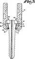
図12、及び図14から図16に示すように、閉鎖構造又は閉鎖蓋18は、直立アーム62と64上の適した噛み合い構造を備えている本発明と共に使用する場合、多種多様な閉鎖構造の何れであってもよい。閉鎖蓋18は、間隔を空けて配置されているアーム53と54の間にねじ込まれる。 As shown in FIGS. 12 and 14-16, the closure structure or
図示の閉鎖蓋18は、ロッド21を擦るかロッド21に食い込ませるための下尖部又は突起139を備えた概ね円筒形状の基部138と、上向きに伸張している破断頭部140と、を有している。基部138は、螺旋状に巻かれた案内及び前進構造141を含んでおり、この前進構造141は、アーム62と64側の案内及び前進構造72と係合させ、時計回りに回転させると、閉鎖構造18を回転させながら頭部10内に進ませることができ、そして、特に、U字型の溝66の頂部又は上向きに開口している部分を覆って、望ましくはアーム62と64を広げることなく、ロッド21を捕捉することのできる寸法形状に作られ配置されている。閉鎖構造18は、更に、トルクが掛けられると前進してロッド21に圧力を掛けてロッド21を作動的に付勢するので、ロッド21は、溝66内に伸張している軸部4の頂端面53に下向きに押し付けられる。軸部4の頂端面53が下向きに付勢されると、ロッド21と頂端面53の間に摩擦係合が作動的に作り出されると共に、保持構造12が頭部10の基部60に向けて押し付けられるので、保持構造12の外側球形面94と95が、頭部10の部分的内側球形の着座面82に摩擦により着座して固定的に押し付けられると共に、軸部4と保持構造12が、頭部10に対して選択された堅固な位置に固定される。 The illustrated
閉鎖構造18の破断頭部140は、基部138に頚部144で固定されていおり、この頚部114は、保持構造12を頭部10に正しく着座させるように設計されている事前に選択されたトルクが掛かると破断分離する寸法形状に作られている。破断頭部140は、ねじ回し兼操作工具147を作動的に受けるための中央の内径部145及び溝146を含んでおり、工具147には、内径部145に入り込む突起148と、溝146に入り込むストッパ149と、を有している。破断頭部140は、更に、トルク印加工具152の従来の嵌合ソケット型の頭部を受け入れて、閉鎖構造18を回転させトルクを加えることができる寸法形状に作られた、外側切子面150を含んでいる。図14及び図16に示すように、反トルク工具153も提供されており、この反トルク工具153は、頭部10の周りに伸張してロッド21と係合し、トルク印加工具152が回転している間、装置1を静止状態に保持する。 The breaking
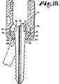
閉鎖構造18は、取り外し工具係合構造も含んでおり、これは、本実施形態では、図16に示すように、基部138に配置された六角形の軸方向に整列した孔154の形をしている。六角の孔154は、破断頭部140が基部138から破断分離された後に、アクセス可能である。孔154は、螺旋状に巻かれた案内及び前進構造141と同軸で、必要に応じて、装着した後で閉鎖構造18の基部138を回転させて取り外すため、アレンレンチ型の六角工具を孔154に差し込めるように設計されている。図には六角形状の孔154を示しているが、工具係合構造は、様々な工具係合形態を取ることができ、一対の離間して配置された孔、左ねじの切られた穴、取り外し容易係合可能段式穴など、の様な各種形状の複数の孔を含んでいてもよい。 The
多軸骨スクリューのアッセンブリ1が、本発明による使用に際して設置される前に、保持構造12の第1要素90と第2要素92とは、通常、図5に示すように先ずU字型の溝66に挿入され又は上から装入され、次いで、キャビティ78に入れられ、保持構造12を頭部10の内側面80に隣接して配置する。代わりのやり方では、図6に示すように、一方の保持構造12の第1要素90は、溝66に挿入又は上方装入され、他方の保持構造12の第2要素92は、口部84を通してキャビティ78の中に挿入又は下方装入される。また代わりのやり方では、第1要素90及び第2要素92の両方は、口部84(図示せず)を通して上向きに装入される。 Before the polyaxial
図7に示すように、保持構造12の要素90及び92が、キャビティ78内に配置された後、軸部4は、矢印160で示すように口部84を通して、頭部10の中に挿入され又は上向きに装入される。図8に示すように、台形の捕捉構造8の頂縁46と47は、各保持構造90と92の勾配の付いた内側面106と107に接触する。最初は、3つの構成要素、即ち捕捉構造8と要素90と92は、全て図8の矢印160で示すように上向きに動かされる。図9に示すように、捕捉構造8が矢印160で示すように引き続き上向きに動いてキャビティ78に入る際に、保持構造12の要素90と92は、頂縁46と47の周りに回転して、矢印162及び163で示すように、基部60に向けて下向きに動き始める。 After the
図10に示すように、各要素90と92は、底面100と101が軸部4の環状着座面45に当接してその上に着座するまで、下向きに動き続ける。一旦、環状着座面45に着座すると、保持構造12の勾配が付いた面106は、捕捉構造8の側面48と摩擦係合し、勾配の付いた保持構造12の面107は、捕捉構造の側面49と摩擦係合する。 As shown in FIG. 10, each
次に、図10の矢印166で示すように、軸部4並びに摩擦係合している保持構造12の各要素90と92を僅かに下向きに動かすと、軸部/保持構造アッセンブリは、保持構造12の面94及び95が、頭部10の着座面82と滑動的に係合した状態で、頭部10のキャビティ78に着座する。保持構造12は、これで頭部10内に完全に着座し、軸部4の捕捉構造8と同軸に整列する。図10に仮想線で示した軸部6に関して、この時点で、捕捉構造8、保持構造12、頭部10の着座面82、及び下側の穴又は頚部83は、協働して、軸部4の本体6を頭部10と回転可能な関係に維持する。図1から図16に示す本発明の実施形態によれば、保持構造12のみが頭部球形の着座面82と滑動可能な係合状態にある。捕捉構造8と軸部4の本体6のねじが切られた部分の両方は、頭部10と間隔を置いて配置された関係にある。回転範囲を図10に示しており、本図は、軸部4の本体6は、頭部10に対して左右及び前後方向の何れにも実質的に角度方向の回転を介して回転させることができるので、実質的には、回転の角度が軸部4の本体6の頚部26と頭部10の拘束頚部83との係合のみで拘束される、自在継ぎ手又はボールジョイントを提供していることを示している。 Next, as shown by arrow 166 in FIG. 10, when the
次に、図11に示すように、アッセンブリ1は、通常は、ねじ回し工具31を使用し、これを軸部4の六角形の伸張部又は工具係合頭部52に係合させ、軸部4を作動的に駆動及び回転させて、軸部4を回しながら椎骨15の様な骨にねじ込まれる。ねじ回し工具31が頭部52に係合する際、その端部が、捕捉構造8の頂面44に当接して摩擦係合するのが望ましい。 Next, as shown in FIG. 11, the
通常、頭部10と保持構造12は、軸部4の本体6を椎骨15に植え込む前に軸部4に組み付けられる。更に、椎骨15は、骨に掛かる応力を最小限にするために事前に穿孔を施して、椎骨15に対する軸部4の設置と角度決めの案内を提供するためにガイドワイヤ(図示せず)を挿入するようにしてもよい。また、ガイドワイヤを案内にしてタップを使用し、タップ孔を形成してもよい。次いで、アッセンブリ1は、先ずワイヤを底部開口部56に通し、次いで、套管の内径部54の頂部の開口部58から出すことにより、ガイドワイヤに外挿される。次いで、ワイヤを設置用案内として用いて、軸部4を椎骨15内にねじ込む。 Usually, the
図12及び図14から図16に示すように、ロッド21は、最終的に、頭部10のU字型の溝66内に配置され、次いで、閉鎖構造又は蓋18がアーム62と64の間に挿入され、ねじ回し兼操作工具147でアーム62、64の間を進められて、ロッド21を押し付けるように付勢又は押圧される。次に、反トルク工具153が、図13及び図14に示すように、頭部10とロッド21の周りの所定の位置に配置され、トルク印加工具又はドライバ152が破断頭部140周りに挿入される。次いで、破断頭部140を、トルクドライバ152を使用しながら事前に選択されたトルク、例えば90から120インチポンドまで捩って、ロッド21を下向きに押して最終的な所望位置に置く。 12 and 14-16, the
軸部4の頂部の頂端面53は、軸部4と頭部10の間の回転角度がどの様な角度でも、概ね同じ量だけ略等しく上向きに溝66内に伸張するように丸みが付けられており、且つ頂端面53は、U字型の溝66内に上向きに伸張する寸法に作られているので、閉鎖構造18をロッド21に向けて下向きに付勢して押し付けると、頂端面53にロッド21が係合し、頂端面53は頭部10の基部60に向けて下向きに押される。軸部4に働く下向きの圧力は、今度は、保持構造12の要素90と92を、下向きに半径方向外向きに頭部10の着座面82に向けて押し付けるので、保持構造12の外側の実質的に球形の面94と95が頭部10の着座面82と摩擦係合する。捕捉構造8の逆向きに傾斜した側面48と49により、要素90と92に掛かる半径方向外向きの力は、要素90と92を頭部10のキャビティ78内に保持する働きもする。閉鎖構造18がロッド21を押圧すると、ロッド21は、一体の捕捉構造8と軸部4の本体6、更には、この時点では捕捉構造8と摩擦係合して捕捉構造8の台形構造38と頭部10の間に配置され又は挟まれている保持構造12の要素90と92を押圧する。保持構造12の要素90と92の位置並びに構成により、軸部4は、頭部10に摩擦的に堅固に取り付けられた状態となり、軸部4の本体6が頭部10及びロッド21に対して所望の角度配置で固定されることになる。 The
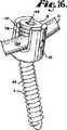
図16は、多軸骨スクリューのアッセンブリ1をロッド21と閉鎖構造18も含めて示している。骨用の軸部4の軸Aは、頭部10の軸Bと同軸ではなく、角度が係止された形で軸部4が固定されている状態を示している。ロッド21などの位置決めに起因して設置処置時に必要に応じて、他の角度配置とすることもできる。 FIG. 16 shows the polyaxial
アッセンブリ1及び付帯するロッド21、並びに閉鎖構造18の取り外しが必要な場合には、アレンレンチ型(図示せず)のねじ回し工具を使って孔154に噛み合わせ、レンチを反時計回りに回し、基部138を回転させて頭部10内で逆方向に進ませることにより分解する。そこで、アッセンブリ1の分解は、組み立てる場合に関して先に説明した手順と逆の順序で行う。 When it is necessary to remove the
図17から図28には、本発明による多軸骨スクリュー装置又はアッセンブリの第2の又は代わりの実施形態を全体として符号201で示している。このアッセンブリ201は、接合型伸縮式二部品又は二要素構成の保持構造212を含んでいる。アッセンブリ201は、先にここで説明した、本発明による装置の第1の実施形態による軸部4と頭部10とを更に含んでいる。従って、軸部4と頭部10とに関してここで既に識別されている符号の全ては、図17から図26に組み込まれ、その記述はここでアッセンブリ201に関して参考文献として援用する。 17 to 28, a second or alternative embodiment of a polyaxial bone screw device or assembly according to the present invention is indicated generally at 201. FIG. The assembly 201 includes a joining structure telescopic two-part or two-element holding structure 212. The assembly 201 further comprises a
先にここで説明した第1の実施形態と同じように、軸部4、頭部10、及び保持構造212は、軸部4の本体6を椎骨15に植え込む前に、組み立てられるのが望ましく、その植え込み手順は、図11に示すようにここで先に説明している。更に、図12及び図14から図16に示す閉鎖構造18、並びにロッド21、及び随意的にロッド21の下方に配置される差込みは、アッセンブリ201と共に使用することができ、その場合もここで先に説明したものと同じ機能と便益が得られる。 As in the first embodiment previously described herein, the
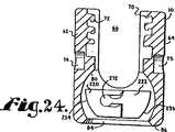
二部品構成の接合型滑動可能伸縮式の脱着可能な保持構造212は、軸部4の捕捉構造8を頭部10内に保持すると共に、軸部4の本体6を頭部10に対して関節運動させるために使用されている。保持構造212は、図17から図21でよく分かるように、軸部4に付帯する細長い軸Aと同じ作動中心軸を有している。保持構造212は、第1要素又は部品220と、実質的に鏡像関係の第2要素又は部品222を含んでいるが、部品220には、第1及び第2の狭い溝224と225が形成されており、部品222は、前記溝224と225それぞれと協働する第1及び第2の伸張部228と229を含んでいる点だけが相違する。伸張部228と229及び協働相手の溝224と225は、それぞれ、保持構造212が内向きに縮み、又は僅かに潰れて楕円の様な形状になり、頭部10の溝66又は口部84何れかの拘束された空間に嵌め込むことができるようにして、保持構造212の頭部10への上方又は下方装入の何れかが行えるようにしている。保持構造212が頭部10のキャビティ78内に配置された後、部品220と222は、伸張部228と229の一部が溝224と225それぞれに配置された状態で外向きに伸ばされ、保持構造212は、捕捉構造8の周りに、捕捉構造8に摩擦的に取り付けられ、同時に、装着されると、頭部10の着座面82にも完全に着座して摩擦的に取り付けられる、カラー又はコレットを提供する。下で詳しく説明するように、部品又は要素220と222は、捕捉構造8と着座面82の両方を滑動可能に且つ密接に把持して、ロッド21と閉鎖構造18又は他の型式の長手方向部材と閉鎖構造とにより軸部4のドーム形の頂端面53に力が掛けられると、軸部4と頭部10の間に球形の着座面82で一様且つ均一的な把持面を提供する。 The two-part joint type slidable telescopic detachable holding structure 212 holds the trapping
各保持構造212の部品220と222は、実質的に球形の外側面234と235をそれぞれ含んでおり、各外側面234と235は、頭部10の着座面82の半径R1と実質的に一致する半径を有している。部品220と222は、各々平坦な頂面237と238、及び各々平坦な底面240と241を更に含んでいる。頂面237と底面240とは、実質的に平行である。頂面238と底面241とは、実質的に平行である。底面240と241は、図28に示すように頭部10内に完全に装着されると、軸部4の環状の着座面45上に当接して着座し、頂面237と238は、捕捉構造8の面44と平行且つ実質的に面一に配置される。 The
特に図17及び図21に示すように、保持構造212の部品220と222は、それぞれ、上又は下から見ると、各頂面237と238から各底面240と241までの開口した貫通路243を取り巻いて形成された、方形に切り欠かれたU字型形状又はC字型形状を有している。貫通路243は、部分的には、部品220と222上に配置された傾斜した又は勾配が付いた面246と247によって画定されている。面246は、頂縁250と底縁251とを有している。面247は、頂縁252と底縁253とを有している。保持構造212の部品220と222とが、実質的に球形の面234と235を球形の着座面82と摩擦接触させ、底面240と241を軸部4の環状着座面45に着座させた状態で、頭部10内に作動的に配置されると、面246と247は、底面240と241それぞれに対する傾斜の度合いが、捕捉構造8の側面48と49の、着座面45に対する傾斜の度合いに対応又は一致する配置になるので、面246と面48の間には実質的に完全な摩擦接触が作り出され、面247と面49の間にも実質的に完全な摩擦接触が作り出される。 In particular, as shown in FIGS. 17 and 21, the
保持構造212の部品220は、更に、頂面237と底面240に対して垂直に配置された、平行な内壁256と257も含んでいる。保持構造の212の部品222は、頂面238と底面241とに対して垂直に配置された、平行な内壁259と260を含んでいる。内壁256と259は、勾配の付いた面246が側面48と接すると、捕捉構造8の台形の後側面41と摩擦嵌合するように作られており、内壁257と260は、勾配の付いた面247が側面49と接すると、捕捉構造8の台形の前側面40と摩擦嵌合するように作られている。 The
部品220と222は、互いに実質的に鏡像関係にあるので、勾配の付いた面246が側面49と接触し、勾配の付いた面247が側面48と接触し、且つ壁256と259が前側面40と、内壁257と260が後側面41と、それぞれ相手を代えて嵌り合った場合でも、保持構造212は等しく良好に機能することを指摘しておく。図示の壁面246、247、256、257、259、及び260は、滑らかで平坦であるが、上記各面は、粗され又は研削されて、捕捉構造8との摩擦接触を強化してもよいと予測される。追加的又は代替的に、捕捉構造8の面40、41、48、及び49は、粗し又は何らかの方法で研削して、接合型の保持構造212との摩擦接触を強化してもよい。更に、頭部10の実質的に球形の着座面82と接触する保持構造212の外側面234と235も、ローレット面のような高摩擦面であってもよい。 Since
保持構造212の部品又は要素220は、外側面234と内壁256及び257とによりそれぞれ境界が規定された下端壁262と263を更に含んでいる。端壁262と263は、頂面237と実質的に垂直に配置されている。保持構造212の部品222は、外側面235及び内壁259と260によりそれぞれ境界が規定された下端壁266と267を更に含んでいる。端壁266と267は、頂面238と実質的に垂直に配置されている。 The component or
部品220に形成されている溝224と225は、それぞれ端壁262と263に開口している。溝224と225は細長く、頂面237と実質的に平行に伸張している。溝224と225は、継ぎ手伸張部228と229をそれぞれ滑動可能に受け入れることができるように作られている。更に、溝224と225は、それぞれ、部分的には、上側面268と下側面269で画定されている。上側面268は、側面又は端面270で終わっており、下側面269は、上向きに突き出たリップ271で終わっている。伸張部228と229は、それぞれ、細長く、ノブ様の突起272を端部に含んでいる。ノブ様の突起272は、各溝224と225に入り込むように作られており、挿入時には、上側面268と下側面269を接続しているU字型の面273に押し付けられるように当接する。図19、図20、及び図25に示すように、下側リップ271は、端壁262と263で終わっており、上記各端面は、リップ271から各底部240と241まで伸張している。ノブ様の突起272が溝224と225に差し込まれた後、伸張部228と229に隣接している突起272の下側部分274は、リップ271に当接することができ、リップ271は、部分的には、突起272を溝224と225内の所定の位置に収容している。リップ272は、更に、下で詳しく説明するように、捕捉構造8が頭部10に挿入される際、保持構造212の要素222が、保持構造212の要素220に対して回転運動する場合の旋回点としても機能し、その様な回転は、継ぎ手の伸張部228と229の頂面が保持構造212の要素220の上端面270に押し付けられるように当接することで制限される。 Grooves 224 and 225 formed in the
溝224と225は、それぞれ或る深さを有しており、保持構造212の部品220と222を、端壁262と266が当接し端壁263と267が当接するまで互いに滑動させると、下で詳しく説明するように、保持構造212を頭部10の中に下向き又は上向きに装入するための図18及び図19に示す幅の狭くなった楕円形の保持構造212を作り出せるようになっている。また、保持構造212の部品220と222は、実質的に球形の面234と235が球形の着座面82と滑動的に摩擦接触し、且つ底面240と241が軸部4の環状の着座面45に着座した状態で、頭部10内に作動的に配置されると、各端壁262と263が、図20及び図21に示すように各端壁266と267に対して、間隔を空けて実質的に平行な関係に配置され、継ぎ手の伸張部228と229が、各溝224と225の中に部分的に配置された状態になるように作られている。 The grooves 224 and 225 each have a certain depth, and when the
多軸骨スクリューのアッセンブリ201が本発明による使用に際して設置される前に、保持構造の要素220と222は、ノブ様の突起272を溝224と225に挿入し、次いで、突起272を溝224と225の中に、保持構造212の要素222が保持構造212の要素220に押し付けられるように当接するまで滑り込ませることにより、組み立てられる。接合された部品220と222は、その後、図23に示すように頭部のU字型の溝66の中に挿入され又は上から装入され、保持構造212の長円部又は最大幅部分が図23に示すように垂直に配置されるように回転される。保持構造212は、次いで、図24に示すように回転させてキャビティ78に挿入され、保持構造212は、頭部10の内側面80に隣接して配置される。代わりに、接合された当接の要素220と222は、口部84(図示せず)を通して上向きに装入してもよい。 Before the polyaxial bone screw assembly 201 is installed for use in accordance with the present invention, the retaining
図25に示すように、保持構造212がキャビティ78内に配置された後、要素220と222は、外向き半径方向に伸ばされ又は引き離され、軸部4が、矢印275で示す方向に口部84を通して頭部10の中に挿入され又は上向きに装入される。図26に示すように、台形の捕捉構造8の頂縁46と47は、各保持構造212の要素220と222の勾配の付いた内側面246と247に接触する。最初、3つの構成要素、即ち捕捉構造8と要素220と要素222とは、全て矢印175で示すように上向きに動かされ、保持構造212を図26の矢印278と279で示す方向に回転させ又はヒンジ旋回させる。図27では、捕捉構造8が、矢印275で示すようにキャビティ78の中へと上向きに動き続けるにつれ、保持構造212は、縁部46と47の回りにヒンジ旋回し又は回転して、矢印282と283で示すように、基部60に向けて下向きに動き始める。ヒンジ旋回又は接合された要素220と222は、底面240と241が軸部4の環状着座面45に当接してその上に着座するまで、下向きに半径方向に動き続ける。図28では、環状着座面45の上に着座して、保持構造212の勾配が付いた面246は、捕捉構造の側面48と摩擦係合し、勾配が付いた保持構造の面247は、捕捉構造8の側面49と摩擦係合している。 After the retaining structure 212 is placed in the
次いで、軸部4並びに摩擦係合している保持構造212を僅かに下向きに動かすのが、軸部/保持構造アッセンブリを頭部10のキャビティ78内に完全に着座させ、保持構造212の面234と235を、頭部10の着座面82と滑動係合させる上で望ましい。保持構造212は、この時点で頭部10内に完全に着座し、軸部4の捕捉構造8と同軸に整列している。この時点で、捕捉構造8、保持構造212、頭部10の着座面82、及び下側の穴又は頚部83は、協働して、軸部4の本体6を頭部10と回転可能な関係に維持する。図17から図28に示す本発明の実施形態によれば、保持構造212だけが頭部10の球形の着座面82と滑動可能な係合状態にある。捕捉構造8と軸部4の本体6のねじが切られた部分は、共に、頭部10と間隔を空けて配置された関係にある。アッセンブリ1に関して図10に示したものと同様の回転範囲が、本発明のアッセンブリ201でも可能である。軸部4の本体6は、頭部10に対して左右及び前後方向の何れにも実質的に角度方向の回転を介して回転させることができるので、実質的には、回転の角度が軸部4の本体6の頚部26と頭部10の拘束頚部83との係合のみで拘束される、自在継ぎ手又はボールジョイントを提供している。 Moving the
アッセンブリ1に関してここで先に説明した図12及び図14から図16に示すように、アッセンブリ201は、同様に、ねじ回し工具31を使用し、これを軸部4の六角形の伸張部又は工具係合頭部52に係合させ、軸部4を作動的に駆動及び回転させて、軸部4を回すことにより、椎骨15の様な骨にねじ込まれる。ねじ回し工具31が工具係合頭部52に係合させる際、その端部が、捕捉構造8の頂面44に当接して摩擦係合するのが望ましい。 As previously described herein with respect to
通常、頭部10と保持構造212は、軸部4の本体6を椎骨15に植え込む前に軸部4に組み付けられる。アッセンブリ1に関してここで説明している、骨スクリューの挿入に備えて椎骨15に前処理を施す各段階、骨スクリューの植え込み工程、ロッド整復及び閉鎖蓋設置工程、及び閉鎖蓋取り外し工程は、アッセンブリ201についても行うことができる。このような各工程並び上で説明したアッセンブリ1の装置を、ここでアッセンブリ201に関する参考資料として援用する。 Usually, the
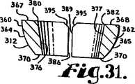
図29から図36では、本発明による多軸骨スクリュー装置又はアッセンブリの第3の実施形態を全体として符号301で表している。アッセンブリ301は、上向きに伸張している実質的に円錐形の捕捉構造308と一体の本体306を更に含んでいる軸部304と、円錐形の捕捉構造308と協働するように作られた二要素又は二部品構成の保持構造312を含んでいる。アッセンブリは、更に、先にここで説明した第1のアッセンブリ1の頭部10も含んでいる。従って、頭部10に関して先に特定した符号の全てを、図29から図36に組み込み、その記述を、ここでアッセンブリ301に関する参考資料として援用する。 In FIGS. 29 to 36, a third embodiment of a polyaxial bone screw device or assembly according to the present invention is generally designated 301. The
軸部304、頭部10、及び保持構造312は、軸部304の本体306を、図11に示している椎骨15と同様の椎骨(図示せず)に植え込む前に組み立てるのが望ましく、その手順は、アッセンブリ1及び図12に関してここで説明済みである。更に、図12及び図14から図16に示している閉鎖構造18、並びにそこで示しているロッド21も、アッセンブリ1に関して説明したように、アッセンブリ301と共に利用することができ、その説明を、ここでアッセンブリ301に関する参考資料として援用する。ロッド21と係合可能な差込みも、アッセンブリ1に関してここで説明しているように利用することができる。頭部10と軸部304は、それぞれが互いに対して、複数の角度、関節運動、又は回転整列の何れにおいても、且つ、左右、前後、両方向について選択された角度範囲内で、固定できるやり方で協働し、頭部10と軸部304とが、移植処置の終了間際に互いに対して係止又は固定されるまで、両者の柔軟性のある又は関節運動可能な係合ができるようにしている。 The shaft 304,
図29と図33とによく分かるように示しているが、軸部304は細長く、その軸部304の本体306は、捕捉構造308に隣接する頚部326付近から本体306の先端328まで伸張すると共にそこから半径方向外向きに伸張している、螺旋状に巻かれた骨に植え込み可能なねじ部324を有している。使用時、本体306は、把持及び前進用のねじ部324を使用し、先端328を先にして椎骨15に植え込まれるが、図11に示す工具31の様な装着又はねじ回し用工具で椎骨15の中へとねじ込まれ、頚部326付近まで椎骨に植え込まれる。軸部304は、全体を符号A’で識別されている細長い回転軸を有している。 As shown in FIGS. 29 and 33, the shaft 304 is elongated and the
頚部326は、軸部304の本体306から軸方向外向き且つ上向きに伸張している。頚部326は、ねじ部324が終わっている本体306の隣接する上端又は頂部332と比べて、半径が僅かに小さくなっている。また、頚部326から軸方向外向きに、捕捉構造308が伸張しており、この捕捉構造308は、上端332から一定の距離だけ離して配置され、而して、本体306が椎骨15に植え込まれると椎骨15から一定の距離だけ離れて配置されることになる、接合又は捕捉装置を提供している。 The
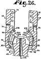
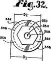
捕捉構造308は、軸部304を頭部10に接続すると共に軸部304を頭部10内に捕捉することができるように作られている。捕捉構造308は、外側の円錐形の表面又は面338を備えた逆円錐形状部である。表面338は、実質的に環状の頂面344と、頚部326に隣接して配置された実質的に環状の着座面又は棚部345の間を伸張している。頂面344と着座面345は、共に実質的に平坦で、軸A’から半径方向に伸張し、軸A’に垂直に配置されている。頂面344は、外側円形縁348を有しており、これは円錐形の面338の外側縁でもある。円錐形の表面338は、下側の円形縁350を有しており、これはまた、着座面345の内側縁を画定している。外側円形縁348は、内側縁340の直径D2よりも大きい直径D1を有している。直径D1は、着座面345の外径よりも大きい。 The
軸部304は、頂面344からドーム形の端面353まで軸方向に突き出た工具係合構造352を更に含んでいる。工具係合構造352は、図11に示すねじ回し工具31を係合させる働きをする。工具31は、ソケットの形をした駆動構造を含んでいる。工具31は、工具係合構造352の周りに嵌り込んで、ソケット及び嵌合突起を形成し、軸部304の本体306を駆動して椎骨15にねじ込むことができるように作られている。具体的には、図29及び図32の実施形態では、工具係合構造352は、ねじが切られた軸部304の本体306と同軸の六角形状の伸張頭部の形状をしている。 The shaft portion 304 further includes a
軸部304の端面353は、骨スクリューのアッセンブリ301を組み立て、軸部304が頭部10に対してどの様な整列状態になったときでも、ロッド21と積極的に係合するように、各図に示すように曲線(曲面)状又はドーム形をしているのが望ましい。或る特定の実施形態では、面353は、滑らかである。本発明の実施に当たっての要件ではないが、面353には、面353とロッド21の間の摩擦係合を更に増すため、刻み目やローレットを施してもよい。 The
各図に示す軸部304は、軸部304の全長に亘って軸A’に沿って伸張している小さい中央の内径部354を有し、カニューレが挿入される。内径部354は、軸部304の先端328の第1円形口356と、ドーム形の面353の第2円形口358と、を有している。内径部354は、ねじの切られた本体306と同軸である。内径部354は、軸部304の本体306の挿入に先立ち椎骨15に挿入され、軸部304の本体306を椎骨15に挿入する際の案内となる、或る長さのワイヤ(図示せず)を通す軸部304内の通路を提供している。 The shaft portion 304 shown in each figure has a small central
二部品又は二要素構成の保持構造312は、軸部304の捕捉構造308を頭部10内で保持すると共に、軸部304の本体306を頭部10に対して関節運動させるのに使用されている。保持構造312は、図29から図31でよく分かるように、軸部304に付帯する細長い軸A’と同じ作動中心軸を有している。保持構造312は、別個の第1要素又は部品360と、別個の鏡像関係にある第2要素又は部品362と、を含んでいる。部品360と362は、下で詳しく説明するように、装着されると、協働して、頭部10内で捕捉構造308の周りに拘束及び関節運動用の不連続なカラー又はコレットを提供する。 A two-part or two-
保持部品又は要素360と362は、捕捉構造308と頭部10の着座面82の両方を滑動可能に且つ密接して把持し、ロッド21と閉鎖構造18又は他の型式の長手方向部材と閉鎖構造とによって軸部304のドーム形の面353に力が掛けられると、軸部304と頭部10の間に球形の着座面82で一様で均一的な把持面を提供する。 The holding parts or
ここでは二要素構成の保持構造312を示しているが、保持構造312は、それぞれ捕捉構造308と頭部10の着座面82の両方と滑動可能に摩擦的に噛み合うことができる、2個から複数個の要素から構成されていてもよいと予測される。各要素は、寸法がまちまちであってもよく、また、必ずしも互いに鏡像関係になくてもよい。 Although a two-
保持構造312の各部品360と362は、実質的に球形の外側面364と365をそれぞれ含んでおり、各外側面364、365は、頭部10の着座面82の半径R1と実質的に一致する半径を有している。部品360と362は、それぞれの平坦な頂面367と368、及びそれぞれの平坦な底面370と371を含んでいる。頂面367と底面370とは、実質的に平行である。頂面368と底面371も実質的に平行である。底面370と371は、図32に示すように頭部10に完全に装着されると、軸部304の環状の着座面345に当接して着座し、頂面367と368は、捕捉構造308の面344と平行且つ実質的に面一に配置される。 Each
特に図30に示すように、保持構造312の部品360と362それぞれは、上又は下から見ると、各頂面367と368から各底面370と371までの空白部又は貫通路373と374それぞれを取り巻いて形成されたC字型形状を有している。各通路373と374は、部分的には、傾斜した又は勾配が付いた内側の円錐形の面376と377それぞれによって画定されている。面376は、半円形の頂縁380と半円形の底縁381とを有している。面377は、半円形の頂縁382と半円形の底縁383とを有している。保持構造312の部品360と362が、実質的に球形の面364と365を球形の着座面82と摩擦接触させ、底面370と371を軸部304の環状着座面345に着座させた状態で、頭部10内に作動的に配置されると、内側の円錐形の面376と377は、底面370と371それぞれに対する傾斜の度合いが、捕捉構造308の円錐形の表面338の、着座面345に対する傾斜の度合いに対応又は一致する配置になるので、面338と面376及び377との両方の間には実質的に完全な摩擦接触が作り出される。 In particular, as shown in FIG. 30, the
図31に示すように、内側の円錐形の面376及び377は、図面には滑らか又は平坦に示されているが、上記各面376、377は、粗し又は研削して、捕捉構造308との摩擦接触を高めるようにしてもよいと予測される。追加的又は代替的に、捕捉構造308の円錐面388は、粗し又は何らかの方法で研削して、保持構造312との摩擦接触を強化してもよい。更に、頭部10の実質的に球形の着座面82と接触する保持構造312の外側面364と365も、ローレット面のような高摩擦面であってもよい。 As shown in FIG. 31, the inner
保持構造312の部品360は、更に、頂面367と底面370それぞれに対して垂直に配置された、平坦な端壁386と387も含んでいる。保持構造312の部品362は、頂面368と底面371それぞれに対して垂直に配置された、平坦な端壁389と390を含んでいる。壁386、387、389、及び390それぞれは、頂部の面取り部396を含んでいる。保持構造312の部品360と362は、実質的に球形の面364と365が球形の着座面82と滑動的に摩擦接触し、底面370と371が軸部304の環状着座面345に着座した状態で、頭部10内に作動的に配置されると、端壁386と387が各端壁389と390に対して間隔を空けて実質的に平行な関係となるように作られているが、互いに接触した状態となるように作られていてもよい。面取り部395は、保持構造312の部品360と362を、頭部10のの中で捕捉構造308の周りに、ここで引き続き説明する本発明の方法によって装着するための隙間空間を提供している。 The
図33に示すように、多軸骨スクリューのアッセンブリ301が本発明による使用に際して設置される前に、保持構造312の要素360と362は、通常は先ず、矢印397で示すように頭部U字型の溝66に挿入され又は上から装入され、次いで、キャビティ78の中に入れられ、保持構造312が頭部10の内側面80に隣接して配置される。代わりのやり方では、一方の保持構造312の要素360は、溝66に挿入され又は上方装入され、他方の保持構造312の要素362は口部84(図示せず)を通してキャビティ78の中に挿入され又は下方装入される。別の代わりのやり方では、要素360と362の両方が、口部84(図示せず)を通して挿入され又は上向きに装入される。 As shown in FIG. 33, before the polyaxial
図33及び図34に示すように、保持構造312の要素360と362がキャビティ78の中に配置された後、軸部304は、口部84を通して頭部10の中に挿入され又は上向きに装入される。捕捉構造308の円錐面338の外側円形縁348は、各保持構造312の要素360と362の勾配が付いた内側面376と377に接触する。最初は、3つの構成要素全て、即ち捕捉構造308と要素360と要素362とは、矢印398で示すように上向きに動く。次いで、軸部304が矢印398で示すように上向きにキャビティ78の中へと動き続けるにつれ、保持構造312の要素360と362が、縁部348回りに回転して、図34及び図35に矢印399と400で示すように、基部60に向けて下向きに且つ捕捉構造308の周りに半径方向に動き始める。 After the
図35に示すように、要素360と362は、底面370と371が、図36に示すように、軸部304の環状着座面345に当接してその上に着座するまで、下向きに動き続ける。一旦、環状着座面345に着座すると、保持構造312の勾配が付いた面376と377は、捕捉構造308の円錐形の面338と摩擦係合する。 As shown in FIG. 35, the
次いで、軸部304を僅かに下向きに動かすのは、保持面(外側面)364と365を頭部10の着座面82と滑動的に係合させて、軸部/保持構造アッセンブリを頭部10のキャビティ78内に完全に着座させる上で望ましい。保持構造312は、これで頭部10内に完全に着座し、軸部304の捕捉構造308と同軸に整列している。この時点で、捕捉構造308、保持構造312、頭部10の着座面82、及び頭部10の拘束頚部83は、協働して、軸部304の本体306を頭部10と回転可能な関係に維持する。保持構造312だけが、頭部10の球形の着座面82と滑動可能に係合している。捕捉構造308と、軸部304の本体306のねじが切られた部分は、共に、頭部10と間隔を置いて配置された関係にある。アッセンブリ1に関して図10に示したものと同様の回転範囲が、本発明のアッセンブリ301でも可能である。軸部304の本体306は、頭部10に対して左右及び前後方向の何れにも実質的に角度方向の回転を介して回転させることができるので、実質的には、回転の角度が軸部304の本体306の頚部326と頭部10の拘束頚部83との係合のみで拘束される、自在継ぎ手又はボールジョイントを提供している。 The shaft 304 is then moved slightly downward by causing the retaining surfaces (outer surfaces) 364 and 365 to slidably engage the seating surface 82 of the
アッセンブリ1に関してここで先に説明した図12及び図14から図16に示すように、アッセンブリ301も同様に、ねじ回し工具31を使用し、これを軸部304の六角形の伸張部又は工具係合頭部352に係合させ、軸部304を作動的に駆動及び回転させて軸部304を回すことにより、椎骨15の様な骨にねじ込まれる。ねじ回し工具31を頭部352に係合させる際、その端部は、捕捉構造308の頂面344に当接して摩擦係合するのが望ましい。 12 and 14-16 previously described herein with respect to the
通常、頭部10と保持構造312は、軸部304の本体306を椎骨15に植え込む前に軸部304に組み付けられる。アッセンブリ1に関してここで説明している、骨スクリューの挿入に備えて椎骨15に前処理を施す各段階、骨スクリューを植え込む工程、ロッド整復及び閉鎖蓋装着工程、及び閉鎖蓋取り外し工程は、アッセンブリ301でも同様に行われる。このような各工程並びに上で説明したアッセンブリ1の装置を、ここでアッセンブリ301に関する参考資料として援用する。 Typically, the
ここでは、本発明の或る特定の形態を例示し説明してきたが、本発明は、説明及び図示した特定の部品の形態又は配置に限定されるものではないものと理解されたい。 Although certain specific forms of the invention have been illustrated and described herein, it should be understood that the invention is not limited to the specific forms or arrangements of parts described and illustrated.
Claims (5)
Translated fromJapanese(a)複数個からなる保持構造の要素を、上部のロッド受入れ溝と下部の軸部受入れの開口部との内の一方を通して、頭部のキャビティ内へ挿入する段階と、
(b)骨スクリューの軸部の捕捉構造を、前記頭部の前記軸部受入れの開口部を通して、前記頭部のキャビティの中に挿入する段階であって、
前記捕捉構造は、ねじの切られた細長い軸部の本体と一体であり、且つ前記本体から間隔を空けて配置された縁部と、前記縁部と前記本体との間に配置された傾斜面と、を有している、前記捕捉構造を頭部のキャビティ内へ挿入する段階と、
(c)前記捕捉構造を前記上部のロッド受入れ溝に向けて動かし、前記保持構造の要素を、前記捕捉構造の周りに、前記下部の軸部受入れの開口部に向けて動かしながら回転させ、前記保持構造の要素の少なくとも一方が前記傾斜面に完全に接触するまで、回転させることにより、前記捕捉構造を、前記キャビティ内で前記保持構造に摩擦係合させる段階と、から成る方法。In the assembly method of the polyaxial bone screw,
(A) inserting a plurality of retaining structure elements into one of the head cavities through one of the upper rod receiving groove and the lower shaft receiving opening;
(B) inserting a bone screw shaft capture structure into the head cavity through the shaft-receiving opening of the head;
The capture structure is integral with a threaded elongated shaft body and spaced from the body, and an inclined surface disposed between the edge and the body. Inserting the capture structure into the cavity of the head, and
(C) moving the capture structure toward the upper rod receiving groove, rotating the retaining structure elements around the capture structure, moving toward the lower shaft receiving opening, Causing the capture structure to frictionally engage the retention structure within the cavity by rotating until at least one of the elements of the retention structure is in full contact with the inclined surface.
前記保持構造の要素は、第1及び第2要素であり、
前記捕捉構造の縁部は第1縁部であり、前記捕捉構造は、第2縁部を含んでおり、
前記方法は、前記保持構造の第1及び第2要素を、同時に前記捕捉構造の第1及び第2縁部周りに回転させる段階を、含んでいる、方法。The method of claim1 , comprising:
The elements of the holding structure are first and second elements;
An edge of the capture structure is a first edge, and the capture structure includes a second edge;
The method includes the step of simultaneously rotating first and second elements of the retaining structure about first and second edges of the capture structure.
(d)前記捕捉構造の上に配置されている工具係合形状部に係合させた工具で前記軸部の本体を回すことにより、前記軸部の本体を骨にねじ込む段階を、更に含んでいる、方法。The method of claim1 , comprising:
(D) further comprising the step of screwing the shaft body into the bone by turning the shaft body with a tool engaged with a tool engagement feature disposed on the capture structure. Is that way.
(e)次いで、ロッドを前記溝に挿入する段階と、
(f)閉鎖構造を前記溝に挿入することにより、前記ロッドを前記捕捉構造に押し付ける段階と、を更に含んでいる、方法。The method of claim3 , comprising:
(E) then inserting a rod into the groove;
And (f) pressing the rod against the capture structure by inserting a closure structure into the groove.
(a)骨スクリューの軸部と、頭部と、複数個からなる別個の要素を有する保持構造と、を用意する段階と、
(b)前記軸部に少なくとも1つの傾斜面を有する上部構造を設ける段階と、
(c)前記頭部に、中央のキャビティと連通しているロッド受入れ溝と、前記キャビティを前記頭部の下側と接続する軸部受入れの開口部と、を設ける段階と、
(d)前記保持構造の各要素を、前記キャビティに装入する段階と、
(e)前記軸部の捕捉構造を、前記軸部受入れ開口部を通して、前記キャビティ内に上方装入する段階と、
(f)前記捕捉構造を前記ロッド受入れ溝に向けて動かしながら、前記保持構造の各要素を前記頭部のキャビティ内で前記軸部の前記上部構造の周りに、前記各要素が傾斜面に接触して、前記接触した傾斜面と前記頭部との間に捕捉されるまで、回転させる段階と、から成る方法。In the assembly method of the polyaxial bone screw,
(A) providing a bone screw shaft, a head, and a holding structure having a plurality of separate elements;
(B) providing an upper structure having at least one inclined surface on the shaft;
(C) providing the head with a rod receiving groove communicating with a central cavity, and a shaft receiving opening for connecting the cavity to a lower side of the head;
(D) charging each element of the holding structure into the cavity;
(E) loading the shaft capturing structure upwardly into the cavity through the shaft receiving opening;
(F) While moving the capture structure toward the rod receiving groove, the elements of the holding structure are brought into contact with the inclined surface around the upper structure of the shaft portion in the cavity of the head. And rotating until trapped between the contact ramp and the head.
Applications Claiming Priority (4)
| Application Number | Priority Date | Filing Date | Title |
|---|---|---|---|
| US63047804P | 2004-11-23 | 2004-11-23 | |
| US60/630,478 | 2004-11-23 | ||
| US11/281,818US7625396B2 (en) | 2004-11-23 | 2005-11-17 | Polyaxial bone screw with multi-part shank retainer |
| PCT/US2005/041504WO2006057874A2 (en) | 2004-11-23 | 2005-11-17 | Polyaxial bone screw with multi-part shank retainer |
Related Child Applications (1)
| Application Number | Title | Priority Date | Filing Date |
|---|---|---|---|
| JP2011108381ADivisionJP2011177534A (en) | 2004-11-23 | 2011-05-13 | Polyaxial bone screw with multi-part shank retainer |
Publications (2)
| Publication Number | Publication Date |
|---|---|
| JP2008520357A JP2008520357A (en) | 2008-06-19 |
| JP4782144B2true JP4782144B2 (en) | 2011-09-28 |
Family
ID=69147297
Family Applications (2)
| Application Number | Title | Priority Date | Filing Date |
|---|---|---|---|
| JP2007543195AExpired - Fee RelatedJP4782144B2 (en) | 2004-11-23 | 2005-11-17 | Multi-axis bone screw with multi-component shaft cage |
| JP2011108381APendingJP2011177534A (en) | 2004-11-23 | 2011-05-13 | Polyaxial bone screw with multi-part shank retainer |
Family Applications After (1)
| Application Number | Title | Priority Date | Filing Date |
|---|---|---|---|
| JP2011108381APendingJP2011177534A (en) | 2004-11-23 | 2011-05-13 | Polyaxial bone screw with multi-part shank retainer |
Country Status (8)
| Country | Link |
|---|---|
| US (2) | US7625396B2 (en) |
| EP (1) | EP1814470B1 (en) |
| JP (2) | JP4782144B2 (en) |
| AT (1) | ATE536821T1 (en) |
| AU (1) | AU2005309869B2 (en) |
| CA (1) | CA2587630C (en) |
| ES (1) | ES2375723T3 (en) |
| WO (2) | WO2006057874A2 (en) |
Families Citing this family (164)
| Publication number | Priority date | Publication date | Assignee | Title |
|---|---|---|---|---|
| US7833250B2 (en) | 2004-11-10 | 2010-11-16 | Jackson Roger P | Polyaxial bone screw with helically wound capture connection |
| US8353932B2 (en)* | 2005-09-30 | 2013-01-15 | Jackson Roger P | Polyaxial bone anchor assembly with one-piece closure, pressure insert and plastic elongate member |
| US8876868B2 (en) | 2002-09-06 | 2014-11-04 | Roger P. Jackson | Helical guide and advancement flange with radially loaded lip |
| US7621918B2 (en) | 2004-11-23 | 2009-11-24 | Jackson Roger P | Spinal fixation tool set and method |
| US6716214B1 (en) | 2003-06-18 | 2004-04-06 | Roger P. Jackson | Polyaxial bone screw with spline capture connection |
| US7377923B2 (en) | 2003-05-22 | 2008-05-27 | Alphatec Spine, Inc. | Variable angle spinal screw assembly |
| US7967850B2 (en) | 2003-06-18 | 2011-06-28 | Jackson Roger P | Polyaxial bone anchor with helical capture connection, insert and dual locking assembly |
| US7766915B2 (en) | 2004-02-27 | 2010-08-03 | Jackson Roger P | Dynamic fixation assemblies with inner core and outer coil-like member |
| US8366753B2 (en) | 2003-06-18 | 2013-02-05 | Jackson Roger P | Polyaxial bone screw assembly with fixed retaining structure |
| JP4357486B2 (en)* | 2003-06-18 | 2009-11-04 | ロジャー・ピー・ジャクソン | Polyaxial bone screw with spline capture connection |
| US8926670B2 (en) | 2003-06-18 | 2015-01-06 | Roger P. Jackson | Polyaxial bone screw assembly |
| US7776067B2 (en) | 2005-05-27 | 2010-08-17 | Jackson Roger P | Polyaxial bone screw with shank articulation pressure insert and method |
| US7527638B2 (en) | 2003-12-16 | 2009-05-05 | Depuy Spine, Inc. | Methods and devices for minimally invasive spinal fixation element placement |
| US8152810B2 (en) | 2004-11-23 | 2012-04-10 | Jackson Roger P | Spinal fixation tool set and method |
| US8475495B2 (en) | 2004-04-08 | 2013-07-02 | Globus Medical | Polyaxial screw |
| US7503924B2 (en) | 2004-04-08 | 2009-03-17 | Globus Medical, Inc. | Polyaxial screw |
| DE202004020396U1 (en) | 2004-08-12 | 2005-07-07 | Columbus Trading-Partners Pos und Brendel GbR (vertretungsberechtigte Gesellschafter Karin Brendel, 95503 Hummeltal und Bohumila Pos, 95445 Bayreuth) | Child seat for motor vehicles |
| US7186255B2 (en)* | 2004-08-12 | 2007-03-06 | Atlas Spine, Inc. | Polyaxial screw |
| US8926672B2 (en) | 2004-11-10 | 2015-01-06 | Roger P. Jackson | Splay control closure for open bone anchor |
| ATE536821T1 (en)* | 2004-11-23 | 2011-12-15 | Roger P Jackson | POLYAXIAL BONE SCREW WITH MULTIPLE SHAFT FIXATION |
| US20130144346A1 (en)* | 2004-11-23 | 2013-06-06 | Roger P. Jackson | Modular polyaxial bone anchor with retainer having interconnected pieces |
| US9980753B2 (en) | 2009-06-15 | 2018-05-29 | Roger P Jackson | pivotal anchor with snap-in-place insert having rotation blocking extensions |
| US9168069B2 (en) | 2009-06-15 | 2015-10-27 | Roger P. Jackson | Polyaxial bone anchor with pop-on shank and winged insert with lower skirt for engaging a friction fit retainer |
| US8308782B2 (en)* | 2004-11-23 | 2012-11-13 | Jackson Roger P | Bone anchors with longitudinal connecting member engaging inserts and closures for fixation and optional angulation |
| US8444681B2 (en) | 2009-06-15 | 2013-05-21 | Roger P. Jackson | Polyaxial bone anchor with pop-on shank, friction fit retainer and winged insert |
| US7875065B2 (en) | 2004-11-23 | 2011-01-25 | Jackson Roger P | Polyaxial bone screw with multi-part shank retainer and pressure insert |
| WO2006058221A2 (en) | 2004-11-24 | 2006-06-01 | Abdou Samy M | Devices and methods for inter-vertebral orthopedic device placement |
| DE102005005647A1 (en)* | 2005-02-08 | 2006-08-17 | Henning Kloss | Pedicle screw for spinal column stabilizing device, has screw head with two opposed oblong hole shaped recesses, and ball unit including recess for accommodating connecting unit and movably mounted in head |
| AU2006214001B2 (en) | 2005-02-18 | 2011-05-26 | Samy Abdou | Devices and methods for dynamic fixation of skeletal structure |
| US12102357B2 (en) | 2005-02-22 | 2024-10-01 | Roger P. Jackson | Pivotal bone anchor assembly with cannulated shank having a planar top surface and method of assembly |
| US7901437B2 (en) | 2007-01-26 | 2011-03-08 | Jackson Roger P | Dynamic stabilization member with molded connection |
| AU2006283126A1 (en)* | 2005-08-24 | 2007-03-01 | Thomson Licensing | Method for graphical scaling of LCDs in mobile television devices |
| US12357348B2 (en) | 2005-09-30 | 2025-07-15 | Roger P. Jackson | Method of assembling a pivotal bone anchor assembly with press-in-place insert |
| US20070118117A1 (en)* | 2005-10-20 | 2007-05-24 | Ebi, L.P. | Bone fixation assembly |
| GB0521582D0 (en) | 2005-10-22 | 2005-11-30 | Depuy Int Ltd | An implant for supporting a spinal column |
| GB0600662D0 (en) | 2006-01-13 | 2006-02-22 | Depuy Int Ltd | Spinal support rod kit |
| US8348952B2 (en) | 2006-01-26 | 2013-01-08 | Depuy International Ltd. | System and method for cooling a spinal correction device comprising a shape memory material for corrective spinal surgery |
| DE602006009069D1 (en)* | 2006-04-06 | 2009-10-22 | Biedermann Motech Gmbh | Angled polyaxial bone anchoring device |
| US20070270807A1 (en)* | 2006-04-10 | 2007-11-22 | Sdgi Holdings, Inc. | Multi-piece circumferential retaining ring |
| US20080015597A1 (en)* | 2006-04-28 | 2008-01-17 | Whipple Dale E | Large diameter bone anchor assembly |
| US8361129B2 (en)* | 2006-04-28 | 2013-01-29 | Depuy Spine, Inc. | Large diameter bone anchor assembly |
| US20080015576A1 (en)* | 2006-04-28 | 2008-01-17 | Whipple Dale E | Large diameter bone anchor assembly |
| US8133262B2 (en) | 2006-04-28 | 2012-03-13 | Depuy Spine, Inc. | Large diameter bone anchor assembly |
| US20080058808A1 (en) | 2006-06-14 | 2008-03-06 | Spartek Medical, Inc. | Implant system and method to treat degenerative disorders of the spine |
| WO2008024373A2 (en)* | 2006-08-21 | 2008-02-28 | Abdou M Samy | Bone screw systems and methods of use |
| US8162990B2 (en)* | 2006-11-16 | 2012-04-24 | Spine Wave, Inc. | Multi-axial spinal fixation system |
| US20080161853A1 (en)* | 2006-12-28 | 2008-07-03 | Depuy Spine, Inc. | Spine stabilization system with dynamic screw |
| US8636783B2 (en)* | 2006-12-29 | 2014-01-28 | Zimmer Spine, Inc. | Spinal stabilization systems and methods |
| WO2008082836A1 (en)* | 2006-12-29 | 2008-07-10 | Abbott Spine Inc. | Spinal stabilization systems and methods |
| AU2008206396A1 (en) | 2007-01-12 | 2008-07-24 | Lanx, Inc. | Bone fastener assembly |
| US8979904B2 (en) | 2007-05-01 | 2015-03-17 | Roger P Jackson | Connecting member with tensioned cord, low profile rigid sleeve and spacer with torsion control |
| US7942909B2 (en)* | 2009-08-13 | 2011-05-17 | Ortho Innovations, Llc | Thread-thru polyaxial pedicle screw system |
| US7942911B2 (en)* | 2007-05-16 | 2011-05-17 | Ortho Innovations, Llc | Polyaxial bone screw |
| US7951173B2 (en) | 2007-05-16 | 2011-05-31 | Ortho Innovations, Llc | Pedicle screw implant system |
| US8197518B2 (en) | 2007-05-16 | 2012-06-12 | Ortho Innovations, Llc | Thread-thru polyaxial pedicle screw system |
| US7942910B2 (en) | 2007-05-16 | 2011-05-17 | Ortho Innovations, Llc | Polyaxial bone screw |
| US7947065B2 (en) | 2008-11-14 | 2011-05-24 | Ortho Innovations, Llc | Locking polyaxial ball and socket fastener |
| US8109970B2 (en) | 2007-06-05 | 2012-02-07 | Spartek Medical, Inc. | Deflection rod system with a deflection contouring shield for a spine implant and method |
| US8114134B2 (en) | 2007-06-05 | 2012-02-14 | Spartek Medical, Inc. | Spinal prosthesis having a three bar linkage for motion preservation and dynamic stabilization of the spine |
| US8048128B2 (en) | 2007-06-05 | 2011-11-01 | Spartek Medical, Inc. | Revision system and method for a dynamic stabilization and motion preservation spinal implantation system and method |
| US8021396B2 (en) | 2007-06-05 | 2011-09-20 | Spartek Medical, Inc. | Configurable dynamic spinal rod and method for dynamic stabilization of the spine |
| US8052722B2 (en) | 2007-06-05 | 2011-11-08 | Spartek Medical, Inc. | Dual deflection rod system for a dynamic stabilization and motion preservation spinal implantation system and method |
| US8092501B2 (en) | 2007-06-05 | 2012-01-10 | Spartek Medical, Inc. | Dynamic spinal rod and method for dynamic stabilization of the spine |
| US8048123B2 (en) | 2007-06-05 | 2011-11-01 | Spartek Medical, Inc. | Spine implant with a deflection rod system and connecting linkages and method |
| US8083772B2 (en) | 2007-06-05 | 2011-12-27 | Spartek Medical, Inc. | Dynamic spinal rod assembly and method for dynamic stabilization of the spine |
| US8048115B2 (en) | 2007-06-05 | 2011-11-01 | Spartek Medical, Inc. | Surgical tool and method for implantation of a dynamic bone anchor |
| US20090005815A1 (en)* | 2007-06-28 | 2009-01-01 | Scott Ely | Dynamic stabilization system |
| US20090105756A1 (en)* | 2007-10-23 | 2009-04-23 | Marc Richelsoph | Spinal implant |
| GB0720762D0 (en)* | 2007-10-24 | 2007-12-05 | Depuy Spine Sorl | Assembly for orthopaedic surgery |
| US8097024B2 (en) | 2008-02-26 | 2012-01-17 | Spartek Medical, Inc. | Load-sharing bone anchor having a deflectable post and method for stabilization of the spine |
| US8057517B2 (en) | 2008-02-26 | 2011-11-15 | Spartek Medical, Inc. | Load-sharing component having a deflectable post and centering spring and method for dynamic stabilization of the spine |
| US8007518B2 (en) | 2008-02-26 | 2011-08-30 | Spartek Medical, Inc. | Load-sharing component having a deflectable post and method for dynamic stabilization of the spine |
| US8048125B2 (en) | 2008-02-26 | 2011-11-01 | Spartek Medical, Inc. | Versatile offset polyaxial connector and method for dynamic stabilization of the spine |
| US8267979B2 (en) | 2008-02-26 | 2012-09-18 | Spartek Medical, Inc. | Load-sharing bone anchor having a deflectable post and axial spring and method for dynamic stabilization of the spine |
| US8211155B2 (en) | 2008-02-26 | 2012-07-03 | Spartek Medical, Inc. | Load-sharing bone anchor having a durable compliant member and method for dynamic stabilization of the spine |
| US8337536B2 (en) | 2008-02-26 | 2012-12-25 | Spartek Medical, Inc. | Load-sharing bone anchor having a deflectable post with a compliant ring and method for stabilization of the spine |
| US8083775B2 (en) | 2008-02-26 | 2011-12-27 | Spartek Medical, Inc. | Load-sharing bone anchor having a natural center of rotation and method for dynamic stabilization of the spine |
| US8333792B2 (en) | 2008-02-26 | 2012-12-18 | Spartek Medical, Inc. | Load-sharing bone anchor having a deflectable post and method for dynamic stabilization of the spine |
| US9060813B1 (en) | 2008-02-29 | 2015-06-23 | Nuvasive, Inc. | Surgical fixation system and related methods |
| AU2010260521C1 (en) | 2008-08-01 | 2013-08-01 | Roger P. Jackson | Longitudinal connecting member with sleeved tensioned cords |
| US9603629B2 (en) | 2008-09-09 | 2017-03-28 | Intelligent Implant Systems Llc | Polyaxial screw assembly |
| US20100087873A1 (en)* | 2008-10-06 | 2010-04-08 | Warsaw Orthopedics, Inc. | Surgical Connectors for Attaching an Elongated Member to a Bone |
| US8951289B2 (en)* | 2008-10-09 | 2015-02-10 | Total Connect Spine, Llc | Spinal connection assembly |
| US8388659B1 (en) | 2008-10-17 | 2013-03-05 | Theken Spine, Llc | Spondylolisthesis screw and instrument for implantation |
| US8075603B2 (en) | 2008-11-14 | 2011-12-13 | Ortho Innovations, Llc | Locking polyaxial ball and socket fastener |
| US8241341B2 (en) | 2009-03-20 | 2012-08-14 | Spinal Usa, Inc. | Pedicle screws and methods of using the same |
| US11464549B2 (en) | 2009-06-15 | 2022-10-11 | Roger P. Jackson | Pivotal bone anchor assembly with horizontal tool engagement grooves and insert with upright arms having flared outer portions |
| US8998959B2 (en) | 2009-06-15 | 2015-04-07 | Roger P Jackson | Polyaxial bone anchors with pop-on shank, fully constrained friction fit retainer and lock and release insert |
| US11229457B2 (en) | 2009-06-15 | 2022-01-25 | Roger P. Jackson | Pivotal bone anchor assembly with insert tool deployment |
| US9668771B2 (en) | 2009-06-15 | 2017-06-06 | Roger P Jackson | Soft stabilization assemblies with off-set connector |
| CN103826560A (en) | 2009-06-15 | 2014-05-28 | 罗杰.P.杰克逊 | Polyaxial Bone Anchor with Socket Stem and Winged Inserts with Friction Fit Compression Collars |
| US8876869B1 (en) | 2009-06-19 | 2014-11-04 | Nuvasive, Inc. | Polyaxial bone screw assembly |
| EP2485654B1 (en) | 2009-10-05 | 2021-05-05 | Jackson P. Roger | Polyaxial bone anchor with non-pivotable retainer and pop-on shank, some with friction fit |
| US8361123B2 (en) | 2009-10-16 | 2013-01-29 | Depuy Spine, Inc. | Bone anchor assemblies and methods of manufacturing and use thereof |
| DE112010004338B4 (en) | 2009-11-10 | 2019-06-27 | Nuvasive, Inc. | DEVICE FOR IMPLEMENTING SPINE SURGERY |
| CN102695465A (en) | 2009-12-02 | 2012-09-26 | 斯帕泰克医疗股份有限公司 | Low profile spinal prosthesis incorporating a bone anchor having a deflectable post and a compound spinal rod |
| US8764806B2 (en) | 2009-12-07 | 2014-07-01 | Samy Abdou | Devices and methods for minimally invasive spinal stabilization and instrumentation |
| US8636655B1 (en) | 2010-01-19 | 2014-01-28 | Ronald Childs | Tissue retraction system and related methods |
| US9216692B2 (en)* | 2010-02-17 | 2015-12-22 | GM Global Technology Operations LLC | Seat panel pocket and method |
| US20110307015A1 (en) | 2010-06-10 | 2011-12-15 | Spartek Medical, Inc. | Adaptive spinal rod and methods for stabilization of the spine |
| WO2012030712A1 (en) | 2010-08-30 | 2012-03-08 | Zimmer Spine, Inc. | Polyaxial pedicle screw |
| AU2011324058A1 (en)* | 2010-11-02 | 2013-06-20 | Roger P. Jackson | Polyaxial bone anchor with pop-on shank and pivotable retainer |
| DE102010060555A1 (en)* | 2010-11-15 | 2012-05-16 | Ulrich Gmbh & Co. Kg | pedicle screw |
| EP2460484A1 (en)* | 2010-12-01 | 2012-06-06 | FACET-LINK Inc. | Variable angle bone screw fixation assembly |
| US20120203281A1 (en)* | 2011-02-05 | 2012-08-09 | Alphatec Spine, Inc | Semi-rigid screw assembly |
| US9198692B1 (en) | 2011-02-10 | 2015-12-01 | Nuvasive, Inc. | Spinal fixation anchor |
| US9387013B1 (en) | 2011-03-01 | 2016-07-12 | Nuvasive, Inc. | Posterior cervical fixation system |
| JP5865479B2 (en) | 2011-03-24 | 2016-02-17 | ロジャー・ピー・ジャクソン | Multiaxial bone anchor with compound joint and pop-mounted shank |
| US9307972B2 (en) | 2011-05-10 | 2016-04-12 | Nuvasive, Inc. | Method and apparatus for performing spinal fusion surgery |
| US20120310284A1 (en)* | 2011-06-03 | 2012-12-06 | Royal Oak Industries | Polyaxial pedicle screw |
| FR2975889B1 (en)* | 2011-06-06 | 2013-07-05 | Alexandre Worcel | PLATE AND PINE OSTEOSYNTHESIS DEVICE |
| US9198694B2 (en) | 2011-07-15 | 2015-12-01 | Globus Medical, Inc. | Orthopedic fixation devices and methods of installation thereof |
| US9993269B2 (en) | 2011-07-15 | 2018-06-12 | Globus Medical, Inc. | Orthopedic fixation devices and methods of installation thereof |
| US8888827B2 (en) | 2011-07-15 | 2014-11-18 | Globus Medical, Inc. | Orthopedic fixation devices and methods of installation thereof |
| US9358047B2 (en) | 2011-07-15 | 2016-06-07 | Globus Medical, Inc. | Orthopedic fixation devices and methods of installation thereof |
| US9186187B2 (en) | 2011-07-15 | 2015-11-17 | Globus Medical, Inc. | Orthopedic fixation devices and methods of installation thereof |
| US8845728B1 (en) | 2011-09-23 | 2014-09-30 | Samy Abdou | Spinal fixation devices and methods of use |
| US9060814B2 (en) | 2011-10-28 | 2015-06-23 | Ortho Innovations, Llc | Spring clip bottom loading polyaxial ball and socket fastener |
| US8663290B2 (en) | 2011-10-28 | 2014-03-04 | Ortho Innovations, Llc | Top loading polyaxial ball and socket fastener with saddle |
| US8663291B2 (en) | 2011-10-28 | 2014-03-04 | Ortho Innovations, Llc | Top loading polyaxial ball and socket fastener |
| US8956361B2 (en) | 2011-12-19 | 2015-02-17 | Amendia, Inc. | Extended tab bone screw system |
| US20140018866A1 (en)* | 2012-01-01 | 2014-01-16 | Vaskrsije Jankovic | Surgical screw assembly with increased articulation |
| US8430916B1 (en) | 2012-02-07 | 2013-04-30 | Spartek Medical, Inc. | Spinal rod connectors, methods of use, and spinal prosthesis incorporating spinal rod connectors |
| US20130226240A1 (en) | 2012-02-22 | 2013-08-29 | Samy Abdou | Spinous process fixation devices and methods of use |
| US9427260B2 (en) | 2012-03-01 | 2016-08-30 | Globus Medical, Inc. | Closed-head polyaxial and monaxial screws |
| FR2993170B1 (en)* | 2012-07-12 | 2015-05-08 | Clariance | DEVICE FOR FRICTION OF A POLY AXIAL SCREW WITH A SPHERICAL HEAD |
| US9198767B2 (en) | 2012-08-28 | 2015-12-01 | Samy Abdou | Devices and methods for spinal stabilization and instrumentation |
| US9320617B2 (en) | 2012-10-22 | 2016-04-26 | Cogent Spine, LLC | Devices and methods for spinal stabilization and instrumentation |
| US8911478B2 (en) | 2012-11-21 | 2014-12-16 | Roger P. Jackson | Splay control closure for open bone anchor |
| US9271761B2 (en)* | 2012-12-11 | 2016-03-01 | Zimmer Spine | Bone anchoring device |
| US10058354B2 (en) | 2013-01-28 | 2018-08-28 | Roger P. Jackson | Pivotal bone anchor assembly with frictional shank head seating surfaces |
| US8852239B2 (en) | 2013-02-15 | 2014-10-07 | Roger P Jackson | Sagittal angle screw with integral shank and receiver |
| US9453526B2 (en) | 2013-04-30 | 2016-09-27 | Degen Medical, Inc. | Bottom-loading anchor assembly |
| EP3021771A1 (en) | 2013-07-18 | 2016-05-25 | Ortho Innovations, LLC | Spring clip bottom loading polyaxial ball and socket fastener |
| US9044273B2 (en) | 2013-10-07 | 2015-06-02 | Intelligent Implant Systems, Llc | Polyaxial plate rod system and surgical procedure |
| US9566092B2 (en) | 2013-10-29 | 2017-02-14 | Roger P. Jackson | Cervical bone anchor with collet retainer and outer locking sleeve |
| US9717533B2 (en) | 2013-12-12 | 2017-08-01 | Roger P. Jackson | Bone anchor closure pivot-splay control flange form guide and advancement structure |
| EP2886073B1 (en) | 2013-12-19 | 2017-05-31 | Biedermann Technologies GmbH & Co. KG | Polyaxial bone anchoring device with enlarged pivot angle |
| US9451993B2 (en) | 2014-01-09 | 2016-09-27 | Roger P. Jackson | Bi-radial pop-on cervical bone anchor |
| KR101671434B1 (en)* | 2014-02-18 | 2016-11-01 | (주)메디쎄이 | Pedicle screw |
| US10064658B2 (en) | 2014-06-04 | 2018-09-04 | Roger P. Jackson | Polyaxial bone anchor with insert guides |
| US9597119B2 (en) | 2014-06-04 | 2017-03-21 | Roger P. Jackson | Polyaxial bone anchor with polymer sleeve |
| EP4183356B1 (en) | 2014-06-13 | 2025-04-30 | OrthoPediatrics Corp. | Bottom loaded pedicle screw |
| US9795370B2 (en) | 2014-08-13 | 2017-10-24 | Nuvasive, Inc. | Minimally disruptive retractor and associated methods for spinal surgery |
| US11219471B2 (en)* | 2014-10-21 | 2022-01-11 | Roger P. Jackson | Pivotal bone anchor receiver having an insert with post-placement tool deployment |
| US10543021B2 (en) | 2014-10-21 | 2020-01-28 | Roger P. Jackson | Pivotal bone anchor assembly having an open ring positioner for a retainer |
| US9924975B2 (en) | 2014-10-21 | 2018-03-27 | Roger P. Jackson | Bone anchor having a snap-fit assembly |
| EP3280339A1 (en)* | 2015-04-07 | 2018-02-14 | K2M, Inc. | Spinal stabilization device, system, and method of use |
| CN104939902B (en)* | 2015-05-06 | 2017-05-31 | 山东威高骨科材料股份有限公司 | Monoplane pedicle screw |
| US20170020573A1 (en)* | 2015-07-20 | 2017-01-26 | Amendia, Inc. | Pedicle screw tulip assembly with multi-segmented member |
| US20170086887A1 (en)* | 2015-09-29 | 2017-03-30 | Stryker European Holdings I, Llc | Biased angle screws |
| US10857003B1 (en) | 2015-10-14 | 2020-12-08 | Samy Abdou | Devices and methods for vertebral stabilization |
| US10744000B1 (en) | 2016-10-25 | 2020-08-18 | Samy Abdou | Devices and methods for vertebral bone realignment |
| US10973648B1 (en) | 2016-10-25 | 2021-04-13 | Samy Abdou | Devices and methods for vertebral bone realignment |
| US20190175224A1 (en) | 2017-12-12 | 2019-06-13 | Spinal Llc | Spring clip bottom loading polyaxial ball and socket fastener |
| US10258385B1 (en) | 2017-12-12 | 2019-04-16 | Spinal Llc | Bottom loading polyaxial ball and socket fastener with blocking ring with notched split ring |
| USD902405S1 (en) | 2018-02-22 | 2020-11-17 | Stryker Corporation | Self-punching bone anchor inserter |
| US20200022731A1 (en) | 2018-07-20 | 2020-01-23 | Fellowship Of Orthopaedic Researchers, Inc. | Device for Realignment, Stabilization, and Prevention of Progression of Abnormal Spine Curvature |
| US11596449B2 (en) | 2018-09-13 | 2023-03-07 | Roger P. Jackson | Pivotal bone anchor assembly with modular receiver and universal shank head |
| US11179248B2 (en) | 2018-10-02 | 2021-11-23 | Samy Abdou | Devices and methods for spinal implantation |
| EP4111992B1 (en)* | 2021-07-01 | 2024-01-31 | Biedermann Technologies GmbH & Co. KG | Bone anchoring device |
| US11751915B2 (en) | 2021-07-09 | 2023-09-12 | Roger P. Jackson | Modular spinal fixation system with bottom-loaded universal shank heads |
| US12053209B2 (en) | 2022-01-18 | 2024-08-06 | Roger P. Jackson | Spinal fixation systems with modular receiver and ring retainer sub-assemblies for connecting with universal shank heads |
| CN115887070B (en)* | 2023-03-01 | 2023-07-14 | 北京爱康宜诚医疗器材有限公司 | Cartilage prosthesis and clamping tools |
Family Cites Families (90)
| Publication number | Priority date | Publication date | Assignee | Title |
|---|---|---|---|---|
| US1119A (en)* | 1839-04-10 | Mode oe cutting the bodies of coats ist owe piece | ||
| US4651535A (en) | 1984-08-08 | 1987-03-24 | Alsenz Richard H | Pulse controlled solenoid valve |
| US4790297A (en) | 1987-07-24 | 1988-12-13 | Biotechnology, Inc. | Spinal fixation method and system |
| US5129900B1 (en) | 1990-07-24 | 1998-12-29 | Acromed Corp | Spinal column retaining method and apparatus |
| US5106252A (en)* | 1990-12-18 | 1992-04-21 | Shapton W Robert | Interlocking washer assembly |
| US5257993A (en) | 1991-10-04 | 1993-11-02 | Acromed Corporation | Top-entry rod retainer |
| DE9202745U1 (en) | 1992-03-02 | 1992-04-30 | Howmedica Gmbh, 2314 Schoenkirchen | Device for bracing vertebrae of the human spine |
| US5545165A (en) | 1992-10-09 | 1996-08-13 | Biedermann Motech Gmbh | Anchoring member |
| DE9302700U1 (en) | 1993-02-25 | 1993-04-08 | Howmedica GmbH, 2314 Schönkirchen | Device for setting up a spine |
| DE4307576C1 (en) | 1993-03-10 | 1994-04-21 | Biedermann Motech Gmbh | Bone screw esp. for spinal column correction - has U=shaped holder section for receiving straight or bent rod |
| FR2705226B1 (en) | 1993-05-17 | 1995-07-07 | Tornier Sa | Spine fixator to maintain a spine. |
| US6077262A (en) | 1993-06-04 | 2000-06-20 | Synthes (U.S.A.) | Posterior spinal implant |
| US5466237A (en)* | 1993-11-19 | 1995-11-14 | Cross Medical Products, Inc. | Variable locking stabilizer anchor seat and screw |
| DE4425357C2 (en) | 1994-07-18 | 1996-07-04 | Harms Juergen | Anchoring element |
| US5601553A (en) | 1994-10-03 | 1997-02-11 | Synthes (U.S.A.) | Locking plate and bone screw |
| DE19507141B4 (en) | 1995-03-01 | 2004-12-23 | Harms, Jürgen, Prof. Dr.med. | Locking |
| DE19509332C1 (en)* | 1995-03-15 | 1996-08-14 | Harms Juergen | Anchoring element |
| US5591166A (en) | 1995-03-27 | 1997-01-07 | Smith & Nephew Richards, Inc. | Multi angle bone bolt |
| US5669911A (en) | 1995-04-13 | 1997-09-23 | Fastenetix, L.L.C. | Polyaxial pedicle screw |
| US5683391A (en) | 1995-06-07 | 1997-11-04 | Danek Medical, Inc. | Anterior spinal instrumentation and method for implantation and revision |
| DE19617362C2 (en) | 1996-04-30 | 1999-06-10 | Harms Juergen | Anchoring element |
| FR2748387B1 (en)* | 1996-05-13 | 1998-10-30 | Stryker France Sa | BONE FIXATION DEVICE, IN PARTICULAR TO THE SACRUM, IN OSTEOSYNTHESIS OF THE SPINE |
| US6019759A (en) | 1996-07-29 | 2000-02-01 | Rogozinski; Chaim | Multi-Directional fasteners or attachment devices for spinal implant elements |
| US5879350A (en) | 1996-09-24 | 1999-03-09 | Sdgi Holdings, Inc. | Multi-axial bone screw assembly |
| US5725528A (en) | 1997-02-12 | 1998-03-10 | Third Millennium Engineering, Llc | Modular polyaxial locking pedicle screw |
| US5800435A (en) | 1996-10-09 | 1998-09-01 | Techsys, Llc | Modular spinal plate for use with modular polyaxial locking pedicle screws |
| US5964760A (en) | 1996-10-18 | 1999-10-12 | Spinal Innovations | Spinal implant fixation assembly |
| US5728098A (en) | 1996-11-07 | 1998-03-17 | Sdgi Holdings, Inc. | Multi-angle bone screw assembly using shape-memory technology |
| US5720751A (en) | 1996-11-27 | 1998-02-24 | Jackson; Roger P. | Tools for use in seating spinal rods in open ended implants |
| ES2191775T3 (en)* | 1996-12-12 | 2003-09-16 | Synthes Ag | DEVICE FOR CONNECTING A LONGITUDINAL SUPPORT WITH A PEDICULAR SCREW. |
| US6224596B1 (en) | 1997-01-06 | 2001-05-01 | Roger P. Jackson | Set screw for use with osteosynthesis apparatus |
| US5910141A (en) | 1997-02-12 | 1999-06-08 | Sdgi Holdings, Inc. | Rod introduction apparatus |
| US5733286A (en) | 1997-02-12 | 1998-03-31 | Third Millennium Engineering, Llc | Rod securing polyaxial locking screw and coupling element assembly |
| DE29710484U1 (en) | 1997-06-16 | 1998-10-15 | Howmedica GmbH, 24232 Schönkirchen | Receiving part for a holding component of a spinal implant |
| US5891145A (en)* | 1997-07-14 | 1999-04-06 | Sdgi Holdings, Inc. | Multi-axial screw |
| US6287308B1 (en) | 1997-07-14 | 2001-09-11 | Sdgi Holdings, Inc. | Methods and apparatus for fusionless treatment of spinal deformities |
| EP0933065A1 (en) | 1998-02-02 | 1999-08-04 | Sulzer Orthopädie AG | Pivotable attachment system for a bone screw |
| US6090111A (en) | 1998-06-17 | 2000-07-18 | Surgical Dynamics, Inc. | Device for securing spinal rods |
| US6565565B1 (en) | 1998-06-17 | 2003-05-20 | Howmedica Osteonics Corp. | Device for securing spinal rods |
| US7641670B2 (en) | 1998-08-20 | 2010-01-05 | Zimmer Spine, Inc. | Cannula for receiving surgical instruments |
| WO2000015125A1 (en) | 1998-09-11 | 2000-03-23 | Synthes Ag Chur | Variable angle spinal fixation system |
| US6214012B1 (en) | 1998-11-13 | 2001-04-10 | Harrington Arthritis Research Center | Method and apparatus for delivering material to a desired location |
| US6302888B1 (en) | 1999-03-19 | 2001-10-16 | Interpore Cross International | Locking dovetail and self-limiting set screw assembly for a spinal stabilization member |
| US6254602B1 (en) | 1999-05-28 | 2001-07-03 | Sdgi Holdings, Inc. | Advanced coupling device using shape-memory technology |
| US6273888B1 (en) | 1999-05-28 | 2001-08-14 | Sdgi Holdings, Inc. | Device and method for selectively preventing the locking of a shape-memory alloy coupling system |
| DE19936286C2 (en)* | 1999-08-02 | 2002-01-17 | Lutz Biedermann | bone screw |
| US6280442B1 (en)* | 1999-09-01 | 2001-08-28 | Sdgi Holdings, Inc. | Multi-axial bone screw assembly |
| AU1493301A (en) | 1999-09-27 | 2001-04-30 | Blackstone Medical, Inc. | A surgical screw system and related methods |
| US6530929B1 (en) | 1999-10-20 | 2003-03-11 | Sdgi Holdings, Inc. | Instruments for stabilization of bony structures |
| JP2001146916A (en)* | 1999-11-22 | 2001-05-29 | Minebea Co Ltd | Universal spherical ball bearing |
| DE10005385A1 (en) | 2000-02-07 | 2001-08-09 | Ulrich Gmbh & Co Kg | Pedicle screw |
| US6743231B1 (en) | 2000-10-02 | 2004-06-01 | Sulzer Spine-Tech Inc. | Temporary spinal fixation apparatuses and methods |
| FR2815535B1 (en)* | 2000-10-23 | 2003-01-24 | Patrice Moreau | PEDICULAR IMPLANT |
| DE10108965B4 (en) | 2001-02-17 | 2006-02-23 | DePuy Spine Sàrl | bone screw |
| DE10115014A1 (en)* | 2001-03-27 | 2002-10-24 | Biedermann Motech Gmbh | anchoring element |
| US7862587B2 (en) | 2004-02-27 | 2011-01-04 | Jackson Roger P | Dynamic stabilization assemblies, tool set and method |
| US6440133B1 (en) | 2001-07-03 | 2002-08-27 | Sdgi Holdings, Inc. | Rod reducer instruments and methods |
| KR100379194B1 (en) | 2001-10-31 | 2003-04-08 | U & I Co Ltd | Apparatus for fixing bone |
| JP2002221218A (en)* | 2002-02-21 | 2002-08-09 | Maruzen Seisakusho:Kk | Resin-made ball joint |
| US6660006B2 (en) | 2002-04-17 | 2003-12-09 | Stryker Spine | Rod persuader |
| US7004947B2 (en) | 2002-06-24 | 2006-02-28 | Endius Incorporated | Surgical instrument for moving vertebrae |
| US6648888B1 (en) | 2002-09-06 | 2003-11-18 | Endius Incorporated | Surgical instrument for moving a vertebra |
| US7476228B2 (en) | 2002-10-11 | 2009-01-13 | Abdou M Samy | Distraction screw for skeletal surgery and method of use |
| US9539012B2 (en) | 2002-10-30 | 2017-01-10 | Zimmer Spine, Inc. | Spinal stabilization systems with quick-connect sleeve assemblies for use in surgical procedures |
| AU2003287273C1 (en)* | 2002-10-30 | 2010-01-07 | Zimmer Spine, Inc. | Spinal stabilization system insertion and methods |
| US20060095035A1 (en) | 2004-11-03 | 2006-05-04 | Jones Robert J | Instruments and methods for reduction of vertebral bodies |
| US7887539B2 (en) | 2003-01-24 | 2011-02-15 | Depuy Spine, Inc. | Spinal rod approximators |
| US6716214B1 (en) | 2003-06-18 | 2004-04-06 | Roger P. Jackson | Polyaxial bone screw with spline capture connection |
| US7621918B2 (en) | 2004-11-23 | 2009-11-24 | Jackson Roger P | Spinal fixation tool set and method |
| US7011482B2 (en)* | 2003-04-21 | 2006-03-14 | L.L. Culmat, L.P. | Molded washer |
| JP4357486B2 (en)* | 2003-06-18 | 2009-11-04 | ロジャー・ピー・ジャクソン | Polyaxial bone screw with spline capture connection |
| DE602004018342D1 (en) | 2003-08-26 | 2009-01-22 | Zimmer Spine Inc | ACCESS SYSTEMS FOR MINIMALLY INVASIVE SURGERY |
| US7955355B2 (en) | 2003-09-24 | 2011-06-07 | Stryker Spine | Methods and devices for improving percutaneous access in minimally invasive surgeries |
| US8002798B2 (en) | 2003-09-24 | 2011-08-23 | Stryker Spine | System and method for spinal implant placement |
| US7179261B2 (en) | 2003-12-16 | 2007-02-20 | Depuy Spine, Inc. | Percutaneous access devices and bone anchor assemblies |
| US7527638B2 (en) | 2003-12-16 | 2009-05-05 | Depuy Spine, Inc. | Methods and devices for minimally invasive spinal fixation element placement |
| US7476240B2 (en) | 2004-02-06 | 2009-01-13 | Depuy Spine, Inc. | Devices and methods for inserting a spinal fixation element |
| US8152810B2 (en) | 2004-11-23 | 2012-04-10 | Jackson Roger P | Spinal fixation tool set and method |
| US8475495B2 (en) | 2004-04-08 | 2013-07-02 | Globus Medical | Polyaxial screw |
| US7503924B2 (en) | 2004-04-08 | 2009-03-17 | Globus Medical, Inc. | Polyaxial screw |
| US7559943B2 (en) | 2004-06-09 | 2009-07-14 | Zimmer Spine, Inc. | Spinal fixation device with internal drive structure |
| US7857834B2 (en) | 2004-06-14 | 2010-12-28 | Zimmer Spine, Inc. | Spinal implant fixation assembly |
| US20060058788A1 (en)* | 2004-08-27 | 2006-03-16 | Hammer Michael A | Multi-axial connection system |
| US8308782B2 (en)* | 2004-11-23 | 2012-11-13 | Jackson Roger P | Bone anchors with longitudinal connecting member engaging inserts and closures for fixation and optional angulation |
| ATE536821T1 (en)* | 2004-11-23 | 2011-12-15 | Roger P Jackson | POLYAXIAL BONE SCREW WITH MULTIPLE SHAFT FIXATION |
| US7875065B2 (en)* | 2004-11-23 | 2011-01-25 | Jackson Roger P | Polyaxial bone screw with multi-part shank retainer and pressure insert |
| US9168069B2 (en) | 2009-06-15 | 2015-10-27 | Roger P. Jackson | Polyaxial bone anchor with pop-on shank and winged insert with lower skirt for engaging a friction fit retainer |
| AU2006214001B2 (en)* | 2005-02-18 | 2011-05-26 | Samy Abdou | Devices and methods for dynamic fixation of skeletal structure |
| US20070118117A1 (en) | 2005-10-20 | 2007-05-24 | Ebi, L.P. | Bone fixation assembly |
| US20080161853A1 (en)* | 2006-12-28 | 2008-07-03 | Depuy Spine, Inc. | Spine stabilization system with dynamic screw |
- 2005
- 2005-11-17ATAT05849641Tpatent/ATE536821T1/enactive
- 2005-11-17USUS11/281,818patent/US7625396B2/enactiveActive
- 2005-11-17AUAU2005309869Apatent/AU2005309869B2/ennot_activeCeased
- 2005-11-17ESES05849641Tpatent/ES2375723T3/enactiveActive
- 2005-11-17JPJP2007543195Apatent/JP4782144B2/ennot_activeExpired - Fee Related
- 2005-11-17CACA2587630Apatent/CA2587630C/ennot_activeExpired - Fee Related
- 2005-11-17EPEP05849641Apatent/EP1814470B1/ennot_activeNot-in-force
- 2005-11-17WOPCT/US2005/041504patent/WO2006057874A2/enactiveApplication Filing
- 2006
- 2006-06-07WOPCT/US2006/022111patent/WO2009014508A1/enactiveApplication Filing
- 2011
- 2011-05-13JPJP2011108381Apatent/JP2011177534A/enactivePending
- 2019
- 2019-08-19USUS16/544,325patent/US10702309B2/enactiveActive
Also Published As
| Publication number | Publication date |
|---|---|
| US20190365428A1 (en) | 2019-12-05 |
| EP1814470A4 (en) | 2009-09-09 |
| US20060149240A1 (en) | 2006-07-06 |
| US7625396B2 (en) | 2009-12-01 |
| JP2011177534A (en) | 2011-09-15 |
| AU2005309869B2 (en) | 2009-09-10 |
| ES2375723T3 (en) | 2012-03-05 |
| AU2005309869A1 (en) | 2006-06-01 |
| EP1814470B1 (en) | 2011-12-14 |
| WO2009014508A1 (en) | 2009-01-29 |
| ATE536821T1 (en) | 2011-12-15 |
| CA2587630A1 (en) | 2006-06-01 |
| JP2008520357A (en) | 2008-06-19 |
| EP1814470A2 (en) | 2007-08-08 |
| WO2006057874A3 (en) | 2007-03-01 |
| US10702309B2 (en) | 2020-07-07 |
| CA2587630C (en) | 2010-10-26 |
| WO2006057874A2 (en) | 2006-06-01 |
Similar Documents
| Publication | Publication Date | Title |
|---|---|---|
| JP4782144B2 (en) | Multi-axis bone screw with multi-component shaft cage | |
| US11672568B2 (en) | Spinal stabilization implant assemblies with interchangeable threaded closures | |
| US11000314B2 (en) | Cannulated polyaxial screw | |
| AU2005305304B2 (en) | Polyaxial bone screw with discontinuously threaded capture connection | |
| EP1887984B1 (en) | Polyaxial bone screw with compound articulation | |
| US8439958B2 (en) | Polyaxial bone screw | |
| US11234745B2 (en) | Polyaxial bone screw assembly with partially spherical screw head and twist in place pressure insert | |
| US20120089196A1 (en) | Upload shank swivel head bone screw spinal implant | |
| AU2013202510A1 (en) | Polyaxial bone screw with spline capture connection | |
| AU2010200319A1 (en) | Polyaxial bone screw with spline capture connection |
Legal Events
| Date | Code | Title | Description |
|---|---|---|---|
| A131 | Notification of reasons for refusal | Free format text:JAPANESE INTERMEDIATE CODE: A131 Effective date:20100615 | |
| A601 | Written request for extension of time | Free format text:JAPANESE INTERMEDIATE CODE: A601 Effective date:20100913 | |
| A602 | Written permission of extension of time | Free format text:JAPANESE INTERMEDIATE CODE: A602 Effective date:20100921 | |
| A02 | Decision of refusal | Free format text:JAPANESE INTERMEDIATE CODE: A02 Effective date:20110114 | |
| A521 | Request for written amendment filed | Free format text:JAPANESE INTERMEDIATE CODE: A523 Effective date:20110513 | |
| A911 | Transfer to examiner for re-examination before appeal (zenchi) | Free format text:JAPANESE INTERMEDIATE CODE: A911 Effective date:20110523 | |
| TRDD | Decision of grant or rejection written | ||
| A01 | Written decision to grant a patent or to grant a registration (utility model) | Free format text:JAPANESE INTERMEDIATE CODE: A01 Effective date:20110607 | |
| A01 | Written decision to grant a patent or to grant a registration (utility model) | Free format text:JAPANESE INTERMEDIATE CODE: A01 | |
| A61 | First payment of annual fees (during grant procedure) | Free format text:JAPANESE INTERMEDIATE CODE: A61 Effective date:20110706 | |
| FPAY | Renewal fee payment (event date is renewal date of database) | Free format text:PAYMENT UNTIL: 20140715 Year of fee payment:3 | |
| R150 | Certificate of patent or registration of utility model | Free format text:JAPANESE INTERMEDIATE CODE: R150 | |
| LAPS | Cancellation because of no payment of annual fees |