JP4778055B2 - Regenerative braking device - Google Patents
Regenerative braking deviceDownload PDFInfo
- Publication number
- JP4778055B2 JP4778055B2JP2008522253AJP2008522253AJP4778055B2JP 4778055 B2JP4778055 B2JP 4778055B2JP 2008522253 AJP2008522253 AJP 2008522253AJP 2008522253 AJP2008522253 AJP 2008522253AJP 4778055 B2JP4778055 B2JP 4778055B2
- Authority
- JP
- Japan
- Prior art keywords
- operation level
- lower limit
- limit value
- braking device
- regenerative braking
- Prior art date
- Legal status (The legal status is an assumption and is not a legal conclusion. Google has not performed a legal analysis and makes no representation as to the accuracy of the status listed.)
- Expired - Fee Related
Links
Images


Classifications
- H—ELECTRICITY
- H02—GENERATION; CONVERSION OR DISTRIBUTION OF ELECTRIC POWER
- H02P—CONTROL OR REGULATION OF ELECTRIC MOTORS, ELECTRIC GENERATORS OR DYNAMO-ELECTRIC CONVERTERS; CONTROLLING TRANSFORMERS, REACTORS OR CHOKE COILS
- H02P3/00—Arrangements for stopping or slowing electric motors, generators, or dynamo-electric converters
- H02P3/06—Arrangements for stopping or slowing electric motors, generators, or dynamo-electric converters for stopping or slowing an individual dynamo-electric motor or dynamo-electric converter
- H02P3/18—Arrangements for stopping or slowing electric motors, generators, or dynamo-electric converters for stopping or slowing an individual dynamo-electric motor or dynamo-electric converter for stopping or slowing an AC motor
- H—ELECTRICITY
- H02—GENERATION; CONVERSION OR DISTRIBUTION OF ELECTRIC POWER
- H02M—APPARATUS FOR CONVERSION BETWEEN AC AND AC, BETWEEN AC AND DC, OR BETWEEN DC AND DC, AND FOR USE WITH MAINS OR SIMILAR POWER SUPPLY SYSTEMS; CONVERSION OF DC OR AC INPUT POWER INTO SURGE OUTPUT POWER; CONTROL OR REGULATION THEREOF
- H02M7/00—Conversion of AC power input into DC power output; Conversion of DC power input into AC power output
- H02M7/42—Conversion of DC power input into AC power output without possibility of reversal
- H02M7/44—Conversion of DC power input into AC power output without possibility of reversal by static converters
- H02M7/48—Conversion of DC power input into AC power output without possibility of reversal by static converters using discharge tubes with control electrode or semiconductor devices with control electrode
- H—ELECTRICITY
- H02—GENERATION; CONVERSION OR DISTRIBUTION OF ELECTRIC POWER
- H02P—CONTROL OR REGULATION OF ELECTRIC MOTORS, ELECTRIC GENERATORS OR DYNAMO-ELECTRIC CONVERTERS; CONTROLLING TRANSFORMERS, REACTORS OR CHOKE COILS
- H02P27/00—Arrangements or methods for the control of AC motors characterised by the kind of supply voltage
- H02P27/04—Arrangements or methods for the control of AC motors characterised by the kind of supply voltage using variable-frequency supply voltage, e.g. inverter or converter supply voltage
- H02P27/06—Arrangements or methods for the control of AC motors characterised by the kind of supply voltage using variable-frequency supply voltage, e.g. inverter or converter supply voltage using DC to AC converters or inverters
- H—ELECTRICITY
- H02—GENERATION; CONVERSION OR DISTRIBUTION OF ELECTRIC POWER
- H02P—CONTROL OR REGULATION OF ELECTRIC MOTORS, ELECTRIC GENERATORS OR DYNAMO-ELECTRIC CONVERTERS; CONTROLLING TRANSFORMERS, REACTORS OR CHOKE COILS
- H02P3/00—Arrangements for stopping or slowing electric motors, generators, or dynamo-electric converters
- H02P3/06—Arrangements for stopping or slowing electric motors, generators, or dynamo-electric converters for stopping or slowing an individual dynamo-electric motor or dynamo-electric converter
- H02P3/18—Arrangements for stopping or slowing electric motors, generators, or dynamo-electric converters for stopping or slowing an individual dynamo-electric motor or dynamo-electric converter for stopping or slowing an AC motor
- H02P3/22—Arrangements for stopping or slowing electric motors, generators, or dynamo-electric converters for stopping or slowing an individual dynamo-electric motor or dynamo-electric converter for stopping or slowing an AC motor by short-circuit or resistive braking
Landscapes
- Engineering & Computer Science (AREA)
- Power Engineering (AREA)
- Stopping Of Electric Motors (AREA)
- Control Of Ac Motors In General (AREA)
- Electric Propulsion And Braking For Vehicles (AREA)
Description
Translated fromJapanese【技術分野】
【0001】
本発明は、負荷に電力を供給するインバータ装置などの電力供給装置に接続され、負荷側から回生される回生電力を消費する回生制動装置に関するものである。
【背景技術】
【0002】
インバータ装置などの電力供給装置に複数の回生制動装置を並列に接続する場合、部品公差等により各々の回生制動装置の動作レベルが均一ではないため、一部の回生制動装置のみに動作が集中するといった状況が生ずる。特に、このような回生制動装置間に動作の非均一性が生ずる場合、動作の集中した回生制動装置の部品劣化が急速に進行して、システム全体の信頼性の低下に繋がる。したがって、一部の回生制動装置のみに動作が集中するのを回避し、回生制動装置間の動作の均一性を確保する必要性が生ずる。
【0003】
例えば、下記特許文献1では、インバータ装置に並列接続された各々の制動装置の制動設定レベルに誤差が発生しても特定の制動装置のスイッチング素子および制動抵抗に責務が集中するのを防止する技術を開示している。
【0004】
【特許文献1】
特開平10−131206号公報
【発明の開示】
【発明が解決しようとする課題】
【0005】
しかしながら、上記特許文献1に示される技術では、各々の制動装置は、自己が生成した制動開始信号を他の制動装置に出力するとともに、他の制動装置が生成した制動開始信号を自己に入力させる必要があった。つまり、各制動装置間を複数の信号線(制御線)で渡り接続する必要があり、制動装置数の増加に応じて接続が煩雑になるとともに、断線、接触不良などに起因してシステム全体の信頼性も低下するといった問題点があった。
【0006】
本発明は、上記に鑑みてなされたものであって、インバータ装置などの電力供給装置に複数の回生制動装置を接続する場合、各々の装置の動作レベルに部品公差等が存在する場合であっても、各装置を均一に動作させるとともに、制御線等による各装置間の接続を不要とし、信頼性の低下を招来することのない回生制動装置を提供することを目的とする。
課題を解決するための手段
[0007]
上述した課題を解決し、目的を達成するため、本発明にかかる回生制動装置は、負荷に電力を供給する電力供給装置に接続され、該電力供給装置に接続される他の回生制動装置とともに負荷側から回生される回生電力を消費する回生制動装置において、前記回生電力を消費する消費手段と、前記回生電力を前記消費手段に通電させる通電手段と、前記回生電力をモニタするモニタ手段と、前記通電手段を動作させるか否かを判定するための動作レベルの下限値を前記消費手段の通電時間に応じて随時演算するとともに、該演算した動作レベルの下限値を変更して出力する動作レベル変更手段と、前記動作レベル変更手段が出力する動作レベルの下限値と前記モニタ手段のモニタ出力とを比較する比較手段と、前記比較手段の比較結果に基づいて前記通電手段を駆動する駆動手段と、を備え、前記動作レベルの下限値を前記モニタ出力が上回ると前記通電手段が動作することを特徴とする。
発明の効果
[0008]
本発明にかかる回生制動装置によれば、電力供給装置に複数の回生制動装置を接続する場合、回生電力を消費する回生制動装置の通電時間に応じて随時演算した動作レベルの下限値を変更して出力するとともに、変更した動作レベルの下限値と回生電力をモニタしたモニタ出力との比較結果に基づいて回生制動装置の通電時間を制御するようにしているので、部品公差等により各々の回生制動装置の動作レベルが均一でない場合であっても、各装置を均一に動作させることができるとともに、制御線等によって各装置間を接続する必要がなく、装置全体の信頼性の低下を招来することがないという効果が得られる。
【図面の簡単な説明】
[0009]
[図1]図1は、本発明の好適な実施の形態にかかる回生制動装置の接続構成を示す図である。
[図2]図2は、図1に示した制動装置の細部構成を示す図である。
[図3]図3は、本発明にかかる回生制動装置の動作の説明するための一例を示す図である。
[図4]図4は、制動装置の動作時間に応じて上昇または下降する動作レベル下限値の出力波形の一例を示す図である。
【符号の説明】
【0010】
1 インバータ装置
2 交流電源
3 コンバータ部
4,5 直流母線
6 平滑コンデンサ
7 インバータ部
8 駆動用モータ
10,10a,10b,10n 制動装置
11 制動抵抗
12 スイッチング回路
14 電圧検出器
15 動作レベル演算器
16 比較器
17 駆動回路
18,19 端子
【発明を実施するための最良の形態】
【0011】
以下に、本発明にかかる回生制動装置の好適な実施の形態を図面に基づいて詳細に説明する。なお、この実施の形態により本発明が限定されるものではない。また、以下に示す実施の形態では、回生制動装置がインバータ装置に接続される場合を一例として説明するが、接続先としてインバータ装置に限定されるものではなく、インバータ装置以外の電力供給装置に対しても適用することができる。
【0012】
実施の形態1.
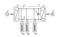
図1は、本発明の好適な実施の形態にかかる回生制動装置の接続構成を示す図である。同図において、インバータ装置1は、例えば3相の交流電源である交流電源2に接続され、交流電源2の交流電力を直流電力に変換するコンバータ部3と、コンバータ部3の出力側に接続された平滑コンデンサ6と、コンバータ部3が出力する直流電力を可変電圧および可変周波数の交流電力に再変換するインバータ部7と、を備えている。また、インバータ装置1の出力端、すなわちインバータ部7の出力端には、例えば3相交流電力で運転される駆動用モータ8が接続されるとともに、コンバータ部3とインバータ部7との間を接続する一対の直流母線4,5の間には、複数の制動装置(回生制動装置)10(10a,10b,…,10n)が、並列に接続されている。
【0013】
図1において、複数の制動装置10は、自己の内部に有する抵抗器などで、駆動用モータ8(負荷側)からインバータ装置1側に回生される回生電力(電気エネルギー)を熱エネルギーに変換して消費する。なお、複数台の制動装置を並列に接続するようにしているのは、各制動装置では、所定の定格に基づく消費電力が定められているからである。例えば、200kWの駆動用モータが接続されている場合であって、駆動用モータ側から100kWの回生電力の戻りがある場合を考える。このとき、制動装置10台の消費電力定格が20kwの場合には、100(kW)=20(kW/台)×5(台)となって、最低でも5台の制動装置が必要となる。なお、消費電力定格の大きな制動装置はサイズが大きく、また、価格も高価であるため、可能な限り定格の小さな制動装置を使用することが好ましい。このような理由により、複数の制動装置を並列運転する必要性が生ずることになる。
【0014】
図2は、図1に示した制動装置10の細部構成を示す図である。図2において、制動装置10は、制動抵抗11、スイッチング回路12、電圧検出器14、動作レベル演算器15、比較器16および駆動回路17の各構成部を備えて構成される。制動抵抗11およびスイッチング回路12は、直流母線4,5にそれぞれ接続された端子18,19の各端子間に直列に挿入される。駆動回路17は、比較器16の出力に基づいてスイッチング回路12を制御する。例えば、スイッチング回路12がオン制御されるとインバータ装置1の平滑コンデンサ6に蓄積された電荷が制動抵抗11を通じて放電され、制動抵抗11において負荷側からの回生電力が消費される。
【0015】
また、動作レベル演算器15は、後述するような所定(可変)レベルの電圧信号を生成する。一方、電圧検出器14は、例えば直流母線4(すなわち平滑コンデンサ6)の出力電圧(直流電圧)に基づくモニタ電圧を出力する。なお、電圧検出器14が出力するモニタ電圧は、例えば平滑コンデンサ6の電圧値そのものではなく、当該電圧値に比例(相当)する電圧値であればよい。比較器16は、電圧検出器14から出力されるモニタ電圧と動作レベル演算器15から出力される演算出力とに基づいてスイッチング回路12への制御信号を生成し、駆動回路17を通じてスイッチング回路12を制御する。例えば、電圧検出器14のモニタ電圧が動作レベル演算器15の演算出力よりも大きい場合には、回生電力を消費させる必要があり、スイッチング回路12がオン制御される。一方、電圧検出器14のモニタ電圧が動作レベル演算器15の演算出力よりも小さい場合には、回生電力を消費させる必要がなく、スイッチング回路12はオフ制御される。
【0016】
図3は、本発明にかかる回生制動装置の動作の説明するための一例を示す図である。より詳細には、例えば図2に示す構成の制動装置を2台接続したときの動作を時間軸上に示した図である。図3において、実線で示す波形K1は、電圧検出器14のモニタ電圧であり、一点鎖線で示す波形K2は、2台の制動装置のうちの一方の制動装置(「制動装置10a」とする)の動作レベル演算器が出力する動作レベル電圧を示している。
【0017】
また、電圧レベルVL1,VH1は、制動装置10aの動作レベル範囲を決定する電圧であり、電圧レベルVL2,VH2は、2台の制動装置のうちの他方の制動装置(「制動装置10b」とする)の動作レベル範囲を決定する電圧である。なお、動作レベル範囲の下限値である電圧レベルVL1,VL2は、上記したように、部品公差等により各々の制動装置間で異なっているのが通常である。したがって、図3に示す例では、制動装置10aにおける動作レベル範囲の下限値が制動装置10bにおける動作レベル範囲の下限値よりも小さい場合を想定して示している。一方、動作レベル範囲の上限値である電圧レベルVH1,VH2は、制動装置の耐圧等を考慮して決定される電圧値であり、その下限値と同様、図3に示すように、制動装置10aの値が制動装置10bの値よりも小さい場合を想定して示している。なお、これらの想定例は便宜上のものであり、各制動装置の動作を規定したり、制約を与えたりするものではない。
【0018】
つぎに、本発明にかかる回生制動装置の動作について図3を参照して説明する。なお、制動装置10の制動抵抗11に電流が流れて回生電力が消費される場合を「オン」の状態とし、逆に、制動抵抗11に電流が流れず、回生電力が消費されない場合を「オフ」の状態として以下の説明を行う。なお、制動装置10aにおける電圧検出器14のモニタ電圧と制動装置10bにおける電圧検出器14のモニタ電圧とは、同一端子の電圧をモニタしている関係上同一の値をとる。したがって、以下、各制動装置における各電圧検出器のモニタ電圧を、制動装置10a,10bを区別することなく単に「モニタ電圧」として説明する。
【0019】
まず、A点までの間では、各モニタ電圧が制動装置10aの動作レベル下限値(VL1)および制動装置10bの動作レベル下限値(VL2)よりも小さく、制動装置10a,10bともにオフの状態となる。
【0020】
つぎに、A点〜B点までの区間では、モニタ電圧が制動装置10aの動作レベル下限値(VL1)よりも大きくなり、制動装置10aはオンとなる。このとき、制動装置10aは、自己の動作レベル演算器15における動作レベル下限値を上昇させる制御を行う。ここで、自己の動作レベル下限値の上昇処理は、例えば自己の通電時間を時間積分するなどの手法を用いて行うことができる。一方、制動装置10bは、モニタ電圧が自己の動作レベル下限値(VL2)よりも小さい状態が続いてオフの状態を継続する。
【0021】
つぎに、B点〜C点までの区間では、モニタ電圧が制動装置10aの動作レベル下限値(VL1)よりも小さくなり、制動装置10aはオフとなる。このとき、制動装置10aは、自己の動作レベル下限値を下降させる制御を行う。一方、制動装置10bは、A点〜B点までの区間に引き続き、オフの状態を継続する。
【0022】
さらに、C点〜E点までの区間では、モニタ電圧が制動装置10aの動作レベル下限値(VL1)よりも大きくなり、制動装置10aは再度オンとなり、自己の動作レベル下限値を上昇させる制御を行う。一方、制動装置10bは、C点〜D点までの区間では、モニタ電圧が自己の動作レベル下限値(VL2)よりも小さいのでオフの状態を継続するが、D点〜E点までの区間では、モニタ電圧が自己の動作レベル下限値(VL2)よりも大きくなってオンの状態となる。このとき、制動装置10bは、制動装置10aと同様に、自己の動作レベル下限値を上昇させる制御を行う。なお、図3の例では、図示の煩雑さを避けるため、制動装置10bの動作レベル下限値の図示を省略している。
【0023】
以下、E点以降の区間では、モニタ電圧と自己の動作レベル下限値との比較結果に基づいて、制動装置10a,10bの状態が変更される。なお、各制動装置は、後述のように、自己の動作レベル下限値を自己の動作時間に応じて、上昇または下降する制御を行うことで、各制動装置間における動作レベル下限値のバラツキが解消される。例えば、図3の例では、動作開始前は、制動装置10aの動作レベル下限値(VL1)が制動装置10bの動作レベル下限値(VL2)よりも小さい状態であったが、制動装置10aのオン時間が制動装置10bのオン時間よりも長いため、制動装置10aの動作レベル下限値(VL1)の上昇率が制動装置10bの動作レベル下限値(VL2)の上昇率を上回るとともに、制動装置10aのオフ時間が制動装置10bのオフ時間よりも短いため、制動装置10aの動作レベル下限値(VL1)の下降率が制動装置10bの動作レベル下限値(VL2)の下降率を下回ることになる。その結果、図3に示すE点以降の区間では、制動装置10a,10b間における動作レベル下限値のバラツキが解消され、制動装置10a,10bにおける動作の均一性が確保される。
【0024】
上述のように、本発明の好適な実施の形態にかかる回生制動装置は、他の回生制動装置の動作情報(あるいは制御情報)に依存することなく、自己の動作レベルを可変制御することに特徴がある。すなわち、本発明の好適な実施の形態にかかる回生制動装置は、他の回生制動装置の動作に依存しない自己完結型の動作レベル可変機能を有していると言える。
【0025】
つぎに、制動装置の動作時間と動作レベル演算器の動作レベルとの関係について図4を参照して説明する。ここで、図4は、制動装置の動作時間に応じて上昇または下降する動作レベル下限値の出力波形の一例を示す図である。
【0026】
図4に示す波形fL1(t)は、動作時間に応じて可変制御された動作レベル演算器の動作レベル下限値の一例を示している。例えば、時刻t0のときの動作レベル下限値をfL10とすると、まず、制動装置がオフの状態からオンの状態に移行し、そのオンの状態を継続する時刻t0〜t1(オン時間T1)の間では、動作レベル下限値をfL10から所定の上昇率(M1)で上昇させる。一方、制動装置がオンの状態からオフの状態に移行し、そのオフの状態を継続する時刻t1〜t2(オフ時間T2)の間では、動作レベル下限値を、その時点の値から所定の下降率(M2)で下降させる。なお、上昇率M1および下降率M2が、それぞれ正の値をとるものとすれば、これらの間には、M1>M2の関係にあることが好ましい。
【0027】
また、上昇率M1と下降率M2との相対的な関係とは離れて、上昇率M1の値を比較的大きな値に設定することにより、制動装置間の動作レベル下限値の初期のバラツキが早期に解消されるという効果がある。一方、下降率M2の値を比較的小さな値に設定することにより、非動作の制動装置における動作レベル下限値が必要以上に下降するのを防止することができるという効果がある。
【0028】
なお、制動装置では、抵抗器の熱時定数や放熱能力等に応じて、連続オンに対する許容時間や、連続オン後の休止時間等が定められているので、これらの特性を考慮することが好ましい。例えば、連続オンの許容時間および連続オン後の休止時間が、それぞれ1分、5分程度に設定されている場合、動作レベル下限値の上昇率M1を下降率M2の5〜10倍に設定することが好適である。
【0029】
なお、上記の説明では、制動装置がオンの状態において、動作レベル下限値を所定の上昇率で上昇させるものとしているが、動作レベル下限値を動作レベル上限値以上に上昇させることがないことは勿論である。また、制動装置がオフの状態において、動作レベル下限値を所定の下降率で下降させるものとしているが、初期設定された動作レベル下限値以下に下降させることがないことも勿論である。
【0030】
また、この実施の形態では、制動装置がオフの状態において、動作レベル下限値を所定の下降率で下降させるようにしているが、制動装置の耐圧等を考慮して決定される動作レベル上限値の各制動装置におけるバラツキが小さい場合には、制動装置がオフの状態時に、動作レベル下限値を下降させる制御を行わないようにしてもよい。このような制御であっても、動作レベル下限値がある時点で一致した制動装置間のオフ時間およびオン時間の時比率が一致するとともに、他の制動装置との間においても、これらの関係が連鎖的に成立し、各制動装置間における動作レベル下限値のバラツキが解消される。
【0031】
また、制動装置間における動作レベル上限値のバラツキが比較的大きい場合であっても、例えば各制動装置における動作レベル上限値のうちの最も小さな値を各制動装置間に共通な動作レベル上限値として設定することにより、上記と同様に、動作レベル下限値の下降制御を省略することができる。
【0032】
以上説明したように、この実施の形態の回生制動装置によれば、インバータ装置などの電力供給装置に複数の回生制動装置を接続する場合、回生電力を消費する回生制動装置の通電時間に応じて演算された動作レベルと回生電力をモニタしたモニタ出力との比較結果に基づいて回生制動装置の通電時間を制御するようにしているので、各々の装置の動作レベルに部品公差等が存在する場合であっても、各装置を均一に動作させることができる。また、この実施の形態の回生制動装置では、各装置間を制御線等によって接続する必要がないので、装置全体の信頼性の低下を招来することがない。
【産業上の利用可能性】
【0033】
以上のように、本発明にかかる回生制動装置は、インバータ装置などの電力供給装置に複数の回生制動装置を並列に接続する場合に有用であり、特に、複数の回生制動装置間の動作の均一性を確保する場合に好適である。【Technical field】
[0001]
The present invention relates to a regenerative braking device that is connected to a power supply device such as an inverter device that supplies power to a load and consumes regenerative power regenerated from the load side.
[Background]
[0002]
When a plurality of regenerative braking devices are connected in parallel to a power supply device such as an inverter device, the operation level of each regenerative braking device is not uniform due to component tolerances, etc., so that the operation is concentrated only on some regenerative braking devices. Such a situation occurs. In particular, when such operation non-uniformity occurs between the regenerative braking devices, the deterioration of the parts of the regenerative braking device where the operations are concentrated proceeds rapidly, leading to a decrease in the reliability of the entire system. Therefore, it is necessary to avoid the concentration of the operation only on a part of the regenerative braking devices and to ensure the uniformity of the operation between the regenerative braking devices.
[0003]
For example, in the following Patent Document 1, even if an error occurs in the braking setting level of each braking device connected in parallel to the inverter device, a technique for preventing the duty from being concentrated on the switching element and the braking resistance of the specific braking device. Is disclosed.
[0004]
[Patent Document 1]
JP 10-131206 A DISCLOSURE OF THE INVENTION
[Problems to be solved by the invention]
[0005]
However, in the technique disclosed in Patent Literature 1, each braking device outputs a braking start signal generated by itself to another braking device, and also inputs a braking start signal generated by another braking device to itself. There was a need. In other words, it is necessary to connect each braking device with a plurality of signal lines (control lines). The connection becomes complicated as the number of braking devices increases, and the entire system is caused by disconnection, poor contact, etc. There was a problem that reliability was lowered.
[0006]
The present invention has been made in view of the above, and when connecting a plurality of regenerative braking devices to a power supply device such as an inverter device, there is a case where there is a component tolerance or the like in the operation level of each device. Another object of the present invention is to provide a regenerative braking device that operates each device uniformly, eliminates the need for connection between the devices by a control line or the like, and does not cause a decrease in reliability.
Means for Solving the Problems [0007]
In order to solve the above-described problems and achieve the object, a regenerative braking device according to the present invention is connected to a power supply device that supplies power to a load, and loads together with other regenerative braking devices connected to the power supply device. In the regenerative braking device that consumes regenerative power regenerated from the side, consumption means for consuming the regenerative power, energization means for energizing the regenerative power to the consumption means, monitor means for monitoring the regenerative power, and The operation level change for calculating the lower limit value of the operation level for determining whether or not to operate the energization means as needed according to the energization time of the consuming means, and changing the calculated lower limit value of the operation level and outputting it Based on the comparison result of the comparison means, the comparison means for comparing the lower limit value of the action level output by the action level changing means and the monitor output of the monitor means Said drive means for driving the energizing means, wherein the and the lower limit of the operating level the monitor output is above conductive member, characterized in that the work.
Effect of the Invention [0008]
According to the regenerative braking device of the present invention, when a plurality of regenerative braking devices are connected to the power supply device, the lower limit value of the operation level calculated at any time is changed according to the energization time of the regenerative braking device that consumes the regenerative power. The regenerative braking device energization time is controlled based on the comparison result between the lower limit value of the changed operation level and the monitor output monitoring the regenerative power. Even when the operation level of the apparatus is not uniform, each apparatus can be operated uniformly, and it is not necessary to connect each apparatus by a control line or the like, resulting in a decrease in reliability of the entire apparatus. The effect that there is no is obtained.
[Brief description of the drawings]
[0009]
FIG. 1 is a diagram showing a connection configuration of a regenerative braking device according to a preferred embodiment of the present invention.
FIG. 2 is a diagram showing a detailed configuration of the braking device shown in FIG.
FIG. 3 is a diagram showing an example for explaining the operation of the regenerative braking device according to the present invention.
[FIG. 4] FIG. 4 is a diagram showing an example of an output waveform of an operation level lower limit value that rises or falls according to the operation time of the braking device.
[Explanation of symbols]
[0010]
DESCRIPTION OF SYMBOLS 1 Inverter apparatus 2 AC power source 3
[0011]
Preferred embodiments of a regenerative braking device according to the present invention will be described below in detail with reference to the drawings. In addition, this invention is not limited by this embodiment. Moreover, in embodiment shown below, although the case where a regenerative braking apparatus is connected to an inverter apparatus is demonstrated as an example, it is not limited to an inverter apparatus as a connection place, It is with respect to electric power supply apparatuses other than an inverter apparatus. Even can be applied.
[0012]
Embodiment 1 FIG.
FIG. 1 is a diagram showing a connection configuration of a regenerative braking device according to a preferred embodiment of the present invention. In FIG. 1, an inverter device 1 is connected to an AC power source 2 that is a three-phase AC power source, for example, and is connected to a converter unit 3 that converts AC power of the AC power source 2 into DC power, and an output side of the converter unit 3. The smoothing capacitor 6 and the inverter unit 7 that reconverts the DC power output from the converter unit 3 into AC power having a variable voltage and a variable frequency. In addition, a drive motor 8 operated with, for example, three-phase AC power is connected to the output terminal of the inverter device 1, that is, the output terminal of the inverter unit 7, and the converter unit 3 and the inverter unit 7 are connected to each other. A plurality of braking devices (regenerative braking devices) 10 (10a, 10b,..., 10n) are connected in parallel between the pair of
[0013]
In FIG. 1, a plurality of
[0014]
FIG. 2 is a diagram illustrating a detailed configuration of the
[0015]
Further, the
[0016]
FIG. 3 is a diagram showing an example for explaining the operation of the regenerative braking device according to the present invention. More specifically, for example, FIG. 3 is a diagram showing an operation on the time axis when two braking devices having the configuration shown in FIG. 2 are connected. In FIG. 3, a waveform K1 indicated by a solid line is a monitor voltage of the
[0017]
The voltage levels VL1 and VH1 are voltages that determine the operating level range of the braking device 10a, and the voltage levels VL2 and VH2 are the other braking device (“braking device” of the two braking devices). 10b ") to determine the operation level range. As described above, the voltage levels VL1 and VL2 that are the lower limit values of the operation level range are usually different between the respective braking devices due to component tolerances and the like. Therefore, in the example shown in FIG. 3, it is assumed that the lower limit value of the operation level range in the braking device 10a is smaller than the lower limit value of the operation level range in the
[0018]
Next, the operation of the regenerative braking device according to the present invention will be described with reference to FIG. The state where the current flows through the braking resistor 11 of the
[0019]
First, until the point A, each monitor voltage is smaller than the operating level lower limit value (VL1 ) of the braking device 10a and the operating level lower limit value (VL2 ) of the
[0020]
Next, in the section from the point A to the point B, the monitor voltage becomes larger than the operation level lower limit (VL1 ) of the braking device 10a, and the braking device 10a is turned on. At this time, the braking device 10a performs control to increase the operation level lower limit value of its own
[0021]
Next, in the section from point B to point C, the monitor voltage becomes lower than the operating level lower limit value (VL1 ) of the braking device 10a, and the braking device 10a is turned off. At this time, the braking device 10a performs control to lower its own operation level lower limit value. On the other hand, the
[0022]
Further, in the section from the point C to the point E, the monitor voltage becomes larger than the operating level lower limit value (VL1 ) of the braking device 10a, the braking device 10a is turned on again, and the control for increasing the own operating level lower limit value is performed. I do. On the other hand, the
[0023]
Hereinafter, in the section after point E, the states of the
[0024]
As described above, the regenerative braking device according to a preferred embodiment of the present invention is characterized in that its own operation level is variably controlled without depending on the operation information (or control information) of other regenerative braking devices. There is. That is, it can be said that the regenerative braking device according to the preferred embodiment of the present invention has a self-contained operation level variable function that does not depend on the operation of other regenerative braking devices.
[0025]
Next, the relationship between the operation time of the braking device and the operation level of the operation level calculator will be described with reference to FIG. Here, FIG. 4 is a diagram illustrating an example of an output waveform of an operation level lower limit value that increases or decreases according to the operation time of the braking device.
[0026]
A waveform fL1 (t) shown in FIG. 4 shows an example of the operation level lower limit value of the operation level calculator that is variably controlled according to the operation time. For example, if the operation level lower limit value at time t0 isfL10 , first, at time t0 to t1 (on time T1) when the braking device shifts from the off state to the on state and continues the on state. In themeantime, the lower limit value of the operation level is increased from fL10 at a predetermined increase rate (M1). On the other hand, during the time t1 to t2 (off time T2) in which the braking device shifts from the on state to the off state and continues the off state, the operation level lower limit value is lowered by a predetermined amount from the value at that time. Lower at rate (M2). Note that if the rate of increase M1 and the rate of decrease M2 are positive values, it is preferable that there is a relationship of M1> M2.
[0027]
Further, apart from the relative relationship between the rate of increase M1 and the rate of decrease M2, by setting the value of the rate of increase M1 to a relatively large value, the initial variation in the operation level lower limit value between the braking devices is early. This has the effect of being eliminated. On the other hand, by setting the value of the descent rate M2 to a relatively small value, there is an effect that it is possible to prevent the operation level lower limit value in the non-operating braking device from falling more than necessary.
[0028]
In the braking device, the allowable time for continuous ON, the pause time after continuous ON, etc. are determined according to the thermal time constant, heat dissipation capability, etc. of the resistor, so it is preferable to consider these characteristics. . For example, when the allowable time for continuous ON and the pause time after continuous ON are set to about 1 minute and 5 minutes, respectively, the increase rate M1 of the operation level lower limit value is set to 5 to 10 times the decrease rate M2. Is preferred.
[0029]
In the above description, the operation level lower limit value is increased at a predetermined increase rate when the braking device is on. However, the operation level lower limit value is not increased beyond the operation level upper limit value. Of course. Further, in the state where the braking device is off, the operation level lower limit value is lowered at a predetermined rate of decrease, but it goes without saying that the operation level lower limit value is not lowered below the initially set operation level lower limit value.
[0030]
Further, in this embodiment, the operation level lower limit value is lowered at a predetermined lowering rate when the braking device is off, but the operation level upper limit value determined in consideration of the pressure resistance of the braking device and the like. When the variation among the braking devices is small, the control for lowering the operation level lower limit value may not be performed when the braking device is off. Even with such control, the off-time and on-time time ratios between the braking devices that coincide at a certain point in time when the operation level is lower are the same, and the relationship between the braking devices and other braking devices is also the same. It is established in a chain, and the variation in the lower limit value of the operation level between the braking devices is eliminated.
[0031]
Further, even when the variation in the operation level upper limit value between the braking devices is relatively large, for example, the smallest value among the operation level upper limit values in each braking device is set as the operation level upper limit value common to the braking devices. By setting, the lowering control of the operation level lower limit value can be omitted as described above.
[0032]
As described above, according to the regenerative braking device of this embodiment, when a plurality of regenerative braking devices are connected to a power supply device such as an inverter device, according to the energization time of the regenerative braking device that consumes regenerative power. Since the energization time of the regenerative braking device is controlled based on the comparison result between the calculated operation level and the monitor output obtained by monitoring the regenerative power, there is a part tolerance etc. in the operation level of each device. Even if it exists, each apparatus can be operated uniformly. Further, in the regenerative braking device of this embodiment, since it is not necessary to connect each device by a control line or the like, the reliability of the entire device is not lowered.
[Industrial applicability]
[0033]
As described above, the regenerative braking device according to the present invention is useful when a plurality of regenerative braking devices are connected in parallel to a power supply device such as an inverter device, and in particular, uniform operation between the plurality of regenerative braking devices. It is suitable for securing the property.
Claims (6)
Translated fromJapanese前記回生電力を消費する消費手段と、
前記回生電力を前記消費手段に通電させる通電手段と、
前記回生電力をモニタするモニタ手段と、
前記通電手段を動作させるか否かを判定するための動作レベルの下限値を前記消費手段の通電時間に応じて随時演算するとともに、該演算した動作レベルの下限値を変更して出力する動作レベル変更手段と、
前記動作レベル変更手段が出力する動作レベルの下限値と前記モニタ手段のモニタ出力とを比較する比較手段と、
前記比較手段の比較結果に基づいて前記通電手段を駆動する駆動手段と、
を備え、
前記動作レベルの下限値を前記モニタ出力が上回ると前記通電手段が動作する
ことを特徴とする回生制動装置。In a regenerative braking device that is connected to a power supply device that supplies power to a load and consumes regenerative power regenerated from the load side together with other regenerative braking devices connected to the power supply device,
Consumption means for consuming the regenerative power;
Energization means for energizing the consumption means with the regenerative power;
Monitoring means for monitoring the regenerative power;
An operation level for calculating the lower limit value of the operation level for determining whether or not to operate the energization means as needed according to the energization time of the consumption means, and changing and outputting the lower limit value of the calculated operation level Change means,
Comparison means for comparing the lower limit value of the operation level output by the operation level change means with the monitor output of the monitor means;
Drive means for driving the energization means based on the comparison result of the comparison means;
With
The regenerative braking device, wherein the energization means operates when the monitor output exceeds a lower limit value of the operation level.
Applications Claiming Priority (1)
| Application Number | Priority Date | Filing Date | Title |
|---|---|---|---|
| PCT/JP2006/313019WO2008001450A1 (en) | 2006-06-29 | 2006-06-29 | Regenerative braking device |
Publications (2)
| Publication Number | Publication Date |
|---|---|
| JPWO2008001450A1 JPWO2008001450A1 (en) | 2009-11-26 |
| JP4778055B2true JP4778055B2 (en) | 2011-09-21 |
Family
ID=38845225
Family Applications (1)
| Application Number | Title | Priority Date | Filing Date |
|---|---|---|---|
| JP2008522253AExpired - Fee RelatedJP4778055B2 (en) | 2006-06-29 | 2006-06-29 | Regenerative braking device |
Country Status (8)
| Country | Link |
|---|---|
| US (1) | US8217599B2 (en) |
| JP (1) | JP4778055B2 (en) |
| KR (1) | KR101120757B1 (en) |
| CN (1) | CN101473523B (en) |
| DE (1) | DE112006003938T5 (en) |
| GB (1) | GB2453878B (en) |
| TW (1) | TWI334262B (en) |
| WO (1) | WO2008001450A1 (en) |
Families Citing this family (10)
| Publication number | Priority date | Publication date | Assignee | Title |
|---|---|---|---|---|
| JP2010110139A (en)* | 2008-10-31 | 2010-05-13 | Fuji Electric Systems Co Ltd | Method for processing regenerative electric power of inverter device |
| US8427086B2 (en)* | 2010-04-26 | 2013-04-23 | Deere & Company | Brake resistor control |
| TWI482419B (en)* | 2011-02-21 | 2015-04-21 | Legendaire Technology Co Ltd | Motor control system and method and brake device |
| JP5864219B2 (en)* | 2011-11-08 | 2016-02-17 | 平田機工株式会社 | Control method and control apparatus |
| CN102832868B (en)* | 2012-08-21 | 2015-02-18 | 湖北立锐机电有限公司 | Energy consumption brakingbraking device and method for servo driver |
| JP5670398B2 (en) | 2012-09-10 | 2015-02-18 | ファナック株式会社 | Motor control device having at least two resistance discharge means |
| WO2015004891A1 (en)* | 2013-07-10 | 2015-01-15 | パナソニックIpマネジメント株式会社 | Semiconductor device and inverter using same |
| WO2016015072A1 (en)* | 2014-07-29 | 2016-02-04 | SIMA, Ewald | Closed-loop control and open-loop control of a single-phase or polyphase electromagnetic lathe |
| CN107623465B (en)* | 2017-09-21 | 2020-04-14 | 中科新松有限公司 | A braking method, braking unit and robot |
| US10958188B1 (en)* | 2019-09-25 | 2021-03-23 | Eaton Intelligent Power Limited | Bus voltage limiter for converter apparatus with multiple DC buses |
Family Cites Families (8)
| Publication number | Priority date | Publication date | Assignee | Title |
|---|---|---|---|---|
| JPS59127584A (en) | 1983-01-11 | 1984-07-23 | Hitachi Ltd | Regenerative brake unit |
| JPH05115187A (en)* | 1991-10-22 | 1993-05-07 | Fuji Electric Co Ltd | Overheated state deciding method for regenerative resistor |
| JPH05168287A (en)* | 1991-12-16 | 1993-07-02 | Meidensha Corp | Detecting method for dbr overload of inverter |
| CN2192980Y (en)* | 1993-02-20 | 1995-03-22 | 阜新矿务局科学技术开发服务部 | Self-feedback regenerative braking device for mine hoist |
| JPH10131206A (en) | 1996-11-05 | 1998-05-19 | Hitachi Cable Ltd | Telescopic inner formwork for hollow foundation |
| JP3627842B2 (en)* | 1998-07-15 | 2005-03-09 | 富士電機機器制御株式会社 | Induction motor control device |
| US6702052B1 (en) | 1999-09-22 | 2004-03-09 | Honda Giken Kogyo Kabushiki Kaisha | Control apparatus for hybrid vehicles |
| US7012392B2 (en)* | 2004-02-06 | 2006-03-14 | Honeywell International Inc. | Multi-stage dynamic braking resistor network |
- 2006
- 2006-06-29KRKR1020087030974Apatent/KR101120757B1/ennot_activeExpired - Fee Related
- 2006-06-29WOPCT/JP2006/313019patent/WO2008001450A1/enactiveApplication Filing
- 2006-06-29JPJP2008522253Apatent/JP4778055B2/ennot_activeExpired - Fee Related
- 2006-06-29USUS12/306,672patent/US8217599B2/ennot_activeExpired - Fee Related
- 2006-06-29GBGB0823613Apatent/GB2453878B/ennot_activeExpired - Fee Related
- 2006-06-29CNCN2006800551614Apatent/CN101473523B/ennot_activeExpired - Fee Related
- 2006-06-29DEDE112006003938Tpatent/DE112006003938T5/ennot_activeWithdrawn
- 2006-07-25TWTW095127063Apatent/TWI334262B/ennot_activeIP Right Cessation
Also Published As
| Publication number | Publication date |
|---|---|
| DE112006003938T5 (en) | 2009-05-07 |
| US8217599B2 (en) | 2012-07-10 |
| TW200803148A (en) | 2008-01-01 |
| TWI334262B (en) | 2010-12-01 |
| WO2008001450A1 (en) | 2008-01-03 |
| GB2453878B (en) | 2011-05-25 |
| KR20090018653A (en) | 2009-02-20 |
| JPWO2008001450A1 (en) | 2009-11-26 |
| US20090200969A1 (en) | 2009-08-13 |
| KR101120757B1 (en) | 2012-03-23 |
| CN101473523B (en) | 2013-02-20 |
| CN101473523A (en) | 2009-07-01 |
| GB2453878A (en) | 2009-04-22 |
| GB0823613D0 (en) | 2009-02-04 |
Similar Documents
| Publication | Publication Date | Title |
|---|---|---|
| JP4778055B2 (en) | Regenerative braking device | |
| CN103684190B (en) | Motor control device with at least two resistive discharge units | |
| US20160187948A1 (en) | Power supply device | |
| CN107317485B (en) | Apparatus for controlling the operation of a power conversion device | |
| TW201407919A (en) | Power system with combination of active current sharing and droop current sharing and power system assembly using the same | |
| JP2010110139A (en) | Method for processing regenerative electric power of inverter device | |
| CN103248308B (en) | Method for controlling inverter | |
| JP6513293B1 (en) | Motor drive system and inverter device | |
| JP5259941B2 (en) | Inverter device and air conditioner | |
| CN105453401B (en) | Stand-by power supply controls | |
| US7141947B2 (en) | Braking chopper | |
| CN103595038B (en) | Active current sharing and step-down current sharing combined application power system and power system combination | |
| WO2015190421A1 (en) | Electronic control device | |
| JP5034914B2 (en) | Elevator control device | |
| JP6497081B2 (en) | Braking resistance control device and braking resistance control method | |
| JP7259638B2 (en) | voltage converter | |
| JPWO2019017119A1 (en) | Load control device | |
| JP7326440B2 (en) | Converter equipment, industrial machinery | |
| CN114174102B (en) | Method and system for operating a system having an energy store and a resistor | |
| JP2012175871A (en) | Motor controller and system | |
| JP2011188549A (en) | Power unit, and method of controlling the same | |
| JP2017017925A (en) | Motor drive device | |
| JPH09121561A (en) | Method of treating regenerative energy of inverter and regenerative energy treating apparatus | |
| JP2002223592A (en) | Common rectifying inverter | |
| JP2013135498A (en) | Controller of elevator |
Legal Events
| Date | Code | Title | Description |
|---|---|---|---|
| TRDD | Decision of grant or rejection written | ||
| A01 | Written decision to grant a patent or to grant a registration (utility model) | Free format text:JAPANESE INTERMEDIATE CODE: A01 Effective date:20110628 | |
| A01 | Written decision to grant a patent or to grant a registration (utility model) | Free format text:JAPANESE INTERMEDIATE CODE: A01 | |
| A61 | First payment of annual fees (during grant procedure) | Free format text:JAPANESE INTERMEDIATE CODE: A61 Effective date:20110630 | |
| R150 | Certificate of patent or registration of utility model | Free format text:JAPANESE INTERMEDIATE CODE: R150 | |
| FPAY | Renewal fee payment (event date is renewal date of database) | Free format text:PAYMENT UNTIL: 20140708 Year of fee payment:3 | |
| LAPS | Cancellation because of no payment of annual fees |