JP4777990B2 - Determine and configure paths in the network - Google Patents
Determine and configure paths in the networkDownload PDFInfo
- Publication number
- JP4777990B2 JP4777990B2JP2007534687AJP2007534687AJP4777990B2JP 4777990 B2JP4777990 B2JP 4777990B2JP 2007534687 AJP2007534687 AJP 2007534687AJP 2007534687 AJP2007534687 AJP 2007534687AJP 4777990 B2JP4777990 B2JP 4777990B2
- Authority
- JP
- Japan
- Prior art keywords
- network
- routing
- path
- network element
- link
- Prior art date
- Legal status (The legal status is an assumption and is not a legal conclusion. Google has not performed a legal analysis and makes no representation as to the accuracy of the status listed.)
- Expired - Fee Related
Links
Images


Classifications
- H—ELECTRICITY
- H04—ELECTRIC COMMUNICATION TECHNIQUE
- H04L—TRANSMISSION OF DIGITAL INFORMATION, e.g. TELEGRAPHIC COMMUNICATION
- H04L41/00—Arrangements for maintenance, administration or management of data switching networks, e.g. of packet switching networks
- H04L41/08—Configuration management of networks or network elements
- H04L41/0803—Configuration setting
- H04L41/0806—Configuration setting for initial configuration or provisioning, e.g. plug-and-play
- H—ELECTRICITY
- H04—ELECTRIC COMMUNICATION TECHNIQUE
- H04L—TRANSMISSION OF DIGITAL INFORMATION, e.g. TELEGRAPHIC COMMUNICATION
- H04L41/00—Arrangements for maintenance, administration or management of data switching networks, e.g. of packet switching networks
- H04L41/12—Discovery or management of network topologies
- H—ELECTRICITY
- H04—ELECTRIC COMMUNICATION TECHNIQUE
- H04L—TRANSMISSION OF DIGITAL INFORMATION, e.g. TELEGRAPHIC COMMUNICATION
- H04L45/00—Routing or path finding of packets in data switching networks
- H04L45/56—Routing software
- H04L45/563—Software download or update
Landscapes
- Engineering & Computer Science (AREA)
- Computer Networks & Wireless Communication (AREA)
- Signal Processing (AREA)
- Data Exchanges In Wide-Area Networks (AREA)
Description
Translated fromJapanese本発明は、ネットワークにおけるパスの決定および設定に関する。 The present invention relates to path determination and setting in a network.
本出願は、2004年9月30日に出願した米国仮出願番号第60/614,609の優先権を主張するとともに、参照により、そのすべての開示内容を本明細書の一部とする。 This application claims priority from US Provisional Application No. 60 / 614,609, filed Sep. 30, 2004, the entire disclosure of which is hereby incorporated by reference.
次世代広帯域ネットワークなどの通信ネットワークは、増加する規模、多数の混在する技術/プロトコル(例えば、ATM、フレーム・リレイなど)、および多数の異なった業者により製造された設備の混在により、ますます複雑になってきている。結果として、これらのネットワーク中で仮想的なトランクおよび回線(virtual trunks and circuits)を設定可能な、ネットワーク構成管理システムが、ますます重要になっている。そのようなネットワーク構成管理システムは、ここでネットワーク要素(network element)と呼ばれるネットワーク設備の間のパス/ルートを決定するように、そしてそれらのネットワーク要素と通信して、ネットワークを通るトラフィックの伝送を促進するのに必要なトランクまたは回線を実現するように機能する。 Communication networks, such as next generation broadband networks, are becoming increasingly complex due to the increasing scale, the number of mixed technologies / protocols (eg, ATM, frame relay, etc.), and the mix of equipment manufactured by many different vendors. It is becoming. As a result, network configuration management systems that can set up virtual trunks and circuits in these networks are becoming increasingly important. Such a network configuration management system communicates with these network elements to determine the paths / routes between network facilities, referred to herein as network elements, and to transmit traffic through the network. Acts to provide the trunk or line necessary to facilitate.
一般にネットワーク構成管理システムは伝統的に、ネットワーク要素の部分を図表上にノードとしてモデル化することにより利用可能なパスを、およびノードの間のリンクとして、これらの部分の間のリンク/相互接続を決定してきた。より詳細には、従来のシステムは通常、あらゆるネットワーク要素のあらゆるポートを図表上にノードとしてモデル化し、そしてこれらのポートをお互いに相互接続するあらゆる物理的なリンクを、図表上のノードを相互接続するリンクとして、モデル化した。そしてネットワーク・モデルは、ネットワークにおけるネットワーク要素の間のパスを形成する仮想的なトランクを設定するために使用された。これらの仮想的なトランクが設定されると、次にこれらのトランクを通して仮想的な回線が確立され、ネットワークにおいてある点から他の点へのトラフィックの流れを支援することが可能となった。 In general, network configuration management systems traditionally provide available paths by modeling parts of network elements as nodes on a diagram, and links / interconnects between these parts as links between nodes. I have decided. More specifically, traditional systems typically model every port on every network element as a node on the diagram, and interconnect every physical link that interconnects these ports to each other, nodes on the diagram. Modeled as a link to. The network model was then used to set up virtual trunks that form paths between network elements in the network. Once these virtual trunks were set up, virtual circuits were then established through these trunks, and it became possible to support the flow of traffic from one point to another in the network.
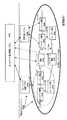
図1は、代表的従来技術のネットワーク構成管理システム102およびシステム102によって管理されるネットワーク110を示す。ネットワーク構成管理システム102は、ネットワークにおける2点間の(すなわち、2つのネットワーク要素の間の)好適なパスを決定するように、そして管理されたネットワーク110と通信することによって、このパスを通して通信接続を設定するように機能する。管理されるネットワーク110はさらに主として、図1においてリンク120〜124により表された物理的なリンクおよび仮想的なトランクおよび回線により相互接続された複数のネットワーク要素114〜118より成る、広帯域ネットワーク112から成る。ネットワーク要素は、様々な技術およびプロトコルを具備し、そして異なった業者により製造されている場合がある。管理されるネットワーク110はさらに、ネットワーク管理システム(Network Management System:NMS)126などの、ネットワーク管理システム、および要素管理システム(Element Management System:EMS)128などの、要素管理システムを具備する。これらのシステムは、ネットワーク要素製造業者により通常は提供され、そして個々のネットワーク要素の実際の構成および管理を遂行するように通常は機能する。 FIG. 1 illustrates a typical prior art network
NMSおよびEMSは、ネットワーク要素およびそれらの要素間のリンクの両方を制御するように機能することができる。しかしながら、一部のものは要素間のリンクを制御せず、代わりにネットワーク要素自体を管理するだけである場合がある。例えば、NMS126などのNMSは一連のネットワーク要素114およびそれらの間の物理的リンク120を集合的に管理するように機能でき、その結果、ネットワーク要素114を有する集合的に管理されたサブネットワークを形成することができる。従って、ネットワーク・トラフィックがポート130などのネットワーク要素114の1つへの入力ポートに到来すると、NMS126は一連のリンクおよびネットワーク要素のクロス・コネクトを決定し、ポート130を、ポート132などの出力ポートに相互接続する。NMS126は次に、ネットワーク要素を設定し、この相互接続を実現する。別の例においては、EMS128などの一部の管理システムは、1つまたは複数のネットワーク要素118の管理だけはできるが、それらの間のリンク124は管理できない。ここでは、ネットワーク構成管理システム102などの、より上位レイヤのエンティティが、パスを生成することを必要とされたネットワーク要素118の間のリンクを決定し、次にEMSがネットワーク要素118の中で必要なクロス・コネクトを実行するように指示し、完全なパスを実現する。 NMS and EMS can function to control both network elements and links between those elements. However, some do not control the links between elements, but instead only manage the network elements themselves. For example, an NMS, such as NMS 126, can function to collectively manage a series of
図1はまた、ネットワーク要素116などの一部のネットワーク要素が、NMSまたはEMSのいずれによっても管理されない状況を示す。具体的には、ここでもネットワーク構成管理システム102などの、より上位レイヤのエンティティがこれらの要素と直接通信し、ネットワーク構成機能を実現する。この場合には、ネットワーク構成管理システム102が、ネットワーク要素間の任意のリンクと同様にネットワーク要素116の中の任意のクロス・コネクトをも構成するであろう。このように図1に示されるように、例えばネットワーク要素114上のポート130からネットワーク要素118への、広帯域ネットワーク112を通るトラフィックの流れを容易にするために、ネットワーク構成管理システム102、NMS126、およびEMS128の組み合わせは集合的に、ネットワーク要素114、116を通る、そしてその間の適切なネットワークパスを決定し、次にネットワーク112を渡る仮想的なトランクおよび回線を設定する。 FIG. 1 also illustrates a situation where some network elements, such as
上で記述されたものなどの、ネットワーク構成管理システムを使用する従来の方法における1つの困難性は、ネットワーク要素、物理的なリンク、および仮想的なトランクおよび回線のモデル化により、非常に大きく、非効率なモデルがもたらされ、多様なネットワーク要素および大きなネットワークに旨く適合しない、ということである。具体的には、そのような大きなモデルにより、それに相当する大きく複雑なネットワーク・モデルの図表がもたらされ、そのような図表に関連付けられた必要とされる処理要件により、さらに性能および拡張性の問題を生成させる。したがって、この問題を解決し、かつ前述の不利益を軽減させるための1つの従来の試みにおいて、ネットワーク要素のそれぞれの入力および出力のポートが、それら自体の内部で、および他のネットワーク要素と相互接続可能となっている状態に基づいて、ネットワーク・モデルが生成された。具体的には、この従来的試みでは、ネットワーク要素のそれぞれのポートをルーティング・図表上のノードとしてモデル化するのではなく、ネットワーク要素自体全体を1つまたは複数のルーティング・ノードとして表すことが可能な、またはいくつかの場合においては、複数のネットワーク要素を単一のルーティング・ノードとして表すことが可能な、簡素化されたルーティング・図表がネットワーク構成管理システムによって生成された。図2を参照すると、例えばNMS126によって管理される図1のネットワーク要素114が単一のノード201としてモデル化される。さらに、EMS128およびネットワーク構成管理システム102の両方によって管理されるネットワーク要素118もまた、単一のルーティング・ノード204としてモデル化される。ネットワーク構成管理システム102がネットワーク要素および要素間のリンクの両方を管理するが故に、ネットワーク要素116は、それぞれが個々のルーティング・ノードとしてモデル化される。したがって、そのようなモデルにおいては、個々の物理的なハードウェア・リンクはそれぞれモデル化されずに、むしろ1つまたは複数のネットワーク要素が、それらのネットワーク要素およびそれらの間のリンクが管理されている状態に基づき、単一のルーティング・ノードとしてモデル化される。このような試みは、2002年4月8日出願の係属中の米国特許出願番号第10/1 18,187、名称「Determining and Provisioning Paths Within a Network of Communication Elements」(以下「’187出願」と称する)において一般的に記述され、この番号を参照することにより、その開示内容を本明細書の一部とする。 One difficulty with conventional methods of using network configuration management systems, such as those described above, is enormous due to the modeling of network elements, physical links, and virtual trunks and lines, An inefficient model is introduced and does not fit well into a variety of network elements and large networks. Specifically, such a large model results in a correspondingly large and complex network model diagram, and the required processing requirements associated with such a diagram further increase performance and scalability. Generate a problem. Thus, in one conventional attempt to solve this problem and alleviate the aforementioned disadvantages, the respective input and output ports of the network elements are interconnected within themselves and with other network elements. A network model was generated based on the state of being able to connect. Specifically, this traditional approach allows the entire network element itself to be represented as one or more routing nodes rather than modeling each port of the network element as a node on the routing diagram. In some cases, in some cases, a simplified routing diagram that can represent multiple network elements as a single routing node has been generated by the network configuration management system. Referring to FIG. 2, the
ネットワークを通るラフィックおよび複数のネットワーク間のトラフィックのルーティングのためのネットワーク・モデルを生成する従来の方法は、上で議論したように、多くの点において有利であるが、ある点においてそれらは制約されている。特に、従来の方法を使用することによりネットワークのルーティングに関連付けられた処理を大いに簡素化可能であるが、そのような処理は未だにリソース集約的でありオーバヘッド集約的である可能性がある。これは、異なった速度および/またはプロトコルを使用するネットワークが、新規のそしてより複雑なサービスを顧客に提供するために、相互接続される場合に、特にそうである。 Traditional methods for generating network models for routing traffic through networks and traffic between multiple networks, as discussed above, are advantageous in many ways, but in some ways they are constrained. ing. In particular, the processing associated with network routing can be greatly simplified by using conventional methods, but such processing can still be resource intensive and overhead intensive. This is especially true when networks using different speeds and / or protocols are interconnected to provide new and more complex services to customers.
従って、本発明者は2つのネットワークの間の共通ネットワーク装置が、1つのネットワークにおける第1のネットワーク要素および第2のネットワークにおける第2のネットワーク要素の間のリンクとしてモデル化される、2つのネットワークの間のパスを確立するためのネットワーク設定システムを発明した。一実施形態においては、ルーティング・マネージャにおける一覧サブシステムによりネットワークにおける物理ネットワーク要素およびリンクを一覧化することにより、ネットワーク・ルーティング図表が生成される。一覧サブシステムは次に、ノード間の複数の仮想的なノードおよびリンクとしてそれらの要素/リンクをモデル化する。2つのネットワークの間の接続点に位置するデジタル・クロス・コネクトなどの、少なくとも1つの共通ネットワーク装置が、ノードではなくリンクとしてモデル化される。次にルーティング・エンジンが、共通ネットワーク装置からモデル化されたリンクを含むネットワーク・ルーティング図表を使用し、2つのネットワークの間のパスを設定する。このようにして、モデル化されたネットワークのネットワーク図表においてはより少ないノードが表されるが故に、ルーティング処理が削減され、1つのノードから別のノードへネットワーク・トラフィックをルーティングするために必要となるオーバヘッドおよびリソースにおいて対応する削減がもたらされる。 Accordingly, the inventor has described two networks in which a common network device between two networks is modeled as a link between a first network element in one network and a second network element in a second network. Invented a network setting system for establishing a path between. In one embodiment, a network routing diagram is generated by listing physical network elements and links in the network with a listing subsystem in the routing manager. The listing subsystem then models those elements / links as multiple virtual nodes and links between the nodes. At least one common network device, such as a digital cross connect located at the connection point between two networks, is modeled as a link rather than a node. The routing engine then sets up a path between the two networks using a network routing diagram that includes links modeled from common network devices. In this way, because fewer nodes are represented in the network diagram of the modeled network, the routing process is reduced and is required to route network traffic from one node to another. There is a corresponding reduction in overhead and resources.
図3は、図1および図2におけるネットワーク構成管理システム(Network Configuration Management System:NCMS)102などの、例証的なネットワーク構成管理システムを示す。上で議論されたようにNCMS102は、複数のルーティング・ノードおよびそれらノード間のリンクとしてネットワーク・パスをモデル化することにより、そしてこれらのパスを使用してネットワークにおける仮想的なトランクおよび回線を設定するために、ネットワークの中の2つのポートの間の好適なルーティング・パスを決定する。この機能を達成するために、NCMS102は、他の構成要素と並んで、ルーティング・マネージャ304および一覧データベース322を含む。ルーティング・マネージャ304は、図1の広帯域ネットワーク112における、ルーティング・パスを決定し設定することを含む、エンド・ツー・エンドの接続管理機能を提供する。これらの機能を達成するために、ルーティング・マネージャ304は、一覧サブシステム306、ルーティング・エンジン308、およびサービス有効化(service activation)システム310を具備する。ルーティング・マネージャ304は、要素アダプタ312および接続313を介して様々なネットワーク要素に接続される。ルーティング・マネージャ304は概括的には、広帯域ネットワーク112をモデル化するノードおよびリンクを具備する接続形態の図表(topological graph)を維持する。この図表は、例えばネットワークの中の2つのポートの間のルーティング・パスを決定しそして設定するために使用される。これらのパスは次に、仮想的なトランクおよび回線を設定するために使用される。 FIG. 3 illustrates an exemplary network configuration management system, such as the network configuration management system (NCMS) 102 in FIGS. 1 and 2. As discussed above, NCMS 102 models network paths as multiple routing nodes and links between them, and uses these paths to set up virtual trunks and circuits in the network. In order to do so, a suitable routing path between two ports in the network is determined. To accomplish this function, NCMS 102 includes a
一覧サブシステム306は、’187出願と関連して上で記述されたものなどのモデル化手法により、接続形態の図表を構築し、かつ維持する。この図表は例証的に、3つのデータベース表において維持される:すなわち、ルーティング・リンク・テーブル314、ルーティング・ノード・テーブル316、およびNMS/EMS・テーブル318である。ルーティング・エンジン308は、一覧サブシステム306によって維持されたネットワーク図表を使用してネットワークを通るトラフィックに対するルーティング・パスを決定する。サービス有効化システム310は次に、決定されたルーティング・パスを使用して実際の仮想的なトランクまたは仮想的な回線を設定する。具体的にはサービス有効化システム310が、所与の2つの端点のルーティング・パスを得るためにルーティング・エンジン308を起動し、次に決定された通路を物理的に設定するために、ネットワーク要素、NMS、およびEMSにインタフェースする要素アダプタ312を呼び出す。このように要素アダプタ312は、管理される広帯域ネットワーク112におけるルーティング・マネージャ304および、NMS126、EMS128、およびネットワーク要素116の間のインタフェースとして機能する。当業者が認識するように、通常は、異なる製造業者により製造されたNMS、EMS、およびネットワーク要素と共に使用するために設計された特定の要素アダプタがある。このように、ネットワーク管理システムは複数の要素アダプタ、または1つの要素アダプタ中に別のモジュールを有することができる。従ってサービス有効化システムはルーティング・パスを決定すると、適切なアダプタ(群)またはアダプタ・モジュール(群)を呼び出し、決定されたパスを設定するために、管理システム/要素126、128、および116に必要な構成設定(configuration setting)を伝達する。 The
当業者が認識するように、かつここに以下でさらに議論されるように、ネットワーク・トラフィックは、複数の別々のネットワークを通過することを要求される場合がある。これらの異なったネットワークは、デジタル・クロス・コネクト(Digital Cross connect:DCS)などの、クロス・コネクトを用いて相互接続される場合がある。このように、NCMS102はまた、これらのDCSに関連する利用可能な構成および状態の情報を有することが必要である。この構成および状態の情報は、例証的には、クロス・コネクト状態データベース324において維持される。このように、前述のパスを設定する際に、サービス有効化システム310はまた、クロス・コネクト状態データベース324を参照することができる。 As those skilled in the art will appreciate and as discussed further herein below, network traffic may be required to traverse multiple separate networks. These different networks may be interconnected using a cross connect, such as a digital cross connect (DCS). Thus,
ルーティング図表を簡素化するためにNMSを使用する’187出願において記述された従来の例証的方法は、多くの点で有利である。個々のポートを一覧化する必要性を排除することにより、そして1つの点から別の点へネットワーク・トラフィックをルーティングする際に考慮する必要のあるノードの数を減少させることにより、ルーティング決定に関連した処理オーバヘッドおよび適時性が大幅に改善される。このような解決方法はさらに、ルーティング図表を設計し、そして維持する際に、相当の柔軟性を追加することになる。具体的には、当該出願において記述されたように、ネットワークにおけるそれぞれのポートに関するデータベース、およびそれらのポートの間の相互接続を一覧化し、そして維持する代わりに、例えばいくつかのネットワーク要素から成る場合があるルーティング・ノード、およびルーティング・ノードの間のリンクを一覧化することが単に必要なだけである。 The conventional illustrative method described in the '187 application that uses NMS to simplify the routing diagram is advantageous in many ways. Relevant to routing decisions by eliminating the need to list individual ports and by reducing the number of nodes that need to be considered when routing network traffic from one point to another Processing overhead and timeliness are greatly improved. Such a solution further adds considerable flexibility in designing and maintaining routing diagrams. Specifically, instead of listing and maintaining a database for each port in the network and the interconnections between those ports, as described in that application, for example, consisting of several network elements It is only necessary to list a certain routing node and the links between the routing nodes.
当業者が認識するように、’187出願において記述された方法は主としてネットワークのレイヤ2でのネットワーク・ルーティングに焦点を合わせている。よく理解されているように、ネットワークは種々のレイヤで動作するようにモデル化されてきた。そのようなネットワーク・レイヤに対する1つのモデルが、OSI(Open System Interconnection)モデルとして知られており、一般にネットワークにおいて7つの異なるレイヤを定義する。レイヤ2はまた、データ・リンク・レイヤとして知られ、そして物理的媒体が共有され、データ・リンクおよび媒体アクセスが制御されるレイヤである。例えばイーサネット(登録商標)(Ethernet(登録商標))・ネットワークにおいては、レイヤ2は個々のハードウェア構成要素の媒体アクセス制御(Media Access Control:MAC)アドレスの間のネットワーク・ルーティングが実行されるレイヤである。 As those skilled in the art will appreciate, the method described in the '187 application focuses primarily on network routing at layer 2 of the network. As is well understood, networks have been modeled to operate at various layers. One model for such a network layer is known as the OSI (Open System Interconnection) model and generally defines seven different layers in the network. Layer 2 is also known as the data link layer and is the layer where the physical medium is shared and the data link and medium access are controlled. For example, in an Ethernet (registered trademark) network, layer 2 is a layer in which network routing is performed between media access control (MAC) addresses of individual hardware components. It is.
上で記述されたネットワークのレイヤ2でのネットワーク・モデルは基本的に単一のネットワーク中において有益である。しかしながら、ますます複雑かつ大規模になるネットワークに関しては、ネットワーク・トラフィックを1つの宛先から別の宛先へルーティングするためにネットワーク境界を渡ることが必要となってきた。多くの場合、異なったネットワークは、異なったプロトコルに依存し、異なった速度で動作し、かつ異なった物理媒体(例えば、銅線と光ファイバ)を使用して動作する場合さえある。そのようなネットワークを相互接続するために、光クロス・コネクト・システム(Optical Cross Connect System:OCS)などの、DCSまたは他の同様なデバイスが使用される。ここに使用されるように、DCSはネットワークを相互接続する任意の装置であって、1つのネットワークから別のネットワークへのトラフィックをルーティングすることを容易にし、または1つのプロトコルまたはトラフィック速度を使用するネットワークの部分を異なったプロトコルまたは速度を使用する別の部分にリンクさせる。このようなDCSは当技術分野においては非常によく知られており、電気通信システムの局内および、遠隔の領域や、ホテル内やユーザ設備など他の場所における異種のトラフィック・プロトコルおよび回線速度を効率的に管理するために役立つ。さまざまな異なるアプリケーションにおいてこのようなDCSを使用することができる。例えば、音声プロトコルのネットワークおよび多くの異なるデータ・プロトコル・ネットワークの両方と、これらのネットワークを集合させ、そして高速の銅線または光ファイバにクロス・コネクトさせるために、顧客設備においてインタフェースするようにDCSを使用することができる。さらに、SONETリング・ネットワークを通して伝送するために、複数のプロトコルを使用するネットワークを集合させるようにDLC(Digital Loop Carrier)の能力においてDCSを使用することができる。別の一般的な実施方法において、例証的に電気通信局内において、アクセス・ネットワーク、そして/またはメトロ・ネットワークまたは企業間ネットワークにおいて採用されている複数のSONETリングからのチャンネルを管理し、クロス・コネクトするために、このようなDCSを使用することができる。当業者にとっては、DCSの他の用途はよく知られており、明白であろう。 The network model at layer 2 of the network described above is basically useful in a single network. However, for increasingly complex and large networks, it has become necessary to cross network boundaries to route network traffic from one destination to another. In many cases, different networks rely on different protocols, operate at different speeds, and even operate using different physical media (eg, copper and fiber). DCS or other similar devices are used to interconnect such networks, such as an optical cross connect system (OCS). As used herein, a DCS is any device that interconnects networks that facilitates routing traffic from one network to another, or uses a single protocol or traffic rate. Link one part of the network to another part that uses a different protocol or speed. Such DCS are very well known in the art and are efficient for dissimilar traffic protocols and line speeds within telecommunications system stations and in remote areas and other locations such as hotels and user equipment. Useful to manage. Such a DCS can be used in a variety of different applications. For example, both voice protocol networks and many different data protocol networks, DCS to interface at customer facilities to assemble these networks and cross-connect to high speed copper or optical fiber Can be used. Furthermore, DCS can be used in the capability of DLC (Digital Loop Carrier) to aggregate networks that use multiple protocols for transmission over the SONET ring network. In another common implementation, manage and cross connect channels from multiple SONET rings employed in an access network and / or a metro network or an inter-enterprise network, illustratively within a telecommunications station In order to do so, such a DCS can be used. Other uses of DCS are well known and apparent to those skilled in the art.
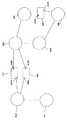
図4は、1つのネットワークから別のネットワークへのトラフィックの流れを容易にするためにネットワークを接続するようにDCSが使用される1つの例証的ルーティングの図を示す。図4は特に、ルーティング・ノード401〜406を示し、それぞれが例証的に、広帯域ネットワーク112などのネットワーク、または図1におけるネットワーク要素116のグループなどのネットワークの一部を表す。このように、ルーティング・ノード401〜406のそれぞれは例証的に、それぞれルーティング目的のために、図1におけるそれぞれポート130および134などの入力ポートおよび出力ポートを有する単一のルーティング・ノードとしてモデル化された複数のネットワーク要素を有する。ルーティング・ノード401〜406のそれぞれにより表されたネットワークは例えば、異なったプロトコルまたは速度を使用して動作することができ、そしてしたがって、DCS407、408、および409などのDCSは、トラフィックを集合、および/または分離させて、DCSにより相互接続された異なるネットワークの間の、またはそこを渡っての、そのトラフィックの伝送を容易にするように使用することができる。例えば、ルーティング・ノード402および405は、例証的速度155.52Mb/sにて動作する周知のOC−3ネットワークを表す場合があり、一方ノード403および406により表されたネットワークは、例証的に622.08Mb/sの速度にて動作する周知のOC−12ネットワークである場合がある。DCS407および408は、ノード402および403により表されたネットワークの間のデータを集合および/または分離し、そしてDCS409は、ノード405および406により表されたネットワークの間のトラフィックを集合および分離する。DCS407〜409を通る通路は通常、比較的静的な方法にて設定される。例えばノード402に関連付けられたポート407Aからノード403に関連付けられた407Bへの通路は、DCS407上で、ノード402および403により表されたネットワークの間の接続性を提供するために設定される。ポート408A/408Bおよび409A/409Bの間の接続は、それぞれノード402/403および405/406を接続するために同様に設定される。このように、当業者はDCS407〜409がそれぞれのネットワークの間の共通的なノードとして機能することを認識するだろう。 FIG. 4 shows one illustrative routing diagram in which DCS is used to connect networks to facilitate the flow of traffic from one network to another. 4 specifically shows routing nodes 401-406, each illustratively representing a portion of a network, such as a network, such as broadband network 112, or a group of
当業者が認識するように、DCS407〜409の内の任意の1つなどのDCSは、ある点においてルータまたはATMスイッチなどの、ネットワーク・スイッチと同様に機能する。しかしながら、そのようなルータ/スイッチは少なくとも部分的にはネットワークを通過するトラフィックに伴う信号方式の一機能として通常は動作し、そしてしたがってそのようなルータ/スイッチは、ネットワーク・サービス・プロバイダにより提供される特定のサービスに通常密接に結合される。通常DCSはそのような目的には使用されない。そうではなくDCSは通常は、ネットワークの上位レベルでの伝送管理に使用される。具体的には、スイッチ制御が顧客に提供されたサービスの固有の要素であり、ネットワークのレイヤ2にて使用されるプロトコルに密接に結合されているほとんどの電子通信サービスと異なって、DCSは通常、ネットワークにおけるレイヤ1(すなわちネットワークの物理層)にて設計的、および設定制御的な機構として使用される。このように、DCSは通常、ルータおよび他の型のスイッチのように、短期間にわたって切り換えを動的に変更するようには使用されない。さらに、DCSは通常、顧客からの信号方式の機能として制御されることはなく、そうではなく例えば、サービス・プロバイダの技術者によって直接制御される。またより簡単なネットワーク・スイッチと異なり、典型的なDCSは通常は、何時間かから何カ月かの期間にわたって不変の、DCSを通るネットワーク・パスおよび接続を設定することを容易にする。 As those skilled in the art will appreciate, a DCS, such as any one of DCS 407-409, functions in some respects like a network switch, such as a router or ATM switch. However, such routers / switches usually operate at least in part as a signaling function associated with traffic passing through the network, and therefore such routers / switches are provided by network service providers. Usually tightly coupled to a particular service. Usually DCS is not used for such purposes. Instead, DCS is typically used for transmission management at the upper level of the network. Specifically, switch control is an inherent element of the service provided to the customer, and unlike most electronic communication services that are tightly coupled to the protocols used at Layer 2 of the network, DCS is usually , Used as a design and configuration control mechanism at
電気通信サービス・プロバイダなどのサービス・プロバイダが、より高度な機能を消費者に提供するように努力するので、DCS407〜409や他の同様の装置によって生成されたものなどの、ネットワーク間の相互接続および接続点は、数の上でますます多くなり、かつ重要性が増大する。ネットワークのルーティングの方策を開発する場合には、これらの相互接続装置を考慮に入れねばならない。ルーティングを決定する際に、ネットワーク構成管理システムは伝統的に、DCSなどの装置を1つまたは複数の別々のルーティング・ノードとしてモデル化した。しかしながら、DCSのそのようなモデル化では、ルーティングモデルにおいてノードを通過するために必要な「ホップ(hop)」が多くなるが故に、必要なルーティング処理を増加させることを、本発明者は発見した。これは、例えば前述のルーティング図表を発生させるために必要な、時間およびオーバヘッドの両方を増大させる。したがって’187出願において記述されたように、ネットワークの第2層でのルーティング決定を簡素化することに加えて、そのネットワークの第1層でルーティング図表を簡素化することが望ましいということを、本発明者はさらに発見した。具体的には、ルーティング図表/決定をさらに簡略化するためには、ネットワークにおいてDCSを別々のノード(またはDCS上のポートに対応する複数のノード)として扱うのではなく、DCSを別様にモデル化することもまた望ましい。より詳細には、一部にはDCSおよび他の同様の装置は、構成において比較的静的であるが故に、断定的なルーティングホップとして処理することを必要とするノードの代わりに、物理ケーブルによって形成されるようなリンクとしてそのような装置を扱うことができることを本発明者は発見した。 Interconnections between networks, such as those generated by DCS 407-409 and other similar devices, as service providers such as telecommunications service providers strive to provide more advanced functionality to consumers And the number of connection points becomes more and more important in number. These interconnected devices must be taken into account when developing network routing strategies. In making routing decisions, network configuration management systems traditionally modeled devices such as DCS as one or more separate routing nodes. However, the present inventors have found that such modeling of DCS increases the required routing processing because of the more “hops” required to pass through the nodes in the routing model. . This increases, for example, both the time and overhead required to generate the aforementioned routing diagram. Thus, as described in the '187 application, in addition to simplifying routing decisions at the second layer of the network, it is desirable to simplify the routing diagram at the first layer of the network. The inventor further discovered. Specifically, to further simplify the routing diagram / decision, the DCS is modeled differently, rather than treating the DCS as separate nodes (or multiple nodes corresponding to ports on the DCS) in the network. It is also desirable to More specifically, in part, DCS and other similar devices are relatively static in configuration, so that instead of nodes that need to be treated as assertive routing hops, physical cables The inventor has discovered that such a device can be treated as a link as formed.
’187出願と関連して上で記述されたように、図1におけるネットワーク112などのネットワークにおいてネットワーク・パスを設定するに先立ち、図1におけるNCMS126などのネットワーク構成管理システムはネットワークにおけるネットワーク要素およびリンクを一覧化することとなる。これらの要素およびリンクが定義されると、NCMSはネットワークを通るトランク/回路を設定する際に使用されるべき、ルーティング・ノードおよびリンクに関するネットワーク接続形態を示す、ルーティング図表を発生させる。図5はそのようなルーティング図の簡略化された表現である。特に、ルーティング・ノード401〜406は上で図4と関連して記述されたものである。それらのルーティング・ノードのそれぞれは例えば、前述のトランク/回路を設定するために必要とされる処理オーバヘッドを削減するために高レベルで単一のルーティング・ノードとしてモデル化された複数のネットワーク要素から成る。しかしながら、図4のDCS407〜409のポートは個々のノードとしてモデル化されるのではなく、または複数のノードとしてモデル化されるのではなく、それらの例証的DCSはリンク501、502、および503としてモデル化される。リンク501、502、および503は、それぞれDCS407、408、および409を表すように、図5のルーティング図表において使用される。従って本発明の原理によると、DCSなどのクロス・コネクトは、ポートを互いに、そして他のネットワーク要素上の外部のポートに接続する様々なリンクを有する、1つまたは複数のルーティング・ノードとしてモデル化されることはない。そうではなく、そのようなクロス・コネクトは1つまたは複数のネットワークにおけるネットワーク要素の間の個別のリンクとしてモデル化される。従って、ルーティング図は大いに簡略化される。 As described above in connection with the '187 application, prior to establishing a network path in a network such as network 112 in FIG. 1, a network configuration management system such as
DCSまたは他のネットワークの構成要素が追加されたとき、または削除されたときに、NCMSが、上で記述されたようにDCSをリンクとして扱い、ネットワーク要素および要素間のリンクを一覧化することとなることを当業者は認識するだろう。具体的には、この一覧化は図3の一覧サブシステム306により行われる。この一覧化の一部として、NCMS102により管理されるネットワーク群内およびそれらの間のリンク、ノード、およびクロス・コネクトについての情報を用いて、ルーティング・リンク・テーブル314、ルーティング・ノード・テーブル316、NMS/EMS・テーブル318およびクロス・コネクト状態データベース324が更新される。したがってこの一覧化においては、クロス・コネクト状態データベースにおいてそれぞれのDCSに関する情報が更新されることとなり、そしてそれらの同じDCSがルーティング・リンク・テーブルにおけるリンクとして更新されることとなる。その結果、サービス有効化システム310がパスを設定するためにルーティング・エンジン308を呼び出したときには、そのエンジンはDCSを、DCS上のポートに対応する1つまたは複数のネットワーク・ノードではなく、設定されるべきリンクとして扱うこととなる。ネットワーク・トラフィックが特定のDCSを通過するときには、そのDCSに関連する構成および状態情報がクロス・コネクト状態データベース324から検索され、適切な宛先にトラフィックをルーティングするためにそのDCSを通るパスがどのように設定されるべきであるかを特定する。 When DCS or other network components are added or removed, NCMS treats DCS as a link as described above and lists network elements and links between elements Those skilled in the art will recognize that. Specifically, this listing is performed by the
特定のネットワークに関してネットワーク設計に柔軟性を追加し、そしてルーティング管理オーバヘッド費用を減少させるための必要性により、分散化された境界要素機能を生成するために、多くの変更が可能であり、かつ上でここに記述されたこれらの実施形態のいずれかまたはすべてを結合させることができることを当業者は認識するだろう。以上の詳細な説明は例証的かつ代表的なものであって、限定的なものではないことを理解すべきであり、かつここに開示された本発明の範囲は詳細な説明からではなく、請求の範囲から特許法で許容された範囲に従って解釈されるように判断されるべきである。ここに示されかつ記述された実施形態は本発明の原理を例証するのみであり、かつ本発明の範囲および精神から逸脱することなく様々な修正を当業者が実施することができることを理解するべきである。本発明の範囲および精神から逸脱することなく、当業者は他の様々な特徴を組み合わせて実施することができる。 The need to add flexibility to the network design for a particular network and reduce routing management overhead costs allows many changes to produce decentralized boundary element functions, and above Those skilled in the art will recognize that any or all of these embodiments described herein can be combined. It should be understood that the foregoing detailed description is exemplary and representative and is not restrictive, and that the scope of the invention disclosed herein is not from the detailed description, but is claimed. Therefore, it should be determined to be construed in accordance with the scope allowed by patent law. It should be understood that the embodiments shown and described herein are merely illustrative of the principles of the invention and that various modifications can be made by those skilled in the art without departing from the scope and spirit of the invention. It is. Those skilled in the art can implement various other features in combination without departing from the scope and spirit of the present invention.
Claims (12)
Translated fromJapanese前記少なくとも第1のネットワーク要素および前記少なくとも第2のネットワーク要素のそれぞれを、複数のルーティング・ノードおよび当該複数のルーティング・ノードを相互接続する複数のリンクを含む図表における1つまたは複数のルーティング・ノードとしてモデル化する一覧サブシステムと、
前記少なくとも第1のネットワーク要素と前記少なくとも第2のネットワーク要素との間のパスを決定するために、前記図表を使用するように適合されたルーティング・エンジンとを備え、
前記一覧サブシステムが、前記共通ネットワーク装置を前記少なくとも第1のネットワーク要素と前記少なくとも第2のネットワーク要素との間のリンクとしてモデル化し、
前記ネットワーク設定システムは、
前記複数のルーティング・ノードの相互接続のそれぞれの状態を格納するように構成されたクロス・コネクト状態データベースであって、前記状態は、サービス有効化システムが前記ルーティング・エンジンを起動して所与の2つの端点のルーティング・パスを取得し、さらに要素アダプタを呼び出して前記決定されたパスを物理的に設定することによりクロス・コネクトが設定されたかどうかを示す、クロス・コネクト状態データベースを備えることを特徴とするシステム。A network configuration system for establishing a path between at least a first network element and at least a second network element interconnected by a common network device, comprising:
One or more routing nodes in a diagram including a plurality of routing nodes and a plurality of links interconnecting the plurality of routing nodes, each of the at least first network element and the at least second network element A list subsystem that is modeled as
A routing engine adapted to use the chart to determine a path between the at least first network element and the at least second network element;
The listing subsystem models the common network device as a link between the at least first network element and the at least second network element;
The network setting system includes:
A cross-connect state database configured to store a state of each of the interconnections of the plurality of routing nodes, the state beingactivated by a service enablement system invoking the routing engine for a given Providing across-connect state database indicating whether or not a cross-connecthas been establishedby obtaining a routing path of two endpoints and further calling the element adapter to physically set the determined pathFeature system.
前記複数のネットワーク要素のうちの1つまたは複数のネットワーク要素を表すルーティング・ノードおよび前記ルーティング・ノードの間の相互接続を表すリンクの図表を生成する手段と、
前記少なくとも第1の共通ネットワーク装置を、前記第1のネットワーク要素および前記第2のネットワーク要素を表すルーティング・ノードの間のリンクとしてモデル化する手段と、
前記相互接続のそれぞれの状態を格納する手段であって、前記状態は、サービス有効化システムが前記図表を生成する手段を起動して所与の2つの端点のルーティング・パスを取得し、さらに要素アダプタを呼び出して決定されたパスを物理的に設定することによりクロス・コネクションが設定されたかどうかを示す、手段と
を備えることを特徴とするルーティング・マネージャ。A plurality of network elements in one or more networks, wherein at least a first common network device is interposed between at least a first network element and a second network element of the plurality of network elements. A routing manager for setting up a path for network traffic between
Means for generating a diagram of a routing node representing one or more of the plurality of network elements and a link representing an interconnection between the routing nodes;
Means for modeling the at least first common network device as a link between routing nodes representing the first network element and the second network element;
Means for storing a state of each of the interconnections, wherein the stateactivates a means for the service activation system to generate the chart to obtain a routing path for a given two endpoints; indicates whether the cross-connectionis setby setting a path which is determined by calling the adapter physically routing manager, characterized in that it comprises a means.
前記第1の複数のネットワーク要素のうちの少なくとも1つの第1のネットワーク要素と前記第2の複数のネットワーク要素のうちの1つの第2ネットワーク要素との間の前記デジタル・クロス・コネクトにより生成される相互接続群を決定するステップと、
前記デジタル・クロス・コネクトを、前記第1のネットワーク要素と前記第2のネットワーク要素との間のリンクとして表すステップと、
クロス・コネクト・状態データベース中に前記相互接続群のそれぞれの状態を格納するステップであって、前記状態は、サービス有効化システムがルーティング・エンジンを起動して所与の2つの端点のルーティング・パスを取得し、さらに要素アダプタを呼び出して決定されたパスを物理的に設定することによりクロス・コネクションが設定されたかどうかを示す、ステップと
を備えることを特徴とする方法。A method for routing network traffic between a first network and a second network, wherein the first network comprises a first plurality of network elements, and the second network is a second A plurality of network elements, wherein the first plurality of network elements and the second plurality of network elements are connected by digital cross connect,
Generated by the digital cross connect between at least one first network element of the first plurality of network elements and one second network element of the second plurality of network elements. Determining a set of interconnect groups;
Representing the digital cross connect as a link between the first network element and the second network element;
Storing the state of each of the interconnect groups in a cross-connect state database, wherein the state is determined bythe service activation system invoking the routing engine and routing paths at given two endpoints. how to get, it indicates whether the cross-connectionis setby physically set the determined path by calling further element adapter, characterized by comprising the stepsof.
前記第1および第2のネットワーク中の前記複数のネットワーク要素を1つまたは複数のルーティング・ノードとしてモデル化するステップと、
前記ネットワーク・リンクを、前記ルーティング・ノードを相互接続するルーティング・リンクとしてモデル化するステップと、
前記共通ネットワーク装置を、前記第1のネットワーク中の第1のルーティング・ノードを前記第2のネットワーク中の第2のルーティング・ノードに接続するルーティング・リンクとしてモデル化するステップと、
前記ルーティング・ノードの相互接続のそれぞれの状態を格納するステップであって、前記状態は、サービス有効化システムがルーティング・エンジンを起動して所与の2つの端点のルーティング・パスを取得し、さらに要素アダプタを呼び出して決定されたパスを物理的に設定することによりクロス・コネクションが設定されたかどうかを示す、ステップと
を備えることを特徴とする方法。A first network element in a first network and a second network connected via a common network device to a second network of networks each having a plurality of network elements and a plurality of network links A method for determining a path to a second network element of
Modeling the plurality of network elements in the first and second networks as one or more routing nodes;
Modeling the network link as a routing link interconnecting the routing nodes;
Modeling the common network device as a routing link connecting a first routing node in the first network to a second routing node in the second network;
Storing the state of each of the routing node interconnections, wherein the stateactivates a routing engine to obtain a routing path for a given two endpoints; It indicates whether the cross-connectionis setby setting the determined call the element adapter path physically method characterized by comprising the steps.
Applications Claiming Priority (5)
| Application Number | Priority Date | Filing Date | Title |
|---|---|---|---|
| US61460904P | 2004-09-30 | 2004-09-30 | |
| US60/614,609 | 2004-09-30 | ||
| US11/101,136 | 2005-04-07 | ||
| US11/101,136US7760664B2 (en) | 2004-09-30 | 2005-04-07 | Determining and provisioning paths in a network |
| PCT/US2005/034418WO2006110171A2 (en) | 2004-09-30 | 2005-09-28 | Determining and provisioning paths in a network |
Publications (2)
| Publication Number | Publication Date |
|---|---|
| JP2008515345A JP2008515345A (en) | 2008-05-08 |
| JP4777990B2true JP4777990B2 (en) | 2011-09-21 |
Family
ID=36098929
Family Applications (1)
| Application Number | Title | Priority Date | Filing Date |
|---|---|---|---|
| JP2007534687AExpired - Fee RelatedJP4777990B2 (en) | 2004-09-30 | 2005-09-28 | Determine and configure paths in the network |
Country Status (5)
| Country | Link |
|---|---|
| US (1) | US7760664B2 (en) |
| EP (1) | EP1797670B1 (en) |
| JP (1) | JP4777990B2 (en) |
| CA (1) | CA2581734C (en) |
| WO (1) | WO2006110171A2 (en) |
Families Citing this family (19)
| Publication number | Priority date | Publication date | Assignee | Title |
|---|---|---|---|---|
| JP2006228078A (en)* | 2005-02-21 | 2006-08-31 | Hitachi Ltd | Access management method, management computer, or computer system between multiple devices configured in a hierarchical relationship |
| US7778202B2 (en)* | 2007-06-01 | 2010-08-17 | Tellabs Operations, Inc. | Method and apparatus to provision network routes |
| CN101981844B (en)* | 2008-02-04 | 2013-09-11 | 中兴通讯股份有限公司 | Method and device for implementing source routing in resistive crossover network |
| US8271585B2 (en)* | 2010-02-10 | 2012-09-18 | Microsoft Corporation | Identifying intermediaries and potential contacts between organizations |
| US8874888B1 (en) | 2011-01-13 | 2014-10-28 | Google Inc. | Managed boot in a cloud system |
| US9135037B1 (en) | 2011-01-13 | 2015-09-15 | Google Inc. | Virtual network protocol |
| US8862743B1 (en)* | 2011-01-13 | 2014-10-14 | Google Inc. | Resource management |
| US8533796B1 (en) | 2011-03-16 | 2013-09-10 | Google Inc. | Providing application programs with access to secured resources |
| US9237087B1 (en) | 2011-03-16 | 2016-01-12 | Google Inc. | Virtual machine name resolution |
| US9063818B1 (en) | 2011-03-16 | 2015-06-23 | Google Inc. | Automated software updating based on prior activity |
| US9075979B1 (en) | 2011-08-11 | 2015-07-07 | Google Inc. | Authentication based on proximity to mobile device |
| US8966198B1 (en) | 2011-09-01 | 2015-02-24 | Google Inc. | Providing snapshots of virtual storage devices |
| US8958293B1 (en) | 2011-12-06 | 2015-02-17 | Google Inc. | Transparent load-balancing for cloud computing services |
| US8800009B1 (en) | 2011-12-30 | 2014-08-05 | Google Inc. | Virtual machine service access |
| US8983860B1 (en) | 2012-01-30 | 2015-03-17 | Google Inc. | Advertising auction system |
| US8996887B2 (en) | 2012-02-24 | 2015-03-31 | Google Inc. | Log structured volume encryption for virtual machines |
| US8677449B1 (en) | 2012-03-19 | 2014-03-18 | Google Inc. | Exposing data to virtual machines |
| CN103488651B (en)* | 2012-06-08 | 2018-12-11 | 北京千橡网景科技发展有限公司 | Method and device for obtaining relationship path between members |
| US12431964B2 (en) | 2023-04-18 | 2025-09-30 | Bank Of America Corporation | System and method for interaction system resiliency by aggregation with heterogenous communication networks |
Family Cites Families (21)
| Publication number | Priority date | Publication date | Assignee | Title |
|---|---|---|---|---|
| CA1118084A (en) | 1979-06-22 | 1982-02-09 | Edmund Szybicki | Alternate routing for a telephone system |
| US4669113A (en) | 1985-04-26 | 1987-05-26 | At&T Company | Integrated network controller for a dynamic nonhierarchical routing switching network |
| US4788421A (en) | 1985-05-15 | 1988-11-29 | Mitsubishi Denki Kabushiki Kaisha | Apparatus for controlling relative movement of an optical head to an optical disk with velocity detection |
| US5297137A (en) | 1991-01-30 | 1994-03-22 | International Business Machines Corporation | Process for routing data packets around a multi-node communications network |
| US5377262A (en) | 1991-12-30 | 1994-12-27 | At&T Corp. | Telecommunication switching system having adaptive routing switching nodes |
| US5526414A (en) | 1994-10-26 | 1996-06-11 | Northern Telecom Limited | Dynamically controlled routing using virtual nodes |
| US5764740A (en)* | 1995-07-14 | 1998-06-09 | Telefonaktiebolaget Lm Ericsson | System and method for optimal logical network capacity dimensioning with broadband traffic |
| US5864666A (en)* | 1996-12-23 | 1999-01-26 | International Business Machines Corporation | Web-based administration of IP tunneling on internet firewalls |
| SE510485C2 (en)* | 1997-02-24 | 1999-05-25 | Ericsson Telefon Ab L M | An apparatus, system and method for handling communication |
| JP3974705B2 (en)* | 1998-03-20 | 2007-09-12 | 富士通株式会社 | Network service management method |
| US6714217B2 (en) | 1998-12-18 | 2004-03-30 | Sprint Communication Company, L.P. | System and method for providing a graphical user interface to, for building, and/or for monitoring a telecommunication network |
| JP3653660B2 (en)* | 1999-01-11 | 2005-06-02 | 富士通株式会社 | Network management method and network management system |
| EP1212686A4 (en) | 1999-05-26 | 2009-04-01 | Fujitsu Ltd | ADMINISTRATION SYSTEM FOR NETWORK ELEMENTS |
| JP4110671B2 (en)* | 1999-05-27 | 2008-07-02 | 株式会社日立製作所 | Data transfer device |
| US7173912B2 (en)* | 2000-05-05 | 2007-02-06 | Fujitsu Limited | Method and system for modeling and advertising asymmetric topology of a node in a transport network |
| US6981065B1 (en)* | 2000-05-18 | 2005-12-27 | Nortel Networks Limited | Provisioning of connection through a SONET/SDH network |
| US7289456B2 (en) | 2002-04-08 | 2007-10-30 | Telcordia Technologies, Inc. | Determining and provisioning paths within a network of communication elements |
| DE60233980D1 (en)* | 2002-07-18 | 2009-11-19 | Ericsson Telefon Ab L M | Management system and method for the provision of subscription services |
| US7454428B2 (en)* | 2003-10-29 | 2008-11-18 | Oracle International Corp. | Network data model for relational database management system |
| US7577091B2 (en)* | 2004-02-04 | 2009-08-18 | Telefonaktiebolaget Lm Ericsson (Publ) | Cluster-based network provisioning |
| CN116806056B (en) | 2022-03-25 | 2024-12-13 | 华硕电脑股份有限公司 | Method and device for handling unicast and multicast semi-static scheduling deactivated state |
- 2005
- 2005-04-07USUS11/101,136patent/US7760664B2/enactiveActive
- 2005-09-28CACA2581734Apatent/CA2581734C/ennot_activeExpired - Fee Related
- 2005-09-28WOPCT/US2005/034418patent/WO2006110171A2/enactiveApplication Filing
- 2005-09-28EPEP05857725.5Apatent/EP1797670B1/ennot_activeCeased
- 2005-09-28JPJP2007534687Apatent/JP4777990B2/ennot_activeExpired - Fee Related
Also Published As
| Publication number | Publication date |
|---|---|
| CA2581734C (en) | 2012-08-28 |
| JP2008515345A (en) | 2008-05-08 |
| EP1797670A4 (en) | 2009-09-23 |
| US7760664B2 (en) | 2010-07-20 |
| US20060067236A1 (en) | 2006-03-30 |
| EP1797670A2 (en) | 2007-06-20 |
| CA2581734A1 (en) | 2006-10-19 |
| WO2006110171A2 (en) | 2006-10-19 |
| EP1797670B1 (en) | 2017-11-22 |
| WO2006110171A3 (en) | 2007-03-29 |
Similar Documents
| Publication | Publication Date | Title |
|---|---|---|
| JP4777990B2 (en) | Determine and configure paths in the network | |
| USRE43704E1 (en) | Determining and provisioning paths within a network of communication elements | |
| US9237035B2 (en) | Technique for implementing an optical/TDM virtual private network | |
| Zhang et al. | An overview of virtual private network (VPN): IP VPN and optical VPN | |
| US20020029298A1 (en) | Arrangement, a system and a method relating to management communication | |
| US7414985B1 (en) | Link aggregation | |
| JP4205953B2 (en) | Improvements in and related to communication networks | |
| GB2324223A (en) | Network management | |
| US7379457B2 (en) | Technique for implementing a virtual private optical switched transport network using virtual private optical/TDM cross-connect technology | |
| CN100361449C (en) | An optical network management system and an end-to-end service realization method | |
| Xu et al. | Generalized MPLS-based distributed control architecture for automatically switched transport networks | |
| JP4751292B2 (en) | Method, computer software program and system for automatically selecting time slots in time division multiplexing | |
| WO2006121462A2 (en) | Systems and methods for endoscope integrity testing | |
| Jajszczyk | The ASON approach to the control plane for optical networks | |
| Bosco et al. | Evolution of the wide area network | |
| KR100337142B1 (en) | QTHR : QoS/Traffic Parameter Based Hierarchical Routing technique | |
| JP4235562B2 (en) | Communication network | |
| EP1045536A1 (en) | Optical fiber communication network device | |
| Lu | A top-down operations model for ADSL and ATM based access networks | |
| Cao et al. | Optical internetworking models and standards directions | |
| Youssef | Structured Backbone Design of CNs | |
| Hulikunte | An analysis of the architecture of Internet protocol (IP) over optics implementations | |
| SECTOR et al. | ITU-Tg. 8080/Y. 1304 | |
| GB2465589A (en) | Integrated Multilayer Network Restoration using Hybrid Network Elements. |
Legal Events
| Date | Code | Title | Description |
|---|---|---|---|
| A131 | Notification of reasons for refusal | Free format text:JAPANESE INTERMEDIATE CODE: A131 Effective date:20090731 | |
| A521 | Request for written amendment filed | Free format text:JAPANESE INTERMEDIATE CODE: A523 Effective date:20091030 | |
| A131 | Notification of reasons for refusal | Free format text:JAPANESE INTERMEDIATE CODE: A131 Effective date:20100507 | |
| A711 | Notification of change in applicant | Free format text:JAPANESE INTERMEDIATE CODE: A711 Effective date:20100618 | |
| A521 | Request for written amendment filed | Free format text:JAPANESE INTERMEDIATE CODE: A523 Effective date:20100805 | |
| A02 | Decision of refusal | Free format text:JAPANESE INTERMEDIATE CODE: A02 Effective date:20101210 | |
| A521 | Request for written amendment filed | Free format text:JAPANESE INTERMEDIATE CODE: A523 Effective date:20110411 | |
| RD13 | Notification of appointment of power of sub attorney | Free format text:JAPANESE INTERMEDIATE CODE: A7433 Effective date:20110412 | |
| A521 | Request for written amendment filed | Free format text:JAPANESE INTERMEDIATE CODE: A821 Effective date:20110412 | |
| A911 | Transfer to examiner for re-examination before appeal (zenchi) | Free format text:JAPANESE INTERMEDIATE CODE: A911 Effective date:20110506 | |
| TRDD | Decision of grant or rejection written | ||
| A01 | Written decision to grant a patent or to grant a registration (utility model) | Free format text:JAPANESE INTERMEDIATE CODE: A01 Effective date:20110603 | |
| A01 | Written decision to grant a patent or to grant a registration (utility model) | Free format text:JAPANESE INTERMEDIATE CODE: A01 | |
| A61 | First payment of annual fees (during grant procedure) | Free format text:JAPANESE INTERMEDIATE CODE: A61 Effective date:20110630 | |
| R150 | Certificate of patent or registration of utility model | Ref document number:4777990 Country of ref document:JP Free format text:JAPANESE INTERMEDIATE CODE: R150 Free format text:JAPANESE INTERMEDIATE CODE: R150 | |
| FPAY | Renewal fee payment (event date is renewal date of database) | Free format text:PAYMENT UNTIL: 20140708 Year of fee payment:3 | |
| FPAY | Renewal fee payment (event date is renewal date of database) | Free format text:PAYMENT UNTIL: 20140708 Year of fee payment:3 | |
| S111 | Request for change of ownership or part of ownership | Free format text:JAPANESE INTERMEDIATE CODE: R313113 | |
| FPAY | Renewal fee payment (event date is renewal date of database) | Free format text:PAYMENT UNTIL: 20140708 Year of fee payment:3 | |
| R350 | Written notification of registration of transfer | Free format text:JAPANESE INTERMEDIATE CODE: R350 | |
| R250 | Receipt of annual fees | Free format text:JAPANESE INTERMEDIATE CODE: R250 | |
| R250 | Receipt of annual fees | Free format text:JAPANESE INTERMEDIATE CODE: R250 | |
| R250 | Receipt of annual fees | Free format text:JAPANESE INTERMEDIATE CODE: R250 | |
| R250 | Receipt of annual fees | Free format text:JAPANESE INTERMEDIATE CODE: R250 | |
| R250 | Receipt of annual fees | Free format text:JAPANESE INTERMEDIATE CODE: R250 | |
| R250 | Receipt of annual fees | Free format text:JAPANESE INTERMEDIATE CODE: R250 | |
| R250 | Receipt of annual fees | Free format text:JAPANESE INTERMEDIATE CODE: R250 | |
| R250 | Receipt of annual fees | Free format text:JAPANESE INTERMEDIATE CODE: R250 | |
| LAPS | Cancellation because of no payment of annual fees |