JP4774059B2 - Electrical exhaust gas recirculation valve - Google Patents
Electrical exhaust gas recirculation valveDownload PDFInfo
- Publication number
- JP4774059B2 JP4774059B2JP2007552478AJP2007552478AJP4774059B2JP 4774059 B2JP4774059 B2JP 4774059B2JP 2007552478 AJP2007552478 AJP 2007552478AJP 2007552478 AJP2007552478 AJP 2007552478AJP 4774059 B2JP4774059 B2JP 4774059B2
- Authority
- JP
- Japan
- Prior art keywords
- actuator
- armature
- valve
- valve housing
- lumen
- Prior art date
- Legal status (The legal status is an assumption and is not a legal conclusion. Google has not performed a legal analysis and makes no representation as to the accuracy of the status listed.)
- Expired - Fee Related
Links
- 238000000034methodMethods0.000claimsdescription15
- 230000004907fluxEffects0.000claimsdescription6
- 238000005452bendingMethods0.000claimsdescription4
- 230000008569processEffects0.000claimsdescription2
- 210000001215vaginaAnatomy0.000claims1
- 230000013011matingEffects0.000description10
- 230000007246mechanismEffects0.000description9
- 239000000463materialSubstances0.000description6
- 230000002093peripheral effectEffects0.000description4
- 238000007789sealingMethods0.000description4
- 238000004519manufacturing processMethods0.000description3
- 230000000712assemblyEffects0.000description2
- 238000000429assemblyMethods0.000description2
- 238000000576coating methodMethods0.000description2
- 238000007373indentationMethods0.000description2
- 239000000203mixtureSubstances0.000description2
- -1polytetrafluoroethylenePolymers0.000description2
- 229920001343polytetrafluoroethylenePolymers0.000description2
- 239000004810polytetrafluoroethyleneSubstances0.000description2
- 230000009467reductionEffects0.000description2
- 230000004044responseEffects0.000description2
- 230000004888barrier functionEffects0.000description1
- 239000011248coating agentSubstances0.000description1
- 238000004891communicationMethods0.000description1
- 150000001875compoundsChemical class0.000description1
- 238000010276constructionMethods0.000description1
- 238000013016dampingMethods0.000description1
- 230000007423decreaseEffects0.000description1
- 238000013461designMethods0.000description1
- 230000014759maintenance of locationEffects0.000description1
- 238000005259measurementMethods0.000description1
- 238000012986modificationMethods0.000description1
- 230000004048modificationEffects0.000description1
- 238000012544monitoring processMethods0.000description1
- 238000000465mouldingMethods0.000description1
- 238000003825pressingMethods0.000description1
- 238000004080punchingMethods0.000description1
Images


Classifications
- F—MECHANICAL ENGINEERING; LIGHTING; HEATING; WEAPONS; BLASTING
- F16—ENGINEERING ELEMENTS AND UNITS; GENERAL MEASURES FOR PRODUCING AND MAINTAINING EFFECTIVE FUNCTIONING OF MACHINES OR INSTALLATIONS; THERMAL INSULATION IN GENERAL
- F16K—VALVES; TAPS; COCKS; ACTUATING-FLOATS; DEVICES FOR VENTING OR AERATING
- F16K31/00—Actuating devices; Operating means; Releasing devices
- F16K31/02—Actuating devices; Operating means; Releasing devices electric; magnetic
- F16K31/06—Actuating devices; Operating means; Releasing devices electric; magnetic using a magnet, e.g. diaphragm valves, cutting off by means of a liquid
- F16K31/0686—Braking, pressure equilibration, shock absorbing
- F16K31/0696—Shock absorbing, e.g. using a dash-pot
- F—MECHANICAL ENGINEERING; LIGHTING; HEATING; WEAPONS; BLASTING
- F02—COMBUSTION ENGINES; HOT-GAS OR COMBUSTION-PRODUCT ENGINE PLANTS
- F02M—SUPPLYING COMBUSTION ENGINES IN GENERAL WITH COMBUSTIBLE MIXTURES OR CONSTITUENTS THEREOF
- F02M26/00—Engine-pertinent apparatus for adding exhaust gases to combustion-air, main fuel or fuel-air mixture, e.g. by exhaust gas recirculation [EGR] systems
- F02M26/45—Sensors specially adapted for EGR systems
- F02M26/48—EGR valve position sensors
- F—MECHANICAL ENGINEERING; LIGHTING; HEATING; WEAPONS; BLASTING
- F02—COMBUSTION ENGINES; HOT-GAS OR COMBUSTION-PRODUCT ENGINE PLANTS
- F02M—SUPPLYING COMBUSTION ENGINES IN GENERAL WITH COMBUSTIBLE MIXTURES OR CONSTITUENTS THEREOF
- F02M26/00—Engine-pertinent apparatus for adding exhaust gases to combustion-air, main fuel or fuel-air mixture, e.g. by exhaust gas recirculation [EGR] systems
- F02M26/52—Systems for actuating EGR valves
- F02M26/53—Systems for actuating EGR valves using electric actuators, e.g. solenoids
- F—MECHANICAL ENGINEERING; LIGHTING; HEATING; WEAPONS; BLASTING
- F02—COMBUSTION ENGINES; HOT-GAS OR COMBUSTION-PRODUCT ENGINE PLANTS
- F02M—SUPPLYING COMBUSTION ENGINES IN GENERAL WITH COMBUSTIBLE MIXTURES OR CONSTITUENTS THEREOF
- F02M26/00—Engine-pertinent apparatus for adding exhaust gases to combustion-air, main fuel or fuel-air mixture, e.g. by exhaust gas recirculation [EGR] systems
- F02M26/65—Constructional details of EGR valves
- F02M26/66—Lift valves, e.g. poppet valves
- F02M26/67—Pintles; Spindles; Springs; Bearings; Sealings; Connections to actuators
- F—MECHANICAL ENGINEERING; LIGHTING; HEATING; WEAPONS; BLASTING
- F02—COMBUSTION ENGINES; HOT-GAS OR COMBUSTION-PRODUCT ENGINE PLANTS
- F02M—SUPPLYING COMBUSTION ENGINES IN GENERAL WITH COMBUSTIBLE MIXTURES OR CONSTITUENTS THEREOF
- F02M26/00—Engine-pertinent apparatus for adding exhaust gases to combustion-air, main fuel or fuel-air mixture, e.g. by exhaust gas recirculation [EGR] systems
- F02M26/65—Constructional details of EGR valves
- F02M26/72—Housings
- F—MECHANICAL ENGINEERING; LIGHTING; HEATING; WEAPONS; BLASTING
- F16—ENGINEERING ELEMENTS AND UNITS; GENERAL MEASURES FOR PRODUCING AND MAINTAINING EFFECTIVE FUNCTIONING OF MACHINES OR INSTALLATIONS; THERMAL INSULATION IN GENERAL
- F16K—VALVES; TAPS; COCKS; ACTUATING-FLOATS; DEVICES FOR VENTING OR AERATING
- F16K31/00—Actuating devices; Operating means; Releasing devices
- F16K31/02—Actuating devices; Operating means; Releasing devices electric; magnetic
- F16K31/06—Actuating devices; Operating means; Releasing devices electric; magnetic using a magnet, e.g. diaphragm valves, cutting off by means of a liquid
- F16K31/0675—Electromagnet aspects, e.g. electric supply therefor
- F—MECHANICAL ENGINEERING; LIGHTING; HEATING; WEAPONS; BLASTING
- F16—ENGINEERING ELEMENTS AND UNITS; GENERAL MEASURES FOR PRODUCING AND MAINTAINING EFFECTIVE FUNCTIONING OF MACHINES OR INSTALLATIONS; THERMAL INSULATION IN GENERAL
- F16K—VALVES; TAPS; COCKS; ACTUATING-FLOATS; DEVICES FOR VENTING OR AERATING
- F16K31/00—Actuating devices; Operating means; Releasing devices
- F16K31/02—Actuating devices; Operating means; Releasing devices electric; magnetic
- F16K31/06—Actuating devices; Operating means; Releasing devices electric; magnetic using a magnet, e.g. diaphragm valves, cutting off by means of a liquid
- F16K31/0686—Braking, pressure equilibration, shock absorbing
- F16K31/0689—Braking of the valve element
- F—MECHANICAL ENGINEERING; LIGHTING; HEATING; WEAPONS; BLASTING
- F16—ENGINEERING ELEMENTS AND UNITS; GENERAL MEASURES FOR PRODUCING AND MAINTAINING EFFECTIVE FUNCTIONING OF MACHINES OR INSTALLATIONS; THERMAL INSULATION IN GENERAL
- F16K—VALVES; TAPS; COCKS; ACTUATING-FLOATS; DEVICES FOR VENTING OR AERATING
- F16K31/00—Actuating devices; Operating means; Releasing devices
- F16K31/02—Actuating devices; Operating means; Releasing devices electric; magnetic
- F16K31/06—Actuating devices; Operating means; Releasing devices electric; magnetic using a magnet, e.g. diaphragm valves, cutting off by means of a liquid
- F16K31/0686—Braking, pressure equilibration, shock absorbing
- F16K31/0693—Pressure equilibration of the armature
- F—MECHANICAL ENGINEERING; LIGHTING; HEATING; WEAPONS; BLASTING
- F02—COMBUSTION ENGINES; HOT-GAS OR COMBUSTION-PRODUCT ENGINE PLANTS
- F02M—SUPPLYING COMBUSTION ENGINES IN GENERAL WITH COMBUSTIBLE MIXTURES OR CONSTITUENTS THEREOF
- F02M26/00—Engine-pertinent apparatus for adding exhaust gases to combustion-air, main fuel or fuel-air mixture, e.g. by exhaust gas recirculation [EGR] systems
- F02M26/11—Manufacture or assembly of EGR systems; Materials or coatings specially adapted for EGR systems
Landscapes
- Engineering & Computer Science (AREA)
- General Engineering & Computer Science (AREA)
- Mechanical Engineering (AREA)
- Chemical & Material Sciences (AREA)
- Combustion & Propulsion (AREA)
- Analytical Chemistry (AREA)
- Physics & Mathematics (AREA)
- Electromagnetism (AREA)
- Magnetically Actuated Valves (AREA)
- Exhaust-Gas Circulating Devices (AREA)
Description
Translated fromJapanese(関連出願の相互参照)
本出願は、2005年2月1日に提出された米国仮出願第60/648,829号に対する優先権を主張するものである。(Cross-reference of related applications)
This application claims priority to US Provisional Application No. 60 / 648,829 filed Feb. 1, 2005.
本発明は、一般に、電気的排気ガス再循環(EGR)弁及びアクチュエータに関するものである。本発明は、特にEGR弁及び多種多様な弁に適合する単一アクチュエータを利用するアクチュエータと、EGR弁及びアクチュエータの組み立て方法とに関する。 The present invention relates generally to electrical exhaust gas recirculation (EGR) valves and actuators. The present invention relates to an actuator that utilizes a single actuator that is particularly compatible with EGR valves and a wide variety of valves, and a method for assembling EGR valves and actuators.
電気的排気ガス再循環弁は、ソレノイドを利用して、エンジン吸気装置への排気ガスの流入を制御する弁に動力を供給する。ソレノイドの一般的な働きは既知のところであり、発生磁界に応答したアーマチュアの比例動作を含んでいる。磁界は、コイルにより発生し、上部及び下部ステータによって導かれて、アーマチュアを動かす所望の磁力を供給する。アーマチュアの動作は、コイルに供給される電流に関連しているので、所定の電流を加えると、アーマチュアの所期の動作が生じ、この結果、更に弁が所望の量だけ開く。このため、ある特定用途のために製造した各ソレノイドは、ある特定の電流入力に関し、定義された、期待される方法で機能するのが望ましい。こうした部品間における一貫性のため、許容差の厳しい高価な部品が必要になる場合が多い。 The electrical exhaust gas recirculation valve uses a solenoid to power a valve that controls the flow of exhaust gas into the engine intake system. The general operation of the solenoid is known and includes the proportional movement of the armature in response to the generated magnetic field. The magnetic field is generated by the coil and is guided by the upper and lower stators to provide the desired magnetic force to move the armature. Since the armature movement is related to the current supplied to the coil, application of a predetermined current results in the desired armature movement, which further opens the valve by the desired amount. For this reason, each solenoid manufactured for a particular application should function in a defined and expected manner for a particular current input. This consistency between parts often requires expensive parts with tight tolerances.
コスト削減が全ての自動車部品供給業者及び製造業者の永続的目標であるため、高価な部品の利用は、弁アセンブリ全体のコストを増大する不都合がある。更に、コスト削減の要望に加えて、性能要件も更に要求が厳しくなる。 The use of expensive parts has the disadvantage of increasing the overall cost of the valve assembly, as cost reduction is a permanent goal of all automotive parts suppliers and manufacturers. Furthermore, in addition to the demand for cost reduction, the performance requirements become more demanding.
従って、製造の容易な部品及び方法を利用し、同時に、所望の性能の制御精度及び持続性を保つ、EGR弁及びアクチュエータを開発することが望まれている。 Accordingly, it is desirable to develop EGR valves and actuators that utilize parts and methods that are easy to manufacture, while at the same time maintaining the control accuracy and sustainability of the desired performance.
本発明による排気ガス再循環(EGR)弁の一例には、単一のアクチュエータを様々な弁アセンブリに利用できるように、弁アセンブリに取付け可能なアクチュエータが含まれている。アクチュエータは、較正プラグを介して弁アセンブリに連結される。較正プラグは、所望の弁素子位置に対するアクチュエータのアーマチュア位置の較正を可能にする。 One example of an exhaust gas recirculation (EGR) valve in accordance with the present invention includes an actuator that can be attached to a valve assembly so that a single actuator can be utilized for various valve assemblies. The actuator is coupled to the valve assembly via a calibration plug. The calibration plug allows calibration of the armature position of the actuator relative to the desired valve element position.
この弁アセンブリは、第1の内腔と第2の内腔を形成する弁ハウジングを含む。吸気口及び排気口が第2の内腔と通じ、排気ガスの通路を形成している。第2の内腔を通る排気ガス流が、ピントルによって計量される。ピントルは、第2の内腔内において軸受によって案内され、打抜き加工によって製作された弁座を密封する。 The valve assembly includes a valve housing that defines a first lumen and a second lumen. An intake port and an exhaust port communicate with the second lumen to form an exhaust gas passage. The exhaust gas flow through the second lumen is metered by a pintle. The pintle is guided by a bearing in the second lumen and seals the valve seat produced by stamping.
このピントルは、軸受を通り第1の内腔に入り込む第2の端部で、較正プラグに取付けられている。弁ハウジングは、アクチュエータを固定する取付け面を含む、上部嵌め合い部分を含んでいる。弁アセンブリは、上部嵌め合い部分が標準構造として保たれ、他方弁ハウジングの他の領域は特定用途向け嵌め合い要件に適合するよう修正されるので、アクチュエータの再設計なしに、特定用途向け要件に備えるよう修正できる。 The pintle is attached to the calibration plug at a second end that passes through the bearing and into the first lumen. The valve housing includes an upper mating portion that includes a mounting surface for securing the actuator. The valve assembly maintains the top mating portion as a standard structure, while other areas of the valve housing are modified to meet application-specific mating requirements, so that application requirements can be met without actuator redesign. Can be modified to prepare.
アクチュエータ及びハウジングセンブリには、製作公差に適応し、弁性能を調整する2つの可調整機能を含んでいる。第1に軸とアーマチュアとの間の接合面であり、第2にピントルと較正プラグとの間の圧入である。これら調整機能は、両方共、調整及び較正を施し、アクチュエータの動作を弁アセンブリの所望の動作に合わせる。軸に取付けたアーマチュア及び較正プラグにより生ずる嵌め合い及び較正機能により、多種多様な弁ハウジング構造にアクチュエータが利用可能となる。 The actuator and housing assembly includes two adjustable functions to accommodate manufacturing tolerances and adjust valve performance. The first is the interface between the shaft and the armature, and the second is the press fit between the pintle and the calibration plug. Both of these adjustment functions provide adjustment and calibration to tailor the operation of the actuator to the desired operation of the valve assembly. The mating and calibration function produced by the armature and calibration plug attached to the shaft makes the actuator available for a wide variety of valve housing structures.
本発明の以上の特徴及びその他の特徴を、以下の説明と図面から明らかにする。 These and other features of the present invention will become apparent from the following description and drawings.
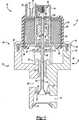
図1を参照すると、排気ガス再循環(EGR)弁10は、単一設計のアクチュエータを様々な弁アセンブリに利用可能とすべく、弁アセンブリ14に取付け可能なアクチュエータ12を含んでいる。アクチュエータ12は、較正プラグ36との接合面を介してピントル30の動作を制御する。較正プラグ36は、アクチュエータ12内におけるピントル30とアーマチュア軸58との相対位置を較正する。較正プラグ36は、ピントル30の内腔33内の所望の深さまで押し込まれる。アーマチュア軸58が、較正プラグ36のドーム31に接触して、ピントル30の位置を制御する。 Referring to FIG. 1, an exhaust gas recirculation (EGR) valve 10 includes an actuator 12 that can be attached to a valve assembly 14 to enable a single design actuator to be used for various valve assemblies. The actuator 12 controls the operation of the
この弁アセンブリ14は、第1の内腔20と第2の内腔22を形成する弁ハウジング16を含む。吸気口24と排気口26が第2の内腔22に通じていて、排気ガスの通路を形成している。第2の内腔22を通る排気ガス流は、ピントル30により計量される。ピントル30は、第2の内腔22内で軸受34により案内される。軸受34は、材料費を削減すべく、薄壁を含んでいる。 The valve assembly 14 includes a
ピントル30は、弁座28を密封するシーリングヘッド32を含む。弁座28は、打抜き加工で製作され、ピントル30のシーリングヘッド32と協働する開口部を含む。 The
このピントル30は、較正プラグ36に取付けられており、軸受34を経て第1の内腔20に入り込む。較正プラグ36は、バネ保持体38に取付けられている。バネ保持体38は、バネ40を保持する機構を含む打抜き加工部品である。バネ40は、弁座28に対してピントル30を通常の閉位置に保持する。バネ保持体38には、バネ40の端部を受けて保持するための周辺圧痕機構を含む。 The
弁ハウジング16は、全体を95で示す上部嵌め合い部分を含んでいる。この上部嵌め合い部分95は、アクチュエータ12が固定される取付け表面25と、較正プラグ36、バネ40及びバネ保持体38を含む第1の内腔20を含む。弁アセンブリ14は、アクチュエータ12の再設計を必要とせずに、特定用途向け要件に備えるように修正できる。上部嵌め合い部分95は、標準的構造に保ち、他方弁ハウジング16の他の領域は、特定用途向け嵌め合い要件に備えるように修正する。 The
弁ハウジング16は、第2の内腔22の下方端を密封するためのエンドプラグ42を含む。エンドプラグ42は、外側にバイアスを加えられ、弁ハウジング16の内部表面に押し付けられるバネタブ機構を含んでいる。エンドプラグ42の外側へのバイアスにより、弁ハウジング16内にエンドプラグ42を保持するのに望ましい保持力が生ずる。 The
アクチュエータ12は、内腔66を形成するコイルアセンブリ50を含んでいる。上部ステータ68と下部ステータ74が、内腔66内に延び、部分的に所望の磁気回路を形成する。上部ステータ68は、下部ステータ74から間隔をあけて配置され、所望の空隙を形成している。この空隙により、コイルアセンブリ50に対する電流の供給に応じた、内腔66内でのアーマチュア56の動作が可能になる。 Actuator 12 includes a coil assembly 50 that defines a lumen 66. Upper stator 68 and
コイルアセンブリ50は、コイルアセンブリ50からコネクタポケット54内に入り込む端子52を含んでいる。コネクタポケット54によって、既知のコントローラ(不図示)と電気的に通じるようになる。 The coil assembly 50 includes
アーマチュア56は、軸58に支持されている。更に、軸58は、上部ブッシュ62及び下部ブッシュ64によって案内される。上部ブッシュ62は、上部ステータ68の内腔部70に圧入される。下部ブッシュ64は、外部ブッシュ65に圧入され、外部ブッシュ65は、同様に、下部ステータ74の内腔部76に圧入される。アーマチュア56は、軸58に支持されているので、コイルアセンブリ50の内腔66は支持面ではない。更に、上部ステータ68の内腔70及び下部ステータ74の内腔76は、軸58の支持面ではない。アーマチュア56は、軸58に支持されているので、非磁性スリーブによってコイルアセンブリ50内においてアーマチュア56の滑り運動を支援する必要がなくなる。 The armature 56 is supported on the
アーマチュア56は、更に、所望の磁束特性をもたらす機構を含むフラックスエンド60を含んでいる。アーマチュア56が、下部ステータ74の磁束特性を調整するのに望ましい機構を含むので、下部ステータ74の構成の大幅な単純化が可能である。 The armature 56 further includes a flux end 60 that includes a mechanism that provides the desired magnetic flux characteristics. Since the armature 56 includes a mechanism that is desirable for adjusting the magnetic flux characteristics of the
下部ステータ74は、弁ハウジング16の取付け面25と協働して、アクチュエータ12を弁アセンブリ14に取付ける取付け板78も含んでいる。取付け板78は、弁ハウジング16と係合する締め金具80用の開口部を含む。アクチュエータ12及び弁ハウジング16の最上部95は、アクチュエータ12を多種多様な弁ハウジング構造に利用できるように、可能性のある多くの弁構造に共通している。 The
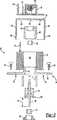
引き続き図1を参照しながら、図2を参照すると、較正プラグ36によってアクチュエータ12と弁アセンブリ14との接合面が生ずる。軸58は、較正プラグ36のドーム31に接触し、ピントル内腔33は、ステム35を受ける。ピントル30のピントル内腔33内へのステム35の嵌め込みは、溶接37または他の永久固定方法を実施できる迄、所望の位置を保持するための軽い圧入である。最初に、較正プラグ36をピントル30内に所望の深さ39迄圧入する。深さ39は、アクチュエータ12に所望の較正を施すべく調整する。軸58は、較正プラグ36のドーム31に接触するが、取付けてはいない。バネ40によって、軸58とドーム31のバイアス接触を保持する。 With continued reference to FIG. 1 and with reference to FIG. 2, the
引き続き図1と2を参照しつつ図3を見ると、アクチュエータ12は、軸58の端部とアーマチュア56との間の長さ59を調整することで別個に較正される。従って、アクチュエータ12の動作を、長さ59の調整によって、様々な磁力要件に備えるように調整できる。更に、弁アセンブリ14は、深さ39を調整し、弁の動作を所望の条件に合わせることで較正できる。複合調整により、特定用途向け要件を満たすことが可能なアクチュエータ12及び弁アセンブリ14の動作が可能になる。 Looking at FIG. 3 with continued reference to FIGS. 1 and 2, the actuator 12 is separately calibrated by adjusting the
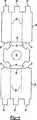
図3〜5は、アクチュエータ12を分解図で例示する。アクチュエータ12の組み立ては、ストラップシェル82に上部ステータ68を圧入することから始まる。ストラップシェル82は、打抜き加工部品であり、上部ステータ68を圧入する開口部85を含む。開口部85は、ストラップシェル82と上部ステータ68との間の磁気接触を保つコンプライアント機構83を含んでいる。上部ステータ68は、同様に打抜き加工部品であり、内腔70を含んでいる。一旦上部ステータ68をストラップシェル82に圧入すると、上部ステータ68がコイルアセンブリ50の内腔66内に延びるように、コイル50をスライドさせて、上部ステータ68に嵌められる。 3-5 illustrate the actuator 12 in an exploded view. The assembly of the actuator 12 begins by press-fitting the upper stator 68 into the
図4と5を参照すると、ストラップシェル82は、ほぼU字形をなすように曲げたフィンガ86を含む。ストラップシェル82のフィンガ86は、コイルアセンブリ50の周りでほぼ円筒形状をなしている。フィンガ86は、これを曲げ部96に沿って90°曲げると八角形の一部を形成する、2つの45°の曲げ部89を含んでいる。従って、ストラップシェル82は、同様に2つの折り曲げフィンガ86を曲げ部89に沿って折り曲げることで、全体で八角形を形成する。 With reference to FIGS. 4 and 5, the
フィンガ86を2つの45°の曲げ部89に沿って折り曲げると、3区域が生じる。2つの外側の区域は、ストラップシェル82の上部近くにタブ87を含む。フィンガ86を曲げ部96に沿って折り曲げると、タブ87は上部区域のスロット94に入り込む。曲げ部89によって形成される3つの区域は、各々、下部ステータ74のスロット75内に収容されるタブ84を含んでいる。 Bending
再度図3を参照すると、下部ステータ74がコイルアセンブリ50に挿入され、タブ84がスロット75を貫通する。次に、タブ84は、下部ステータ74をストラップシェル82にそして更にコイルアセンブリ50の周りに固定すべく、折り曲げられる。一旦下部ステータ74がストラップシェル82に固定されると、センサアセンブリ90がコイルアセンブリ50に組み付けられる。センサアセンブリ90は、コネクタポケット54を形成するハウジング55を含んでいる。コネクタポケット54は、コイル50の端子52のための開口部を含み、更にコネクタポケット54は、センサアセンブリ90からの端子51も含んでいる。センサアセンブリ90は、コイルアセンブリ50内における軸58の、従って、アーマチュア56の線形位置の測定及び監視を可能にする。 Referring again to FIG. 3, the
センサアセンブリ90を取付けた後、アセンブリ全体に、硬化可能な混合物により外被を形成する。硬化可能な混合物は、アクチュエータアセンブリの諸部分を封止して、アクチュエータの動作環境から部品を保護する。更に、外被によって、センサアセンブリ90をアクチュエータ12に固定する。外被形成プロセス中、公差の緩やかな部品を、幾つかの機構によってモールド内で厳格に整合のとれた状態に保つ。各接合面に、遭遇する成形圧力に対応し、同時に、所望の磁束特性をもたらすのに必要な関係を維持するためのコンプライアンスが、各種部品に生じる。硬化可能材料によって、特殊なコーティング又はシールを用いることなく、構成要素に有効なバリヤを施す。 After mounting sensor assembly 90, the entire assembly is enveloped with a curable mixture. The curable mixture seals portions of the actuator assembly and protects the part from the operating environment of the actuator. Further, the sensor assembly 90 is fixed to the actuator 12 by a jacket. During the envelope forming process, loose tolerance parts are kept in tight alignment within the mold by several mechanisms. At each joint surface, compliance occurs in the various parts to accommodate the molding pressures encountered and at the same time maintain the relationships necessary to provide the desired magnetic flux characteristics. The curable material provides an effective barrier to the component without the use of special coatings or seals.
アセンブリの外被を形成した後、上部及び下部ブッシュ62、64を取付ける。上部及び下部ブッシュ62、64に、軸58の移動に対する摩擦を減らすため、ポリテトラフルオロエチレンのライニングを施す。ポリテトラフルオロエチレンでライニングしたブッシュ62、64は、更に、コイルアセンブリ50内の軸58、従って、アーマチュア56の整合を可能にする。アーマチュア56と軸58を内腔66に挿入した後、まず下部ブッシュ64を外部ブッシュ65に組み付け、次に、外部ブッシュ65を、下部ステータ74の内腔部分76に圧入する。 After forming the outer casing of the assembly, the upper and lower bushings 62, 64 are installed. The upper and lower bushings 62, 64 are lined with polytetrafluoroethylene to reduce friction against movement of the
軸に取付けたアーマチュア56によって、内腔66内の低摩擦コーティング又は非磁性スリーブは不要となる。軸58の端部に対するアーマチュア56の距離59を、所望の磁気特性が得られるように決定する。内腔66内にアーマチュア56を組み付けた後、下部ブッシュ64を内腔76に圧入する。アクチュエータ12は、ほぼ完成し、弁ハウジング16への取付け準備が整う。アクチュエータ12は、高振動条件下で、所望のアーマチュア位置を保持するための追加バネ67も含んでいる。追加バネ67は、アーマチュアと上部ステータ68の間、又は所望の振動減衰性能をもたらすべく決定した他の位置に配置できる。更に、標準バネ67の概略を例示しているが、例えば皿バネワッシャ等の、他の既知のバイアス部材も使用できる。 The armature 56 attached to the shaft eliminates the need for a low friction coating or non-magnetic sleeve in the lumen 66. The
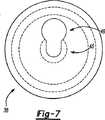
図6及び7は、弁アセンブリ14を分解図で示す。弁ハウジング16は、アクチュエータ12の嵌め合い面を形成する共通の上部95を含んでいる。弁アセンブリ14は、内腔20と22の間の内腔23に軸受34を圧入することで組み立てられる。軸受34は、ピントル30を案内し、材料を減らすため、比較的薄い壁を含む。軸受34は、所望の耐久特性と共に、ピントルの移動に対する所望の低摩擦抵抗をもたらすように決定した材料で製作する。軸受34の費用は、一般に、材料の体積又は重量により決まる故、小さな又は壁の薄い軸受34は、利用する材料の総量の減少に伴い費用を削減する。 6 and 7 show the valve assembly 14 in an exploded view. The
次に、弁座28を弁ハウジング16に圧入する。弁座28は、ピントルヘッド32のための開口部を含む、打抜き加工部品である。弁座28を圧入し、次に、所望の位置を保持し、移動を阻止すべく、かしめ付ける。 Next, the valve seat 28 is press-fitted into the
軸受34及び弁座を弁ハウジング16に組み付けると、ピントル30が弁ハウジング16に挿入され、較正プラグ36がピントル30に取付けられる(図2)。ステム35を、ピントル内腔33内に収容し、適切な公差の部品により施される軽い圧入によって保持する。軽い圧入によって、溶接37等のより永久的な取付け及び固定方法に先立つ、所望の嵌め合い及び保持が可能となる。 When the bearing 34 and the valve seat are assembled to the
較正プラグ36は、バネ保持体38に形成されたキースロット46にはまる周辺グルーブ48を含んでいる。バネ保持体38は、バネ40の端部を保持する周辺圧痕を含む打ち抜き加工部品である。周辺グルーブ48は、キースロット46に収まって、較正プラグ36をバネ保持体38に接続する。バネ保持体38は、較正プラグ36が載っている戻り止め45によって所定位置に保持される。バネ40は、ピントル30にバイアス力を加えるため、バネ保持体38と弁ハウジング16の間に組み付けられている。 The
ハウジング16において、排気口26は片側に配置されており、従って、エンドプラグ42は、弁ハウジング16の端部に挿入されている。エンドプラグ42は、弁ハウジング16の内表面に対し外向きの力を加えるように構成した打ち抜き加工部品である。外側への力によって、エンドプラグ42が所定位置に保持され、エンドプラグ42を弁ハウジング16に固定する二次動作が不要となる。次に、アクチュエータ12を、軸58が較正プラグ36のドーム31に接するように、弁ハウジング16に取付ける。 In the
アクチュエータ12及び弁アセンブリ14は、製造公差に適応し、それを考慮に入れた2つの可調整機能を含んでいる。即ち、ピントル30へのステム35の圧入と、軸58へのアーマチュア56の圧入である。2つの調整機能により、弁アセンブリ14のアクチュエータ12の動作を適応させるため、調整及び較正を施す。軸に取付けたアーマチュア56によって、所望の電流入力に関連した所望の出力を維持すべく、アクチュエータ12の磁気特性を適応させ、調整する。軸58と較正プラグ36との突合せ接合面により、多種多様な弁ハウジング構造を備えたアクチュエータ12の利用が可能になる。 The actuator 12 and valve assembly 14 include two adjustable functions that accommodate and take into account manufacturing tolerances. That is, press fitting of the
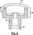
図8と9は、異なる下方機構を含む、弁ハウジング代替例96、98を示す。各弁ハウジング96、98は、アクチュエータ12に対応する、共通の最上部95及び取付け面25を含んでいる。従って、多種多様な弁ハウジング構造に対応すべく、アクチュエータ12を利用し、調整を加えて、多種多様な用途のための共通部品を得ることができる。 Figures 8 and 9 show
本発明の望ましい実施形態について開示してきたが、当該技術の通常の技術者には、幾つかの修正が本発明の範囲内に入ることが明らかであろう。そのため、付属の請求の範囲を検討することによって、本発明の真の範囲及び内容を判断するのが望ましい。 While preferred embodiments of the invention have been disclosed, it will be apparent to those skilled in the art that several modifications are within the scope of the invention. For this reason, it is desirable to determine the true scope and content of the present invention by examining the appended claims.
10 EGR弁、 12 アクチュエータ、14 弁アセンブリ、16 弁ハウジング、20、22 弁ハウジングの内腔、24 吸気口、25 取付け表面、26 排気口、28 弁座、30 ピントル、31 ドーム、32 シーリングヘッド、33 ピントル内腔、34 軸受、35 ステム、36 較正プラグ、38 バネ保持体、40 バネ、42 エンドプラグ、50 コイルアセンブリ、54 コネクタポケット、56 アーマチュア、58 軸、62 上部ブッシュ、64 下部ブッシュ、66 コイルアセンブリ内腔、67 追加バネ、68 上部ステータ、70 上部ステータ内腔、74 下部ステータ、75 スロット、76 下部ステータ内腔、80 締め金具、82 ストラップシェル、83 コンプライアント機構、84 タブ、85 ストラップシェル開口部、86 フィンガ、87 タブ、89 曲げ部、90 センサアセンブリ、95 上部嵌め合い部分、96、98 弁ハウジング 10 EGR valve, 12 Actuator, 14 Valve assembly, 16 Valve housing, 20, 22 Valve housing lumen, 24 Inlet, 25 Mounting surface, 26 Exhaust, 28 Valve seat, 30 Pintle, 31 Dome, 32 Sealing head, 33 pintle lumen, 34 bearing, 35 stem, 36 calibration plug, 38 spring holder, 40 spring, 42 end plug, 50 coil assembly, 54 connector pocket, 56 armature, 58 shaft, 62 upper bush, 64 lower bush, 66 Coil assembly lumen, 67 Additional spring, 68 Upper stator, 70 Upper stator lumen, 74 Lower stator, 75 slots, 76 Lower stator lumen, 80 Fastener, 82 Strap shell, 83 Compliant mechanism, 84 Tab, 85 Trap shell opening, 86 finger, 87 tab, 89 bend, 90 sensor assembly, 95 top mating, 96, 98 valve housing
Claims (7)
Translated fromJapanesea)弁ハウジングを通るガス流路を形成する工程、
b)前記弁ハウジング内に弁素子を支持する工程、
c)前記弁ハウジングにアクチュエータを取付ける工程および
d)前記アクチュエータの動作によって前記弁素子の動作を較正するのに望ましい関連配向をなすように、前記弁素子に対して前記アクチュエータのアーマチュアを位置決めする工程を含み、
アーマチュアを位置決めする工程において、
弁素子の内膣内に較正プラグのステムを圧入して位置決めした状態で較正を実行した後、
ステムを弁素子に永久的に固定する
ことを特徴とする方法。A method of assembling an exhaust gas recirculation device,
a) forming a gas flow path through the valve housing;
b) supporting a valve element in the valve housing;
c) attaching an actuator to the valve housing; and d) positioning the actuator armature with respect to the valve element such that the operation of the actuator provides the desired relative orientation to calibrate the operation of the valve element. Including
In the process of positioning the armature,
After performing calibration with the stem of the calibration plug pressed into the vagina of the valve element and positioned,
A method characterized in that thestem is permanently fixed to the valve element .
前記第1及び第2のストラップの各々に配置されたタブを前記第2の表面の上に曲げる工程を含むことを特徴とする請求項5記載の方法。Wrapping the magnetic flux strap around the coil assembly, bending the first and second straps from a first surface to a second surface around the coil assembly;
6. The method of claim5 , comprising bending a tab disposed on each of the first and second straps over the second surface.
Applications Claiming Priority (3)
| Application Number | Priority Date | Filing Date | Title |
|---|---|---|---|
| US64882905P | 2005-02-01 | 2005-02-01 | |
| US60/648,829 | 2005-02-01 | ||
| PCT/CA2006/000124WO2006081653A1 (en) | 2005-02-01 | 2006-02-01 | Cost optimized electric egr valve |
Publications (2)
| Publication Number | Publication Date |
|---|---|
| JP2009526153A JP2009526153A (en) | 2009-07-16 |
| JP4774059B2true JP4774059B2 (en) | 2011-09-14 |
Family
ID=36776893
Family Applications (1)
| Application Number | Title | Priority Date | Filing Date |
|---|---|---|---|
| JP2007552478AExpired - Fee RelatedJP4774059B2 (en) | 2005-02-01 | 2006-02-01 | Electrical exhaust gas recirculation valve |
Country Status (5)
| Country | Link |
|---|---|
| US (1) | US20060185654A1 (en) |
| EP (1) | EP1861607A4 (en) |
| JP (1) | JP4774059B2 (en) |
| KR (1) | KR100863193B1 (en) |
| WO (1) | WO2006081653A1 (en) |
Families Citing this family (11)
| Publication number | Priority date | Publication date | Assignee | Title |
|---|---|---|---|---|
| EP2143931A3 (en)* | 2008-07-10 | 2012-09-05 | Hirschmann Automotive GmbH | AGR valve system |
| US8746514B2 (en)* | 2009-02-12 | 2014-06-10 | Nordson Corporation | Dispensing device with valve assembly having continuously smooth transition between tip and stem |
| CN103181154A (en) | 2010-10-29 | 2013-06-26 | 加利福尼亚大学董事会 | Mobile phone microscope apparatus and method for imaging |
| DE102014109247B4 (en) | 2014-07-02 | 2019-06-19 | Pierburg Gmbh | Modular control valve |
| US10591081B2 (en)* | 2016-04-01 | 2020-03-17 | Emerson Electric Co. | Solenoid coil including bobbin with moisture barrier |
| US10871242B2 (en) | 2016-06-23 | 2020-12-22 | Rain Bird Corporation | Solenoid and method of manufacture |
| US10980120B2 (en) | 2017-06-15 | 2021-04-13 | Rain Bird Corporation | Compact printed circuit board |
| US11503782B2 (en) | 2018-04-11 | 2022-11-22 | Rain Bird Corporation | Smart drip irrigation emitter |
| WO2021149019A1 (en)* | 2020-01-24 | 2021-07-29 | Padmini Vna Mechatronics Pvt. Ltd. | An improved idle air control valve with enhanced efficiency |
| WO2021149018A1 (en)* | 2020-01-24 | 2021-07-29 | Padmini Vna Mechatronics Pvt. Ltd. | An improved idle air control valve |
| US11721465B2 (en) | 2020-04-24 | 2023-08-08 | Rain Bird Corporation | Solenoid apparatus and methods of assembly |
Citations (2)
| Publication number | Priority date | Publication date | Assignee | Title |
|---|---|---|---|---|
| JPS52102930A (en)* | 1976-02-24 | 1977-08-29 | Toyota Motor Corp | Exhaust-gas-circulation control valve system for automobile |
| JP2001515267A (en)* | 1997-09-03 | 2001-09-18 | シーメンス カナダ リミテッド | Electromagnetically operated exhaust gas recirculation valve with excellent space utilization efficiency |
Family Cites Families (63)
| Publication number | Priority date | Publication date | Assignee | Title |
|---|---|---|---|---|
| US1861885A (en)* | 1931-04-21 | 1932-06-07 | Louis Haven | Valve for internal combustion engines |
| US1984751A (en)* | 1932-11-28 | 1934-12-18 | Thompson Prod Inc | Method of making hollow valves |
| US4022237A (en)* | 1974-02-28 | 1977-05-10 | The Bendix Corporation | Exhaust gas recirculation flow control system |
| US4178666A (en)* | 1976-02-24 | 1979-12-18 | Toyota Jidosha Kogyo Kabushiki Kaisha | Method of assembling a valve device for an exhaust gas recirculation system of an internal combustion engine |
| ATE25872T1 (en)* | 1980-11-07 | 1987-03-15 | David Baram | VALVE. |
| US4990880A (en)* | 1989-07-24 | 1991-02-05 | Alcatel Na, Inc. | Transformer clip |
| US5161223A (en)* | 1989-10-23 | 1992-11-03 | International Business Machines Corporation | Resumeable batch query for processing time consuming queries in an object oriented database management system |
| US5761655A (en)* | 1990-06-06 | 1998-06-02 | Alphatronix, Inc. | Image file storage and retrieval system |
| US5110087A (en)* | 1990-06-25 | 1992-05-05 | Borg-Warner Automotive Electronic & Mechanical Systems Corporation | Variable force solenoid hydraulic control valve |
| DE4039351A1 (en)* | 1990-12-10 | 1992-06-11 | Pierburg Gmbh | ELECTROMAGNETIC CONTROL VALVE FOR EXHAUST GAS RECIRCULATION |
| US5460146A (en)* | 1994-01-12 | 1995-10-24 | Robertshaw Controls Company | Solenoid activated exhaust gas recirculation valve |
| US5945987A (en)* | 1995-05-05 | 1999-08-31 | Microsoft Corporation | Interactive entertainment network system and method for providing short sets of preview video trailers |
| US5593132A (en)* | 1995-06-30 | 1997-01-14 | Siemens Electric Limited | Electromagnetic actuator arrangement for engine control valve |
| US6202060B1 (en)* | 1996-10-29 | 2001-03-13 | Bao Q. Tran | Data management system |
| US5960776A (en)* | 1996-11-21 | 1999-10-05 | Siemens Canada Limited | Exhaust gas recirculation valve having a centered solenoid assembly and floating valve mechanism |
| US6385600B1 (en)* | 1997-04-03 | 2002-05-07 | At&T Corp. | System and method for searching on a computer using an evidence set |
| US5901690A (en)* | 1997-09-03 | 1999-05-11 | Siemens Canada Limited | Electromagnetic actuated exhaust gas recirculation valve |
| US6239802B1 (en)* | 1997-09-15 | 2001-05-29 | International Business Machines Corporation | File menu option for making file templates from pre-existing files |
| US5961045A (en)* | 1997-09-25 | 1999-10-05 | Caterpillar Inc. | Control valve having a solenoid with a permanent magnet for a fuel injector |
| US6061692A (en)* | 1997-11-04 | 2000-05-09 | Microsoft Corporation | System and method for administering a meta database as an integral component of an information server |
| US6189520B1 (en)* | 1998-05-26 | 2001-02-20 | Siemens Canada Limited | Integration of sensor, actuator, and regulator valve in an emission control module |
| WO1999061775A1 (en)* | 1998-05-27 | 1999-12-02 | Mitsubishi Denki Kabushiki Kaisha | Exhaust gas reflux valve |
| JP3591317B2 (en)* | 1998-08-17 | 2004-11-17 | トヨタ自動車株式会社 | Exhaust gas recirculation valve forced drive for internal combustion engine |
| US7039637B2 (en)* | 1998-12-31 | 2006-05-02 | International Business Machines Corporation | System and method for evaluating characters in an inputted search string against a character table bank comprising a predetermined number of columns that correspond to a plurality of pre-determined candidate character sets in order to provide enhanced full text search |
| US6182646B1 (en)* | 1999-03-11 | 2001-02-06 | Borgwarner Inc. | Electromechanically actuated solenoid exhaust gas recirculation valve |
| JP3494590B2 (en)* | 1999-06-18 | 2004-02-09 | 富士通株式会社 | Transmission / reception system and transmission device |
| JP3476007B2 (en)* | 1999-09-10 | 2003-12-10 | インターナショナル・ビジネス・マシーンズ・コーポレーション | Recognition word registration method, speech recognition method, speech recognition device, storage medium storing software product for registration of recognition word, storage medium storing software product for speech recognition |
| US6691125B1 (en)* | 1999-11-17 | 2004-02-10 | Serena Software, Inc. | Method and apparatus for converting files stored on a mainframe computer for use by a client computer |
| US6732088B1 (en)* | 1999-12-14 | 2004-05-04 | Xerox Corporation | Collaborative searching by query induction |
| US6686938B1 (en)* | 2000-01-05 | 2004-02-03 | Apple Computer, Inc. | Method and system for providing an embedded application toolbar |
| WO2001052118A2 (en)* | 2000-01-14 | 2001-07-19 | Saba Software, Inc. | Information server |
| US6449627B1 (en)* | 2000-01-21 | 2002-09-10 | International Business Machines Corp. | Volume management method and system for a compilation of content |
| US6604542B1 (en)* | 2000-02-24 | 2003-08-12 | Delphi Technologies, Inc. | Modular exhaust gas recirculation valve |
| US6633867B1 (en)* | 2000-04-05 | 2003-10-14 | International Business Machines Corporation | System and method for providing a session query within the context of a dynamic search result set |
| US20020019749A1 (en)* | 2000-06-27 | 2002-02-14 | Steven Becker | Method and apparatus for facilitating delivery of medical services |
| DE10033412B4 (en)* | 2000-07-08 | 2012-05-24 | Khs Corpoplast Gmbh | Device for blow molding containers |
| US6390079B1 (en)* | 2000-08-21 | 2002-05-21 | Siemens Canada Limited | Exhaust gas recirculation valve including cam linkage for converting constant angular motion to non-linear motion |
| US6915507B1 (en)* | 2000-11-21 | 2005-07-05 | Microsoft Corporation | Extensible architecture for project-development systems |
| US7103666B2 (en)* | 2001-01-12 | 2006-09-05 | Siemens Medical Solutions Health Services Corporation | System and user interface supporting concurrent application operation and interoperability |
| US20030005464A1 (en)* | 2001-05-01 | 2003-01-02 | Amicas, Inc. | System and method for repository storage of private data on a network for direct client access |
| US7308439B2 (en)* | 2001-06-06 | 2007-12-11 | Hyperthink Llc | Methods and systems for user activated automated searching |
| US20020188616A1 (en)* | 2001-06-07 | 2002-12-12 | Chinnici Roberto R. | Database access bridge system and process |
| US6439214B1 (en)* | 2001-08-14 | 2002-08-27 | Siemens Automotive Inc. | Linear solenoid automotive emission control valve |
| US6915305B2 (en)* | 2001-08-15 | 2005-07-05 | International Business Machines Corporation | Restructuring view maintenance system and method |
| KR100429705B1 (en)* | 2001-08-29 | 2004-05-04 | 주식회사 윌칸 | The can-receptacle possibility carrying plural stratum structure |
| JP2003157259A (en)* | 2001-09-05 | 2003-05-30 | Fuji Xerox Co Ltd | Information retrieval system |
| US6874001B2 (en)* | 2001-10-05 | 2005-03-29 | International Business Machines Corporation | Method of maintaining data consistency in a loose transaction model |
| US6474320B1 (en)* | 2001-10-05 | 2002-11-05 | Siemens Automotive Inc. | Linear electric EGR valve with damped movement |
| US6644622B2 (en)* | 2001-11-14 | 2003-11-11 | Siemens Vdo Automotive Inc. | Emission control valve having a robust solenoid actuator |
| EP1476824A4 (en)* | 2002-01-15 | 2007-02-21 | Network Appliance Inc | Active file change notification |
| US7302435B2 (en)* | 2002-03-29 | 2007-11-27 | Sony Corporation | Media storage and management system and process |
| US20040117374A1 (en)* | 2002-12-16 | 2004-06-17 | Hung Lup Cheong Patrick | Customized design portfolio integrating IP libraries and technology documents |
| US7386529B2 (en)* | 2002-12-19 | 2008-06-10 | Mathon Systems, Inc. | System and method for managing content with event driven actions to facilitate workflow and other features |
| US20040205075A1 (en)* | 2003-01-17 | 2004-10-14 | Laturner Robert R. | System and method for directing content entry |
| US9448860B2 (en)* | 2003-03-21 | 2016-09-20 | Oracle America, Inc. | Method and architecture for providing data-change alerts to external applications via a push service |
| US20050080807A1 (en)* | 2003-10-12 | 2005-04-14 | Microsoft Corporation | Extensible creation and editing of integrated collections |
| US6728729B1 (en)* | 2003-04-25 | 2004-04-27 | Apple Computer, Inc. | Accessing media across networks |
| US20050020043A1 (en)* | 2003-07-25 | 2005-01-27 | Jiun-Ren Lai | Methods for reducing cell pitch in semiconductor devices |
| US7840892B2 (en)* | 2003-08-29 | 2010-11-23 | Nokia Corporation | Organization and maintenance of images using metadata |
| US7634742B2 (en)* | 2004-04-07 | 2009-12-15 | Adobe Systems Incorporated | Graphical user interface buttons and toolbars |
| US7213022B2 (en)* | 2004-04-29 | 2007-05-01 | Filenet Corporation | Enterprise content management network-attached system |
| US20060004693A1 (en)* | 2004-05-18 | 2006-01-05 | General Electric Company | Graphical user interface for exploring databases |
| US7836044B2 (en)* | 2004-06-22 | 2010-11-16 | Google Inc. | Anticipated query generation and processing in a search engine |
- 2006
- 2006-02-01JPJP2007552478Apatent/JP4774059B2/ennot_activeExpired - Fee Related
- 2006-02-01WOPCT/CA2006/000124patent/WO2006081653A1/enactiveApplication Filing
- 2006-02-01KRKR1020077017813Apatent/KR100863193B1/ennot_activeExpired - Fee Related
- 2006-02-01USUS11/344,925patent/US20060185654A1/ennot_activeAbandoned
- 2006-02-01EPEP06705090Apatent/EP1861607A4/ennot_activeWithdrawn
Patent Citations (2)
| Publication number | Priority date | Publication date | Assignee | Title |
|---|---|---|---|---|
| JPS52102930A (en)* | 1976-02-24 | 1977-08-29 | Toyota Motor Corp | Exhaust-gas-circulation control valve system for automobile |
| JP2001515267A (en)* | 1997-09-03 | 2001-09-18 | シーメンス カナダ リミテッド | Electromagnetically operated exhaust gas recirculation valve with excellent space utilization efficiency |
Also Published As
| Publication number | Publication date |
|---|---|
| KR100863193B1 (en) | 2008-10-13 |
| KR20080048984A (en) | 2008-06-03 |
| EP1861607A4 (en) | 2012-05-02 |
| JP2009526153A (en) | 2009-07-16 |
| US20060185654A1 (en) | 2006-08-24 |
| EP1861607A1 (en) | 2007-12-05 |
| WO2006081653A1 (en) | 2006-08-10 |
Similar Documents
| Publication | Publication Date | Title |
|---|---|---|
| JP4774059B2 (en) | Electrical exhaust gas recirculation valve | |
| KR101602599B1 (en) | Solenoid | |
| KR101176645B1 (en) | Solenoid operated valve and method of making same | |
| US20100127197A1 (en) | Pressure-regulating valve | |
| EP1092854A2 (en) | Intake air controller for internal combustion engine and manufacturing the same | |
| KR20010103145A (en) | Throttle device for internal-combustion engine | |
| US11867309B2 (en) | Throttle valve device and method for magnetizing the same | |
| US11092086B2 (en) | Throttle valve device | |
| US20030089873A1 (en) | Emission control valve having a robust solenoid actuator | |
| WO2002061314A1 (en) | Solenoid valve | |
| CN112443695B (en) | Throttle valve device | |
| JP6203044B2 (en) | Intake control valve assembly structure and assembly method | |
| JP4627114B2 (en) | Solenoid valve | |
| JPH1113604A (en) | Solenoid air control valve | |
| JP2004293675A (en) | Control valve and manufacturing method for the same | |
| JP4627116B2 (en) | Solenoid valve | |
| JP2007502520A (en) | Electrical terminal | |
| JP2007263302A (en) | Mounting structure of solenoid valve | |
| JP5412330B2 (en) | hydraulic unit | |
| JP2002305109A (en) | Electromagnetic device | |
| JP3660135B2 (en) | Valve drive fixing structure | |
| JP5104186B2 (en) | Pressure sensor integrated solenoid valve and brake fluid pressure control device using the same | |
| US20030140907A1 (en) | Flexible circuit connection for moving coil of an automotive emission control valve | |
| JP2008082430A (en) | Solenoid valve | |
| JP2002310323A (en) | Three-way solenoid valve |
Legal Events
| Date | Code | Title | Description |
|---|---|---|---|
| A521 | Request for written amendment filed | Free format text:JAPANESE INTERMEDIATE CODE: A523 Effective date:20091022 | |
| A131 | Notification of reasons for refusal | Free format text:JAPANESE INTERMEDIATE CODE: A131 Effective date:20100525 | |
| A601 | Written request for extension of time | Free format text:JAPANESE INTERMEDIATE CODE: A601 Effective date:20100825 | |
| A602 | Written permission of extension of time | Free format text:JAPANESE INTERMEDIATE CODE: A602 Effective date:20100901 | |
| A601 | Written request for extension of time | Free format text:JAPANESE INTERMEDIATE CODE: A601 Effective date:20100927 | |
| A602 | Written permission of extension of time | Free format text:JAPANESE INTERMEDIATE CODE: A602 Effective date:20101007 | |
| A521 | Request for written amendment filed | Free format text:JAPANESE INTERMEDIATE CODE: A523 Effective date:20101022 | |
| A02 | Decision of refusal | Free format text:JAPANESE INTERMEDIATE CODE: A02 Effective date:20101116 | |
| A521 | Request for written amendment filed | Free format text:JAPANESE INTERMEDIATE CODE: A523 Effective date:20110315 | |
| A911 | Transfer to examiner for re-examination before appeal (zenchi) | Free format text:JAPANESE INTERMEDIATE CODE: A911 Effective date:20110509 | |
| A01 | Written decision to grant a patent or to grant a registration (utility model) | Free format text:JAPANESE INTERMEDIATE CODE: A01 Effective date:20110607 | |
| A01 | Written decision to grant a patent or to grant a registration (utility model) | Free format text:JAPANESE INTERMEDIATE CODE: A01 | |
| A61 | First payment of annual fees (during grant procedure) | Free format text:JAPANESE INTERMEDIATE CODE: A61 Effective date:20110624 | |
| FPAY | Renewal fee payment (event date is renewal date of database) | Free format text:PAYMENT UNTIL: 20140701 Year of fee payment:3 | |
| R150 | Certificate of patent or registration of utility model | Free format text:JAPANESE INTERMEDIATE CODE: R150 | |
| LAPS | Cancellation because of no payment of annual fees |