JP4771180B2 - Battery pack and battery pack control system - Google Patents
Battery pack and battery pack control systemDownload PDFInfo
- Publication number
- JP4771180B2 JP4771180B2JP2008219452AJP2008219452AJP4771180B2JP 4771180 B2JP4771180 B2JP 4771180B2JP 2008219452 AJP2008219452 AJP 2008219452AJP 2008219452 AJP2008219452 AJP 2008219452AJP 4771180 B2JP4771180 B2JP 4771180B2
- Authority
- JP
- Japan
- Prior art keywords
- assembled battery
- bypass circuit
- battery
- voltage value
- voltage
- Prior art date
- Legal status (The legal status is an assumption and is not a legal conclusion. Google has not performed a legal analysis and makes no representation as to the accuracy of the status listed.)
- Active
Links
Images


Classifications
- H—ELECTRICITY
- H01—ELECTRIC ELEMENTS
- H01M—PROCESSES OR MEANS, e.g. BATTERIES, FOR THE DIRECT CONVERSION OF CHEMICAL ENERGY INTO ELECTRICAL ENERGY
- H01M10/00—Secondary cells; Manufacture thereof
- H01M10/42—Methods or arrangements for servicing or maintenance of secondary cells or secondary half-cells
- H01M10/44—Methods for charging or discharging
- Y—GENERAL TAGGING OF NEW TECHNOLOGICAL DEVELOPMENTS; GENERAL TAGGING OF CROSS-SECTIONAL TECHNOLOGIES SPANNING OVER SEVERAL SECTIONS OF THE IPC; TECHNICAL SUBJECTS COVERED BY FORMER USPC CROSS-REFERENCE ART COLLECTIONS [XRACs] AND DIGESTS
- Y02—TECHNOLOGIES OR APPLICATIONS FOR MITIGATION OR ADAPTATION AGAINST CLIMATE CHANGE
- Y02E—REDUCTION OF GREENHOUSE GAS [GHG] EMISSIONS, RELATED TO ENERGY GENERATION, TRANSMISSION OR DISTRIBUTION
- Y02E60/00—Enabling technologies; Technologies with a potential or indirect contribution to GHG emissions mitigation
- Y02E60/10—Energy storage using batteries
Landscapes
- Engineering & Computer Science (AREA)
- Manufacturing & Machinery (AREA)
- Chemical & Material Sciences (AREA)
- Chemical Kinetics & Catalysis (AREA)
- Electrochemistry (AREA)
- General Chemical & Material Sciences (AREA)
- Charge And Discharge Circuits For Batteries Or The Like (AREA)
- Secondary Cells (AREA)
- Protection Of Static Devices (AREA)
Description
Translated fromJapanese本発明は、組電池およびその制御システムに関する。詳しくは、複数個の二次電池(セル)が直列に接続されて構成されている組電池の充放電(特に充電)を制御するシステムに関する。 The present invention relates to an assembled battery and a control system thereof. Specifically, the present invention relates to a system for controlling charging / discharging (particularly charging) of an assembled battery configured by connecting a plurality of secondary batteries (cells) in series.
リチウムイオン電池、ニッケル水素電池その他の二次電池を単電池セルとし、該単電池セルを複数個直列に接続して構成される組電池(assembled battery、バッテリー或いはバッテリーパックともいう。)は高出力が得られる電源として、ハイブリッドカー等の車両の搭載用電源、或いは、パソコンおよび携帯通信機器の電源として重要性が高まっている。特に、軽量で高エネルギー密度が得られるリチウムイオン電池を単電池セルとして複数直列に接続して構成される組電池は、車両搭載用高出力電源として好ましく用いられるものとして期待されている。
ところで、モーター駆動用電源として車両に搭載されるこの種の組電池の充放電を制御するシステムでは、所定の時期(例えばブレーキ作動時)に当該組電池に対して行われる充電処理の際に当該組電池に対して過充電が起こらないように種々の方策がとられている。
例えば、特許文献1には、組電池を構成する複数の単電池セルの各々にバイパス回路としてツェナーダイオードが並列に接続された構成の組電池制御装置が開示されている。引用文献1には、かかる構成の制御装置によって組電池充電時に当該ツェナーダイオードのツェナー電圧以上の電圧が各単電池セルに印加されることを防止することができる旨記載されている。同様に、特許文献2及び特許文献3にも直列接続される複数の単電池セルの各々にツェナーダイオード(定電圧ダイオード)が並列に接続された構成の組電池(蓄電池)が開示されている。
また、上述の特許文献1には、上記バイパス回路に加えてさらに過電圧検出回路として上記バイパス回路を構成する第1のツェナーダイオードとはツェナー電圧が異なる第2のツェナーダイオード及び発光ダイオードが組電池を構成する複数の単電池セルの各々に並列に接続された構成の組電池制御装置が開示されている。かかる構成の制御装置によれば、上記バイパス回路によって単電池セル毎の充電容量をほぼ均一にすることができるとともに、上記過電圧検出回路によって過電圧状態の単電池セルを表示し得る旨記載されている。An assembled battery (also called an assembled battery, also called a battery or a battery pack) that has a single battery cell as a lithium ion battery, nickel metal hydride battery, or other secondary battery connected in series has a high output. As a power source that can be obtained, it is becoming increasingly important as a power source for mounting a vehicle such as a hybrid car or a power source for personal computers and portable communication devices. In particular, an assembled battery configured by connecting a plurality of lithium ion batteries that are lightweight and have high energy density as a single battery cell in series is expected to be preferably used as a high-output power source for mounting on a vehicle.
By the way, in a system for controlling charging / discharging of this type of assembled battery mounted on a vehicle as a motor driving power source, the charging is performed on the assembled battery at a predetermined time (for example, when the brake is operated). Various measures are taken to prevent overcharging of the assembled battery.
For example,
In addition, in the above-mentioned
しかしながら、上記特許文献1〜3に記載されるような、組電池を構成する個々の電池セルに対して一つ乃至二つのツェナーダイオードをそれぞれ並列に接続する回路構成では、充電時に何らかの原因で所定の上限電圧を超える高い電圧が単電池セルに印加されるような状態が生じた場合に、そのことにより当該単電池セル(延いては組電池全体)に影響が生じることを確実に防止するにはまだ十分とはいえない。特に、単電池セルがリチウムイオン電池(特に非水電解液型リチウムイオン電池)である組電池の場合には、過充電状態に至って負極にリチウムが析出するような不具合が発生することを未然に防止することを確実に実現するフェイルセーフ機能が求められる。 However, in a circuit configuration in which one or two Zener diodes are connected in parallel to individual battery cells constituting an assembled battery as described in
本発明は、かかる組電池の充電状態の制御に関する従来の課題を解決すべく創出されたものであり、その一つの目的は、充電時に過充電状態を引き起こすような高い電圧が組電池を構成する単電池セルに印加されるような状態が生じた際にも、そのことにより組電池(及び組電池を構成する単電池セル)に悪影響が生じるのを確実に防止することのできるフェイルセーフ機能を備える組電池ならびに組電池の充放電(特に充電)を制御するシステムを提供することである。 The present invention was created to solve the conventional problems related to the control of the state of charge of such an assembled battery, and one object thereof is that a high voltage that causes an overcharged state during charging constitutes the assembled battery. A fail-safe function that can reliably prevent adverse effects on the battery pack (and the battery cells that make up the battery pack) when a condition occurs that is applied to the battery cell. An assembled battery and a system for controlling charging / discharging (particularly charging) of the assembled battery are provided.
上記目的を達成するべく本発明によって提供される一つの組電池は、単電池セルとしての複数の二次電池が直列に接続されて構成される組電池であって、上記複数の二次電池の直列接続に対して充電時に逆方向接続となる向きで並列に接続されたツェナーダイオードを含む第1バイパス回路と、上記二次電池および上記ツェナーダイオードに対して並列に接続されたバリスタを含む第2バイパス回路とを備えている。そして、上記ツェナーダイオードのツェナー電圧は、当該組電池の規定最大充電電圧(即ち単電池セルが過充電とならないように予め定められている充電時の最大許容入力電圧値)よりも高い所定の電圧値に設定されている第1電圧値が組電池に印可されたときに上記第1バイパス回路が通電されるように決定されており、且つ、上記バリスタのバリスタ電圧は、上記第1電圧値と等しいか又はそれよりも高い所定の電圧値に設定されている第2電圧値が組電池に印可されたときに上記第2バイパス回路が通電されるように決定されていることを特徴とする。 In order to achieve the above object, one assembled battery provided by the present invention is an assembled battery in which a plurality of secondary batteries as single battery cells are connected in series, wherein the plurality of secondary batteries A first bypass circuit including a Zener diode connected in parallel in a direction that is reversely connected when charging with respect to the series connection, and a second including a varistor connected in parallel to the secondary battery and the Zener diode. And a bypass circuit. The Zener voltage of the Zener diode is a predetermined voltage higher than the specified maximum charging voltage of the battery pack (that is, the maximum allowable input voltage value at the time of charging that is determined in advance so that the single battery cell is not overcharged). When the first voltage value set to the value is applied to the assembled battery, it is determined that the first bypass circuit is energized, and the varistor voltage of the varistor is equal to the first voltage value. It is determined that the second bypass circuit is energized when a second voltage value set to be equal to or higher than a predetermined voltage value is applied to the assembled battery.
ここで開示される組電池では、所定の第1電圧値に基づいて設定されたツェナー電圧値を有するツェナーダイオード(定電圧ダイオード)を含む第1バイパス回路が複数の二次電池(単電池セル)の直列接続(直列回路)に対して並列に形成されていることに加えて、さらに第2バイパス回路として上記二次電池および上記ツェナーダイオードに対して並列に接続されたバリスタを含む第2バイパス回路を備える。そして、本構成の組電池では、当該第2バイパス回路に含まれるバリスタのバリスタ電圧(即ちバリスタ端子間に電流(例えば基準電流:1mA)が流れ始めたときの端子間電圧をいう。)が上記第1電圧値と同等か又はそれよりもやや大きい第2電圧値に基づいて設定されている。即ち、充電時に何らかの要因で組電池に印可される異常電圧値として把握され得る第1電圧V1と第2電圧V2とは、V1≦V2の関係である。典型的にはV1<V2の関係にある。In the assembled battery disclosed herein, a first bypass circuit including a Zener diode (constant voltage diode) having a Zener voltage value set based on a predetermined first voltage value includes a plurality of secondary batteries (single battery cells). A second bypass circuit including a varistor connected in parallel to the secondary battery and the zener diode as a second bypass circuit, in addition to being formed in parallel to the series connection (series circuit) of Is provided. In the assembled battery of this configuration, the varistor voltage of the varistor included in the second bypass circuit (that is, the inter-terminal voltage when current (for example, reference current: 1 mA) starts flowing between the varistor terminals) is described above. It is set based on a second voltage value that is equal to or slightly larger than the first voltage value. That is, the first voltage V1 and the second voltage V2 that can be grasped as an abnormal voltage value applied to the assembled battery for some reason during charging have a relationship of V1 ≦ V2 . Typically, V1 <V2 .
かかる構成の結果、ここで開示される組電池によると、所定の第1電圧値よりも低い通常の入力充電電圧での充電処理が従来の組電池と同様に実行されるとともに、イレギュラーに何らかの原因で所定の規定最大充電電圧値よりも高い電圧、即ち第1電圧V1以上の高電圧が組電池に印加されるような状態が生じた場合には、ツェナー電圧が第1電圧V1に基づいて設定されたツェナーダイオードを含む第1バイパス回路に電流が流れることにより、直列接続された二次電池の過充電を防止することができる。さらに、何らかの原因でより高い電圧、即ち第2電圧V2以上の電圧が組電池に印加されるような状態(典型的には1秒以下のような瞬間的な過電圧入力状態)が生じた際には、上記V1≦V2(好ましくはV1<V2)の関係にある第2電圧V2に基づいてバリスタ電圧が設定されている第2バイパス回路のバリスタが短絡して当該第2バイパス回路に高電圧がバイパスされ(即ち電流が第2バイパス回路に流れ)、結果、直列接続された二次電池を過充電から保護することができる。As a result of such a configuration, according to the assembled battery disclosed herein, the charging process at the normal input charging voltage lower than the predetermined first voltage value is performed in the same manner as the conventional assembled battery, and irregularly, a voltage higher than a predetermined specified maximum charging voltage value due, that is, when the first voltages V1 or more high voltage has occurred condition as applied to the battery pack, the Zener voltage is first voltages V1 Since the current flows through the first bypass circuit including the Zener diode set based on the overcharge, the secondary batteries connected in series can be prevented from being overcharged. Furthermore, when a higher voltage for some reason, that state as a second voltage V2 or more voltage is applied to the assembled battery (typically instantaneous overvoltage input state, such as one second or less in) occurs The second varistor of the second bypass circuit in which the varistor voltage is set based on the second voltage V2 having the relationship of V1 ≦ V2 (preferably V1 <V2 ) is short-circuited. A high voltage is bypassed to the bypass circuit (ie, current flows to the second bypass circuit), and as a result, the secondary batteries connected in series can be protected from overcharging.
ここで開示される組電池の好ましい一態様では、上記複数の二次電池はリチウムイオン電池である。この態様において、好ましくは、上記第1バイパス回路に含まれるツェナーダイオードのツェナー電圧及び上記第2バイパス回路に含まれるバリスタのバリスタ電圧は、該ツェナーダイオードやバリスタと回路構成上の並列関係にあるリチウムイオン電池の個々の規定最大充電電圧値の合計(例えば、規定最大充電電圧値が4.1Vである50個のリチウムイオン電池が並列関係にある場合は205Vとなる。)を上回る電圧値に設定される。
リチウムイオン電池が過充電に陥ると、負極側に金属リチウムが析出する等の不具合が発生する虞があり好ましくない。本構成の組電池によると、単電池セルとしてのリチウムイオン電池の過充電を防止し、負極へのリチウム析出等の不具合を未然に防止することができる。In a preferable aspect of the assembled battery disclosed herein, the plurality of secondary batteries are lithium ion batteries. In this aspect, preferably, the Zener voltage of the Zener diode included in the first bypass circuit and the varistor voltage of the varistor included in the second bypass circuit are lithium ions that are in a parallel relationship with the Zener diode or varistor in the circuit configuration. Set to a voltage value that exceeds the sum of the individual specified maximum charging voltage values of the ion battery (for example, 205 V when 50 lithium ion batteries having a specified maximum charging voltage value of 4.1 V are in a parallel relationship). Is done.
If the lithium ion battery is overcharged, there is a possibility that problems such as deposition of metallic lithium on the negative electrode side may occur, which is not preferable. According to the assembled battery of this configuration, it is possible to prevent overcharge of the lithium ion battery as a single battery cell and to prevent problems such as lithium deposition on the negative electrode.
また、ここで開示される組電池の好ましい他の一態様では、上記第1バイパス回路は上記複数の二次電池からなる直列接続の全体に対して並列に一つ形成されており、且つ、第2バイパス回路は上記複数の二次電池からなる直列接続の全体と該第1バイパス回路に対して並列に一つ形成されている。
かかる構成の組電池では、組電池に含まれる全ての二次電池(単電池セル)を包含する直列接続に対して並列に一つの第1バイパス回路と一つの第2バイパス回路とが形成されている。従って、比較的シンプルな構成により、組電池を構成する二次電池(単電池セル)を過充電から保護することができる。In another preferred embodiment of the assembled battery disclosed herein, the first bypass circuit is formed in parallel with the entire series connection composed of the plurality of secondary batteries, and the first One 2-bypass circuit is formed in parallel with the entire series connection of the plurality of secondary batteries and the first bypass circuit.
In the assembled battery having such a configuration, one first bypass circuit and one second bypass circuit are formed in parallel with respect to the series connection including all the secondary batteries (single battery cells) included in the assembled battery. Yes. Therefore, the secondary battery (single battery cell) constituting the assembled battery can be protected from overcharging with a relatively simple configuration.
また、ここで開示される組電池の好ましい他の一態様では、上記第1バイパス回路は上記複数の二次電池からなる直列接続の全体に対して並列に一つ形成されており、且つ、第2バイパス回路は上記複数の二次電池の各々に対して並列に複数形成されている。
かかる構成の組電池では、組電池に含まれる全ての二次電池(単電池セル)を包含する直列接続に対して並列に一つの第1バイパス回路が形成されているとともに、それら二次電池(単電池セル)の個々についてバリスタを含む第2バイパス回路が形成されている。このような構成によると、何らかの原因で第2電圧V2以上の高電圧が組電池に印加されるような状態(典型的には1秒以下のような瞬間的な過電圧入力状態)が生じた際に、個々の二次電池(単電池セル)について個別にバリスタを含む第2バイパス回路が並列に形成されている結果、上記直列接続の正極側からセル毎にバリスタを短絡させていくこと(即ちセル毎に第2バイパス回路に充電電流を迂回させること)ができる。このため、1秒以下のような瞬間的な過電圧入力状態が生じて上記直列接続の正極側の幾つかのバリスタが短絡したとしても、負極側の残りの二次電池の直列接続を維持し、組電池としての機能を残存させることができる。In another preferred embodiment of the assembled battery disclosed herein, the first bypass circuit is formed in parallel with the entire series connection composed of the plurality of secondary batteries, and the first A plurality of two bypass circuits are formed in parallel to each of the plurality of secondary batteries.
In the assembled battery having such a configuration, one first bypass circuit is formed in parallel to the series connection including all the secondary batteries (single battery cells) included in the assembled battery, and the secondary batteries ( A second bypass circuit including a varistor is formed for each single cell). According to such a configuration, a state where a high voltage equal to or higher than the second voltage V2 is applied to the assembled battery for some reason (typically an instantaneous overvoltage input state such as 1 second or less) occurred. At the time, as a result of forming the second bypass circuit including the varistor individually for each secondary battery (single battery cell) in parallel, the varistor is short-circuited for each cell from the positive electrode side of the series connection ( That is, the charging current can be diverted to the second bypass circuit for each cell). For this reason, even if a momentary overvoltage input state such as 1 second or less occurs and some varistors on the positive electrode side in the series connection are short-circuited, the series connection of the remaining secondary batteries on the negative electrode side is maintained, The function as an assembled battery can remain.
また、同様の技術思想により、ここで開示される組電池とともに組電池の制御システムを提供する。即ち、ここで開示される制御システムは、複数の二次電池が直列に接続されて構成された組電池の制御システムである。このシステムは、上記組電池における上記二次電池の直列接続に対して充電時に逆方向接続となる向きで並列に接続されたツェナーダイオードを含む第1バイパス回路と、上記二次電池および上記ツェナーダイオードに対して並列に接続されたバリスタを含む第2バイパス回路とが形成されている。そして上記第1バイパス回路に含まれるツェナーダイオードのツェナー電圧は、組電池の規定最大充電電圧値よりも高い所定の電圧値に設定されている第1電圧値が該組電池に印可されたときに上記第1バイパス回路が通電されるように決定されており、且つ、上記バリスタのバリスタ電圧は、上記第1電圧値と等しいか又はそれよりも高い所定の電圧値に設定されている第2電圧値が組電池に印可されたときに上記第2バイパス回路が通電されるように決定されていることを特徴とする。 Moreover, the control system of an assembled battery is provided with the assembled battery disclosed here by the same technical idea. That is, the control system disclosed here is an assembled battery control system in which a plurality of secondary batteries are connected in series. The system includes a first bypass circuit including a Zener diode connected in parallel in a direction that is reversely connected when charging with respect to a series connection of the secondary batteries in the assembled battery, the secondary battery, and the Zener diode And a second bypass circuit including a varistor connected in parallel. When the Zener voltage of the Zener diode included in the first bypass circuit is applied to the assembled battery, the first voltage value set to a predetermined voltage value higher than the specified maximum charging voltage value of the assembled battery is applied. A second voltage which is determined so that the first bypass circuit is energized and the varistor voltage of the varistor is set to a predetermined voltage value equal to or higher than the first voltage value. It is determined that the second bypass circuit is energized when a value is applied to the assembled battery.
ここで開示される組電池では上記構成の第1バイパス回路と第2バイパス回路とを備えることによって当該組電池を構成する二次電池(単電池セル)の過充電を効果的に防止し得ることは上述のとおりであるが、同様の効果を上記構成の制御システムでも奏することができる。
即ち、本構成の制御システムは、典型的には、ハイブリッド車、電気自動車等の車両、或いは他の電源装置において、所定の箇所に複数の二次電池が直列に接続されて構成された組電池をセットすることによって上記第1バイパス回路及び第2バイパス回路が形成されるように構築されるシステム(制御装置)である。即ち、本発明に係る第1バイパス回路及び第2バイパス回路が予め組電池に組み込まれているか、或いは、組電池の外部において構築されるかの違いである。このような構成の制御システムにより、上述した本発明に係る組電池と同様の効果を奏することができる。The assembled battery disclosed herein can effectively prevent overcharging of the secondary battery (single battery cell) constituting the assembled battery by including the first bypass circuit and the second bypass circuit having the above-described configuration. Is as described above, but the same effect can also be achieved by the control system having the above-described configuration.
In other words, the control system of this configuration is typically an assembled battery in which a plurality of secondary batteries are connected in series at predetermined locations in a vehicle such as a hybrid vehicle or an electric vehicle, or other power supply device. This is a system (control device) constructed such that the first bypass circuit and the second bypass circuit are formed by setting. That is, the difference is whether the first bypass circuit and the second bypass circuit according to the present invention are incorporated in the assembled battery in advance or are constructed outside the assembled battery. With the control system having such a configuration, the same effects as those of the assembled battery according to the present invention described above can be obtained.
好ましくは、上記組電池に含まれる複数の二次電池はリチウムイオン電池である。この態様において、上記第1バイパス回路に含まれるツェナーダイオードのツェナー電圧及び上記第2バイパス回路に含まれるバリスタのバリスタ電圧は、該ツェナーダイオードやバリスタと回路構成上の並列関係にあるリチウムイオン電池の個々の規定最大充電電圧値の合計を上回る電圧値に設定されていることが特に好ましい。かかる構成の組電池制御システムによると、組電池に単電池セルとして搭載されるリチウムイオン電池の過充電を防止し、負極へのリチウム析出等の不具合を未然に防止することができる。 Preferably, the plurality of secondary batteries included in the assembled battery are lithium ion batteries. In this aspect, the Zener voltage of the Zener diode included in the first bypass circuit and the varistor voltage of the varistor included in the second bypass circuit are the same as those of the lithium ion battery in parallel relationship with the Zener diode or varistor in the circuit configuration. It is particularly preferable that the voltage value is set to exceed the sum of the individual specified maximum charging voltage values. According to the assembled battery control system having such a configuration, it is possible to prevent overcharge of a lithium ion battery mounted as a single battery cell on the assembled battery, and to prevent problems such as lithium deposition on the negative electrode.
また、ここで開示される組電池制御システムの好ましい他の一態様では、上記第1バイパス回路は上記複数の二次電池からなる直列接続の全体に対して並列に一つ形成されており、且つ、上記第2バイパス回路は上記複数の二次電池からなる直列接続の全体と該第1バイパス回路に対して並列に一つ形成されている。
かかる構成の組電池制御システムでは、組電池に含まれる全ての二次電池(単電池セル)を包含する直列接続に対して並列に一つの第1バイパス回路と一つの第2バイパス回路とが形成される。従って、比較的シンプルな構成により、組電池を構成する二次電池(単電池セル)を過充電から保護することができる。Moreover, in another preferable aspect of the assembled battery control system disclosed herein, the first bypass circuit is formed in parallel with the entire series connection including the plurality of secondary batteries, and The second bypass circuit is formed in parallel with the entire series connection of the plurality of secondary batteries and the first bypass circuit.
In the assembled battery control system having such a configuration, one first bypass circuit and one second bypass circuit are formed in parallel with respect to the series connection including all the secondary batteries (single battery cells) included in the assembled battery. Is done. Therefore, the secondary battery (single battery cell) constituting the assembled battery can be protected from overcharging with a relatively simple configuration.
また、ここで開示される組電池制御システムの好ましい他の一態様では、上記第1バイパス回路は上記複数の二次電池からなる直列接続の全体に対して並列に一つ形成されており、且つ、上記第2バイパス回路は上記複数の二次電池の各々に対して並列に複数形成されている。
かかる構成の組電池制御システムでは、組電池に含まれる全ての二次電池(単電池セル)を包含する直列接続に対して並列に一つの第1バイパス回路が形成されるとともに、それら二次電池(単電池セル)の個々についてバリスタを含む第2バイパス回路が形成される。このような構成のシステムによると、何らかの原因で第2電圧V2以上の高電圧が組電池に印加されるような状態(典型的には1秒以下のような瞬間的な過電圧入力状態)が生じた際に、直列する個々の二次電池(単電池セル)について個別にバリスタを含む第2バイパス回路が並列に形成される結果、上記直列接続の正極側からセル毎にバリスタを短絡させていくこと(即ちセル毎に第2バイパス回路に充電電流を迂回させること)ができる。このため、1秒以下のような瞬間的な過電圧入力状態が生じて上記直列接続の正極側の幾つかのバリスタが短絡したとしても、組電池の負極側の残りの二次電池の直列接続を維持し、組電池としての機能を残存させることができる。Moreover, in another preferable aspect of the assembled battery control system disclosed herein, the first bypass circuit is formed in parallel with the entire series connection including the plurality of secondary batteries, and The second bypass circuit is formed in parallel with each of the plurality of secondary batteries.
In the assembled battery control system having such a configuration, one first bypass circuit is formed in parallel to the series connection including all the secondary batteries (single battery cells) included in the assembled battery. A second bypass circuit including a varistor is formed for each (single battery cell). According to the system of such configuration, state as the second voltage V2 or more high voltage for some reason is applied to the battery pack (typical instantaneous overvoltage input state, such as one second or less in) is When this occurs, the second bypass circuit including the varistor is individually formed in parallel for each secondary battery (single battery cell) in series. As a result, the varistor is short-circuited for each cell from the positive electrode side of the series connection. (Ie, the second bypass circuit bypasses the charging current for each cell). Therefore, even if an instantaneous overvoltage input state of 1 second or less occurs and some varistors on the positive electrode side of the series connection are short-circuited, the remaining secondary batteries on the negative electrode side of the assembled battery are connected in series. It is possible to maintain the function as an assembled battery.
以下、本発明の好適な実施形態を説明する。なお、本明細書において特に言及している事項(例えば、ダイオードの種類や二次電池の組成)以外の事柄であって本発明の実施に必要な事柄(例えば、組電池や制御回路の構築手順、単電池セルを構成する電極体ユニットや電解質の構成、電池構築のための種々のプロセス)は、当該分野における従来技術に基づく当業者の設計事項として把握され得る。本発明は、本明細書に開示されている内容と当該分野における技術常識とに基づいて実施することができる。
本明細書において「単電池セル」とは、組電池を構成するために相互に直列接続され得る個々の電池即ちセル(蓄電素子)を指す用語である。特に限定しない限り種々の組成の非水系二次電池、水溶液系二次電池を包含する。なお、本明細書において電池(セル)とは、リチウム二次電池、ニッケル水素電池、ニッケルカドミウム電池、鉛蓄電池等のいわゆる化学電池の他、電気二重層キャパシタのように種々の化学電池(例えばリチウムイオン電池)と同様の産業分野で同様に使用され得る蓄電素子(物理電池)を包含する。Hereinafter, preferred embodiments of the present invention will be described. It should be noted that matters other than matters specifically mentioned in the present specification (for example, the type of the diode and the composition of the secondary battery) and matters necessary for the implementation of the present invention (for example, the procedure for constructing the assembled battery and the control circuit) The configuration of the electrode body unit and the electrolyte constituting the single battery cell, various processes for battery construction) can be grasped as design matters of a person skilled in the art based on the prior art in this field. The present invention can be carried out based on the contents disclosed in this specification and common technical knowledge in the field.
In this specification, the “single battery cell” is a term that refers to individual batteries or cells (storage elements) that can be connected in series to each other to form an assembled battery. Unless specifically limited, non-aqueous secondary batteries and aqueous solution secondary batteries having various compositions are included. In addition, in this specification, the battery (cell) means various chemical batteries (for example, lithium batteries) such as electric double layer capacitors, in addition to so-called chemical batteries such as lithium secondary batteries, nickel metal hydride batteries, nickel cadmium batteries, and lead storage batteries. It includes a storage element (physical battery) that can be used in the same industrial field as an ion battery.
ここで開示される組電池は、複数の二次電池の直列接続(直列回路)に対して並列に形成された第1バイパス回路及び第2バイパス回路を備えることによって特徴付けられる組電池であり、組電池を構成する二次電池(単電池セル)の種類、組電池に含まれる単電池セルの数量等によって限定されない。
ここで開示される組電池を構成する単電池セルとしての二次電池の典型例として非水系二次電池、即ち非水電解質を備えるリチウムイオン電池が挙げられる。リチウムイオン電池は、高エネルギー密度で高出力が実現できる二次電池であるため、高性能な組電池、特に車両搭載用組電池(電池モジュール)を構築するうえで好ましい。
本発明の組電池を構成する単電池セルとして用いられるリチウムイオン電池の構成材料には特に制限はなく、例えば、正極材料(正極活物質)としては従来からよく用いられているLiMn2O4、LiCoO2、LiNiO2等が使用できる。また、リチウムイオン電池の負極材料(負極活物質)としてはグラファイトカーボン、アモルファスカーボン等の炭素系材料、リチウム含有遷移金属酸化物や遷移金属窒化物等が使用できる。組電池全体の高電圧化を実現するべく、黒鉛(グラファイト)等の炭素系材料が好ましい。
電解液としては、適当な電解質(例えばLiPF6等のリチウム塩)を適当量含む非水系電解質が好ましい。非水系溶媒としては、例えばジエチルカーボネートやエチレンカーボネート、或いはこれらの混合溶媒を好ましく使用することができる。The assembled battery disclosed here is an assembled battery characterized by including a first bypass circuit and a second bypass circuit formed in parallel to a series connection (series circuit) of a plurality of secondary batteries, It is not limited by the type of secondary battery (single battery cell) constituting the assembled battery, the number of single battery cells included in the assembled battery, or the like.
A typical example of a secondary battery as a single battery cell constituting the battery assembly disclosed herein is a non-aqueous secondary battery, that is, a lithium ion battery including a non-aqueous electrolyte. Since a lithium ion battery is a secondary battery that can achieve high output at a high energy density, it is preferable in constructing a high-performance assembled battery, in particular, an assembled battery for a vehicle (battery module).
There is no particular limitation on the constituent material of a lithium ion battery used as single cells constituting the assembled battery of the present invention, for example, LiMn2 O4 as a cathode material (cathode active material) which has been used conventionally well, LiCoO2 , LiNiO2 or the like can be used. Further, as a negative electrode material (negative electrode active material) of a lithium ion battery, carbon-based materials such as graphite carbon and amorphous carbon, lithium-containing transition metal oxides, transition metal nitrides, and the like can be used. A carbon-based material such as graphite is preferable in order to realize a high voltage of the entire assembled battery.
As the electrolytic solution, a non-aqueous electrolyte containing an appropriate amount of an appropriate electrolyte (for example, a lithium salt such as LiPF6 ) is preferable. As the non-aqueous solvent, for example, diethyl carbonate, ethylene carbonate, or a mixed solvent thereof can be preferably used.
なお、ここで開示される技術は、上述のリチウムイオン電池の他、種々の二次電池を単電池セルとする組電池やその充放電制御システムに適用することができる。典型例として、ニッケル−水素電池、ニッケル−カドミウム電池、鉛蓄電池、ニッケル−亜鉛電池、電気二重層キャパシタ、等が挙げられる。 In addition, the technique disclosed here can be applied to an assembled battery having various secondary batteries as single battery cells and a charge / discharge control system thereof in addition to the above-described lithium ion battery. Typical examples include nickel-hydrogen batteries, nickel-cadmium batteries, lead acid batteries, nickel-zinc batteries, electric double layer capacitors, and the like.
以下、図面を参照しつつ、本発明の好適な実施形態を説明する。図1に示す組電池10は、直列に接続された複数(例えば30〜50個、但し図中では省略して両端の2個ずつしか記載していない。他の図も同じ。)の二次電池(例えばリチウムイオン電池)2と、ツェナーダイオード6を含む第1バイパス回路12と、バリスタ4を含む第2バイパス回路14とから構成されている。典型的には、これら構成要素は組電池10のパッケージ11内に配置される。図示されるように、本実施形態では複数の二次電池2からなる直列接続の全体に対して並列に一つの第1バイパス回路12および一つの第2バイパス回路14を備える。このような形態であると、組電池10それ自体の構成によって該組電池10に含まれる二次電池(単電池セル)2を過充電から好適に保護することができる。 Hereinafter, preferred embodiments of the present invention will be described with reference to the drawings. The assembled
或いは、図2に示すように、組電池30を構成要素の一つとして所定の位置に脱着自在にセットし、それによって該組電池30と電気的に接続される(即ちセットされた組電池30内の直列接続された複数の二次電池2と並列に接続される)第1バイパス回路32および第2バイパス回路34を組電池30の外部に備える形態の制御システム(制御装置)100であってもよい。
なお、図2は、本発明を特徴付ける制御システム(制御装置)100の必須構成要素のみを示しており、制御システム(制御装置)100には、図示したものの他、目的や用途に応じて組電池30と直接的に接続される又は接続されない種々の電子部品(キャパシタ、トランジスタ、抵抗器、等)や付加回路を含み得る。例えば、ツェナーダイオードの最大定格電流を超過しないように第1バイパス回路に何らかの抵抗器をツェナーダイオードと直列に設けてもよい。
或いは、車両の電源装置に設けられる制御システムの場合、第1バイパス回路及び/又は第2バイパス回路に電流計を備える構成であってもよい。かかる構成によると、何らかの原因でツェナー電圧又はバリスタ電圧以上の高い異常電圧が組電池に入力され、それにより上記ツェナーダイオードに逆方向電流が流れたこと(即ち第1バイパス回路が通電したこと)或いはバリスタが短絡したこと(即ち第2バイパス回路が通電したこと)を電流検出信号として車両に装備される所定の中央コントロールユニットに出力することができる。これにより、中央コントロールユニットは、組電池の充電処理(電圧入力)自体を中断させたり、或いは、何らかの異常が生じたことを作業者(運転者)に報知することも可能である。このような第1バイパス回路及び/又は第2バイパス回路の通電後の付加的な制御処理は目的に応じて適宜構築することができる当業者の設計事項であり、本発明を特徴付けるものでもないためこれ以上の詳細な説明は省略する。Alternatively, as shown in FIG. 2, the assembled
FIG. 2 shows only essential components of a control system (control device) 100 that characterizes the present invention, and the control system (control device) 100 includes an assembled battery according to the purpose and application in addition to what is illustrated. Various electronic components (capacitors, transistors, resistors, etc.) connected directly to or not connected to 30 and additional circuits may be included. For example, a resistor may be provided in series with the zener diode in the first bypass circuit so as not to exceed the maximum rated current of the zener diode.
Or in the case of the control system provided in the power supply device of a vehicle, the structure provided with an ammeter in a 1st bypass circuit and / or a 2nd bypass circuit may be sufficient. According to such a configuration, an abnormal voltage higher than the Zener voltage or the varistor voltage is input to the assembled battery for some reason, whereby a reverse current flows through the Zener diode (that is, the first bypass circuit is energized) or The fact that the varistor is short-circuited (that is, that the second bypass circuit is energized) can be output as a current detection signal to a predetermined central control unit equipped in the vehicle. Thereby, the central control unit can interrupt the charging process (voltage input) itself of the assembled battery, or can notify the operator (driver) that some abnormality has occurred. Such additional control processing after energization of the first bypass circuit and / or the second bypass circuit is a design matter of those skilled in the art that can be appropriately constructed according to the purpose, and does not characterize the present invention. Further detailed description is omitted.
ここで開示される組電池10又は制御システム100の第1バイパス回路12,32を構築するために用いられるツェナーダイオード6のツェナー電圧は、組電池10,30を構成する二次電池2の満充電時の電圧や数量によって適宜異なり得る。
例えば、満充電時の最大電圧(即ち規定最大充電電圧)が4.1Vに規定されているリチウムイオン電池を50個ほど直列に接続して構成される組電池10,30であって、図1や図2に示す実施形態のような当該50個のリチウムイオン電池2からなる直列接続の全体に対して並列に一つの第1バイパス回路12,32を構成する場合には、ツェナー電圧値(即ち本実施形態では上記第1電圧値V1に同じ)は4.1×50=205Vよりも大きい電圧値に設定することができる。例えば、二次電池がリチウムイオン電池の場合、ツェナー電圧値(第1電圧値V1)として個々のリチウムイオン電池において負極にリチウムが析出(典型的にはデンドライトとして析出)し得る過充電状態となる電圧値を設定することができる。
なお、図中では模式的に一つのダイオードの記号しか記載していないが、この場合にはツェナーダイオード6の数量は特に限定されず、第1バイパス回路12,32において複数のツェナーダイオード6を直列に接続することができる。例えば、市販されるツェナー電圧が5.6Vであるツェナーダイオードを使用する場合、該ツェナーダイオードを40個〜42個ほど直列に接続することによって、第1バイパス回路に通電される電圧値を概ね224V〜235.2Vに設定することができる。The Zener voltage of the
For example, the assembled
Although only one diode symbol is schematically shown in the drawing, the number of
一方、ここで開示される組電池10又は制御システム100の第2バイパス回路14,34を構築するために用いられるバリスタ4のバリスタ電圧値は、当該第2バイパス回路14,34と並列の関係にある二次電池2の数量や該二次電池2の満充電時の電圧等に基づいて適宜異なり得る。例えば、満充電時の最大電圧が4.1Vに規定されているリチウムイオン電池を50個直列に接続して構成される組電池であって当該50個のリチウムイオン電池の直列接続の全体に対して並列に一つの第2バイパス回路(図1,2参照)を構成する場合で且つ第1電圧値V1が224V〜235.2Vに設定される場合には、当該第1電圧値と等しいか又はそれよりも大きい電圧値にバリスタ電圧(即ち本実施形態では第2電圧値V2に同じ)を設定することができる。On the other hand, the varistor voltage value of the
なお、回路構成をシンプルにして組電池或いは制御システムの構築を容易にするという観点からは、上述した図1及び図2に示すように、二次電池2の直列接続全体の正極末端の上流側から負極末端の下流側までの間に並列に一つの第1バイパス回路12,32及び一つの第2バイパス回路14,34を設けることが好ましい。
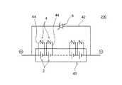
或いは、図3に示す形態の組電池20や図4に示す形態の制御システム(制御装置)200のように、二次電池2の直列接続全体の正極末端の上流側から負極末端の下流側までの間に並列に一つの第1バイパス回路22,42を設ける一方、直列する二次電池2の個々についてバリスタ4を含む第2バイパス回路24,44が形成されている。このような構成によると、何らかの原因で第2電圧V2以上の高電圧が組電池20,40に印加されるような状態(典型的には1秒以下のような瞬間的な過電圧入力状態)が生じた際に、上記直列接続している二次電池群の正極側からセル2毎にバリスタ4を短絡させていくこと(即ちセル2毎に第2バイパス回路24,44に充電電流を迂回させること)ができる。このため、例えば1秒以下のような瞬間的な過電圧入力状態が生じて上記直列接続の正極側の幾つかのバリスタ4が短絡したとしても、組電池20,40の負極側の残りの二次電池2の直列接続を維持し、組電池としての機能を残存させることができる。
この場合、個々の第2バイパス回路に含まれるバリスタのバリスタ電圧は、第2電圧値を第2バイパス回路の数で割って得られる電圧値に設定することができる(換言すれば、全バリスタのバリスタ電圧値の総和が第2電圧値となり得る。)。例えば、直列接続される50個の規定最大充電電圧値4.1Vのリチウムイオン電池のそれぞれに対して一つのバリスタを含む一つの第2バイパス回路が形成される場合であって、第2電圧値を210Vに設定した場合、個々のバリスタのバリスタ電圧を例えば4.2Vに設定することができる。
また、図3や図4に示すような構成によると、組電池20,40中に特異的に劣化してしまったセル2が存在する場合に不安定モードに至る可能性を低減させることができる。具体的には次のとおりである。即ち、通常使用において何らかの原因によって例えば組電池中のセルが一つだけ極端に劣化してしまった場合、特性の変化として一般に抵抗上昇する現象がみられる。かかる抵抗上昇したセルは、通電時の電圧変化が大きくなり、結果、組電池を構成する他のセルと比較して過充電の環境に曝される。しかし、図3や図4に示すような構成によると、所定の電圧(例えば単電池セル当りで4.3V)に達したときにバリスタが印加電圧により崩落し、短絡する。そしてバリスタが短絡すると、上記劣化セルは外部短絡状態に陥るところ、かかる外部短絡状態においては当該セルは不安定モードに移行せずに使用不可能な状態に陥る。このため、上記不安定モードのセル(単電池セル)の使用を回避し、組電池の安全性を向上させることができる。From the viewpoint of simplifying the circuit configuration and facilitating the construction of the assembled battery or the control system, as shown in FIG. 1 and FIG. 2 described above, the upstream side of the positive terminal of the entire series connection of the
Alternatively, from the upstream side of the positive terminal of the entire series connection of the
In this case, the varistor voltage of the varistors included in the individual second bypass circuits can be set to a voltage value obtained by dividing the second voltage value by the number of the second bypass circuits (in other words, the varistor voltage of all the varistors). The sum of the varistor voltage values can be the second voltage value). For example, in the case where one second bypass circuit including one varistor is formed for each of 50 lithium ion batteries having a specified maximum charging voltage value of 4.1 V connected in series, the second voltage value Is set to 210V, the varistor voltage of each varistor can be set to, for example, 4.2V.
Further, according to the configuration as shown in FIG. 3 or FIG. 4, it is possible to reduce the possibility of reaching the unstable mode when the
以下の実施例によって、本発明を更に詳しく説明するが、本発明の構成をかかる実施例として挙げたものに限定することを意図したものではない。 The following examples further illustrate the invention, but are not intended to limit the construction of the invention to those listed as such examples.
<組電池の作製>
組電池に組み込む非水系二次電池としてリチウムイオン電池を作製した。即ち、正極活物質であるLiCoO2と、導電助材であるアセチレンブラック(AB)と、結着材であるポリフッ化ビニリデン(PVDF)を、質量比でLiCoO2/AB/PVDF=85/5/10となるように分散溶媒であるNMP(N−メチル−2−ピロリドン)に添加し、よく混合することによって正極活物質層形成用ペーストを調製した。得られた正極活物質層形成用ペーストを、長さ500mm、幅52mm、厚さ15μmのアルミニウム箔上に塗布し、ロールプレスによる処理を行って、該アルミニウム箔上に正極活物質層を形成して成る正極集電体シートを作製した。<Production of assembled battery>
A lithium ion battery was produced as a non-aqueous secondary battery to be incorporated into the assembled battery. That is, LiCoO2 that is a positive electrode active material, acetylene black (AB) that is a conductive additive, and polyvinylidene fluoride (PVDF) that is a binder, LiCoO2 / AB / PVDF = 85/5 / A positive electrode active material layer forming paste was prepared by adding to NMP (N-methyl-2-pyrrolidone) as a dispersion solvent and mixing well. The obtained paste for forming a positive electrode active material layer is applied onto an aluminum foil having a length of 500 mm, a width of 52 mm, and a thickness of 15 μm, and a roll press treatment is performed to form a positive electrode active material layer on the aluminum foil. A positive electrode current collector sheet was prepared.
一方、負極活物質である天然黒鉛系炭素材料(グラファイト)と、結着材であるスチレン−ブタジエン共重合体(SBR)と、増粘材であるカルボキシメチルセルロース(CMC)を、質量比でグラファイト/SBR/CMC=95/2.5/2.5となるように分散溶媒である水に添加し、よく混合することによって負極活物質層形成用ペーストを調製した。得られた負極活物質層形成用ペーストを、長さ550mm、幅54mm、厚さ10μmの銅箔上に塗布し、ロールプレスによる処理を行って、該銅箔上に負極活物質層を形成して成る負極集電体シートを作製した。なお、正極の理論容量と負極の理論容量との比率が1(正極):1.5(負極)となるように上記ペーストの塗布量を調節した。
こうして得られた正極集電体シート及び負極集電体シートを、長さ600mm、幅60mm、厚さ25μmのポリプロピレン/ポリエチレン複合体多孔質膜であるセパレータシート(2枚)とともに捲回し(20周巻き)、リチウムイオン電池用の円筒形状捲回電極体を作製した。On the other hand, a natural graphite-based carbon material (graphite) that is a negative electrode active material, a styrene-butadiene copolymer (SBR) that is a binder, and carboxymethyl cellulose (CMC) that is a thickener are graphite / A negative electrode active material layer forming paste was prepared by adding to water as a dispersion solvent so that SBR / CMC = 95 / 2.5 / 2.5 and mixing well. The obtained negative electrode active material layer forming paste was applied onto a copper foil having a length of 550 mm, a width of 54 mm, and a thickness of 10 μm, and a roll press treatment was performed to form a negative electrode active material layer on the copper foil. A negative electrode current collector sheet was prepared. The amount of paste applied was adjusted so that the ratio between the theoretical capacity of the positive electrode and the theoretical capacity of the negative electrode was 1 (positive electrode): 1.5 (negative electrode).
The positive electrode current collector sheet and the negative electrode current collector sheet thus obtained were wound together with a separator sheet (two sheets) that is a polypropylene / polyethylene composite porous film having a length of 600 mm, a width of 60 mm, and a thickness of 25 μm (20 laps). Winding), a cylindrical wound electrode body for a lithium ion battery was produced.
作製した捲回電極体に正負極それぞれのリード端子を溶接し、捲回電極体に対応する形状のアルミニウム製の箱形容器(内容積:約16mL)に収容した。容器には適当量の電解液(質量比1:1:1であるエチレンカーボネート、エチルメチルカーボネートおよびジメチルカーボネートの混合溶媒にリチウム塩として濃度1MとなるLiPF6を溶解した非水電解液)を注入し、封止した。これにより、組電池の単電池セルとして使用する捲回型電極体を備える密閉型リチウムイオン電池(二次電池)を作製した。The lead terminals of the positive and negative electrodes were welded to the wound electrode body thus produced and accommodated in an aluminum box-shaped container (internal volume: about 16 mL) having a shape corresponding to the wound electrode body. An appropriate amount of electrolyte (non-aqueous electrolyte in which LiPF6 having a concentration of 1 M as a lithium salt is dissolved in a mixed solvent of ethylene carbonate, ethyl methyl carbonate and dimethyl carbonate having a mass ratio of 1: 1: 1) is injected into the container. And sealed. This produced the sealed lithium ion battery (secondary battery) provided with the wound electrode body used as a single battery cell of the assembled battery.
而して、第1実施例の組電池を次のように構築した。即ち、予め満充電しておいた上記リチウムイオン電池50個を直列に接続し、さらに上述した図1に示すように、当該50個のリチウムイオン電池の直列接続における正極側上流と負極側下流との間にツェナー電圧5.6Vのツェナーダイオードが計42個直列して成る第1バイパス回路を並列に形成した。さらに、バリスタ電圧が235.2Vであるバリスタを含む第2バイパス回路を、当該50個のリチウムイオン電池の直列接続と第1バイパス回路との両方に並列となるように形成した。
また、第2実施例の組電池を次のように構築した。即ち、上記第1実施例の組電池と同様に、リチウムイオン電池50個を直列に接続し、さらに当該直列接続の全体に対して並列にツェナー電圧5.6Vのツェナーダイオードが計42個直列して成る第1バイパス回路を形成した。そして、第2実施例では、上述した図3に示すように、50個のリチウムイオン電池の一つ一つに対してバリスタ電圧が約4.3Vであるバリスタを含む第2バイパス回路を並列にそれぞれ形成した。
また、比較例の組電池として上記第1バイパス回路及び第2バイパス回路のいずれも形成せずに上記リチウムイオン電池50個を直列に接続したのみの組電池を構築した。Thus, the assembled battery of the first example was constructed as follows. That is, 50 lithium ion batteries that have been fully charged in advance are connected in series, and as shown in FIG. 1 described above, the upstream side of the positive electrode and the downstream side of the negative electrode in the serial connection of the 50 lithium ion batteries A first bypass circuit composed of a total of 42 Zener diodes having a Zener voltage of 5.6 V was formed in parallel. Further, a second bypass circuit including a varistor having a varistor voltage of 235.2 V was formed in parallel with both the series connection of the 50 lithium ion batteries and the first bypass circuit.
The assembled battery of the second example was constructed as follows. That is, like the assembled battery of the first embodiment, 50 lithium ion batteries are connected in series, and a total of 42 Zener diodes with a Zener voltage of 5.6 V are connected in series with the entire series connection. A first bypass circuit was formed. And in 2nd Example, as shown in FIG. 3 mentioned above, the 2nd bypass circuit containing the varistor whose varistor voltage is about 4.3V with respect to each of 50 lithium ion batteries is paralleled. Each was formed.
In addition, an assembled battery in which 50 lithium ion batteries were connected in series without forming either the first bypass circuit or the second bypass circuit was constructed as an assembled battery of a comparative example.
上記構築した第1実施例、第2実施例および比較例の組電池を用いて所定の評価用入力回路を構成した。そして、一定期間充放電を繰り返してSOCをほぼ80%状態としたときにバリスタ電圧を上回る高い電圧(具体的には一つの組電池に対して245〜250V)での充電処理を所定時間(約1分間〜10分間)行った。その後、通電を終了し、リチウムイオン電池の状態を調べたところ、比較例の組電池に含まれるリチウムイオン電池では、負極側にリチウムの析出が認められた。一方、第1バイパス回路に加えて第2バイパス回路を含む第1実施例及び第2実施例の組電池に含まれるリチウムイオン電池では、負極側にリチウム析出は認められなかった。 A predetermined evaluation input circuit was configured using the assembled batteries of the first, second, and comparative examples constructed as described above. Then, the charging process at a high voltage (specifically, 245 to 250 V for one assembled battery) exceeding the varistor voltage when charging and discharging are repeated for a certain period to bring the SOC to approximately 80% state is performed for a predetermined time (about 1 minute to 10 minutes). Thereafter, energization was terminated and the state of the lithium ion battery was examined. In the lithium ion battery included in the assembled battery of the comparative example, lithium deposition was observed on the negative electrode side. On the other hand, in the lithium ion batteries included in the assembled batteries of the first example and the second example including the second bypass circuit in addition to the first bypass circuit, no lithium deposition was observed on the negative electrode side.
上記実施例からも明らかなように、上記第1バイパス回路に加えてさらに適切なバリスタ電圧のバリスタを含む第2バイパス回路をフェイルセーフ機能として備えた組電池(又は制御システム)によると、充電時に過電圧が組電池に印加されるような状態が生じた際にも当該組電池に含まれる二次電池を過充電から保護し、過充電によって当該二次電池に不具合(例えばリチウムイオン電池における負極側のリチウム析出)が発生することを未然に防止することができる。
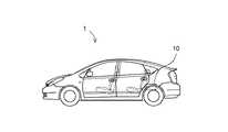
従って、本発明の組電池(或いは組電池を含む制御システム)は、特に自動車等の車両に搭載されるモーター用電源(或いは電源装置)として好適である。従って、図5に示すように、本発明によって上記のように説明した構成の組電池10(或いは制御システム)を備える車両1(典型的には自動車、特にハイブリッド自動車、電気自動車、燃料電池自動車のような電動機を備える自動車)を提供することができる。
以上、本発明を好適な実施形態及び実施例により説明してきたが、こうした記述は限定事項ではなく、勿論、種々の改変が可能である。As is clear from the above embodiment, according to the assembled battery (or control system) provided with the second bypass circuit including a varistor having an appropriate varistor voltage in addition to the first bypass circuit as a fail-safe function, during charging, Even when a situation where an overvoltage is applied to the assembled battery occurs, the secondary battery included in the assembled battery is protected from overcharging, and the secondary battery malfunctions due to overcharging (for example, the negative electrode side in a lithium ion battery) Generation of lithium) can be prevented in advance.
Therefore, the assembled battery (or control system including the assembled battery) of the present invention is particularly suitable as a power source (or power supply device) for a motor mounted on a vehicle such as an automobile. Therefore, as shown in FIG. 5, a vehicle 1 (typically an automobile, particularly a hybrid automobile, an electric automobile, or a fuel cell automobile) provided with the assembled battery 10 (or control system) having the configuration described above according to the present invention. An automobile equipped with such an electric motor can be provided.
As mentioned above, although this invention was demonstrated by suitable embodiment and an Example, such description is not a limitation matter and of course, various modifications are possible.
1 車両
2 二次電池
4 バリスタ
6 ツェナーダイオード
10,20,30,40 組電池
12,22,32,42 第1バイパス回路
14,24,34,44 第2バイパス回路
100,200 制御システム(制御装置)DESCRIPTION OF
Claims (5)
Translated fromJapanese前記複数の二次電池の直列接続に対して充電時に逆方向接続となる向きで並列に接続されたツェナーダイオードを含む第1バイパス回路と、
前記二次電池および前記ツェナーダイオードに対して並列に接続されたバリスタを含む第2バイパス回路と、
を備えており、
ここで前記第1バイパス回路は、前記複数の二次電池からなる直列接続の全体に対して並列に一つ形成されており、前記ツェナーダイオードのツェナー電圧は、当該組電池の規定最大充電電圧値よりも高い所定の電圧値に設定されている第1電圧値が組電池に印可されたときに前記第1バイパス回路が通電されるように決定されており、且つ、
前記第2バイパス回路は、前記複数の二次電池の各々に対して並列に複数形成されており、前記バリスタのバリスタ電圧は、前記第1電圧値と等しいか又はそれよりも高い所定の電圧値に設定されている第2電圧値が組電池に印可されたときに前記第2バイパス回路が通電されるように決定されていることを特徴とする、組電池。A battery pack comprising a plurality of secondary batteries connected in series,
A first bypass circuit including a Zener diode connected in parallel in a direction that is a reverse connection during charging with respect to a series connection of the plurality of secondary batteries;
A second bypass circuit including a varistor connected in parallel to the secondary battery and the Zener diode;
With
Here,the first bypass circuit is formed in parallel with the entire series connection composed of the plurality of secondary batteries, and the Zener voltage of the Zener diode is a specified maximum charging voltage value of the assembled battery. The first bypass circuit is determined to be energized when a first voltage value set to a higher predetermined voltage value is applied to the assembled battery, and
A plurality of the second bypass circuits are formed in parallel to each of the plurality of secondary batteries, and a varistor voltage of the varistor is a predetermined voltage value equal to or higher than the first voltage value. An assembled battery, wherein the second bypass circuit is determined to be energized when a second voltage value set to 1 is applied to the assembled battery.
前記組電池における前記複数の二次電池の直列接続に対して充電時に逆方向接続となる向きで並列に接続されたツェナーダイオードを含む第1バイパス回路と、A first bypass circuit including a Zener diode connected in parallel in a direction to be connected in the reverse direction during charging with respect to the series connection of the plurality of secondary batteries in the assembled battery;
前記二次電池および前記ツェナーダイオードに対して並列に接続されたバリスタを含む第2バイパス回路と、A second bypass circuit including a varistor connected in parallel to the secondary battery and the Zener diode;
が形成されており、Is formed,
ここで前記第1バイパス回路は、前記複数の二次電池からなる直列接続の全体に対して並列に一つ形成されており、前記第1バイパス回路に含まれるツェナーダイオードのツェナー電圧は、前記組電池の規定最大充電電圧値よりも高い所定の電圧値に設定されている第1電圧値が該組電池に印可されたときに前記第1バイパス回路が通電されるように決定されており、且つ、Here, one first bypass circuit is formed in parallel with respect to the entire series connection composed of the plurality of secondary batteries, and a Zener voltage of a Zener diode included in the first bypass circuit is the set. The first bypass circuit is determined to be energized when a first voltage value set to a predetermined voltage value higher than a specified maximum charging voltage value of the battery is applied to the assembled battery; and ,
前記第2バイパス回路は、前記複数の二次電池の各々に対して並列に複数形成されており、前記バリスタのバリスタ電圧は、前記第1電圧値と等しいか又はそれよりも高い所定の電圧値に設定されている第2電圧値が前記組電池に印可されたときに前記第2バイパス回路が通電されるように決定されていることを特徴とする、組電池の制御システム。A plurality of the second bypass circuits are formed in parallel to each of the plurality of secondary batteries, and a varistor voltage of the varistor is a predetermined voltage value equal to or higher than the first voltage value. An assembled battery control system, wherein the second bypass circuit is determined to be energized when a second voltage value set to 1 is applied to the assembled battery.
Priority Applications (4)
| Application Number | Priority Date | Filing Date | Title |
|---|---|---|---|
| JP2008219452AJP4771180B2 (en) | 2008-08-28 | 2008-08-28 | Battery pack and battery pack control system |
| US13/060,714US9196932B2 (en) | 2008-08-28 | 2009-08-06 | Assembled battery and assembled battery control system |
| PCT/JP2009/063937WO2010024100A1 (en) | 2008-08-28 | 2009-08-06 | Assembled battery, and control system for the assembled battery |
| CN200980133424.2ACN102138265B (en) | 2008-08-28 | 2009-08-06 | Control systems for batteries and battery packs |
Applications Claiming Priority (1)
| Application Number | Priority Date | Filing Date | Title |
|---|---|---|---|
| JP2008219452AJP4771180B2 (en) | 2008-08-28 | 2008-08-28 | Battery pack and battery pack control system |
Publications (2)
| Publication Number | Publication Date |
|---|---|
| JP2010057265A JP2010057265A (en) | 2010-03-11 |
| JP4771180B2true JP4771180B2 (en) | 2011-09-14 |
Family
ID=41721272
Family Applications (1)
| Application Number | Title | Priority Date | Filing Date |
|---|---|---|---|
| JP2008219452AActiveJP4771180B2 (en) | 2008-08-28 | 2008-08-28 | Battery pack and battery pack control system |
Country Status (4)
| Country | Link |
|---|---|
| US (1) | US9196932B2 (en) |
| JP (1) | JP4771180B2 (en) |
| CN (1) | CN102138265B (en) |
| WO (1) | WO2010024100A1 (en) |
Families Citing this family (13)
| Publication number | Priority date | Publication date | Assignee | Title |
|---|---|---|---|---|
| DE102010038882A1 (en)* | 2010-08-04 | 2012-02-09 | Sb Limotive Company Ltd. | Battery system and method for charging a plurality of series-connected battery cells |
| US20140159664A1 (en)* | 2011-07-08 | 2014-06-12 | Nec Energy Devices, Ltd. | Method of manufacturing battery pack and battery pack |
| US9385398B2 (en)* | 2011-09-08 | 2016-07-05 | Toyota Jidosha Kabushiki Kaisha | Method for manufacturing lithium secondary battery |
| US8630077B2 (en)* | 2011-12-22 | 2014-01-14 | Sunpower Corporation | Circuits and methods for limiting open circuit voltage of photovoltaic strings |
| JP5884683B2 (en)* | 2012-08-30 | 2016-03-15 | 株式会社デンソー | Battery monitoring device |
| CN102882251B (en)* | 2012-09-25 | 2014-09-03 | 上海空间电源研究所 | Charging feedback control system and method for lithium ion storage batteries |
| CN103762332A (en)* | 2014-01-28 | 2014-04-30 | 天津先众科技有限公司 | Cylindrical lithium ion battery pack and combination method thereof |
| CN103812198B (en)* | 2014-03-05 | 2015-09-02 | 宁波市安博新能源科技有限公司 | A kind of battery charges anti-circnit NOT |
| DE102014209476A1 (en) | 2014-05-20 | 2015-11-26 | Robert Bosch Gmbh | Method for operating a battery system |
| DE102015203269A1 (en)* | 2015-02-24 | 2016-08-25 | Siemens Aktiengesellschaft | Storage system for storing electrical energy |
| JP6774628B2 (en) | 2016-12-07 | 2020-10-28 | 株式会社オートネットワーク技術研究所 | Battery monitoring device protection circuit and battery monitoring device |
| US11817596B2 (en)* | 2021-02-04 | 2023-11-14 | GM Global Technology Operations LLC | Rechargeable energy storage system with backup network |
| BG113805A (en)* | 2023-11-02 | 2025-05-15 | "Инноватроник" Еоод | High voltage battery module |
Family Cites Families (20)
| Publication number | Priority date | Publication date | Assignee | Title |
|---|---|---|---|---|
| JPS57193934A (en)* | 1981-05-25 | 1982-11-29 | Nippon Telegraph & Telephone | Lightning surge protecting circuit |
| US4439721A (en)* | 1982-02-12 | 1984-03-27 | Outboard Marine Corporation | Magneto alternator regulator with tachometer output |
| DE3318588A1 (en)* | 1983-05-21 | 1984-11-22 | Brown, Boveri & Cie Ag, 6800 Mannheim | VARISTOR LOCKING ELEMENT |
| US4719401A (en)* | 1985-12-04 | 1988-01-12 | Powerplex Technologies, Inc. | Zener diode looping element for protecting a battery cell |
| JPS6324850A (en)* | 1986-07-18 | 1988-02-02 | Sofuto Shirika Kk | Quality improving and preserving agent for manufacturing green tea |
| JPH0547478Y2 (en)* | 1986-07-30 | 1993-12-14 | ||
| JPS6381635A (en)* | 1986-09-26 | 1988-04-12 | Hitachi Ltd | optical head |
| JPH0343817Y2 (en)* | 1986-11-15 | 1991-09-13 | ||
| US5821733A (en)* | 1994-02-22 | 1998-10-13 | Packard Bell Nec | Multiple cell and serially connected rechargeable batteries and charging system |
| JP3716618B2 (en)* | 1998-05-14 | 2005-11-16 | 日産自動車株式会社 | Battery control device |
| JP2001136666A (en)* | 1999-11-09 | 2001-05-18 | Toyota Motor Corp | Battery control device |
| JP2002186192A (en)* | 2000-12-18 | 2002-06-28 | Mitsubishi Electric Corp | Battery charger |
| JP2002238179A (en) | 2001-02-13 | 2002-08-23 | Hitachi Ltd | Rechargeable battery charger and charging method |
| US6798170B2 (en)* | 2002-02-08 | 2004-09-28 | Valence Technology, Inc. | Electrical power source apparatuses, circuits, electrochemical device charging methods, and methods of charging a plurality of electrochemical devices |
| JP4095849B2 (en)* | 2002-07-10 | 2008-06-04 | 日本特殊陶業株式会社 | Heater control device and gas detection device |
| JP2004087238A (en)* | 2002-08-26 | 2004-03-18 | Nissan Motor Co Ltd | Stacked battery |
| JP4353050B2 (en)* | 2004-09-30 | 2009-10-28 | ソニー株式会社 | battery pack |
| JP4116609B2 (en)* | 2004-11-04 | 2008-07-09 | パナソニックEvエナジー株式会社 | Power supply control device, electric vehicle and battery control unit |
| JP4275078B2 (en)* | 2005-01-13 | 2009-06-10 | 三洋電機株式会社 | Battery current limit control method |
| US7880434B2 (en)* | 2008-05-21 | 2011-02-01 | Southwest Electronic Energy Corporation | System for balancing a plurality of battery pack system modules connected in series |
- 2008
- 2008-08-28JPJP2008219452Apatent/JP4771180B2/enactiveActive
- 2009
- 2009-08-06USUS13/060,714patent/US9196932B2/enactiveActive
- 2009-08-06WOPCT/JP2009/063937patent/WO2010024100A1/ennot_activeCeased
- 2009-08-06CNCN200980133424.2Apatent/CN102138265B/enactiveActive
Also Published As
| Publication number | Publication date |
|---|---|
| US20110175573A1 (en) | 2011-07-21 |
| WO2010024100A1 (en) | 2010-03-04 |
| CN102138265A (en) | 2011-07-27 |
| JP2010057265A (en) | 2010-03-11 |
| CN102138265B (en) | 2014-03-19 |
| US9196932B2 (en) | 2015-11-24 |
Similar Documents
| Publication | Publication Date | Title |
|---|---|---|
| JP4771180B2 (en) | Battery pack and battery pack control system | |
| US8859124B2 (en) | Integrated circuit and battery pack using the same | |
| US9893377B2 (en) | Nonaqueous electrolyte battery, battery pack and vehicle | |
| KR100903244B1 (en) | Assembled battery system, method for charging assembled battery, and charging cleaner | |
| JP4314223B2 (en) | Regenerative power storage system, storage battery system and automobile | |
| US11251414B2 (en) | Electrode group, secondary battery, battery pack, and vehicle | |
| JP2008277106A (en) | Nonaqueous electrolyte battery and battery system | |
| CN114665169B (en) | Method for restoring activity of lithium-ion battery and lithium-ion battery | |
| KR20170107894A (en) | Laminated body, secondary battery, battery pack and vehicle | |
| CN101150209A (en) | Power Systems and Electric Vehicles | |
| CN103782441B (en) | The manufacture method of lithium secondary battery | |
| US6773849B2 (en) | Battery set and method for producing electric power output | |
| JP2011086530A (en) | Battery pack, and power supply device | |
| JP6776291B2 (en) | Batteries, battery packs, vehicles, and stationary power supplies | |
| CN101485034A (en) | Lithium rechargeable battery | |
| EP1363347A1 (en) | Battery and related method | |
| CN110277553A (en) | Electrode, secondary battery, battery pack and vehicle | |
| CN110366793B (en) | Nonaqueous electrolyte battery, battery pack, and battery system | |
| JP2009259607A (en) | Battery pack | |
| JP7628503B2 (en) | High power, extended temperature range, and overcharge-resistant rechargeable battery cells and battery packs | |
| JP2016062810A (en) | Non-aqueous electrolyte secondary battery negative electrode and non-aqueous electrolyte secondary battery equipped with the same | |
| JP2005267886A (en) | Secondary battery | |
| JP2009230900A (en) | Non-aqueous electrolyte secondary battery pack | |
| JP2013037863A (en) | Battery pack | |
| JP2013045658A (en) | Capacity recovery method of lithium secondary battery |
Legal Events
| Date | Code | Title | Description |
|---|---|---|---|
| A131 | Notification of reasons for refusal | Free format text:JAPANESE INTERMEDIATE CODE: A131 Effective date:20100805 | |
| A521 | Written amendment | Free format text:JAPANESE INTERMEDIATE CODE: A523 Effective date:20100930 | |
| TRDD | Decision of grant or rejection written | ||
| A01 | Written decision to grant a patent or to grant a registration (utility model) | Free format text:JAPANESE INTERMEDIATE CODE: A01 Effective date:20110526 | |
| A01 | Written decision to grant a patent or to grant a registration (utility model) | Free format text:JAPANESE INTERMEDIATE CODE: A01 | |
| A61 | First payment of annual fees (during grant procedure) | Free format text:JAPANESE INTERMEDIATE CODE: A61 Effective date:20110608 | |
| FPAY | Renewal fee payment (event date is renewal date of database) | Free format text:PAYMENT UNTIL: 20140701 Year of fee payment:3 | |
| R151 | Written notification of patent or utility model registration | Ref document number:4771180 Country of ref document:JP Free format text:JAPANESE INTERMEDIATE CODE: R151 | |
| FPAY | Renewal fee payment (event date is renewal date of database) | Free format text:PAYMENT UNTIL: 20140701 Year of fee payment:3 |