JP4770856B2 - Transfer robot - Google Patents
Transfer robotDownload PDFInfo
- Publication number
- JP4770856B2 JP4770856B2JP2008073833AJP2008073833AJP4770856B2JP 4770856 B2JP4770856 B2JP 4770856B2JP 2008073833 AJP2008073833 AJP 2008073833AJP 2008073833 AJP2008073833 AJP 2008073833AJP 4770856 B2JP4770856 B2JP 4770856B2
- Authority
- JP
- Japan
- Prior art keywords
- clamp
- link
- arm
- actuator
- attached
- Prior art date
- Legal status (The legal status is an assumption and is not a legal conclusion. Google has not performed a legal analysis and makes no representation as to the accuracy of the status listed.)
- Expired - Fee Related
Links
Images


Classifications
- B—PERFORMING OPERATIONS; TRANSPORTING
- B25—HAND TOOLS; PORTABLE POWER-DRIVEN TOOLS; MANIPULATORS
- B25J—MANIPULATORS; CHAMBERS PROVIDED WITH MANIPULATION DEVICES
- B25J9/00—Programme-controlled manipulators
- B25J9/06—Programme-controlled manipulators characterised by multi-articulated arms
- B—PERFORMING OPERATIONS; TRANSPORTING
- B25—HAND TOOLS; PORTABLE POWER-DRIVEN TOOLS; MANIPULATORS
- B25J—MANIPULATORS; CHAMBERS PROVIDED WITH MANIPULATION DEVICES
- B25J15/00—Gripping heads and other end effectors
- B25J15/02—Gripping heads and other end effectors servo-actuated
- B25J15/0206—Gripping heads and other end effectors servo-actuated comprising articulated grippers
- B25J15/022—Gripping heads and other end effectors servo-actuated comprising articulated grippers actuated by articulated links
- B—PERFORMING OPERATIONS; TRANSPORTING
- B25—HAND TOOLS; PORTABLE POWER-DRIVEN TOOLS; MANIPULATORS
- B25J—MANIPULATORS; CHAMBERS PROVIDED WITH MANIPULATION DEVICES
- B25J5/00—Manipulators mounted on wheels or on carriages
- B25J5/007—Manipulators mounted on wheels or on carriages mounted on wheels
- Y—GENERAL TAGGING OF NEW TECHNOLOGICAL DEVELOPMENTS; GENERAL TAGGING OF CROSS-SECTIONAL TECHNOLOGIES SPANNING OVER SEVERAL SECTIONS OF THE IPC; TECHNICAL SUBJECTS COVERED BY FORMER USPC CROSS-REFERENCE ART COLLECTIONS [XRACs] AND DIGESTS
- Y10—TECHNICAL SUBJECTS COVERED BY FORMER USPC
- Y10T—TECHNICAL SUBJECTS COVERED BY FORMER US CLASSIFICATION
- Y10T74/00—Machine element or mechanism
- Y10T74/20—Control lever and linkage systems
- Y10T74/20207—Multiple controlling elements for single controlled element
- Y10T74/20305—Robotic arm
Landscapes
- Engineering & Computer Science (AREA)
- Robotics (AREA)
- Mechanical Engineering (AREA)
- Manipulator (AREA)
Description
Translated fromJapanese本発明は、台車等の搬送対象物を移送するためのクランプ装置及び移送用ロボットに関する。 The present invention relates to a clamp device and a transfer robot for transferring a conveyance object such as a carriage.
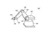
図9及び図10は、従来の移送用ロボットを示す図でり、それぞれ垂直多関節型及び水平多関節型のロボットを示す。垂直多関節型ロボット200は、床面に接地される土台201と、土台201にリンク機構(図示せず)を介して取り付けられた支持部202と、支持部202にリンク機構203により垂直方向に回転可動に取り付けられた第1アーム204と、第1アーム204にリンク機構205により垂直方向に回転可動に取り付けられた第2アームと、第2アームにリンク機構207により垂直方向に回転可動に取り付けられた保持部208と、保持部208に取り付けられたピン209とを有する。リンク機構203、205、207が回転することで、第1アーム204、第2アーム206及び保持部208が垂直方向に移動する。また、土台201と支持部202との間に設けられたリンク機構により、支持部202が水平方向に回転する。 FIG. 9 and FIG. 10 are diagrams showing a conventional transfer robot, which respectively show a vertical articulated type and a horizontal articulated type robot. The vertical articulated
また、水平多関節型ロボット300は、床面に接地される土台301と、土台301に取り付けられたリンク機構302と、リンク機構302により水平方向に回転可動に取り付けられた第1アーム303と、第1アーム303にリンク機構305により水平方向に回転可動に取り付けられた第2アーム306と、第2アーム306に接続する、電気線を含むホース304と、第2アーム306に設けられ垂直方向に上下するシリンダ307とを有する。リンク機構302、305が回転することで、第1アーム303、第2アーム306が水平方向に移動する。このような水平方向に搬送対象物を搬送する搬送ロボットとしては特許文献1に記載の移送用ロボットが公知である。 The horizontal articulated
ところで、このような移送用ロボットにおいて、従来、重量物を搬送する際のクランプ機構として以下の方式が考えられる。
1)台車に設けられたクランプ穴にハンドピンを挿し固定する方式
2)台車に設けられたクランプ部(バー等)をハンドで挟み込み固定する方式
1) A method of inserting and fixing a hand pin in a clamp hole provided in the carriage 2) A method of clamping and fixing a clamp portion (bar, etc.) provided in the carriage with a hand
しかしながら、台車の重さなどのバラツキが大きい状況で上記の方式を採用すると以下の問題が生じる。1)の場合には、ハンドのピンを直動で台車等のクランプ穴に挿す。しかし、ピン先端はテーパーになっているため、台車等のクランプ穴の誘い込みを増やす必要がある。又は、停止精度を上げるため、更なる外部の位置決め機構が必要となる。また、クランプ穴の誘い込みテーパーを増やすことで停止位置などの誤差を吸収できるが、ピンも穴部も大きくなり、スペースに制約がある場合には成立が困難である。 However, when the above method is employed in a situation where the weight of the carriage is very varied, the following problems occur. In the case of 1), insert the pin of the hand directly into the clamp hole of the carriage. However, since the tip of the pin is tapered, it is necessary to increase the incentive of a clamp hole such as a carriage. Alternatively, a further external positioning mechanism is required to increase the stopping accuracy. In addition, an error such as a stop position can be absorbed by increasing the guide taper of the clamp hole, but it is difficult to establish when the pin and the hole are large and space is limited.
2)の場合は、クランプハンドのストロークが大きくなるため、安全性を考慮する場合には、低推力化するか、又はカバーを取り付け中ればならない。しかしながら、低推力では重量物を固定できない。また、カバーを取り付けるとハンド部が大きくなりスペースに制限がある場合には成立が困難である。 In the case of 2), since the stroke of the clamp hand becomes large, when considering safety, the thrust must be reduced or the cover must be attached. However, a heavy object cannot be fixed with low thrust. In addition, when the cover is attached, the hand portion becomes large and it is difficult to establish it when space is limited.
台車等は作業者と共存しているため、作業者又は位置決めのないコンベアに乗って運ばれるため、クランプ位置での停止位置精度が低い。また、更にコンベアなどの位置決め機構を追加すると人と共存するための安全対策も必要となり非常にコストが高くなる。よって、位置精度が低い状態でクランプを行わないといけない。 Since the carriage or the like coexists with the worker, the carriage is carried on a worker or a conveyor having no positioning, so the stop position accuracy at the clamp position is low. Further, if a positioning mechanism such as a conveyor is further added, a safety measure for coexisting with a person is required, and the cost becomes very high. Therefore, clamping must be performed in a state where the positional accuracy is low.
本発明は、このような問題点を解決するためになされたものであり、バラツキが大きくてもクランプすることができるクランプ装置、および台車を提供することを目的とする。 The present invention has been made to solve such problems, and an object of the present invention is to provide a clamping device and a carriage that can be clamped even if there is large variation.
上述した目的を達成するために、本発明に係るクランプ装置は、直動するアクチュエータと、前記アクチュエータの直動方向と直交する方向に伸びるリンクと、リンクの両端に回転可動に取り付けられ、被クランプ部をクランプするツメ部を有するクランプ部とを有し、前記アクチュエータが直動すると共に前記クランプ部が回転して前記被クランプ部をクランプするものである。 In order to achieve the above-described object, a clamping device according to the present invention includes a linearly acting actuator, a link extending in a direction perpendicular to the linearly moving direction of the actuator, and rotatably attached to both ends of the link. And a clamp part having a claw part for clamping the part, and the actuator moves directly and the clamp part rotates to clamp the clamped part.
本発明においては、アクチュエータが直動してクランプ部が内側から被クランプ部をクランプすることにより、台車等と連結することができる。クランプ部の回転機構により、省スペースでクランプ前の台車位置バラツキや移送側装置のハンド部位置バラツキを大幅に吸収することができる。 In the present invention, the actuator can be directly moved and the clamp portion can clamp the clamped portion from the inside, so that it can be connected to a carriage or the like. With the rotation mechanism of the clamp part, it is possible to greatly absorb the truck position fluctuation before clamping and the hand part position fluctuation of the transfer side device in a small space.
本発明に係る移送用ロボットは、土台と、前記土台に設けられたリンク機構と、前記土台に、前記リンク機構により水平方向に回転可動に取り付けられる第1アームと、前記第1アームを前記リンク機構を軸として移動する、当該第1アームの下面に取り付けられたキャスタと、搬送対象物を保持するために前記第1アームの上面に設けられた保持部と、前記保持部の端部に設けられたクランプ装置とを備え、前記リンク機構は、モータと、当該モータによる回転を制御する第1減速機構と、当該第1減速機構に接続し前記第1アームの回動を制御する第2減速機構とを有し、前記クランプ装置は、直動するアクチュエータと、前記アクチュエータの直動方向と直交する方向に伸びるリンクと、リンクの両端に回転可動に取り付けられ、被クランプ部をクランプするツメ部を有するクランプ部と、を有し、前記アクチュエータが直動すると共に前記クランプ部が回転して前記被クランプ部をクランプするものである。 The transfer robot according to the present invention includes a base, a link mechanism provided on the base, a first arm attached to the base so as to be rotatable in a horizontal direction by the link mechanism, and the first arm linked to the base. A caster attached to the lower surface of the first arm that moves about the mechanism, a holding portion provided on the upper surface of the first arm for holding the object to be conveyed, and provided at an end of the holding portion The link mechanism includes a motor, a first speed reduction mechanism that controls rotation by the motor, and a second speed reduction that is connected to the first speed reduction mechanism and controls the rotation of the first arm. The clamp device includes a linearly moving actuator, a link extending in a direction perpendicular to the linearly moving direction of the actuator, and rotatably attached to both ends of the link. Has a clamp portion having a claw portion for clamping the pump unit, wherein the actuator is intended for clamping the clamped portion the clamp portion rotates while linear motion.
本発明においては、さらに、第1アームの下面にキャスタを取り付けロボットの自重を支えるとともに、リンク機構によりアームを水平方向に回動させることで搬送対象物を搬送するようにしたので、低出力のモータを使用することができる。 In the present invention, a caster is attached to the lower surface of the first arm to support the robot's own weight, and the arm is moved in the horizontal direction by the link mechanism to convey the object to be conveyed. A motor can be used.
本発明によれば、バラツキが大きくてもクランプすることができるクランプ装置、および台車を提供することができる。 According to the present invention, it is possible to provide a clamping device and a carriage that can be clamped even if the variation is large.
以下、本発明を適用した具体的な実施の形態について、図面を参照しながら詳細に説明する。この実施の形態は、本発明を、台車等の搬送対象物を移送するためのクランプ装置及び移送用ロボットに適用したものである。 Hereinafter, specific embodiments to which the present invention is applied will be described in detail with reference to the drawings. In this embodiment, the present invention is applied to a clamping device and a transfer robot for transferring a conveyance object such as a carriage.
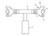
図1及び図2は、本実施の形態にかかるクランプ装置を示す図である。このクランプ装置10は、後述する移送用ロボットの端部に設けられ、台車と結合するために用いられる。クランプ装置10は、直動するアクチュエータ1と、アクチュエータ1の直動方向と直交する方向に伸びるリンク2と、リンク2の両端に回転可動に取り付けられ、被クランプ部8をクランプするクランプヅメ3aを有するクランプ部3と、カバー4とを有する。アクチュエータ1が直動すると共にクランプ部3が回転して被クランプ部8をクランプする。 FIG.1 and FIG.2 is a figure which shows the clamp apparatus concerning this Embodiment. The
このクランプ装置は、例えば台車等に2本のクランプバー(被クランプ部)を設けておき、この2本のクランプバーを、クランプ部3が内側から抱え込んで把持する。クランプ前の台車位置バラツキや移動装置側のハンド位置のバラツキを大幅に吸収することができ、容易にクランプバーを把持することができる。 In this clamp device, for example, two clamp bars (clamped parts) are provided on a carriage or the like, and the two clamp bars are held by the clamp part 3 from the inside and held. Variations in the cart position before clamping and in the hand position on the moving device side can be greatly absorbed, and the clamp bar can be easily gripped.
また、本実施の形態におけるアクチュエータ1は、低出力(例えば80W以下)とすることができる。このアクチュエータ1は、カバー4に固定されている。そして、アクチュエータ1の先端にはリンク2が設けられている。また、クランプ部3において、クランプヅメ3aは、支点6を中心に回転可動にカバー4に取り付けられている。クランプヅメ3aは、リンク2に固定されたピン7と長孔を介して接続されている。このリンク2とクランプ部3の接続点となる長孔部分が力点となり、被クランプ部8とクランプ部3の接点が作用点となっている。 Moreover, the actuator 1 in this Embodiment can be made into low output (for example, 80 W or less). The actuator 1 is fixed to the cover 4. A
本実施の形態においては、クランプヅメ3aを回転させ、リンク2に横方向の力を逃がすことにより、アクチュエータ1にかかる負荷を低減し、低推力化することができる。台車車輪と床面との摩擦や、加速時の慣性力等、搬送中はクランプを外そうとする様々な力が働く。そのため、クランプ部のアクチュエータ1には、それらの力に対応する力が必要となる。 In the present embodiment, the load applied to the actuator 1 can be reduced and the thrust can be reduced by rotating the
ここで、本実施の形態にかかるクランプ装置10は、回転動作の機構を用いて、直動端(7)を回転動作の力点とし、クランプ部3が支点6を中心に回転可動に設けられているため、アクチュエータ1の低推力化を図ることができる。 Here, the
また、直動で直接クランプする機構(ピン又はハンド)を使用すると、スペース制約が生じる。テーパーのあるクランプヅメの一方を回転中心とし、直動アクチュエータでクランプヅメを回転動作でクランプする方式で大きな位置バラツキがある台車等もハンドに位置決めさせながらクランプすることが可能となる。 In addition, when a mechanism (pin or hand) that directly clamps by direct motion is used, space constraints are generated. It is possible to clamp a cart or the like having a large position variation by positioning the clamp grip with a rotation by using a linear motion actuator with one of the clamp clamps having a taper as a rotation center.
図2及び図3は、クランプ装置の動作の様子を示す図であって、それぞれクランプ前、クランプ後を示す図である。図2の状態から、図3に示すように、アクチュエータ1が直動し、クランプ部3が支点6を基準に回転することで、被クランプ部8をクランプすることができる。 2 and 3 are views showing the operation of the clamping device, and are views showing before and after clamping, respectively. From the state of FIG. 2, as shown in FIG. 3, the clamped portion 8 can be clamped by the actuator 1 moving linearly and the clamp portion 3 rotating around the
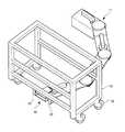
図4乃至図8は、上述のクランプ装置が取り付けられた移送用ロボットを示す図である。移送用ロボット100は、ベース部11、リンク部12a、12b、先端リンク部13及びクランプ装置10を有する。ベース部11を床面に固定し、先端リンク部13に設けられたクランプ装置10により台車31を保持する。そして、リンク部12a、12b及び先端リンク部13がそれぞれ水平方向に回転することで台車31を水平方向に移送することができる。 4 to 8 are views showing a transfer robot to which the above-described clamping device is attached. The
ベース部11は、モータ15aと、モータ15aにより垂直方向を軸として回転する、モータ15aの先端に取り付けられた第1減速機構16aと、第1減速機構16aが取り付けられる土台17とを有する。本実施の形態における移送用ロボット100は2次元的な動きのみを行なうように構成することで、モータ15aの負荷を軽減することができ、例えば80W以下の低出力のものを用いることができる。 The
リンク部12aは、図5に示すように、ベース部11の第1減速機構16aと接続される第2減速機構18bと、第2減速機構18bがその上面片端に取り付けられる第2アームとしてのアーム19bと、モータ15bと、モータ15bによって回転される、アーム19bのもう一方の端部に設けられた第1減速機構16bと、アーム19bを支え移動する、アーム19bの下面に取り付けられたキャスタ20bとを有する。第1減速機構及び第2減速機構は、減速機、ギアボックス、及び歯車等を組み合せ、モータの回転を減速させる機構である。第2減速機構18bも第1減速機構16aと同じく垂直方向を軸として水平方向で回転する。モータ15a、第1減速機構16a、及び第2減速機構18bによりリンク機構が構成される。 As shown in FIG. 5, the
上記ベース部11の第1減速機構16aがモータ15aにより回転され、これにより、第1減速機構16aと接続している第2減速機構18bが回転する。なお、第1減速機構16aと第2減速機構18bとは互いの歯車が嵌合するよう構成される。第2減速機構18bが回転することでアーム19bが水平方向に回動する。リンク部12bもリンク部12aと同様に構成される。 The
先端リンク部13は、第2減速機構18dと、第2減速機構18dがその上面片端に取り付けられる第1アームとしてのアーム19dと、モータ15dと、モータ15dにより回転する第1減速機構16dと、アーム19dの下面に取り付けられアーム19dを支持・移動するキャスタ20dとを有する。この先端リンク部13は、第1減速機構16dに接続するクランプ装置10を有している。 The
そして、図7及び図8に示すように、台車31に取り付けられたクランプバー33をクランプ装置10のクランプ部3が内側から外側に開くように回転してクランプすることで、台車31とクランプ装置10とが連結される。車輪32を有する台車31は、クランプバー33を設けるのみで、クランプ装置10が簡単に連結することができる。 7 and 8, the
本実施の形態においては、省スペースでクランプを行うことができるため、台車等の被クランプ部に、丸棒を配置することで、台車形状、搬送物形状によらず、同機構で人と共存可能な移送用ロボットを実現することができる。 In this embodiment, it is possible to clamp in a space-saving manner, so by arranging a round bar on the clamped part such as a carriage, it is possible to coexist with people in the same mechanism regardless of the shape of the carriage or the shape of the conveyed product. A possible transfer robot can be realized.
なお、本発明は上述した実施の形態のみに限定されるものではなく、本発明の要旨を逸脱しない範囲において種々の変更が可能であることは勿論である。 It should be noted that the present invention is not limited to the above-described embodiments, and various modifications can be made without departing from the scope of the present invention.
1 アクチュエータ
2 リンク
3 クランプ部
3a クランプヅメ
4 カバー
6 支点
7 ピン
8 被クランプ部
10 クランプ装置
11 ベース部
12a、12b リンク部
13 先端リンク部
15a、15b、15c、15d モータ
16a、16b、16c、16d 減速機構
17 土台
18b、18c、18d、18e 減速機構
19b、19c、19d アーム
20b、20c、20d キャスタ
31 台車
32 キャスタ
33 クランプバー
100 移送用ロボットDESCRIPTION OF SYMBOLS 1
Claims (2)
Translated fromJapanese前記土台に設けられたリンク機構と、
前記土台に、前記リンク機構により水平方向に回転可動に取り付けられる第1アームと、
前記第1アームを前記リンク機構を軸として移動する、当該第1アームの下面に取り付けられたキャスタと、
搬送対象物を保持するために前記第1アームの上面に設けられた保持部と、
前記保持部の端部に設けられたクランプ装置とを備え、
前記リンク機構は、
モータと、
当該モータによる回転を制御する第1減速機構と、
当該第1減速機構に接続し前記第1アームの回動を制御する第2減速機構とを有し、
前記クランプ装置は、
直動するアクチュエータと、
前記アクチュエータの直動方向と直交する方向に伸びるリンクと、
リンクの両端に回転可動に取り付けられ、被クランプ部をクランプするツメ部を有するクランプ部と、を有し、
前記リンクは、固定されたピンを有し、
前記ツメ部は、前記ピンと接続する長孔と、テーパーのある二つのクランプヅメと、を有し、
前記アクチュエータが直動すると共に前記クランプ部が回転して前記被クランプ部を内側からクランプし、前記被クランプ部をクランプすると前記リンクと前記被クランプ部とが直線上に配置される移送用ロボット。The foundation,
A link mechanism provided on the base;
A first arm attached to the base so as to be rotatable in the horizontal direction by the link mechanism;
A caster attached to the lower surface of the first arm that moves the first arm about the link mechanism;
A holding portion provided on the upper surface of the first arm for holding a conveyance object;
A clamp device provided at an end of the holding part,
The link mechanism is
A motor,
A first reduction mechanism that controls rotation by the motor;
A second reduction mechanism connected to the first reduction mechanism and controlling the rotation of the first arm;
The clamping device is
A linear actuator,
A link extending in a direction orthogonal to the linear motion direction of the actuator;
A clamp portion that is rotatably attached to both ends of the link and has a claw portion that clamps the clamped portion;
The link has a fixed pin;
The claw portion has a long hole connected to the pin and two clamp claws having a taper,
Transfer robot said actuator clamps the clamp portion rotates the clamped portion from the inside as well as linear motion, the to clamp the clamped portion and the link betweenthe clamped portion is arrangedon a straight line.
Priority Applications (6)
| Application Number | Priority Date | Filing Date | Title |
|---|---|---|---|
| JP2008073833AJP4770856B2 (en) | 2008-03-21 | 2008-03-21 | Transfer robot |
| EP09722695.5AEP2263838B1 (en) | 2008-03-21 | 2009-03-18 | Clamp device and transfer robot |
| US12/922,999US20110036197A1 (en) | 2008-03-21 | 2009-03-18 | Clamping device and transfer robot |
| CN2009801103055ACN101977736B (en) | 2008-03-21 | 2009-03-18 | Clamping device and transfer robot |
| PCT/JP2009/055291WO2009116574A1 (en) | 2008-03-21 | 2009-03-18 | Clamp device and transfer robot |
| CA2718973ACA2718973C (en) | 2008-03-21 | 2009-03-18 | Clamping device and transfer robot |
Applications Claiming Priority (1)
| Application Number | Priority Date | Filing Date | Title |
|---|---|---|---|
| JP2008073833AJP4770856B2 (en) | 2008-03-21 | 2008-03-21 | Transfer robot |
Publications (2)
| Publication Number | Publication Date |
|---|---|
| JP2009226525A JP2009226525A (en) | 2009-10-08 |
| JP4770856B2true JP4770856B2 (en) | 2011-09-14 |
Family
ID=41090973
Family Applications (1)
| Application Number | Title | Priority Date | Filing Date |
|---|---|---|---|
| JP2008073833AExpired - Fee RelatedJP4770856B2 (en) | 2008-03-21 | 2008-03-21 | Transfer robot |
Country Status (6)
| Country | Link |
|---|---|
| US (1) | US20110036197A1 (en) |
| EP (1) | EP2263838B1 (en) |
| JP (1) | JP4770856B2 (en) |
| CN (1) | CN101977736B (en) |
| CA (1) | CA2718973C (en) |
| WO (1) | WO2009116574A1 (en) |
Families Citing this family (6)
| Publication number | Priority date | Publication date | Assignee | Title |
|---|---|---|---|---|
| JP6462061B1 (en)* | 2017-07-18 | 2019-01-30 | 本田技研工業株式会社 | Transport cart |
| JP6499244B2 (en)* | 2017-08-29 | 2019-04-10 | 本田技研工業株式会社 | Transport cart |
| TWD189310S (en)* | 2017-09-08 | 2018-03-21 | 趙嘉浩 | Robot body structure |
| TWD189311S (en)* | 2017-09-08 | 2018-03-21 | 趙嘉浩 | Robot's eyelid structure |
| CN108621181A (en)* | 2018-06-11 | 2018-10-09 | 珠海格力智能装备有限公司 | Clamping mechanism and robot with same |
| CN115158504B (en)* | 2022-06-08 | 2023-10-20 | 国网浙江省电力有限公司宁波市奉化区供电公司 | Wheel type pole-climbing robot |
Family Cites Families (36)
| Publication number | Priority date | Publication date | Assignee | Title |
|---|---|---|---|---|
| JPS5539520B2 (en)* | 1972-11-14 | 1980-10-11 | ||
| DE2442865C3 (en)* | 1974-09-06 | 1979-07-05 | Hagenuk Vormals Neufeldt & Kuhnke Gmbh, 2300 Kiel | Device, in particular a manipulator, for quickly moving and precisely positioning a load actuator along a predetermined path |
| EP0132442A1 (en)* | 1977-08-31 | 1985-02-13 | Hans-Theodor Grisebach | Sprindle actuated positioning device |
| JPS6062489A (en)* | 1983-08-22 | 1985-04-10 | 三菱電機株式会社 | Industrial robot hand device |
| US4766775A (en)* | 1986-05-02 | 1988-08-30 | Hodge Steven W | Modular robot manipulator |
| US4897014A (en)* | 1988-09-06 | 1990-01-30 | Harbor Branch Oceanographic Institution, Inc. | Device for interchange of tools |
| US5102280A (en)* | 1989-03-07 | 1992-04-07 | Ade Corporation | Robot prealigner |
| JP2808826B2 (en)* | 1990-05-25 | 1998-10-08 | 松下電器産業株式会社 | Substrate transfer device |
| JP3318677B2 (en)* | 1992-04-24 | 2002-08-26 | ニッタ株式会社 | Automatic tool changing coupler |
| JP2648271B2 (en)* | 1992-11-09 | 1997-08-27 | 日立造船株式会社 | Workbench for box-type block |
| JPH0839461A (en)* | 1994-07-27 | 1996-02-13 | Mazda Motor Corp | Industrial robot device |
| US5765444A (en)* | 1995-07-10 | 1998-06-16 | Kensington Laboratories, Inc. | Dual end effector, multiple link robot arm system with corner reacharound and extended reach capabilities |
| JP4119496B2 (en)* | 1997-02-28 | 2008-07-16 | 関西電力株式会社 | Tank internal inspection device |
| JPH1133949A (en)* | 1997-07-14 | 1999-02-09 | Fanuc Ltd | Industrial robot |
| JP2000150617A (en)* | 1998-11-17 | 2000-05-30 | Tokyo Electron Ltd | Transporter |
| US6322312B1 (en)* | 1999-03-18 | 2001-11-27 | Applied Materials, Inc. | Mechanical gripper for wafer handling robots |
| JP2004216491A (en)* | 2003-01-14 | 2004-08-05 | Toray Ind Inc | Bobbin gripping device |
| US20050016313A1 (en)* | 2003-06-16 | 2005-01-27 | Robertson William C. | Manipulator |
| WO2005008769A1 (en)* | 2003-07-16 | 2005-01-27 | Tokyo Electron Limited | Transportation apparatus and drive mechanism |
| JP3883535B2 (en)* | 2003-10-28 | 2007-02-21 | ファナック株式会社 | Robot transport auxiliary equipment |
| CN1981371B (en)* | 2004-07-09 | 2010-05-05 | 日商乐华股份有限公司 | Drive source and transportation robot |
| JP2006167864A (en)* | 2004-12-16 | 2006-06-29 | Seiko Epson Corp | Horizontal articulated robot |
| JP3115497U (en) | 2005-05-25 | 2005-11-10 | 株式会社エムアルファ技研 | Transfer robot |
| JP2007021696A (en)* | 2005-07-21 | 2007-02-01 | Kayaba Ind Co Ltd | Transport device |
| CA2655002C (en)* | 2006-06-14 | 2015-11-24 | Canrig Drilling Technology International Ltd. | Systems and methods for autonomous tripping of oil well pipes |
| JP4737123B2 (en)* | 2007-03-19 | 2011-07-27 | トヨタ自動車株式会社 | Transfer robot |
| JP5010382B2 (en)* | 2007-07-27 | 2012-08-29 | 株式会社東芝 | Manipulator and robot |
| JP4979530B2 (en)* | 2007-09-28 | 2012-07-18 | 日本電産サンキョー株式会社 | Industrial robot |
| US8402860B2 (en)* | 2007-10-10 | 2013-03-26 | Panasonic Corporation | Structure, manipulator and structure control system |
| US7975568B2 (en)* | 2008-04-24 | 2011-07-12 | Asm Technology Singapore Pte Ltd | Robotic arm driving mechanism |
| JP5272588B2 (en)* | 2008-09-01 | 2013-08-28 | セイコーエプソン株式会社 | Horizontal articulated robot |
| CN102256555B (en)* | 2008-12-23 | 2015-09-09 | 马科外科公司 | End effector with release actuator |
| US9254566B2 (en)* | 2009-03-13 | 2016-02-09 | Kawasaki Jukogyo Kabushiki Kaisha | Robot having end effector and method of operating the same |
| US8196492B1 (en)* | 2009-07-24 | 2012-06-12 | David Sutton Denu | Versatile robotic module and robots comprising same |
| CN102802881B (en)* | 2010-01-14 | 2015-12-16 | 工程服务公司 | Mobile robot |
| JP5370395B2 (en)* | 2011-03-10 | 2013-12-18 | 株式会社安川電機 | Production equipment |
- 2008
- 2008-03-21JPJP2008073833Apatent/JP4770856B2/ennot_activeExpired - Fee Related
- 2009
- 2009-03-18WOPCT/JP2009/055291patent/WO2009116574A1/ennot_activeCeased
- 2009-03-18USUS12/922,999patent/US20110036197A1/ennot_activeAbandoned
- 2009-03-18CNCN2009801103055Apatent/CN101977736B/ennot_activeExpired - Fee Related
- 2009-03-18CACA2718973Apatent/CA2718973C/enactiveActive
- 2009-03-18EPEP09722695.5Apatent/EP2263838B1/ennot_activeNot-in-force
Also Published As
| Publication number | Publication date |
|---|---|
| CA2718973A1 (en) | 2009-09-24 |
| EP2263838A1 (en) | 2010-12-22 |
| JP2009226525A (en) | 2009-10-08 |
| WO2009116574A1 (en) | 2009-09-24 |
| CA2718973C (en) | 2014-02-11 |
| CN101977736A (en) | 2011-02-16 |
| CN101977736B (en) | 2012-11-28 |
| EP2263838A4 (en) | 2011-07-06 |
| EP2263838B1 (en) | 2013-04-24 |
| US20110036197A1 (en) | 2011-02-17 |
Similar Documents
| Publication | Publication Date | Title |
|---|---|---|
| JP4770856B2 (en) | Transfer robot | |
| CN101855414B (en) | object moving device | |
| JP4508263B2 (en) | Power assist device and control method thereof | |
| JP5763607B2 (en) | robot | |
| EP0667214A1 (en) | Articulated robot | |
| US20140137687A1 (en) | Robot | |
| JP4737123B2 (en) | Transfer robot | |
| JP2002096778A (en) | Overhead conveyor | |
| US20140137691A1 (en) | Robot | |
| JP2010526001A (en) | Winch adjustment mechanism | |
| WO1995005270A1 (en) | Wrist structure for articulated robots | |
| WO2014157308A1 (en) | Drive-assist unit for bogies | |
| US20220161835A1 (en) | Device for assisting with the driving of a wheel of a removable electric propulsion system for a rolling object | |
| JP2007269425A (en) | Container crane | |
| CN107344703B (en) | Portable loading and unloading vehicle | |
| US20140137686A1 (en) | Robot | |
| JPH061598A (en) | Unmanned forklift luggage support device | |
| CN218289490U (en) | Logistics clamping and holding machine adaptable to carrying of various cargoes | |
| JP6992935B1 (en) | Robot installation assist device and robot installation assist method | |
| CN114026013A (en) | Automatic guided vehicle and method of controlling automatic guided vehicle | |
| KR100898568B1 (en) | Rail moving robot and rail moving robot system having the same | |
| CN114751302A (en) | Track clamping device suitable for gantry crane | |
| JP3891748B2 (en) | Clamping device | |
| CN106041890B (en) | A kind of self-adapting grasping manipulator and its method of work with sliding mechanism | |
| CN219924534U (en) | Conveying device |
Legal Events
| Date | Code | Title | Description |
|---|---|---|---|
| A131 | Notification of reasons for refusal | Free format text:JAPANESE INTERMEDIATE CODE: A131 Effective date:20100629 | |
| A521 | Request for written amendment filed | Free format text:JAPANESE INTERMEDIATE CODE: A523 Effective date:20100823 | |
| A131 | Notification of reasons for refusal | Free format text:JAPANESE INTERMEDIATE CODE: A131 Effective date:20110215 | |
| A521 | Request for written amendment filed | Free format text:JAPANESE INTERMEDIATE CODE: A523 Effective date:20110413 | |
| TRDD | Decision of grant or rejection written | ||
| A01 | Written decision to grant a patent or to grant a registration (utility model) | Free format text:JAPANESE INTERMEDIATE CODE: A01 Effective date:20110524 | |
| A01 | Written decision to grant a patent or to grant a registration (utility model) | Free format text:JAPANESE INTERMEDIATE CODE: A01 | |
| A61 | First payment of annual fees (during grant procedure) | Free format text:JAPANESE INTERMEDIATE CODE: A61 Effective date:20110606 | |
| FPAY | Renewal fee payment (event date is renewal date of database) | Free format text:PAYMENT UNTIL: 20140701 Year of fee payment:3 | |
| R151 | Written notification of patent or utility model registration | Ref document number:4770856 Country of ref document:JP Free format text:JAPANESE INTERMEDIATE CODE: R151 | |
| FPAY | Renewal fee payment (event date is renewal date of database) | Free format text:PAYMENT UNTIL: 20140701 Year of fee payment:3 | |
| LAPS | Cancellation because of no payment of annual fees |