JP4770251B2 - Component separation device and component separation method using the same - Google Patents
Component separation device and component separation method using the sameDownload PDFInfo
- Publication number
- JP4770251B2 JP4770251B2JP2005126040AJP2005126040AJP4770251B2JP 4770251 B2JP4770251 B2JP 4770251B2JP 2005126040 AJP2005126040 AJP 2005126040AJP 2005126040 AJP2005126040 AJP 2005126040AJP 4770251 B2JP4770251 B2JP 4770251B2
- Authority
- JP
- Japan
- Prior art keywords
- flow path
- component
- actuator
- separation device
- standing wave
- Prior art date
- Legal status (The legal status is an assumption and is not a legal conclusion. Google has not performed a legal analysis and makes no representation as to the accuracy of the status listed.)
- Expired - Fee Related
Links
Images


Classifications
- B—PERFORMING OPERATIONS; TRANSPORTING
- B01—PHYSICAL OR CHEMICAL PROCESSES OR APPARATUS IN GENERAL
- B01D—SEPARATION
- B01D21/00—Separation of suspended solid particles from liquids by sedimentation
- B01D21/28—Mechanical auxiliary equipment for acceleration of sedimentation, e.g. by vibrators or the like
- B01D21/283—Settling tanks provided with vibrators
- B—PERFORMING OPERATIONS; TRANSPORTING
- B01—PHYSICAL OR CHEMICAL PROCESSES OR APPARATUS IN GENERAL
- B01D—SEPARATION
- B01D43/00—Separating particles from liquids, or liquids from solids, otherwise than by sedimentation or filtration
- B—PERFORMING OPERATIONS; TRANSPORTING
- B01—PHYSICAL OR CHEMICAL PROCESSES OR APPARATUS IN GENERAL
- B01L—CHEMICAL OR PHYSICAL LABORATORY APPARATUS FOR GENERAL USE
- B01L3/00—Containers or dishes for laboratory use, e.g. laboratory glassware; Droppers
- B01L3/50—Containers for the purpose of retaining a material to be analysed, e.g. test tubes
- B01L3/502—Containers for the purpose of retaining a material to be analysed, e.g. test tubes with fluid transport, e.g. in multi-compartment structures
- B01L3/5027—Containers for the purpose of retaining a material to be analysed, e.g. test tubes with fluid transport, e.g. in multi-compartment structures by integrated microfluidic structures, i.e. dimensions of channels and chambers are such that surface tension forces are important, e.g. lab-on-a-chip
- B01L3/502753—Containers for the purpose of retaining a material to be analysed, e.g. test tubes with fluid transport, e.g. in multi-compartment structures by integrated microfluidic structures, i.e. dimensions of channels and chambers are such that surface tension forces are important, e.g. lab-on-a-chip characterised by bulk separation arrangements on lab-on-a-chip devices, e.g. for filtration or centrifugation
- B—PERFORMING OPERATIONS; TRANSPORTING
- B01—PHYSICAL OR CHEMICAL PROCESSES OR APPARATUS IN GENERAL
- B01L—CHEMICAL OR PHYSICAL LABORATORY APPARATUS FOR GENERAL USE
- B01L3/00—Containers or dishes for laboratory use, e.g. laboratory glassware; Droppers
- B01L3/50—Containers for the purpose of retaining a material to be analysed, e.g. test tubes
- B01L3/502—Containers for the purpose of retaining a material to be analysed, e.g. test tubes with fluid transport, e.g. in multi-compartment structures
- B01L3/5027—Containers for the purpose of retaining a material to be analysed, e.g. test tubes with fluid transport, e.g. in multi-compartment structures by integrated microfluidic structures, i.e. dimensions of channels and chambers are such that surface tension forces are important, e.g. lab-on-a-chip
- B01L3/502761—Containers for the purpose of retaining a material to be analysed, e.g. test tubes with fluid transport, e.g. in multi-compartment structures by integrated microfluidic structures, i.e. dimensions of channels and chambers are such that surface tension forces are important, e.g. lab-on-a-chip specially adapted for handling suspended solids or molecules independently from the bulk fluid flow, e.g. for trapping or sorting beads, for physically stretching molecules
- B—PERFORMING OPERATIONS; TRANSPORTING
- B01—PHYSICAL OR CHEMICAL PROCESSES OR APPARATUS IN GENERAL
- B01L—CHEMICAL OR PHYSICAL LABORATORY APPARATUS FOR GENERAL USE
- B01L3/00—Containers or dishes for laboratory use, e.g. laboratory glassware; Droppers
- B01L3/50—Containers for the purpose of retaining a material to be analysed, e.g. test tubes
- B01L3/502—Containers for the purpose of retaining a material to be analysed, e.g. test tubes with fluid transport, e.g. in multi-compartment structures
- B01L3/5027—Containers for the purpose of retaining a material to be analysed, e.g. test tubes with fluid transport, e.g. in multi-compartment structures by integrated microfluidic structures, i.e. dimensions of channels and chambers are such that surface tension forces are important, e.g. lab-on-a-chip
- B01L3/502769—Containers for the purpose of retaining a material to be analysed, e.g. test tubes with fluid transport, e.g. in multi-compartment structures by integrated microfluidic structures, i.e. dimensions of channels and chambers are such that surface tension forces are important, e.g. lab-on-a-chip characterised by multiphase flow arrangements
- B—PERFORMING OPERATIONS; TRANSPORTING
- B01—PHYSICAL OR CHEMICAL PROCESSES OR APPARATUS IN GENERAL
- B01J—CHEMICAL OR PHYSICAL PROCESSES, e.g. CATALYSIS OR COLLOID CHEMISTRY; THEIR RELEVANT APPARATUS
- B01J2219/00—Chemical, physical or physico-chemical processes in general; Their relevant apparatus
- B01J2219/00781—Aspects relating to microreactors
- B01J2219/00783—Laminate assemblies, i.e. the reactor comprising a stack of plates
- B—PERFORMING OPERATIONS; TRANSPORTING
- B01—PHYSICAL OR CHEMICAL PROCESSES OR APPARATUS IN GENERAL
- B01J—CHEMICAL OR PHYSICAL PROCESSES, e.g. CATALYSIS OR COLLOID CHEMISTRY; THEIR RELEVANT APPARATUS
- B01J2219/00—Chemical, physical or physico-chemical processes in general; Their relevant apparatus
- B01J2219/00781—Aspects relating to microreactors
- B01J2219/00905—Separation
- B—PERFORMING OPERATIONS; TRANSPORTING
- B01—PHYSICAL OR CHEMICAL PROCESSES OR APPARATUS IN GENERAL
- B01L—CHEMICAL OR PHYSICAL LABORATORY APPARATUS FOR GENERAL USE
- B01L2200/00—Solutions for specific problems relating to chemical or physical laboratory apparatus
- B01L2200/06—Fluid handling related problems
- B01L2200/0647—Handling flowable solids, e.g. microscopic beads, cells, particles
- B—PERFORMING OPERATIONS; TRANSPORTING
- B01—PHYSICAL OR CHEMICAL PROCESSES OR APPARATUS IN GENERAL
- B01L—CHEMICAL OR PHYSICAL LABORATORY APPARATUS FOR GENERAL USE
- B01L2300/00—Additional constructional details
- B01L2300/08—Geometry, shape and general structure
- B01L2300/0809—Geometry, shape and general structure rectangular shaped
- B01L2300/0816—Cards, e.g. flat sample carriers usually with flow in two horizontal directions
- B—PERFORMING OPERATIONS; TRANSPORTING
- B01—PHYSICAL OR CHEMICAL PROCESSES OR APPARATUS IN GENERAL
- B01L—CHEMICAL OR PHYSICAL LABORATORY APPARATUS FOR GENERAL USE
- B01L2300/00—Additional constructional details
- B01L2300/08—Geometry, shape and general structure
- B01L2300/0861—Configuration of multiple channels and/or chambers in a single devices
- B01L2300/0864—Configuration of multiple channels and/or chambers in a single devices comprising only one inlet and multiple receiving wells, e.g. for separation, splitting
- B—PERFORMING OPERATIONS; TRANSPORTING
- B01—PHYSICAL OR CHEMICAL PROCESSES OR APPARATUS IN GENERAL
- B01L—CHEMICAL OR PHYSICAL LABORATORY APPARATUS FOR GENERAL USE
- B01L2400/00—Moving or stopping fluids
- B01L2400/04—Moving fluids with specific forces or mechanical means
- B01L2400/0403—Moving fluids with specific forces or mechanical means specific forces
- B01L2400/0433—Moving fluids with specific forces or mechanical means specific forces vibrational forces
- B01L2400/0439—Moving fluids with specific forces or mechanical means specific forces vibrational forces ultrasonic vibrations, vibrating piezo elements
- C—CHEMISTRY; METALLURGY
- C02—TREATMENT OF WATER, WASTE WATER, SEWAGE, OR SLUDGE
- C02F—TREATMENT OF WATER, WASTE WATER, SEWAGE, OR SLUDGE
- C02F1/00—Treatment of water, waste water, or sewage
- C02F1/34—Treatment of water, waste water, or sewage with mechanical oscillations
- C02F1/36—Treatment of water, waste water, or sewage with mechanical oscillations ultrasonic vibrations
- G—PHYSICS
- G01—MEASURING; TESTING
- G01N—INVESTIGATING OR ANALYSING MATERIALS BY DETERMINING THEIR CHEMICAL OR PHYSICAL PROPERTIES
- G01N1/00—Sampling; Preparing specimens for investigation
- G01N1/28—Preparing specimens for investigation including physical details of (bio-)chemical methods covered elsewhere, e.g. G01N33/50, C12Q
- G01N1/40—Concentrating samples
- G01N1/4077—Concentrating samples by other techniques involving separation of suspended solids
- G01N2001/4094—Concentrating samples by other techniques involving separation of suspended solids using ultrasound
Landscapes
- Chemical & Material Sciences (AREA)
- Health & Medical Sciences (AREA)
- Chemical Kinetics & Catalysis (AREA)
- Dispersion Chemistry (AREA)
- Analytical Chemistry (AREA)
- General Health & Medical Sciences (AREA)
- Hematology (AREA)
- Clinical Laboratory Science (AREA)
- Molecular Biology (AREA)
- Life Sciences & Earth Sciences (AREA)
- Physics & Mathematics (AREA)
- Fluid Mechanics (AREA)
- Physical Or Chemical Processes And Apparatus (AREA)
Description
Translated fromJapanese本発明はたとえば血液、乳液などに代表される液体成分と固形成分が混合された溶液の成分を、それぞれに分離するための成分分離デバイスおよびこれを用いた成分の分離方法であり、成分分離器、成分分析器などに応用される。 The present invention relates to a component separation device for separating components of a solution in which a liquid component represented by, for example, blood and emulsion, and a solid component are mixed, and a component separation method using the component separation device. It is applied to component analyzers.
固形成分と液体が混合された流体として、例えば河川水、海水、血液などが挙げられる。これらは液体成分と固形成分が混合したものであり、砂、細菌、血球細胞などの固形成分は沈殿や分散などの状態で存在し、液体成分に溶融することなく固形として存在している。 Examples of the fluid in which the solid component and the liquid are mixed include river water, seawater, and blood. These are a mixture of a liquid component and a solid component, and solid components such as sand, bacteria, and blood cells exist in a state of precipitation or dispersion, and exist as a solid without melting into the liquid component.
そして、これら成分を分離する方法、例えば血球・血漿分離装置としては以下のようなものがある。 A method for separating these components, for example, a blood cell / plasma separator, includes the following.
通常、血液は液体成分である血漿と固形成分である血球細胞とその他の成分から構成された全血状態で採取される。しかしながら、検査のために必要な成分は血球細胞部分のみであったり、逆に血漿部分のみであったりする場合が多い。例えば、血液中の血糖値を検査するためには血漿成分中に溶融している血糖を測定する必要があり、またDNAを検出するためには血球の一種である白血球細胞からDNAを取り出さなければならない。このため、従来の一般的な方法では採取された全血を血漿・血球成分に分離するために試験管中に全血を入れた後、遠心分離器にセットして所定の遠心力を加えることを行っていた。 Normally, blood is collected in a whole blood state composed of plasma as a liquid component, blood cells as a solid component, and other components. However, in many cases, the component necessary for the examination is only a blood cell portion, or conversely, only a plasma portion. For example, in order to test the blood sugar level in blood, it is necessary to measure the blood sugar melted in the plasma component, and in order to detect DNA, DNA must be taken out from white blood cells which are a type of blood cell. Don't be. For this reason, in the conventional general method, in order to separate the collected whole blood into plasma and blood cell components, the whole blood is put into a test tube, and then set in a centrifuge to apply a predetermined centrifugal force. Had gone.
このように、遠心分離器で遠心力を加えると試験管内の全血はそれぞれの成分に応じた遠心力を受けることになり、質量の違いによってこれらの成分が分離される。 Thus, when a centrifugal force is applied by the centrifuge, the whole blood in the test tube receives a centrifugal force corresponding to each component, and these components are separated by the difference in mass.
その後、その上澄み液を抽出することで血漿成分を取り出したり、沈殿物から血球成分を取り出したりすることができる。その後、分離されたそれぞれの成分を検査工程で所定の測定を行うことができる。 Thereafter, the plasma component can be taken out by extracting the supernatant, and the blood cell component can be taken out from the precipitate. Then, a predetermined measurement can be performed on each separated component in the inspection process.
また、微量のサンプルを分離する手段としてフィルタを用いる方法もある。これはYong−Kyu Yoonらによって開示されている方法であり、フィルタの多孔質性を利用して、所定の大きさ以上の血球を濾過して血漿成分を得たり、逆に血球を取り出したりするものである。この方法においてはフィルタの穴サイズ・数などが分離特性に影響を与えるので、どの成分を分離するかによって最適化されたフィルタを設計する必要がある。代表的な例では、フィルタの穴サイズ・数などを精度良く再現する方法としては感光性レジトを立体的に感光させることで、メッシュ状のフィルタを精度良く実現するものである(例えば、非特許文献1参照)。 There is also a method of using a filter as means for separating a small amount of sample. This is a method disclosed by Yong-Kyu Yoon et al. Using the porous nature of the filter, blood cells larger than a predetermined size are filtered to obtain plasma components, or conversely, blood cells are taken out. Is. In this method, since the filter hole size and number affect the separation characteristics, it is necessary to design an optimized filter depending on which components are separated. In a typical example, as a method of accurately reproducing the hole size and number of the filter, a photosensitive filter is three-dimensionally exposed to realize a mesh filter with high accuracy (for example, non-patent). Reference 1).
さらに、流体内に懸濁した粒子のマニュピレーションを行うための装置などを利用する方法があり、これは粒子の懸濁した流体を流すためのダクトと、ダクトの片側に配置される超音波トランスデューサと、ダクトの反対側に配置されるリフレクタを有し、これらによってダクトを幅方向に横切る音響定在波を発生させ、これによって粒子が凝集してダクトの縦軸に平行な一つ以上の平面の帯となり、液体成分と固形成分である粒子の分離をする装置である(例えば、特許文献1参照)。
しかしながら、前記従来のような遠心分離器を用いると次のような問題点がある。すなわち、試験管のような容器に全血を入れる必要があり、これを遠心分離器で分離するので、試験管の中をある程度の量で満たす必要があり、数ミリリットルから数十ミリリットルほどのサンプルが必要である。よってこの方法は得られるサンプル量が少ない場合には困難な方法である。 However, the use of the conventional centrifugal separator has the following problems. That is, it is necessary to put whole blood in a container such as a test tube, and this is separated by a centrifuge, so it is necessary to fill the test tube with a certain amount, and a sample of several milliliters to several tens of milliliters is required. Therefore, this method is difficult when the amount of sample obtained is small.
一方、フィルタによる方法はフィルタ部に複数成分の混合された流体が圧力などの力によって通過する際、固形成分の粒子の大きさによってトラップされたり、通過したりするものであり、このことは複数の大きさの固形成分粒子が存在する場合にこれら成分の分離を困難にする。つまり、特定の大きさの粒子を取り出すため、小さい粒子のみが通過するようにフィルタの大きさを構成すると、大きな粒子はフィルタにトラップされるのでフィルタが目詰まりを起こすようになり、小さな粒子の通過を妨げるようになってしまうという問題を有していた。 On the other hand, in the method using a filter, when a fluid mixed with a plurality of components passes through the filter portion by a force such as pressure, the fluid is trapped or passed depending on the size of the solid component particles. Separation of these components is difficult when solid component particles of the size of are present. In other words, in order to take out particles of a specific size, if the filter size is configured so that only small particles pass, large particles will be trapped in the filter and the filter will become clogged. It had the problem that it would interfere with passage.
また、特許文献1にある方法は音響定在波によって流体の所定の位置に固体粒子が集中するので、フィルタを使う方式に比べて目詰まりなどを起こす心配がないが、音響定在波を発生させる超音波アクチュエータをダクトの流路の側面に構成している。この構成では、超音波アクチュエータが直接ダクトの内部に接しており、ダクト内の流体から汚染を受ける可能性がある。また、超音波アクチュエータがダクトの一部を構成しているので、ダクトは平面で構成される必要があり、これによって超音波アクチュエータの振動面は平面となり、発生できる音響定在波が平面波のみに限られていると言う問題がある。また、ダクトの側面に超音波アクチュエータを正確に設置することが難しいという製造上の困難も有している。 In addition, the method in
本発明は前記従来の課題を解決するもので、強度の強い音響定在波(定在波)を発生させることで微少量のサンプルでも各成分を高精度に成分を分離することができる成分分離デバイスおよびこれを用いた成分の分離方法を提供することを目的とするものである。 The present invention solves the above-described conventional problems, and component separation that can separate components with high accuracy even in a very small amount of sample by generating a strong acoustic standing wave (standing wave). It is an object of the present invention to provide a device and a component separation method using the device.
前記従来の課題を解決するために、本発明は、内部に流路を設けた基板と、アクチュエータと、このアクチュエータの前記流路側を除く周囲に溝とを設けた成分分離デバイスであって、前記流路に液体成分および固形成分の混合物を収容あるいは流すことができ、さらに前記アクチュエータを加振することにより流路内に定在波を発生させて前記混合物を液体成分と固形成分、または性質の異なる固形成分に分離するものである。 In order to solve the conventional problem, the present invention is a component separation device provided with a substrate provided with a flow path therein, an actuator, and a groove around the actuator except for the flow path side. A liquid component and a solid component mixture can be accommodated or flown in the flow path, and a standing wave is generated in the flow path by exciting the actuator, so that the mixture is It separates into different solid components.
本発明の成分分離デバイスおよびこれを用いた成分の分離方法は、アクチュエータによって発生した振動が溝の壁面で反射し流路側へ伝わることで振動のロスを低減させ、強度の強い音響定在波を発生させることで小型で高精度に成分を分離することができる成分分離デバイスおよびこれを用いた成分の分離方法を提供することができる。 In the component separation device and the component separation method using the same according to the present invention, vibration generated by the actuator is reflected on the wall surface of the groove and transmitted to the flow path side, thereby reducing vibration loss and generating strong acoustic standing waves. By generating it, it is possible to provide a component separation device that can separate components with high accuracy and a component separation method using the device.
(実施の形態1)
以下、本発明の実施の形態1における成分分離デバイスおよびこれを用いた成分の分離方法について図面を用いて説明する。(Embodiment 1)
Hereinafter, a component separation device and a component separation method using the same according to
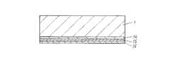
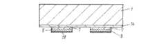
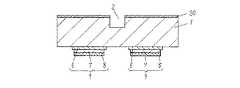
図1は本発明の実施の形態1における成分分離デバイスの構成を示す斜視図であり、図2は図1の成分分離デバイスを裏面より見た斜視図である。また、図3は図1の平面図であり、図4は図3のA−A部における断面図である。 FIG. 1 is a perspective view showing a configuration of a component separation device according to
また、図5〜図8は成分の分離方法を説明するための断面図であり、図9〜図14は成分分離デバイスの製造方法を説明するための断面図である。 5 to 8 are sectional views for explaining a component separation method, and FIGS. 9 to 14 are sectional views for explaining a method for producing a component separation device.
図1〜図4において、1はシリコンからなる基板であり、この基板1の内部には所定の幅と深さを有した流路2を形成しており、さらにこの流路2の両端には流入口3と流出口4を設けている。これによって外部より固形成分と液体成分が混合された混合流体を流入および流出させることができる。また基板1にシリコンを利用することによって、生産性に優れた成分分離デバイスを実現することができる。 1 to 4,
さらに、流路2とアクチュエータ9a、9b、9c、9dを基板1の同一面方向に向けている。これによって成分分離デバイスを効率よく生産することができる。 Further, the
また、基板1の下面側の流路2の両側および平行方向に4つのアクチュエータ9a、9b、9c、9dを設けている。 Also, four
なお、アクチュエータ9は少なくとも一つを設けることにより成分分離デバイスを実現することが可能であるが、複数個のアクチュエータ9を設けることによってその効果をより高めたり、小型の成分分離デバイスを実現することができるという効果を発揮することができる。 In addition, although the component separation device can be realized by providing at least one
このように、流路2を設けた基板1の反対の面にアクチュエータ9a、9b、9c、9dを設けることによって、アクチュエータ9a、9b、9c、9dを流路2と干渉することなく自由に配置することができることから定在波の発生を容易にするとともに、流路2の封止をガラス基板などによって容易に行うことができ、これによって分離の状況を目視で確認しながら成分を分離できる成分分離デバイスを実現することができる。 Thus, by providing the
また、このアクチュエータ9a、9b、9c、9dは基板1に接する順にチタンおよび白金よりなる下部電極6a、6b、6c、6d、チタン酸ジルコン酸鉛からなる圧電体7a、7b、7c、7d、チタンおよび金よりなる上部電極8a、8b、8c、8dから構成している。このような構成のアクチュエータ9a、9b、9c、9dは供給する電力が低電圧であっても大きな変位を実現することができるので、より効率的な加振を行うことができる。さらに、大きな変位を連続して発生させたとしても、密着力に優れた積層構造を実現していることから信頼性においても優れた耐久性を実現できるアクチュエータ9a、9b、9c、9dとしている。また、これらの材料は高精度なパターン形成が可能なことから、流路2に対して高精度な位置にアクチュエータ9a、9b、9c、9dを構成することができ、より効率的な定在波の発生を行うことができることから小型の成分分離デバイスを実現することができる。 The
図1および図2に示すように流路2の両側にアクチュエータ(例えばアクチュエータ9aと9bあるいは9cと9d)を設けることによって、後に述べるように効率的に流路2の内部に定在波を発生させることができる。また、流路2と平行方向にアクチュエータ(例えばアクチュエータ9aと9cあるいは9bと9d)を設けることによって、流路2の内部に異なる周波数の定在波を発生させることができる成分分離デバイスとすることができる。従って、少なくとも複数のアクチュエータ9があればその機能を発揮することができる。 As shown in FIGS. 1 and 2, by providing actuators (for example,
そして、流路2側を除くアクチュエータ9a、9b、9c、9dの周囲に溝5を設けている。図4に示すように、特にこの溝5を完全に貫通する貫通孔の形状に加工することによって定在波のロスをより低減することができ、この溝5を設けることによってアクチュエータ9a、9b、9c、9dで発生させた振動が基板1の周囲に拡散することを抑制し、流路2側へ効率的に集中して伝達することができることから、より強度の強い定在波を発生させることができる。また、隣接したアクチュエータ(例えば9aと9c)を区切るように溝5を形成することによって、隣接したアクチュエータ(例えば9aと9c)を異なる周波数で駆動させた場合において、異なる周波数の振動が干渉しあうことを防ぐことができる。 And the groove |
このように、アクチュエータ9a、9b、9c、9dの流路2側を除く周囲に溝5を形成することによって、アクチュエータ9a、9b、9c、9dで発生した振動が溝5の壁面で反射して流路2側へ伝わることで振動のロスを低減させることができることから、効率の良い成分分離デバイスを実現することができるとともに流路2への振動の制御を容易に行うことのできる成分分離デバイスを実現することができる。 In this way, by forming the
次に、この成分分離デバイスを用いて固形成分と液体成分、または性質の異なる固形成分に分離する分離方法について図5〜図7を用いて説明する。ここで、図5〜図8はそれぞれの成分分離デバイスの流路2近傍を上から見たときの平面図である。 Next, a separation method for separating a solid component from a liquid component or a solid component having different properties using this component separation device will be described with reference to FIGS. Here, FIG. 5 to FIG. 8 are plan views when the vicinity of the
まず、固形成分11と液体成分が混合した流体を流入口3より投入する。この混合した流体は流路2を満たした後、流出口4より流出する。10はこの混合物の流れる方向を示している。通常、何もしない状態では混合流体は固形成分11と液体成分がランダムに流れる。 First, a fluid in which the solid component 11 and the liquid component are mixed is introduced through the
次に、成分の分離方法における基本的な成分分離の動作はアクチュエータ9aに流路2の幅が超音波の波長λの1/2となる周波数の高周波電圧を印加する。そして、このアクチュエータ9aから発生した超音波振動は基板1に伝達されて流路2の内部に流路2に平行して奇数である一つの節を持つ定在波が発生し、前記流路2の内部に流動している各成分は流路2に平行して発生した定在波の節に凝集するようになる。 Next, in the basic component separation operation in the component separation method, a high-frequency voltage having a frequency at which the width of the
さらに、アクチュエータ9bにはアクチュエータ9aに印加する高周波電圧と位相が180度シフトした高周波電圧を印加すると、流路2の内部に一つの節を持つさらに強度の強い定在波を流路2に平行して発生させることができる。このとき、アクチュエータ9aと9cおよびアクチュエータ9bと9dは同じ位相の高周波電圧を印加することによって更に強度の強い定在波を流路2に平行して発生させることができる。この場合、図5に示すように混合流体中の固形成分11は全てこの定在波の節に凝集し、液体成分の流れ12と固体成分の流れ13を作り出すことができる。その後、流出口4より流出した後、液体成分の流れ12と固形成分の流れ13を分岐することで、流路2の壁面側からは液体成分のみを取り出し、流路2の中心からは固形成分11が凝集した混合流体を抽出することができる。このような構成とすることにより、流路2の中心部に固形成分を凝集させることができることから、固形成分の取出しを容易にすることができる小型の成分分離デバイスを実現できるとともに、より低電圧で駆動することができるなど、効率良く成分の分離を行うことができる成分の分離方法を実現することができる。 Further, when a high-frequency voltage applied to the actuator 9a and a high-frequency voltage whose phase is shifted by 180 degrees are applied to the actuator 9b, a stronger standing wave having one node inside the
また、この奇数の定在波を発生させるために流路2の幅が波長λとすると、λ/2、もしくはnλ+λ/2(nは正の整数)となる高周波電圧をアクチュエータ(例えば9a、あるいは9aと9b)に印加することによって流路2に奇数の節を持つ定在波を発生させることができる。このように奇数の節を持つ定在波を発生させることによって固形成分を効率よく分離することができる。 Further, when the width of the
次に、図6に示すようにアクチュエータ9aに流路2の幅が超音波の波長λと同一となる周波数の高周波電圧を印加した場合、流路2の内部に流路2に平行して偶数の2つの節を持つ定在波を発生させることができる。この場合、固体成分の流れ13は2列になって凝集させることができる。 Next, as shown in FIG. 6, when a high frequency voltage having a frequency at which the width of the
また、この偶数の節を持つ定在波を発生させるために流路2の幅が波長λとすると、nλ(nは正の整数)となる高周波電圧をアクチュエータ9aに印加することによって流路2に偶数の節を持つ定在波を流路2に平行して発生させることができる。このような構成とすることによって、図6に示すように流路2の中心部に液体成分の流れ12を、流路2の壁面側に固形成分の流れ13を作り出すことができる。流出口4より流出した後、液体成分の流れ12と固形成分の流れ13を分岐することで、流路2の壁面側からは固形成分11が凝集された混合流体を、流路の中心からは液体成分のみを抽出することができ、効率よく混合流体から液体成分を取り出すことができる。 In addition, when the width of the
また、アクチュエータ9bにアクチュエータ9aに印加する高周波電圧と同位相の高周波電圧を印加することによって、流路2の内部に偶数の2つの節を持つさらに強度の強い定在波を発生させることができるために効率良く混合流体の成分の分離が行えるようになる。 Further, by applying a high-frequency voltage having the same phase as the high-frequency voltage applied to the actuator 9a to the actuator 9b, a standing wave having even two nodes inside the
次に、例えば大きさの異なる粒子を含んだ液体の成分の分離方法について説明する。 Next, for example, a method of separating liquid components containing particles having different sizes will be described.
ここで、定在波の節へ凝集される速度は粒子の性質、例えば粒子の大きさにより異なっており、粒子の大きさが大きくなるほど定在波からの圧力による影響をより強く受け、小さい粒子よりも速く定在波の節に凝集されやすくなるという性質があり、この効果を利用して、前記流路2の内部に偶数個の節を持つ定在波を発生している領域と、奇数個の節を持つ定在波を発生している領域とを形成することにより、液体成分と固形成分、または性質の異なる固形成分を含む混合物を分離することができる。これは偶数個の節を持つ定在波を発生している領域から奇数個の節を持つ定在波を発生している領域へ移るとき、性質の異なる2種類以上の固形成分が定在波の節に集まる速度の違いを利用して、成分を分離する方法である。この成分の分離方法について図7および図8を用いて詳細に説明する。 Here, the speed of aggregation into the nodes of the standing wave varies depending on the nature of the particle, for example, the size of the particle. The larger the particle size, the stronger the influence of the pressure from the standing wave, the smaller the particle. A region where a standing wave is generated having an even number of nodes inside the
まず、図7に示すように大きさの異なる固形成分11a、11bと液体成分が混合した混合流体を流入口3より投入する。このとき、流路2の内部にアクチュエータ9aに流路2の幅が超音波の波長λの1/2となる周波数の高周波電圧を印加することによって流路2内には奇数である一つの節を持つ定在波を発生させることができ、流路2の内部に流動している固形成分は定在波の節に凝集するようになる。そして、アクチュエータ9cに流路2の幅が超音波の波長λと同一となる周波数の高周波電圧を印加することによって、流路2の内部には偶数の2つの節を持つ定在波を発生させることができる。このとき、より定在波の影響を受けやすい大きい固形成分11bが定在波の節に凝集するとともに、小さい固形成分11aは定在波の影響を受けにくい強度となるようにアクチュエータ9cに印加する高周波電圧を制御することによって、図7に示すように、流路2の壁面側に大きい固形成分11bの固形成分の流れ13bと、流路の中心に固形成分11aの固形成分の流れ13aを作り出すことができることから、大きさの異なる固形成分11aと11bを効率よく分離することができる。 First, as shown in FIG. 7, a mixed fluid in which solid components 11 a and 11 b and liquid components having different sizes are mixed is introduced from the
次に、大きさの異なる固形成分11a、11bを分離する別の方法について図8を用いて説明する。その方法は、流路2の内部にアクチュエータ9aに流路2の幅が超音波の波長λと同一となる周波数の高周波電圧を印加することによって、流路2の内部には偶数の2つの節を持つ定在波を発生させ、流路2の内部に流動している成分は定在波の節に凝集するようになる。そして、アクチュエータ9cに流路2の幅が超音波の波長λの1/2となる周波数の高周波電圧を印加することによって、流路2内には奇数である一つの節を持つ定在波を発生させる。このとき、より定在波の影響を受けやすい大きい固形成分11bが定在波の節に凝集するとともに、小さい固形成分11aは定在波の影響を受けにくい強度となるようにアクチュエータ9cに印加する高周波電圧を制御することによって、図8に示すように、流路2の壁面側に小さい固形成分11aの固形成分の流れ13aと、流路の中心に大きい固形成分11bの固形成分の流れ13bを作り出すことができることから、大きさの異なる固形成分11aと11bを効率よく分離することができる。以上説明してきたような構成とすることにより、性質の異なる2種類以上の固形成分が定在波の節に集まる速度の違いを利用して分離することができる成分の分離方法を実現することができる。 Next, another method for separating the solid components 11a and 11b having different sizes will be described with reference to FIG. In the method, by applying a high frequency voltage having a frequency at which the width of the
次に、前記のような構成を有する成分分離デバイスの製造方法について、図面を用いて説明する。図9〜図14は実施の形態1における成分分離デバイスを製造する手順を示した断面図である。 Next, a method for manufacturing a component separation device having the above-described configuration will be described with reference to the drawings. 9 to 14 are cross-sectional views showing a procedure for manufacturing the component separation device in the first embodiment.
まず、図9に示すようにシリコンからなる基板1に、順にチタンおよび白金層14、チタン酸ジルコン酸鉛15、チタンおよび金層16を薄膜技術によって形成する。これらを形成する薄膜形成方法はチタンおよび白金層14およびチタンおよび金層16についてはスパッタリング、蒸着など通常の方法を用いる。 First, as shown in FIG. 9, a titanium and
また、チタン酸ジルコン酸鉛層15についてはスパッタリング法、水熱合成法、ゾルゲル法などを用いることができる。特にスパッタリングによってチタン酸ジルコン酸鉛などを形成すると、圧電特性が高く、安定した変位の得られる圧電薄膜とすることができる。 For the lead zirconate titanate layer 15, a sputtering method, a hydrothermal synthesis method, a sol-gel method, or the like can be used. In particular, when lead zirconate titanate or the like is formed by sputtering, a piezoelectric thin film having high piezoelectric characteristics and stable displacement can be obtained.
次に、図10に示すように所定のパターンにレジストマスク17を形成した後、最上層のチタンおよび金層16をエッチングによってパターニングされた上部電極8を形成する。その後、このレジストマスク17はエッチング後に除去する。 Next, as shown in FIG. 10, after a resist
次に、図11に示すように所定のパターンにレジストマスク18を形成し、チタン酸ジルコン酸鉛15をエッチングして、同様に分割された圧電体7を形成する。その後、このレジストマスク18はエッチング後に除去する。 Next, as shown in FIG. 11, a resist mask 18 is formed in a predetermined pattern, and the lead zirconate titanate 15 is etched to form the
次に、図12に示すように所定のパターンにレジストマスク19を形成し、チタンおよび白金層14をエッチングすることによって下部電極6を形成する。その後、このレジストマスク19はエッチング後に除去する。 Next, as shown in FIG. 12, a resist
次に、図13に示すように基板1の上面に所定のパターンにレジストマスク20を形成し、シリコンからなる基板1をエッチングすることによって、基板1の内部に流路2を形成する。その後、このレジストマスク20はエッチング後に除去する。 Next, as shown in FIG. 13, a resist
次に、図14に示すように所定のパターンにレジストマスク21を形成し、シリコンからなる基板1をエッチングして、基板1に溝5を形成する。このとき、溝5の深さは深いほど定在波のリークが少なくなるので、溝5は貫通孔とすることが望ましい。その後、このレジストマスク21はエッチング後に除去する。 Next, as shown in FIG. 14, a resist
また、図13および図14において、基板1であるシリコンをエッチングする方法としてドライエッチング法を用いることにより、微細な形状の流路2および溝5を高精度に加工することができる。さらに、このドライエッチング法によって加工する際、エッチングを促進するガスとエッチングを抑制するガスを混合させてドライエッチングを行うことにより、より高精度に加工することができる。 In FIGS. 13 and 14, by using a dry etching method as a method for etching silicon which is the
以上の製造方法により、本発明の成分分離デバイスを製造することができる。 The component separation device of the present invention can be manufactured by the above manufacturing method.
(実施の形態2)
以下、本発明の実施の形態における成分分離デバイスについて図面を用いて説明する。(Embodiment 2)
Hereinafter, a component separation device according to an embodiment of the present invention will be described with reference to the drawings.
図15は本発明の実施の形態2における成分分離デバイスの形態を示す断面図であり、特に実施の形態1と異なる点は、基板1であるシリコンに形成した溝5の流路2側の壁面とアクチュエータ9を設けた基板1の面が鋭角となるように形成している点である。このような構成とすることによって、流路2に到達するまでの距離の短い反射波を利用することができるとともに、流路2の壁面への入射角がより鋭角となるため、より効率的な成分の分離ができる成分分離デバイスを実現することができる。 FIG. 15 is a cross-sectional view showing the configuration of the component separation device according to the second embodiment of the present invention. In particular, the difference from the first embodiment is that the wall surface on the
また、このような形状を有する溝5はウエットエッチング法によってシリコンからなる基板1の結晶異方性を利用しながらエッチングすることによって傾斜した壁面を有する基板1を作製することができる。 Moreover, the groove |
本発明は、たとえば、血液、乳液などに代表される、液体成分と固形成分が混合された溶液の成分を、それぞれの成分に分離することができるという効果を有し、成分分離器、成分分析機などに有用である。 The present invention has an effect that, for example, components of a solution in which a liquid component and a solid component are mixed, represented by blood, emulsion, etc., can be separated into respective components, and a component separator, component analysis Useful for machines.
1 基板
2 流路
3 流入口
4 流出口
5 溝
6、6a、6b、6c、6d 下部電極
7、7a、7b、7c、7d 圧電体
8、8a、8b、8c、8d 上部電極
9、9a、9b、9c、9d アクチュエータ
10 混合物の流れ
11、11a、11b 固形成分
12 液体成分の流れ
13、13a、13b 固形成分の流れ
14 チタンおよび白金層
15 チタン酸ジルコン酸鉛
16 チタンおよび金層
17、18、19、20、21 レジストマスクDESCRIPTION OF
Claims (12)
Translated fromJapanesePriority Applications (5)
| Application Number | Priority Date | Filing Date | Title |
|---|---|---|---|
| JP2005126040AJP4770251B2 (en) | 2005-04-25 | 2005-04-25 | Component separation device and component separation method using the same |
| PCT/JP2006/308542WO2006115241A1 (en) | 2005-04-25 | 2006-04-24 | Component separation device and method of separating component |
| CNB2006800002443ACN100475309C (en) | 2005-04-25 | 2006-04-24 | Component separation device and component separation method |
| EP06745620.2AEP1878483B1 (en) | 2005-04-25 | 2006-04-24 | Component separation device and method of separating component |
| US11/721,734US7968049B2 (en) | 2005-04-25 | 2006-04-24 | Component separating device and method of separating component |
Applications Claiming Priority (1)
| Application Number | Priority Date | Filing Date | Title |
|---|---|---|---|
| JP2005126040AJP4770251B2 (en) | 2005-04-25 | 2005-04-25 | Component separation device and component separation method using the same |
Publications (2)
| Publication Number | Publication Date |
|---|---|
| JP2006297333A JP2006297333A (en) | 2006-11-02 |
| JP4770251B2true JP4770251B2 (en) | 2011-09-14 |
Family
ID=37214855
Family Applications (1)
| Application Number | Title | Priority Date | Filing Date |
|---|---|---|---|
| JP2005126040AExpired - Fee RelatedJP4770251B2 (en) | 2005-04-25 | 2005-04-25 | Component separation device and component separation method using the same |
Country Status (5)
| Country | Link |
|---|---|
| US (1) | US7968049B2 (en) |
| EP (1) | EP1878483B1 (en) |
| JP (1) | JP4770251B2 (en) |
| CN (1) | CN100475309C (en) |
| WO (1) | WO2006115241A1 (en) |
Families Citing this family (69)
| Publication number | Priority date | Publication date | Assignee | Title |
|---|---|---|---|---|
| US7340957B2 (en) | 2004-07-29 | 2008-03-11 | Los Alamos National Security, Llc | Ultrasonic analyte concentration and application in flow cytometry |
| JP4984849B2 (en)* | 2006-11-27 | 2012-07-25 | パナソニック株式会社 | Component separation device and chemical analysis device using the component separation device |
| JP5119848B2 (en)* | 2007-10-12 | 2013-01-16 | 富士ゼロックス株式会社 | Microreactor device |
| US8266951B2 (en) | 2007-12-19 | 2012-09-18 | Los Alamos National Security, Llc | Particle analysis in an acoustic cytometer |
| FR2940450B1 (en)* | 2008-12-22 | 2011-02-18 | Centre Nat Rech Scient | DEVICE AND METHOD FOR STUDYING AN ACOUSTIC WAVE STUDY AREA |
| US8691145B2 (en) | 2009-11-16 | 2014-04-08 | Flodesign Sonics, Inc. | Ultrasound and acoustophoresis for water purification |
| JP5118714B2 (en)* | 2010-03-10 | 2013-01-16 | エムエス・ソリューションズ株式会社 | Microfluidic device |
| US8956538B2 (en) | 2010-06-16 | 2015-02-17 | Flodesign Sonics, Inc. | Phononic crystal desalination system and methods of use |
| WO2012017976A1 (en)* | 2010-08-02 | 2012-02-09 | Murata Mitsuo | Apparatus for continuously separating foreign substance from solution |
| US8679338B2 (en) | 2010-08-23 | 2014-03-25 | Flodesign Sonics, Inc. | Combined acoustic micro filtration and phononic crystal membrane particle separation |
| US9421553B2 (en) | 2010-08-23 | 2016-08-23 | Flodesign Sonics, Inc. | High-volume fast separation of multi-phase components in fluid suspensions |
| EP2625522B1 (en)* | 2010-10-05 | 2019-09-25 | ANPAC Bio-Medical Science Co., Ltd. | Micro-devices for disease detection |
| CN103562728B (en) | 2011-03-24 | 2016-08-17 | 安派科生物医学科技有限公司 | Micro element for disease detection |
| US10967298B2 (en) | 2012-03-15 | 2021-04-06 | Flodesign Sonics, Inc. | Driver and control for variable impedence load |
| US9422328B2 (en) | 2012-03-15 | 2016-08-23 | Flodesign Sonics, Inc. | Acoustic bioreactor processes |
| US9752113B2 (en) | 2012-03-15 | 2017-09-05 | Flodesign Sonics, Inc. | Acoustic perfusion devices |
| US10040011B2 (en) | 2012-03-15 | 2018-08-07 | Flodesign Sonics, Inc. | Acoustophoretic multi-component separation technology platform |
| US9688958B2 (en) | 2012-03-15 | 2017-06-27 | Flodesign Sonics, Inc. | Acoustic bioreactor processes |
| US10953436B2 (en) | 2012-03-15 | 2021-03-23 | Flodesign Sonics, Inc. | Acoustophoretic device with piezoelectric transducer array |
| US9416344B2 (en) | 2012-03-15 | 2016-08-16 | Flodesign Sonics, Inc. | Bioreactor using acoustic standing waves |
| US9783775B2 (en) | 2012-03-15 | 2017-10-10 | Flodesign Sonics, Inc. | Bioreactor using acoustic standing waves |
| US9567559B2 (en) | 2012-03-15 | 2017-02-14 | Flodesign Sonics, Inc. | Bioreactor using acoustic standing waves |
| US9950282B2 (en) | 2012-03-15 | 2018-04-24 | Flodesign Sonics, Inc. | Electronic configuration and control for acoustic standing wave generation |
| US10370635B2 (en) | 2012-03-15 | 2019-08-06 | Flodesign Sonics, Inc. | Acoustic separation of T cells |
| US10689609B2 (en) | 2012-03-15 | 2020-06-23 | Flodesign Sonics, Inc. | Acoustic bioreactor processes |
| US9272234B2 (en) | 2012-03-15 | 2016-03-01 | Flodesign Sonics, Inc. | Separation of multi-component fluid through ultrasonic acoustophoresis |
| US10322949B2 (en) | 2012-03-15 | 2019-06-18 | Flodesign Sonics, Inc. | Transducer and reflector configurations for an acoustophoretic device |
| US9458450B2 (en) | 2012-03-15 | 2016-10-04 | Flodesign Sonics, Inc. | Acoustophoretic separation technology using multi-dimensional standing waves |
| US9745548B2 (en) | 2012-03-15 | 2017-08-29 | Flodesign Sonics, Inc. | Acoustic perfusion devices |
| US9752114B2 (en) | 2012-03-15 | 2017-09-05 | Flodesign Sonics, Inc | Bioreactor using acoustic standing waves |
| US9822333B2 (en) | 2012-03-15 | 2017-11-21 | Flodesign Sonics, Inc. | Acoustic perfusion devices |
| US10704021B2 (en) | 2012-03-15 | 2020-07-07 | Flodesign Sonics, Inc. | Acoustic perfusion devices |
| US9340435B2 (en) | 2012-03-15 | 2016-05-17 | Flodesign Sonics, Inc. | Separation of multi-component fluid through ultrasonic acoustophoresis |
| US9796956B2 (en) | 2013-11-06 | 2017-10-24 | Flodesign Sonics, Inc. | Multi-stage acoustophoresis device |
| US9623348B2 (en) | 2012-03-15 | 2017-04-18 | Flodesign Sonics, Inc. | Reflector for an acoustophoretic device |
| US11179747B2 (en) | 2015-07-09 | 2021-11-23 | Flodesign Sonics, Inc. | Non-planar and non-symmetrical piezoelectric crystals and reflectors |
| US10737953B2 (en) | 2012-04-20 | 2020-08-11 | Flodesign Sonics, Inc. | Acoustophoretic method for use in bioreactors |
| US11324873B2 (en) | 2012-04-20 | 2022-05-10 | Flodesign Sonics, Inc. | Acoustic blood separation processes and devices |
| US9725690B2 (en) | 2013-06-24 | 2017-08-08 | Flodesign Sonics, Inc. | Fluid dynamic sonic separator |
| US9745569B2 (en) | 2013-09-13 | 2017-08-29 | Flodesign Sonics, Inc. | System for generating high concentration factors for low cell density suspensions |
| WO2015105955A1 (en) | 2014-01-08 | 2015-07-16 | Flodesign Sonics, Inc. | Acoustophoresis device with dual acoustophoretic chamber |
| US20160332159A1 (en)* | 2014-01-15 | 2016-11-17 | Eth Zurich | Acoustophoretic droplet handling in bulk acoustic wave devices |
| WO2015172095A1 (en) | 2014-05-08 | 2015-11-12 | Flodesign Sonics, Inc. | Acoustophoretic device with piezoelectric transducer array |
| SG11201610712XA (en) | 2014-07-02 | 2017-01-27 | Flodesign Sonics Inc | Acoustophoretic device with uniform fluid flow |
| US9744483B2 (en) | 2014-07-02 | 2017-08-29 | Flodesign Sonics, Inc. | Large scale acoustic separation device |
| WO2016006642A1 (en)* | 2014-07-08 | 2016-01-14 | 国立大学法人東北大学 | Particle manipulation device and method for classifying particles using said device |
| US9675906B2 (en) | 2014-09-30 | 2017-06-13 | Flodesign Sonics, Inc. | Acoustophoretic clarification of particle-laden non-flowing fluids |
| BR112017008429B1 (en) | 2014-10-24 | 2022-08-09 | Life Technologies Corporation | METHOD TO PURIFY A SAMPLE IN A TWO-PHASE SYSTEM AND SAMPLE PURIFICATION SYSTEM |
| CN104671332B (en)* | 2015-02-06 | 2016-08-31 | 徐州工程学院 | A kind of 1,2-dichloropropane piece-rate system and separating technology thereof |
| US10106770B2 (en) | 2015-03-24 | 2018-10-23 | Flodesign Sonics, Inc. | Methods and apparatus for particle aggregation using acoustic standing waves |
| EP3288660A1 (en) | 2015-04-29 | 2018-03-07 | Flodesign Sonics Inc. | Acoustophoretic device for angled wave particle deflection |
| US11377651B2 (en) | 2016-10-19 | 2022-07-05 | Flodesign Sonics, Inc. | Cell therapy processes utilizing acoustophoresis |
| US11021699B2 (en) | 2015-04-29 | 2021-06-01 | FioDesign Sonics, Inc. | Separation using angled acoustic waves |
| US11708572B2 (en) | 2015-04-29 | 2023-07-25 | Flodesign Sonics, Inc. | Acoustic cell separation techniques and processes |
| CA2986238A1 (en) | 2015-05-20 | 2016-11-24 | Bart Lipkens | Acoustic manipulation of particles in standing wave fields |
| US10161926B2 (en) | 2015-06-11 | 2018-12-25 | Flodesign Sonics, Inc. | Acoustic methods for separation of cells and pathogens |
| US9663756B1 (en) | 2016-02-25 | 2017-05-30 | Flodesign Sonics, Inc. | Acoustic separation of cellular supporting materials from cultured cells |
| US11459540B2 (en) | 2015-07-28 | 2022-10-04 | Flodesign Sonics, Inc. | Expanded bed affinity selection |
| US11474085B2 (en) | 2015-07-28 | 2022-10-18 | Flodesign Sonics, Inc. | Expanded bed affinity selection |
| US10710006B2 (en) | 2016-04-25 | 2020-07-14 | Flodesign Sonics, Inc. | Piezoelectric transducer for generation of an acoustic standing wave |
| US11085035B2 (en) | 2016-05-03 | 2021-08-10 | Flodesign Sonics, Inc. | Therapeutic cell washing, concentration, and separation utilizing acoustophoresis |
| US11214789B2 (en) | 2016-05-03 | 2022-01-04 | Flodesign Sonics, Inc. | Concentration and washing of particles with acoustics |
| EP3481361A1 (en) | 2016-05-03 | 2019-05-15 | Flodesign Sonics, Inc. | Therapeutic cell washing, concentration, and separation utilizing acoustophoresis |
| CN105776417A (en)* | 2016-06-01 | 2016-07-20 | 北京中科奥倍超声波技术研究院 | Ultrasonic sewage treatment method implemented through frequency mixing in combination with standing waves |
| JP2020513248A (en) | 2016-10-19 | 2020-05-14 | フロデザイン ソニックス, インク.Flodesign Sonics, Inc. | Affinity cell extraction by sound |
| US11331668B2 (en)* | 2017-08-31 | 2022-05-17 | Acousort Ab | Methods and devices for acoustophoretic operations in polymer chips |
| CN111480345B (en) | 2017-12-14 | 2022-04-29 | 弗洛设计声能学公司 | Acoustophoretic system, method for operating acoustophoretic system, and method for controlling acoustic transducer and acoustic system |
| JP2023105927A (en)* | 2022-01-20 | 2023-08-01 | セイコーエプソン株式会社 | Fluid device and fluid device control method |
| EP4539989A4 (en)* | 2022-06-17 | 2025-08-27 | Siemens Healthcare Diagnostics Inc | ACUSTOPHORESIS DEVICES WITH CONDUCTIVE ELECTRODES AND METHODS |
Family Cites Families (15)
| Publication number | Priority date | Publication date | Assignee | Title |
|---|---|---|---|---|
| AT390739B (en)* | 1988-11-03 | 1990-06-25 | Ewald Dipl Ing Dr Benes | METHOD AND DEVICE FOR SEPARATING PARTICLES DISPERSED IN A DISPERSION AGENT |
| WO1994026390A1 (en)* | 1993-05-11 | 1994-11-24 | Carlson, David, V. | Multilayered piezoelectric resonator for the separation of suspended particles |
| JP3487699B2 (en)* | 1995-11-08 | 2004-01-19 | 株式会社日立製作所 | Ultrasonic treatment method and apparatus |
| JPH09288052A (en)* | 1996-04-24 | 1997-11-04 | Hitachi Ltd | Fractionation device |
| JPH1082723A (en)* | 1996-09-06 | 1998-03-31 | Hitachi Ltd | Particle processing equipment |
| GB9708984D0 (en)* | 1997-05-03 | 1997-06-25 | Univ Cardiff | Particle manipulation |
| JPH11197491A (en)* | 1998-01-13 | 1999-07-27 | Hitachi Ltd | Particle processing method and particle processing apparatus |
| JP2000024431A (en)* | 1998-07-14 | 2000-01-25 | Hitachi Ltd | Particle processing equipment |
| JP2001050940A (en)* | 1999-08-04 | 2001-02-23 | Sekisui Plastics Co Ltd | Ultrasonic transducer |
| JP3846271B2 (en)* | 2001-11-05 | 2006-11-15 | 松下電器産業株式会社 | Thin film piezoelectric element and manufacturing method thereof |
| SE0200860D0 (en)* | 2002-03-20 | 2002-03-20 | Monica Almqvist | Microfluidic cell and method for sample handling |
| JP4505624B2 (en)* | 2002-06-21 | 2010-07-21 | 独立行政法人産業技術総合研究所 | Non-contact filtering method and apparatus using ultrasonic waves |
| JP2004097851A (en)* | 2002-09-04 | 2004-04-02 | Murata Mfg Co Ltd | Ultrasonic vibration apparatus |
| GB0223562D0 (en)* | 2002-10-10 | 2002-11-20 | Secr Defence | Apparatus for moving particles |
| CN100393387C (en)* | 2003-12-17 | 2008-06-11 | 松下电器产业株式会社 | Component separation device, method for producing same, and component separation method using same |
- 2005
- 2005-04-25JPJP2005126040Apatent/JP4770251B2/ennot_activeExpired - Fee Related
- 2006
- 2006-04-24USUS11/721,734patent/US7968049B2/ennot_activeExpired - Fee Related
- 2006-04-24WOPCT/JP2006/308542patent/WO2006115241A1/ennot_activeCeased
- 2006-04-24CNCNB2006800002443Apatent/CN100475309C/ennot_activeExpired - Fee Related
- 2006-04-24EPEP06745620.2Apatent/EP1878483B1/ennot_activeCeased
Also Published As
| Publication number | Publication date |
|---|---|
| EP1878483B1 (en) | 2016-05-25 |
| US20090250406A1 (en) | 2009-10-08 |
| JP2006297333A (en) | 2006-11-02 |
| CN1956765A (en) | 2007-05-02 |
| EP1878483A1 (en) | 2008-01-16 |
| EP1878483A4 (en) | 2012-12-05 |
| US7968049B2 (en) | 2011-06-28 |
| WO2006115241A1 (en) | 2006-11-02 |
| CN100475309C (en) | 2009-04-08 |
Similar Documents
| Publication | Publication Date | Title |
|---|---|---|
| JP4770251B2 (en) | Component separation device and component separation method using the same | |
| Wilson et al. | Phononic crystal structures for acoustically driven microfluidic manipulations | |
| Connacher et al. | Micro/nano acoustofluidics: materials, phenomena, design, devices, and applications | |
| CN102612405B (en) | For fluidics equipment and the fluidics substrate of the surface acoustic wave process of fluid sample | |
| US11209395B2 (en) | Baw sensing and filtration device and related methods | |
| Ding et al. | Surface acoustic wave microfluidics | |
| RU2618890C2 (en) | Acoustophoretic separation of lipid particles from erythrocytes | |
| KR101356933B1 (en) | Apparatus and method for separating micro-nano scale particles using surface acoustic wave-based microfluidic chromatography | |
| US20160325206A1 (en) | Acoustic pre-conditioner | |
| US10371667B2 (en) | BAW sensor with passive mixing structures | |
| US10812045B2 (en) | BAW sensor with enhanced surface area active region | |
| JP4259525B2 (en) | Component separation device, method for producing the same, and component separation method using the same | |
| Qiu et al. | Enhancement of acoustic energy density in bulk-wave-acoustophoresis devices using side actuation | |
| CN102527132A (en) | Fine particle separator | |
| JP4251019B2 (en) | Micro solid component separation device, method for producing the same, and method for separating micro solid component using the same | |
| KR20240053305A (en) | Apparatus and method of surface acoustic wave-based acousto-microfluidic device for residue-free manipulation of microscale objects, and separation/discharge method of microscale objects | |
| Talebjedi | Developing an acoustic-based microfluidics micro/nano scale particle separation and manipulation platform with application for extracellular vesicle isolation | |
| Zaheri-Ghannad et al. | Cell/particle manipulation using Bulk Acoustic Waves (BAWs) on centrifugal microfluidic platforms: A mathematical study | |
| Zhang | Designs of Surface Acoustic Waves for Micro/Nano-scale Particles/Fluid Manipulation | |
| JP4297049B2 (en) | Component separation device, method for producing the same, and method for separating minute solid components using the same | |
| Bruckman | An Acoustophoresis-based Microfluidics Platform for Cell Isolation | |
| Spigarelli | Submicrometer particles separation in acoustofluidic devices | |
| Kolpakov | Two-Dimensional Acoustic Manipulation of Particles in Liquid Media | |
| Mei | Guided Surface Acoustic Wave Device Design and Fabrication for the Application of Cell Agglomeration | |
| WO2025212658A1 (en) | Dynamically reprogrammable acoustofluidic metasurface for subwavelength particle manipulation and assembly |
Legal Events
| Date | Code | Title | Description |
|---|---|---|---|
| A621 | Written request for application examination | Free format text:JAPANESE INTERMEDIATE CODE: A621 Effective date:20080304 | |
| RD01 | Notification of change of attorney | Free format text:JAPANESE INTERMEDIATE CODE: A7421 Effective date:20080414 | |
| RD01 | Notification of change of attorney | Free format text:JAPANESE INTERMEDIATE CODE: A7421 Effective date:20091126 | |
| TRDD | Decision of grant or rejection written | ||
| A01 | Written decision to grant a patent or to grant a registration (utility model) | Free format text:JAPANESE INTERMEDIATE CODE: A01 Effective date:20110524 | |
| A01 | Written decision to grant a patent or to grant a registration (utility model) | Free format text:JAPANESE INTERMEDIATE CODE: A01 | |
| A61 | First payment of annual fees (during grant procedure) | Free format text:JAPANESE INTERMEDIATE CODE: A61 Effective date:20110606 | |
| FPAY | Renewal fee payment (event date is renewal date of database) | Free format text:PAYMENT UNTIL: 20140701 Year of fee payment:3 | |
| R151 | Written notification of patent or utility model registration | Ref document number:4770251 Country of ref document:JP Free format text:JAPANESE INTERMEDIATE CODE: R151 | |
| FPAY | Renewal fee payment (event date is renewal date of database) | Free format text:PAYMENT UNTIL: 20140701 Year of fee payment:3 | |
| LAPS | Cancellation because of no payment of annual fees |