JP4769808B2 - Interface modules used in Fieldbus device networks and Internet-based and non-Internet-based process control networks - Google Patents
Interface modules used in Fieldbus device networks and Internet-based and non-Internet-based process control networksDownload PDFInfo
- Publication number
- JP4769808B2 JP4769808B2JP2007530250AJP2007530250AJP4769808B2JP 4769808 B2JP4769808 B2JP 4769808B2JP 2007530250 AJP2007530250 AJP 2007530250AJP 2007530250 AJP2007530250 AJP 2007530250AJP 4769808 B2JP4769808 B2JP 4769808B2
- Authority
- JP
- Japan
- Prior art keywords
- fieldbus
- process control
- module
- control network
- network
- Prior art date
- Legal status (The legal status is an assumption and is not a legal conclusion. Google has not performed a legal analysis and makes no representation as to the accuracy of the status listed.)
- Expired - Fee Related
Links
Images

Classifications
- G—PHYSICS
- G05—CONTROLLING; REGULATING
- G05B—CONTROL OR REGULATING SYSTEMS IN GENERAL; FUNCTIONAL ELEMENTS OF SUCH SYSTEMS; MONITORING OR TESTING ARRANGEMENTS FOR SUCH SYSTEMS OR ELEMENTS
- G05B19/00—Programme-control systems
- G05B19/02—Programme-control systems electric
- G05B19/418—Total factory control, i.e. centrally controlling a plurality of machines, e.g. direct or distributed numerical control [DNC], flexible manufacturing systems [FMS], integrated manufacturing systems [IMS] or computer integrated manufacturing [CIM]
- G05B19/4185—Total factory control, i.e. centrally controlling a plurality of machines, e.g. direct or distributed numerical control [DNC], flexible manufacturing systems [FMS], integrated manufacturing systems [IMS] or computer integrated manufacturing [CIM] characterised by the network communication
- G05B19/4186—Total factory control, i.e. centrally controlling a plurality of machines, e.g. direct or distributed numerical control [DNC], flexible manufacturing systems [FMS], integrated manufacturing systems [IMS] or computer integrated manufacturing [CIM] characterised by the network communication by protocol, e.g. MAP, TOP
- H—ELECTRICITY
- H04—ELECTRIC COMMUNICATION TECHNIQUE
- H04L—TRANSMISSION OF DIGITAL INFORMATION, e.g. TELEGRAPHIC COMMUNICATION
- H04L12/00—Data switching networks
- H04L12/28—Data switching networks characterised by path configuration, e.g. LAN [Local Area Networks] or WAN [Wide Area Networks]
- H04L12/40—Bus networks
- H04L12/40006—Architecture of a communication node
- H04L12/40013—Details regarding a bus controller
- G—PHYSICS
- G05—CONTROLLING; REGULATING
- G05B—CONTROL OR REGULATING SYSTEMS IN GENERAL; FUNCTIONAL ELEMENTS OF SUCH SYSTEMS; MONITORING OR TESTING ARRANGEMENTS FOR SUCH SYSTEMS OR ELEMENTS
- G05B2219/00—Program-control systems
- G05B2219/30—Nc systems
- G05B2219/31—From computer integrated manufacturing till monitoring
- G05B2219/31122—Bridge between networks
- G—PHYSICS
- G05—CONTROLLING; REGULATING
- G05B—CONTROL OR REGULATING SYSTEMS IN GENERAL; FUNCTIONAL ELEMENTS OF SUCH SYSTEMS; MONITORING OR TESTING ARRANGEMENTS FOR SUCH SYSTEMS OR ELEMENTS
- G05B2219/00—Program-control systems
- G05B2219/30—Nc systems
- G05B2219/31—From computer integrated manufacturing till monitoring
- G05B2219/31138—Profibus process fieldbus
- G—PHYSICS
- G05—CONTROLLING; REGULATING
- G05B—CONTROL OR REGULATING SYSTEMS IN GENERAL; FUNCTIONAL ELEMENTS OF SUCH SYSTEMS; MONITORING OR TESTING ARRANGEMENTS FOR SUCH SYSTEMS OR ELEMENTS
- G05B2219/00—Program-control systems
- G05B2219/30—Nc systems
- G05B2219/31—From computer integrated manufacturing till monitoring
- G05B2219/31326—Database to manage communication networks
- G—PHYSICS
- G05—CONTROLLING; REGULATING
- G05B—CONTROL OR REGULATING SYSTEMS IN GENERAL; FUNCTIONAL ELEMENTS OF SUCH SYSTEMS; MONITORING OR TESTING ARRANGEMENTS FOR SUCH SYSTEMS OR ELEMENTS
- G05B2219/00—Program-control systems
- G05B2219/30—Nc systems
- G05B2219/31—From computer integrated manufacturing till monitoring
- G05B2219/31335—Database of address of devices registers in different networks, mapping
- H—ELECTRICITY
- H04—ELECTRIC COMMUNICATION TECHNIQUE
- H04L—TRANSMISSION OF DIGITAL INFORMATION, e.g. TELEGRAPHIC COMMUNICATION
- H04L12/00—Data switching networks
- H04L12/28—Data switching networks characterised by path configuration, e.g. LAN [Local Area Networks] or WAN [Wide Area Networks]
- H04L12/40—Bus networks
- H04L2012/40208—Bus networks characterized by the use of a particular bus standard
- H04L2012/40221—Profibus
- Y—GENERAL TAGGING OF NEW TECHNOLOGICAL DEVELOPMENTS; GENERAL TAGGING OF CROSS-SECTIONAL TECHNOLOGIES SPANNING OVER SEVERAL SECTIONS OF THE IPC; TECHNICAL SUBJECTS COVERED BY FORMER USPC CROSS-REFERENCE ART COLLECTIONS [XRACs] AND DIGESTS
- Y02—TECHNOLOGIES OR APPLICATIONS FOR MITIGATION OR ADAPTATION AGAINST CLIMATE CHANGE
- Y02P—CLIMATE CHANGE MITIGATION TECHNOLOGIES IN THE PRODUCTION OR PROCESSING OF GOODS
- Y02P90/00—Enabling technologies with a potential contribution to greenhouse gas [GHG] emissions mitigation
- Y02P90/02—Total factory control, e.g. smart factories, flexible manufacturing systems [FMS] or integrated manufacturing systems [IMS]
Landscapes
- Engineering & Computer Science (AREA)
- Computer Networks & Wireless Communication (AREA)
- Signal Processing (AREA)
- General Engineering & Computer Science (AREA)
- Manufacturing & Machinery (AREA)
- Quality & Reliability (AREA)
- Physics & Mathematics (AREA)
- General Physics & Mathematics (AREA)
- Automation & Control Theory (AREA)
- Small-Scale Networks (AREA)
- Programmable Controllers (AREA)
- Communication Control (AREA)
- Control By Computers (AREA)
Description
Translated fromJapanese本発明は、一般的にプロセス制御システムに関するものであり、さらに詳細には、Fieldbusデバイスネットワークとインターネットベースおよび非インターネットベースのプロセス制御ネットワークとの間においてデータを交換するためのインターフェイスモジュールに関するものである。 The present invention relates generally to process control systems, and more particularly to an interface module for exchanging data between a Fieldbus device network and Internet-based and non-Internet-based process control networks. .
化学プロセス、石油プロセスまたは他のプロセスにおいて利用されているプロセス制御システムは、アナログバスおよび/もしくはデジタルバスまたは他の通信回線もしくは通信チャネルを介して、少なくとも一つのホストワークステーションまたはオペレータワークステーションと通信可能に接続されている少なくとも一つの集中型プロセスコントローラを備えているのが普通である。これらのフィールドデバイスは、たとえばバルブ、バルブポジショナ、スイッチ、トランスミッタ(たとえば、温度センサ、圧力センサおよび流量センサ)等であり、バルブの開閉およびプロセスパラメータの測定の如きプロセス内の機能を実行するようになっている。プロセスコントローラは、入力/出力デバイスを通じて、フィールドデバイスにより作成されるプロセス測定値および/またはそのフィールドデバイスに関連する他の情報を表す信号を受信し、この情報を利用して制御ルーチンを実行し、制御信号を生成する。これらの制御信号は、プロセスの動作を制御するために、バスまたは他の通信チャネルを通じてフィールドデバイスに送信される。これらのフィールドデバイスおよびコントローラからの情報は、通常、オペレータワークステーションにより実行される一または複数のアプリケーションによる利用が可能となされており、これにより、オペレータは、プロセスの現在の状況の閲覧、プロセスの動作の変更、プロセスの設定、プロセスのドキュメント化などの如きプロセスに対する所望の操作を実行することができる。 Process control systems utilized in chemical processes, petroleum processes or other processes communicate with at least one host workstation or operator workstation via an analog and / or digital bus or other communication line or channel. It is common to have at least one centralized process controller that is operatively connected. These field devices are, for example, valves, valve positioners, switches, transmitters (eg temperature sensors, pressure sensors and flow sensors), etc., to perform functions in the process such as opening and closing valves and measuring process parameters. It has become. The process controller receives, through the input / output device, signals representing process measurements created by the field device and / or other information associated with the field device, and uses this information to execute control routines; Generate a control signal. These control signals are sent to the field device over a bus or other communication channel to control the operation of the process. Information from these field devices and controllers is usually made available to one or more applications executed by the operator workstation, which allows the operator to view the current status of the process, Desired operations on the process, such as behavior changes, process settings, process documentation, etc., can be performed.
過去十年間くらいで、マイクロプロセッサおよびメモリを有するスマートフィールドデバイスがプロセス制御分野において広く行き渡るようになった。スマートフィールドデバイスは、プロセス内において主要機能を実行することに加えて、デバイスに関するデータを格納し、アナログ形式またはデジタルおよびアナログを組み合わせた形式でコントローラと通信し、自己校正、識別、診断などの如き二次的なタスクを実行しうる。異なる製造業者により製造されたスマートフィールドデバイスを同一のプロセス制御ネットワーク内において一緒に用いることができるように、HART(登録商標)プロトコル、PROFIBUS(登録商標)プロトコル、アクチュエータ・センサ・インターフェイス(以下、「ASインターフェイス」または「ASI」と呼ぶ)プロトコル、WORLDFIP(登録商標)プロトコル、Device−Net(登録商標)プロトコル、CANプロトコルおよびFOUNDATION(商標)Fieldbus(以下、「Fieldbus」と呼ぶ)プロトコルの如き複数の標準型および開放型のスマートデバイス通信プロトコルが開発されている。これらのプロセス制御ネットワークは、FOUNDATION(商標)Fieldbus over High Speed Internet、Modbus TCP、ProfiNetおよびOPCの如きインターネットベースのプロトコルならびにModbus、Profibus DP、DeviceNet、HART(登録商標)、CAN Openなどの如き非インターネットベースのプロトコルを用いて実現されても良い。 In the past decade or so, smart field devices with microprocessors and memory have become widespread in the process control field. In addition to performing key functions within the process, the smart field device stores data about the device and communicates with the controller in analog or digital and analog formats, such as self-calibration, identification, and diagnostics. Can perform secondary tasks. To allow smart field devices manufactured by different manufacturers to be used together in the same process control network, the HART® protocol, PROFIBUS® protocol, actuator sensor interface (hereinafter “ AS protocol ”(referred to as“ AS interface ”or“ ASI ”) protocol, WORLDFIP® protocol, Device-Net® protocol, CAN protocol and FOUNDATION ™ Fieldbus (hereinafter referred to as“ Fieldbus ”) protocol. Standard and open smart device communication protocols have been developed. These process control networks include Internet-based protocols such as FOUNDATION (TM) Fieldbus over High Speed Internet, Modbus TCP, ProfiNet and OPC as well as Modbus, Profibus DP, DeviceNet, HART (registered trademark), HART It may be implemented using a base protocol.
このようなスマートフィールドデバイス用の1つの標準型プロトコルとして、Profibus DPプロトコルが挙げられる。Profibus DPプロトコルには、コントローラが、通信するネットワークのタイプにかかわらずに、認識し、用いるメッセージ構造が規定されている。それは、メッセージ欄の配置および内容に関する共通のフォーマットを定めている。Profibus DPにより、コントローラが他のデバイスへのアクセスを要求する方法、コントローラおよびデバイスが要求に応答する方法およびエラーを検出して報告する方法が定められている。Profibus DPネットワーク上での通信時、各々のコントローラまたはデバイスが、そのデバイスのアドレスを知る方法、それ宛のメッセージを認識する方法、メッセージに含まれているサービスコードに基づいて講じられる処置の種類を決定する方法、および、メッセージに含まれている任意のデータまたは他の情報を抽出する方法は、プロトコルに従って決定される。返事が必要な場合、スレーブデバイスが、Profibus DPプロトコルに従って、回答メッセージを作成し、それをマスターデバイスへ送るようになっている。Profibus DPプロトコルは、当該技術分野において公知になっており、とりわけProfibus DPプロトコルを用いるデバイスの製造業者により、公表され、分配され、入手可能とされている多数の文献、パンフレットおよび仕様書に詳細に記載されている。したがって、Profibus DP通信プロトコルを、本発明に関連する範囲を越えて詳細に記載しない。 One standard protocol for such smart field devices is the Profibus DP protocol. The Profibus DP protocol defines a message structure that the controller recognizes and uses regardless of the type of network it communicates with. It defines a common format for the arrangement and content of message fields. Profibus DP defines how the controller requests access to other devices, how the controller and devices respond to requests, and how to detect and report errors. When communicating on the Profibus DP network, each controller or device knows the address of the device, the method of recognizing the message addressed to it, and the type of action taken based on the service code included in the message. The method of determining and extracting any data or other information contained in the message is determined according to the protocol. When a reply is required, the slave device creates an answer message according to the Profibus DP protocol and sends it to the master device. The Profibus DP protocol is known in the art, and is described in detail in numerous publications, brochures and specifications made publicly, distributed and available by manufacturers of devices that use the Profibus DP protocol. Are listed. Accordingly, the Profibus DP communication protocol is not described in detail beyond the scope relevant to the present invention.
Profibus DPでは、コントローラとフィールドデバイスとの間の情報を交換するためにマスター・スレーブ質問応答サイクルが用いられている。各デバイスには、0と125と間の範囲のアドレスが割り当てられている。一方のデバイス、たとえばマスターは、他方のデバイス、たとえばスレーブ宛てのメッセージを送信することにより、質問、設定値変更、診断などの如き処理を開始するようになっている。Profibus DPプロトコル下では、マスターにより送信されるメッセージは、スレーブデバイスのデバイス住所、要求される取引を定義するサービスコード、スレーブデバイスに送信されるデータおよびエラーチェック情報を含むように書式が設定されている。スレーブデバイスは、メッセージ内の住所に基づいてマスターからのメッセージを検出および受信し、メッセージ内のサービスコードにより示されている取引またはサービスを処理する。取引を処理したまたは要求されたサービスを実行したあと、スレーブデバイスは、講じられた処置の確認情報、マスターに戻されるデータおよびエラーチェック情報を有している、Profibus DPプロトコルに従って作成された応答メッセージを送信する。個々のメッセージに加えて、マスターは、メッセージを定義されたスレーブデバイスのグループへ送信しても良いし(多重通信(multi−cast))、または、メッセージを接続されているすべてのスレーブデバイスへ放送(broadcast)しても良い。マスターは、アドレス127を用いて、また、多重通信メッセージの場合には、目標とされるスレーブデバイスのグループに対して任意に選択したグループ番号を用いて、グローバル制御メッセージとして、放送メッセージおよび多重通信メッセージを送信するようになっている。スレーブデバイスは、個別に宛てられたメッセージに対して応答するものの、マスターデバイスからの放送メッセージまたは多重通信メッセージに対しては応答しない。 In Profibus DP, a master / slave question answering cycle is used to exchange information between the controller and field devices. Each device is assigned an address in the range between 0 and 125. One device, such as a master, starts a process such as a question, a setting value change, or a diagnosis by transmitting a message addressed to the other device, such as a slave. Under the Profibus DP protocol, messages sent by the master are formatted to include the device address of the slave device, the service code that defines the requested transaction, the data sent to the slave device, and error checking information. Yes. The slave device detects and receives a message from the master based on the address in the message and processes the transaction or service indicated by the service code in the message. After processing the transaction or performing the requested service, the slave device has a response message created in accordance with the Profibus DP protocol, with confirmation information of the action taken, data returned to the master and error check information Send. In addition to individual messages, the master may send the message to a defined group of slave devices (multi-cast) or broadcast the message to all connected slave devices. (Broadcast). The master uses the address 127 and, in the case of a multiplex communication message, a broadcast message and multiplex communication as a global control message using a group number arbitrarily selected for the target slave device group. A message is sent. The slave device responds to individually addressed messages, but does not respond to broadcast messages or multiplex communication messages from the master device.
データは、サービスアクセスポイントを利用して、Profibus DPネットワークのデバイス間で交換されるようになっている。各Profibus DPデバイスは、デバイスに関連する指定されたプロセス制御パラメータのセットを有する特徴を備えている。また、Profibus DPネットワーク内で用いられる各プロセス制御パラメータは、一連の利用可能なサービスアクセスポイントから対応するサービスアクセスポイントを割り当てられる。Profibus DPネットワーク内のデバイスは、割り当てられたサービスアクセスポイントに応じて、プロセス制御パラメータを格納および交換するように構成されている。スレーブデバイスからプロセス制御パラメータの値を取得するために、マスターデバイスは、スレーブデバイスのアドレスおよびプロセス制御パラメータのためのサービスアクセスポイントを含む要求メッセージの書式を設定し、送信する。要求メッセージを受信すると、スレーブデバイスは、サービスアクセスポイントの現在値を読み込み、書式を設定し、サービスアクセスポイントおよびその格納された値を備えた応答メッセージを転送する。非インターネットベースプロトコルの他の具体例は、Modbusプロトコルである。Modbusプロトコルは、2003年1月30日に出願された同時係属中の米国特許出願第10/354,525号においてより詳細に記載されている。本出願は、この米国特許出願第10/354,525号に基づいて優先権を主張しているとともに、その内容を、本明細書において参照することにより明示的に援用するものとする。 Data is exchanged between devices of the Profibus DP network using a service access point. Each Profibus DP device has a feature that has a specified set of process control parameters associated with the device. Each process control parameter used in the Profibus DP network is assigned a corresponding service access point from a series of available service access points. Devices in the Profibus DP network are configured to store and exchange process control parameters depending on the assigned service access point. To obtain the value of the process control parameter from the slave device, the master device formats and sends a request message that includes the address of the slave device and a service access point for the process control parameter. Upon receiving the request message, the slave device reads the current value of the service access point, formats it, and forwards a response message with the service access point and its stored value. Another example of a non-Internet based protocol is the Modbus protocol. The Modbus protocol is described in more detail in copending US patent application Ser. No. 10 / 354,525, filed Jan. 30, 2003. This application claims priority based on this US patent application Ser. No. 10 / 354,525, the contents of which are expressly incorporated herein by reference.
一般的にいえば、Fieldbusプロトコルは、総デジタル式のシリアル双方向通信プロトコルである。このプロトコルは、フィールドデバイスを相互に接続する2線式のループもしくはバスに、標準型物理インターフェイスを供する。実際、Fieldbusプロトコルは、あるプロセス内のフィールドデバイスのためのローカルエリアネットワークを提供している。このことにより、プロセス設備全体にわたって分配されている位置において(機能ブロックを用いて)プロセス制御機能を実行することおよび総合的な制御戦略を実行するためにこれらのプロセス制御機能の実行の前後に互いと通信することができるようになる。Fieldbusプロトコルは、当該技術分野において公知になっており、とりわけFieldbus財団により出版、分配および入手可能とされている多数の文献、パンフレットおよび仕様書に詳細に記述されている。Fieldbus財団とは、テキサス州のオースティンに本部を置く非営利組織のことである。したがって、Fieldbusプロトコルの詳細を、本発明に関連する範囲を越えて詳細に記載しない。 Generally speaking, the Fieldbus protocol is an all-digital serial bidirectional communication protocol. This protocol provides a standard physical interface to a two-wire loop or bus that interconnects field devices. In fact, the Fieldbus protocol provides a local area network for field devices within a process. This allows the process control functions to be performed (using functional blocks) at locations distributed throughout the process equipment and before and after the execution of these process control functions to execute the overall control strategy. You will be able to communicate with. The Fieldbus protocol is known in the art and is described in detail in numerous documents, brochures, and specifications that have been published, distributed and made available by the Fieldbus Foundation, among others. The Fieldbus Foundation is a non-profit organization headquartered in Austin, Texas. Therefore, the details of the Fieldbus protocol are not described in detail beyond the scope relevant to the present invention.
Fieldbusプロセス制御ネットワークは、バスを通じて、リンクされている一または複数の相互に連結されたFieldbusセグメントを備えうる。各セグメントは、一または複数のフィールドデバイスを有している。通信を生じさせるために、バスの各セグメント上のデバイスのうちの1つは、バスの対応するセグメント上の通信を能動的にスケジュールに入れて制御するリンクアクティブスケジューラ(LAS)として動作する。バスの各セグメントのLASは、各デバイスの各機能ブロックがバス上で周期的に通信活動を開始するようスケジュールに入れられている時刻およびこの通信活動が発生する時間を含む通信スケジュール(リンクアクティブスケジュール)を格納および更新する。また、LASは、非同期通信がバスセグメント上で起こっていないときに発生しうる非同期通信活動を制御しうる。同期通信が起こっていない間、各フィールドデバイスは、LASからのパストークンメッセージを受信すると、非同期な方法でアラームデータ、閲覧データなどを送信することを順番に許可される。 A Fieldbus process control network may comprise one or more interconnected Fieldbus segments that are linked through a bus. Each segment has one or more field devices. To cause communication, one of the devices on each segment of the bus operates as a link active scheduler (LAS) that actively schedules and controls communication on the corresponding segment of the bus. The LAS for each segment of the bus is a communication schedule (link active schedule) that includes the time at which each functional block of each device is scheduled to periodically initiate communication activity on the bus and the time that this communication activity occurs. ) Is stored and updated. The LAS may also control asynchronous communication activity that may occur when asynchronous communication is not occurring on the bus segment. While no synchronous communication is occurring, each field device is sequentially allowed to transmit alarm data, browsing data, etc. in an asynchronous manner upon receipt of a pass token message from the LAS.
Fieldbusプロトコル下では、フィールドデバイスは、各フィールドデバイスに割り当てられている固有のアドレスを用いて、バス上に互いに通信することができる。フィールドデバイスはバスのノードに取り付けられている。また、各ノードは、プロセス制御ネットワーク内のその他のフィールドデバイスとの通信に用いるために、各ノードに取り付けられたフィールドデバイスを識別すべく割り当てられている物理アドレスを備えている。フィールドデバイス用の固有のアドレスは、バス上のデバイスにより発行されるメッセージに含まれている。メッセージの発行先にあたる一または複数のフィールドデバイスは、それが接続されているバスセグメントをリッスン(listen)して、発行元のフィールドデバイスのアドレスを含んでいるメッセージを取得するように構成されている。登録されているフィールドデバイスが発行元のフィールドデバイスのアドレスを含んだメッセージを検出すると、これらの登録されているフィールドデバイスは、プロセス制御を達成するにあたって必要なメッセージを復号して処理する。 Under the Fieldbus protocol, field devices can communicate with each other on the bus using a unique address assigned to each field device. Field devices are attached to bus nodes. Each node also has a physical address assigned to identify the field device attached to each node for use in communication with other field devices in the process control network. The unique address for the field device is included in the message issued by the device on the bus. One or more field devices to which the message is issued are configured to listen to the bus segment to which it is connected to obtain a message containing the address of the issuing field device. . When the registered field device detects a message including the address of the issuing field device, these registered field devices decode and process the message necessary to achieve process control.
フィールドデバイスは、各フィールドデバイスに定義されている3つのタイプの仮想通信路(VCR)のうちの1つを用いて、バス上でデータおよびメッセージを発行または送信することができる。クライアント/サーバ型のVCRは、バス上のデバイス間において、ユーザにより開始される、スケジュールに入っていない、待機型の、1対1の通信に用いられる。フィールドデバイスは、バス上の他のデバイスに要求メッセージを送信するためにLASからパストークンメッセージを受信するときに、クライアント/サーバ型のVCRを用いうる。依頼人が「クライアント」と呼ばれ、要求メッセージを受信する側のデバイスが「サーバ」と呼ばれる。サーバは、LASからパストークンメッセージを受信し、クライアントの要求を処理するとき、返事を送信する。クライアント/サーバVCRは、たとえば設定値変更、チューニングパラメータのアクセスおよび変更、アラームの了承ならびにデバイスのアップロードおよびダウンロードの如きオペレータ始動要求を実施するために用いられる。 A field device can issue or send data and messages on the bus using one of three types of virtual communication paths (VCRs) defined for each field device. Client / server VCRs are used for unscheduled, standby, one-to-one communications initiated by the user between devices on the bus. A field device may use a client / server type VCR when receiving a pass token message from the LAS to send a request message to other devices on the bus. The client is called a “client”, and the device that receives the request message is called a “server”. The server receives the pass token message from the LAS and sends a reply when processing the client request. The client / server VCR is used to perform operator-initiated requests such as setting value changes, tuning parameter access and changes, alarm acknowledgments and device uploads and downloads.
レポート配布VCRは、ユーザにより開始される、スケジュールに入っていない、待機型の、1対多の通信に用いられる。たとえば、イベントレポートまたはトレンドレポートを有しているあるフィールドデバイスがLASからパストークンを受信すると、そのフィールドデバイスは、デバイス内に規定された「グループアドレス」へそのメッセージを送信する。そのVCRをリッスンするように構成されたデバイスはレポートを受信する。通常、レポート配布VCRタイプは、オペレータコンソールへアラーム通知を送信するためにFieldbusデバイスにより用いられる。 The report distribution VCR is used for non-scheduled, standby type one-to-many communications initiated by the user. For example, when a field device with an event report or trend report receives a pass token from the LAS, the field device sends the message to a “group address” defined in the device. A device configured to listen to that VCR receives the report. Typically, the report distribution VCR type is used by the Fieldbus device to send alarm notifications to the operator console.
最後に、発行者/登録者VCRタイプは、バッファ付きの1対多の通信に用いられる。バッファ付きの通信は、データの最新のバージョンだけを格納し、送信する通信であるため、新しいデータは完全に前のデータに上書きされる。機能ブロックの出力は、たとえばバッファされたデータを含んでいる。「発行者」側フィールドデバイスは、発行者側デバイスがLASまたは登録者デバイスから強要的なデータメッセージ(compel data messaga)を受信すると、バス上の「登録者」フィールドデバイスのすべてに対して、発行者/登録者VCRタイプを用いてメッセージを発行するかまたは放送する。発行者/登録者の関係は、前もって決められ、各フィールドデバイス内に規定、格納されている。Profibus DPおよびFieldbusと同様に、他のプロトコルは、スマートフィールドデバイスに情報を交換させプロセス制御戦略を実施させることを可能とするための通信戦略を提供するようになっている。 Finally, the issuer / registrant VCR type is used for buffered one-to-many communications. Since buffered communication is a communication that stores and transmits only the latest version of data, the new data is completely overwritten by the previous data. The output of the functional block includes, for example, buffered data. When the issuer-side field device receives a compulsory data message from the LAS or registrant device, the “issuer” -side field device issues an issue to all of the “registrant” field devices on the bus. Issue / broadcast message using subscriber / registrant VCR type. The issuer / registrant relationship is predetermined and defined and stored in each field device. Similar to Profibus DP and Fieldbus, other protocols are designed to provide communication strategies that allow smart field devices to exchange information and implement process control strategies.
上述のように、ここ十年程の間、Profibusプロトコル DPプロトコル、ModbusプロトコルおよびFieldbusプロトコルの如き非インターネットベースのプロトコルならびにインターネットベースのプロトコルが、プロセス制御システムにおいて用いられている。その結果、Fieldbusプロトコルに従うプロセス制御ネットワークが同一のプラントまたは設備の中で他のプロトコルに従うプロセス制御ネットワークと共存しうる条件が発生しうる。たとえば、Profibus DPプロトコルの下で動作している現在のプロセス制御システムを備えた設備が、Fieldbusプロトコルにより支援可能なある制御戦略または制御機能を実行するために、プロセス制御ネットワークのうちの一部をFieldbusプロトコルの下で動作するように変換しうる。しかしながら、部分転換にもかかわらず、プロセス制御ネットワークのProfibus DP部分は、依然としてプロセス制御ネットワークのFieldbus部分からの情報およびデータを要求しうる。さらなる具体例としては、既存のプロセス制御ネットワークがProfibus DPプロトコルの下で動作しているプラントまたは設備が、プロセス制御ネットワークがFieldbusプロトコルの下で動作しているプロセスをさらに含むように拡張されうる。または、その逆もありうる。さらに、前記の設備は、プロセス制御ネットワークがインターネットベースのプロトコルの下で動作している他のプロセスを含みうる。先の例と同様に、Fieldbusネットワーク、Profibus DPネットワークおよびインターネットベースのネットワークの間においてデータおよび情報を伝達することが必要となりうる。現在の実施形態では、これらの異なるプロセス制御ネットワーク間においてデータを伝達することができない。したがって、さまざまなネットワークからの情報およびデータをそれらのネットワーク内のデバイス間で伝達することを可能とするために、異なるプロトコルに従うプロセス制御ネットワーク間に接続されうるインターフェイスモジュールの必要性が存在している。 As mentioned above, for the past decade or so, non-Internet based protocols such as the Profibus protocol DP protocol, Modbus protocol and Fieldbus protocol and Internet based protocols have been used in process control systems. As a result, a condition may arise in which a process control network according to the Fieldbus protocol can coexist with a process control network according to another protocol in the same plant or facility. For example, a facility with a current process control system operating under the Profibus DP protocol may use a portion of the process control network to execute a control strategy or control function that can be supported by the Fieldbus protocol. It can be converted to operate under the Fieldbus protocol. However, despite the partial conversion, the Profibus DP portion of the process control network may still request information and data from the Fieldbus portion of the process control network. As a further example, a plant or facility in which an existing process control network is operating under the Profibus DP protocol can be extended such that the process control network further includes a process operating under the Fieldbus protocol. Or vice versa. Furthermore, the facility may include other processes in which the process control network is operating under an Internet-based protocol. Similar to the previous example, it may be necessary to transfer data and information between the Fieldbus network, the Profibus DP network and the Internet-based network. In the current embodiment, data cannot be communicated between these different process control networks. Thus, there is a need for an interface module that can be connected between process control networks that follow different protocols to allow information and data from various networks to be communicated between devices in those networks. .
ネットワーク間のプロセス制御情報の交換を促進するために、Fieldbusプロセス制御ネットワークおよび少なくとも1つの非Fieldbusプロセス制御ネットワークに、インターフェイスモジュールが作用可能に接続されている。インターフェイスモジュールは、Fieldbusプロセス制御ネットワークのフィールドデバイス内の機能ブロックのプロセス制御パラメータが、非Fieldbusプロセス制御ネットワークの対応するプロセス制御パラメータにマッピングされているデータベースを格納するようになっている。一旦Fieldbusプロセス制御パラメータが非Fieldbusプロセス制御パラメータにマッピングされると、インターフェイスモジュールは、Fieldbusプロセス制御ネットワーク上で、プロセス制御パラメータの現在値を求める要求メッセージをFieldbusフィールドデバイスに向けて送信し、インターフェイスモジュールから、Fieldbusフィールドデバイスからプロセス制御パラメータの現在値を含んでいる応答メッセージを受信し、プロセス制御パラメータの現在値をサービスアクセスポイントデータベースに格納するように構成されている。また、インターフェイスモジュールは、他の方向に向かって機能し、非Fieldbusプロセス制御パラメータを、対応するFieldbusプロセス制御パラメータにマッピングしても良い。 An interface module is operatively connected to the Fieldbus process control network and at least one non-Fieldbus process control network to facilitate the exchange of process control information between the networks. The interface module is adapted to store a database in which process control parameters of functional blocks in field devices of the Fieldbus process control network are mapped to corresponding process control parameters of the non-Fieldbus process control network. Once the Fieldbus process control parameter is mapped to the non-Fieldbus process control parameter, the interface module sends a request message for the current value of the process control parameter to the Fieldbus field device on the Fieldbus process control network. A response message including the current value of the process control parameter from the Fieldbus field device and storing the current value of the process control parameter in the service access point database. The interface module may also function in the other direction and map non-Fieldbus process control parameters to corresponding Fieldbus process control parameters.
非Fieldbusプロセス制御ネットワーク内のフィールドデバイスは、Fieldbusプロセス制御パラメータがマッピングされた非Fieldbusプロセス制御パラメータの現在値を求める要求メッセージをインターフェイスモジュールに向けて送信することにより、Fieldbusプロセス制御パラメータの値を取得しても良い。要求を受信すると、インターフェイスモジュールは、Fieldbusプロセス制御パラメータの値を取得するために、非Fieldbusプロセス制御パラメータに対応するデータベース項目を読み込むようになっている。インターフェイスモジュールは、非Fieldbusプロセス制御パラメータとデータベースからのそれに対応するFieldbusプロセス制御パラメータの値を含んでいる応答を書式を合わせて作成し、要求元の非Fieldbusフィールドデバイスに向けて送信する。Fieldbusプロセス制御パラメータを非Fieldbusプロセス制御パラメータに関連付けするようにデータベースを設定するために、インターフェイスモジュールは、パーソナルコンピュータの如きユーザインターフェイスを接続しうるインターネット接続を備えうる。サービスアクセスポイントデータベースの設定プロセスのためのグラフィカルインターフェイスを提供すべく、インターフェイスモジュールのウェブサーバソフトウェアおよびユーザインターフェイスのウェブブラウザソフウェアが用いられうる。 A field device in the non-Fieldbus process control network obtains the value of the Fieldbus process control parameter by sending a request message for the current value of the non-Fieldbus process control parameter to which the Fieldbus process control parameter is mapped to the interface module. You may do it. Upon receipt of the request, the interface module is adapted to read the database item corresponding to the non-Fieldbus process control parameter to obtain the value of the Fieldbus process control parameter. The interface module creates a formatted response that includes the value of the non-Fieldbus process control parameter and the corresponding Fieldbus process control parameter from the database and sends it to the requesting non-Fieldbus field device. In order to configure the database to associate Fieldbus process control parameters with non-Fieldbus process control parameters, the interface module may comprise an internet connection to which a user interface such as a personal computer may be connected. To provide a graphical interface for the service access point database configuration process, the interface module web server software and user interface web browser software may be used.
1つの態様では、本発明は、複数のFieldbusフィールドデバイスを有するFieldbusプロセス制御ネットワークと、複数の非Fieldbusフィールドデバイスを有する少なくとも1つの第一の非Fieldbusプロセス制御ネットワークとを備えているプロセス制御システムに用いられるインターフェイスモジュールに関するものである。インターフェイスモジュールは、Fieldbusプロセス制御ネットワークを第一の非Fieldbusプロセス制御ネットワークに作用可能に接続しうるし、また、Fieldbusプロセス制御ネットワークと第一の非Fieldbusプロセス制御ネットワークとの間におけるプロセス制御情報の交換を促進するように構成されうる。インターフェイスモジュールは、Fieldbusプロセス制御ネットワークに作用可能に接続されているとともに、Fieldbusプロセス制御ネットワーク上でFieldbusプロトコルメッセージを送受信するように構成されているFieldbus I/Oモジュールと、第一の非Fieldbusプロセス制御ネットワークに作用可能に接続されているとともに、第一の非Fieldbusプロセス制御ネットワーク上でFieldbusプロトコル以外のプロトコルを用いて伝達されるメッセージを送受信するように構成されている第一の非Fieldbus I/Oモジュールと、Fieldbus I/Oモジュールおよび第一の非Fieldbus I/Oモジュールに作用可能に接続されているとともに、プロセッサおよびプロセッサに作用可能に接続されているメモリを有しているコントローラとを備えうる。コントローラは、Fieldbus I/Oモジュールに、Fieldbusプロセス制御ネットワーク上でFieldbusフィールドデバイスに向けてメッセージを送信させ、Fieldbusフィールドデバイスからメッセージを受信させるように、および、第一の非Fieldbus I/Oモジュールに、第一の非Fieldbusプロセス制御ネットワーク上で非Fieldbusフィールドデバイスに向けてメッセージを送信させ、非Fieldbusフィールドデバイスからメッセージを受信させるようにプログラムされうる。 In one aspect, the present invention provides a process control system comprising a Fieldbus process control network having a plurality of Fieldbus field devices and at least one first non-Fieldbus process control network having a plurality of non-Fieldbus field devices. It relates to the interface module used. The interface module may operably connect the Fieldbus process control network to the first non-Fieldbus process control network and exchange process control information between the Fieldbus process control network and the first non-Fieldbus process control network. Can be configured to facilitate. The interface module is operatively connected to the Fieldbus process control network and is configured to send and receive Fieldbus protocol messages over the Fieldbus process control network and a first non-Fieldbus process control. A first non-Fieldbus I / O that is operatively connected to the network and configured to send and receive messages communicated using a protocol other than the Fieldbus protocol on the first non-Fieldbus process control network A processor and a processor operably connected to the Fieldbus I / O module and the first non-Fieldbus I / O module; And it may include a controller having a memory which is operatively connected to the processor. The controller causes the Fieldbus I / O module to send a message to the Fieldbus field device on the Fieldbus process control network and receive a message from the Fieldbus field device, and to the first non-Fieldbus I / O module. , Can be programmed to send messages to and receive messages from non-Fieldbus field devices on a first non-Fieldbus process control network.
他の態様では、本発明は、複数のFieldbusフィールドデバイスを有するFieldbusプロセス制御ネットワークと、複数の非Fieldbusフィールドデバイスを有する非Fieldbusプロセス制御ネットワークとの間でプロセス制御情報を交換する方法に関するものである。かかる方法は、インターフェイスモジュールを、Fieldbusプロセス制御ネットワークおよび非Fieldbusプロセス制御ネットワークに作用可能に接続することを含みうる。インターフェイスモジュールは、Fieldbusプロセス制御ネットワーク上でFieldbusプロトコルメッセージを送受信し、非Fieldbusプロセス制御ネットワーク上で非Fieldbusプロトコルメッセージを送受信するように構成されうる。また、かかる方法は、プロセス制御ネットワークのうちの一方の少なくとも1つのプロセス制御パラメータが、プロセス制御ネットワークのうちの他方のプロセス制御パラメータに関連付けされているデータベースをインターフェイスモジュールに格納すること、インターフェイスモジュールに、少なくとも1つのプロセス制御パラメータの現在値をプロセス制御ネットワークのうちの一方のフィールドデバイスのうちの対応する1つに対して要求させること、および、プロセス制御ネットワークうちの一方の少なくとも1つのプロセス制御パラメータの現在値を、プロセス制御ネットワークのうちの他方の関連付けされているプロセス制御パラメータと一緒にデータベースに格納することをさらに含みうる。また、かかる方法は、プロセス制御ネットワークのうちの他方の関連付けされているプロセス制御パラメータの現在値を求める要求メッセージをプロセス制御ネットワークのうちの他方のフィールドデバイスのうちの1つからインターフェイスモジュールで受信することに応答して、インターフェイスモジュールに、プロセス制御ネットワークのうちの一方の少なくとも1つのプロセス制御パラメータの現在値とプロセス制御ネットワークのうちの他方のプロセス制御パラメータと一緒に応答メッセージを、プロセス制御ネットワークのうちの他方のフィールドデバイスのうちの1つに向けて送信させることを含みうる。 In another aspect, the present invention relates to a method for exchanging process control information between a Fieldbus process control network having a plurality of Fieldbus field devices and a non-Fieldbus process control network having a plurality of non-Fieldbus field devices. . Such a method may include operably connecting the interface module to a Fieldbus process control network and a non-Fieldbus process control network. The interface module may be configured to send and receive Fieldbus protocol messages on the Fieldbus process control network and to send and receive non-Fieldbus protocol messages on the non-Fieldbus process control network. The method also includes storing in the interface module a database in which at least one process control parameter of one of the process control networks is associated with the other process control parameter of the process control network; Requesting a current value of at least one process control parameter from a corresponding one of the field devices of one of the process control networks, and at least one process control parameter of one of the process control networks Can be further stored in the database along with associated process control parameters of the other of the process control networks. The method also receives at the interface module a request message for the current value of the other associated process control parameter of the process control network from one of the other field devices of the process control network. In response, a response message is sent to the interface module along with the current value of at least one process control parameter of one of the process control networks and the other process control parameter of the process control network. And transmitting to one of the other field devices.
本発明のさらに他の態様では、複数のFieldbusフィールドデバイスを有するFieldbusプロセス制御ネットワークと、複数のProfibus DPフィールドデバイスを有するProfibus DPプロセス制御ネットワークとを備えているプロセス制御システムに用いられるインターフェイスモジュールが提供されている。インターフェイスモジュールは、Fieldbusプロセス制御ネットワークを作用可能にProfibus DPプロセス制御ネットワークに接続しうるし、また、Fieldbusプロセス制御ネットワークとProfibus DPプロセス制御ネットワークとの間におけるプロセス制御情報の交換を促進するように構成されうる。インターフェイスモジュールは、Fieldbusプロセス制御ネットワークに作用可能に接続されているとともに、Fieldbusプロセス制御ネットワーク上でFieldbusプロトコルメッセージを送受信するように構成さているFieldbus I/Oモジュールと、Profibus DPプロセス制御ネットワークに作用可能に接続されているとともに、Profibus DPプロセス制御ネットワーク上でProfibus DPプロトコルメッセージを送受信するように構成されているProfibus DP I/Oモジュールと、Fieldbus I/OモジュールおよびProfibus DP I/Oモジュールに作用可能に接続されているとともに、プロセッサおよび当該プロセッサに作用可能に接続されているメモリを有しているコントローラとを備えうる。 In yet another aspect of the present invention, an interface module is provided for use in a process control system comprising a Fieldbus process control network having a plurality of Fieldbus field devices and a Profibus DP process control network having a plurality of Profibus DP field devices. Has been. The interface module can operably connect the Fieldbus process control network to the Profibus DP process control network and is configured to facilitate the exchange of process control information between the Fieldbus process control network and the Profibus DP process control network. sell. The interface module is operatively connected to the Fieldbus process control network and is operable to the Fieldbus I / O module configured to send and receive Fieldbus protocol messages on the Fieldbus process control network and the Profibus DP process control network. Can work with Profibus DP I / O modules, Fieldbus I / O modules, and Profibus DP I / O modules configured to send and receive Profibus DP protocol messages over the Profibus DP process control network Connected to the processor and operatively connected to the processor. It may include a controller that has a memory.
インターフェイスモジュールのコントローラは、Fieldbusプロセス制御ネットワークの少なくとも1つのFieldbusプロセス制御パラメータが、Profibus DPプロセス制御ネットワークのProfibus DPサービスアクセスポイントに関連付けされているサービスアクセスポイントデータベースを、メモリに格納するようにプログラムされうるし、また、Fieldbus I/Oモジュールに、少なくとも1つのFieldbusプロセス制御パラメータの現在値をFieldbusフィールドデバイスのうちの対応する1つに対して要求させるようにプログラムされうる。コントローラは、少なくとも1つのFieldbusプロセス制御パラメータの現在値を、関連付けされているProfibus DPサービスアクセスポイントと一緒にサービスアクセスポイントデータベースに格納するようにプログラムされうるし、また、関連するProfibus DPサービスアクセスポイントの現在値を求めるProfibus DPフィールドデバイスからの要求メッセージをProfibus DP I/Oモジュールで受信することに応答して、Profibus DP I/Oモジュールに、少なくとも1つのFieldbusプロセス制御パラメータの現在値および関連付けされているProfibus DPサービスアクセスポイントと一緒に応答メッセージをProfibus DPフィールドデバイスのうちの1つに向けて送信させるようにプログラムされうる。 The controller of the interface module is programmed to store in memory a service access point database in which at least one Fieldbus process control parameter of the Fieldbus process control network is associated with a Profibus DP service access point of the Profibus DP process control network. It can also be programmed to cause the Fieldbus I / O module to request the current value of at least one Fieldbus process control parameter from a corresponding one of the Fieldbus field devices. The controller can be programmed to store the current value of at least one Fieldbus process control parameter in the service access point database along with the associated Profibus DP service access point, and the associated Profibus DP service access point's In response to receiving a request message from the Profibus DP I / O module to determine the current value at the Profibus DP I / O module, the Profibus DP I / O module is associated with the current value of at least one Fieldbus process control parameter and associated with it. Profibus DP field device with a response message along with the Profibus DP service access point One out in toward be programmed to transmit.
本発明の他の態様では、プロセス制御システムは、複数のFieldbusフィールドデバイスを有するFieldbusプロセス制御ネットワークと、複数のProfibus DPフィールドデバイスを有するProfibus DPプロセス制御ネットワークと、Fieldbusプロセス制御ネットワークをProfibus DPプロセス制御ネットワークに作用可能に接続するとともに、Fieldbusプロセス制御ネットワークとProfibus DPプロセス制御ネットワークとの間におけるプロセス制御情報の交換を促進するように構成されうるインターフェイスモジュールとを備えている。インターフェイスモジュールは、Fieldbusプロセス制御ネットワークに作用可能に接続されているとともに、Fieldbusプロセス制御ネットワーク上でFieldbusプロトコルメッセージを送受信するように構成されているFieldbus I/Oモジュールと、Profibus DPプロセス制御ネットワークに作用可能に接続されているとともに、Profibus DPプロセス制御ネットワーク上でProfibus DPプロトコルメッセージを送受信するように構成されているProfibus DP I/Oモジュールと、Fieldbus I/OモジュールおよびProfibus DP I/Oモジュールに作用可能に接続されているとともに、プロセッサおよび当該プロセッサに作用可能に接続されているメモリを有しているコントローラを備えうる。 In another aspect of the invention, a process control system includes a Fieldbus process control network having a plurality of Fieldbus field devices, a Profibus DP process control network having a plurality of Profibus DP field devices, and a Fieldbus process control network as a Profibus DP process control. And an interface module that can be operatively connected to the network and configured to facilitate the exchange of process control information between the Fieldbus process control network and the Profibus DP process control network. The interface module is operatively connected to the Fieldbus process control network and operates on the Fieldbus I / O module configured to send and receive Fieldbus protocol messages on the Fieldbus process control network and the Profibus DP process control network. Works with Profibus DP I / O modules, Fieldbus I / O modules, and Profibus DP I / O modules that are connected and configured to send and receive Profibus DP protocol messages over the Profibus DP process control network Connected to the processor and to the processor. It may include a controller having a have memory.
コントローラは、Fieldbusプロセス制御ネットワークの少なくとも1つのFieldbusプロセス制御パラメータが、Profibus DPプロセス制御ネットワークのProfibus DPサービスアクセスポイントに関連付けされているサービスアクセスポイントデータベースをメモリに格納し、Fieldbus I/Oモジュールに、少なくとも1つのFieldbusプロセス制御パラメータの現在値をFieldbusフィールドデバイスの対応する1つに対して要求させるようにプログラムされうる。コントローラは、少なくとも1つのFieldbusプロセス制御パラメータの現在値を、関連付けされているProfibus DPサービスアクセスポイントと一緒にサービスアクセスポイントデータベースに格納し、関連付けされているProfibus DPサービスアクセスポイントの現在値を求めるProfibus DPフィールドデバイスの1つからの要求メッセージをProfibus DPI/Oモジュールで受信することに応答して、Profibus DPI/Oモジュールに、少なくとも1つのFieldbusプロセス制御パラメータの現在値および関連付けされているProfibus DPサービスアクセスポイントと一緒に応答メッセージをProfibus DPフィールドデバイスのうちの1つに向けて送信させるようにさらにプログラムされうる。 The controller stores in memory a service access point database in which at least one Fieldbus process control parameter of the Fieldbus process control network is associated with the Profibus DP service access point of the Profibus DP process control network, and the Fieldbus I / O module includes: It can be programmed to request the current value of at least one Fieldbus process control parameter from a corresponding one of the Fieldbus field devices. The controller stores the current value of at least one Fieldbus process control parameter along with the associated Profibus DP service access point in the service access point database and determines the current value of the associated Profibus DP service access point. In response to receiving a request message from one of the DP field devices at the Profibus DPI / O module, the Profibus DPI / O module receives the current value of at least one Fieldbus process control parameter and the associated Profibus DP service. A response message with the access point to one of the Profibus DP field devices It may be further programmed to signal.
本発明のさらに他の態様では、複数のFieldbusフィールドデバイスを有するFieldbusプロセス制御ネットワークと、複数のProfibus DPフィールドデバイスを有するProfibus DPプロセス制御ネットワークとの間でプロセス制御情報を交換する方法は、Fieldbusプロセス制御ネットワークおよびProfibus DPプロセス制御ネットワークにインターフェイスモジュールを作用可能に接続するステップと、Fieldbusプロセス制御ネットワークの少なくとも1つのFieldbusプロセス制御パラメータが、Profibus DPプロセス制御ネットワークのProfibus DPサービスアクセスポイントに関連付けされているサービスアクセスポイントデータベースをインターフェイスモジュールに格納するステップとを有しうる。インターフェイスモジュールは、Fieldbusプロセス制御ネットワーク上でFieldbusプロトコルメッセージを送受信し、Profibus DPプロセス制御ネットワーク上でProfibus DP プロトコルメッセージを送受信するように構成されている。かかる方法は、インターフェイスモジュールに、少なくとも1つのFieldbusプロセス制御パラメータの現在値をFieldbusフィールドデバイスの対応する1つに対して要求することと、少なくとも1つのFieldbusプロセス制御パラメータの現在値を、関連付けされているProfibus DPサービスアクセスポイントと一緒にサービスアクセスポイントデータベースに格納することとを含んでいる。さらに、かかる方法は、関連付けされているProfibus DPサービスアクセスポイントの現在値を求めるProfibus DPフィールドデバイスの1つからの要求メッセージを受信することに応答して、インターフェイスモジュールに、少なくとも1つのFieldbusプロセス制御パラメータの現在値および関連付けされているProfibus DPサービスアクセスポイントと一緒に応答メッセージをProfibus DPフィールドデバイスのうちの1つに向けて送信させるステップを有しうる。 In yet another aspect of the present invention, a method for exchanging process control information between a Fieldbus process control network having a plurality of Fieldbus field devices and a Profibus DP process control network having a plurality of Profibus DP field devices is a Fieldbus process. Operatively connecting the interface module to the control network and the Profibus DP process control network, and at least one Fieldbus process control parameter of the Fieldbus process control network is associated with the Profibus DP service access point of the Profibus DP process control network Insert service access point database Storing in the interface module. The interface module is configured to send and receive Fieldbus protocol messages on the Fieldbus process control network and to send and receive Profibus DP protocol messages on the Profibus DP process control network. Such a method is associated with requesting an interface module a current value of at least one Fieldbus process control parameter from a corresponding one of the Fieldbus field devices and a current value of at least one Fieldbus process control parameter. And storing in the service access point database together with the existing Profibus DP service access point. In addition, such a method may cause the interface module to receive at least one Fieldbus process control in response to receiving a request message from one of the Profibus DP field devices that determines the current value of the associated Profibus DP service access point. A response message may be sent to one of the Profibus DP field devices along with the current value of the parameter and the associated Profibus DP service access point.
本発明の特徴および利点は、図面を参照してなされる実施形態の説明により当業者とって明らかなものとなる。図面の簡潔な説明を以下に記載する。 The features and advantages of the present invention will become apparent to those skilled in the art from the description of the embodiments made with reference to the drawings. A brief description of the drawings is set forth below.
以下に記載の本文は、本発明のさまざまな異なる実施形態を詳細に説明するものであるが、いうまでもなく、本発明の法的な範囲は、本出願に記載の特許請求の範囲により規定される。詳細な説明は、例示としてのみ解釈されるべきであって、本発明のあらゆる可能な実施形態について記述したものではない。というのは、すべての可能な実施形態を記述することは、不可能ではないとしても非実用的であるからである。現在の技術またはこの特許仮出願の出願日の後に開発される技術を用いて、他の多くの実施形態を構築することが可能でありうるが、それらは、依然として、本発明を定義する特許請求の範囲内に含まれるものである。 The text set forth below describes various different embodiments of the present invention in detail, but it goes without saying that the legal scope of the present invention is defined by the claims set forth in this application. Is done. The detailed description is to be construed as illustrative only and does not describe every possible embodiment of the invention. This is because it is impractical if not impossible to describe all possible embodiments. While it may be possible to build many other embodiments using current technology or technology developed after the filing date of this provisional application, they are still claimed as defining the invention. It is included in the range.
また、いうまでもなく、用語にあっては、「本明細書において用いられる場合、この用語「 」は、ここで、...を意味すると定義される」という文章または同様の文章を用いて明瞭に本明細書内において定義されていなければ、その用語の意味を、本質的なまたは通常の意味を越えて、明示的にまたは暗喩的に制限する意図はない。また、そのような用語は、本明細書内のいずれかにおいてなされた(特許請求の範囲以外の)いずれかの記載に基づいて、その範囲を制限するように解釈されるべきでない。本出願に記載の特許請求の範囲に記載されている用語は、一貫して単一の意味で用いられている。これは、読者を混乱させないことのみを意図したものであり、その用語を、その単一の意味に暗示的にまたはその他の方法で限定することを意図したものではない。 最後に、クレーム要素が構造を説明することなく用語「手段」および機能を記載することによって定義されたものでなければ、米国特許法第112章第6項の適用に基づく特許要素の範囲の解釈を意図したものではない。 Needless to say, the term “when used herein, the term“ ”is used herein as. . . Unless specifically defined in this specification using the sentence `` defined to mean '' or a similar sentence, the meaning of the term is explicitly or beyond the essential or ordinary meaning There is no intention to limit it metaphorically. Also, such terms should not be construed as limiting the scope based on any statements (other than the claims) made anywhere in this specification. Terms set forth in the claims set forth in this application are used consistently in a single sense. This is intended only to not confuse the reader, and is not intended to limit the term implicitly or otherwise to its single meaning. Finally, unless the claim element is defined by describing the term “means” and function without explaining its structure, the interpretation of the scope of the patent element based on the application of 35 USC 112, paragraph 6 Is not intended.
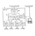
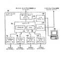
ここで、図1を参照すると、プロセス制御システム10は、インターフェイスモジュール16により、Fieldbusプロセス制御ネットワーク14と、インターネットベースのプロトコルに従うプロセス制御ネットワーク17とに接続されている非インターネットベースのプロトコルに従うプロセス制御ネットワーク12を備えうる。非インターネットベースのプロセス制御ネットワーク12は、複数のフィールドデバイス20〜24および一または複数のユーザインターフェイス26に接続されているホストデバイスまたはホストコントローラ18を備えうる。このシステムでは、ホスト18は、非インターネットベースのプロセス制御ネットワーク12およびその動作が従いうる非インターネットベースのプロトコルの要求に依存して、プロセス制御ネットワーク内のプロセス制御を実行するためにおよび、デバイス20〜24およびユーザインターフェイス26により受信される取引を開始するマスターデバイスとして機能するために用いられうる。デバイス20〜24およびユーザインターフェイス26は、ホスト18に要求データを供給することによりまたは問い合わせにより要求される処置を講ずることにより返答しうる。 Referring now to FIG. 1, the
Fieldbusプロセス制御ネットワーク14は、2線式のFieldbusループまたはFieldbusバスを通じて複数の他のデバイスに接続されているホストまたはコントローラ28を備えうる。複数の他のデバイスには、プログラム論理コントローラ(PLC)30、複数のコントローラ32、他のホストデバイス34およびフィールドデバイスの集合36〜66、が含まれる。Fieldbusプロセス制御ネットワーク14は、さまざまなセクションまたはセグメント68a、68b、68c、68dを有しうる。セグメント68bの如きいくつかのセグメントはバス68に直接接続されても良いし、セグメント68a、68cの如き他のセグメントはブリッジデバイス70、74によりバス68に接続されても良い。さらに、Fieldbusプロセス制御ネットワーク14は、インターフェイスモジュール16によりFieldbusプロセス制御ネットワーク14に接続されているセグメント68dの如きセグメントを有していても良い。セクション68a、68b、68c、68dの各々は、先に記載の方法でデバイス間の通信を可能とするために、上述のデバイスの部分集合を相互接続している。通信を起こすために、バス68の各セグメント上のデバイスのうちの1つは、バス68の対応するセグメント上の通信を積極的にスケジュールし、制御するリンクアクティブスケジューラ(たとえば、コントローラ28、デバイス36、48、56、64)として動作するようになっている。 The Fieldbus process control network 14 may include a host or
非インターネットベースのネットワーク12は、インターフェイスモジュール16により、Fieldbusネットワーク14に接続されている。インターフェイスモジュール16は、非インターネットベースのプロセス制御ネットワーク12とプロトコル互換性を有するように構成されている入力/出力(I/O)ポートを通じて非インターネットベースのネットワーク12に接続され、Fieldbusと互換性を有するI/Oポートを通じてFieldbusネットワーク14のセグメント68a、68b、68c、68dのうちの一または複数のセグメント上のノードに接続されている。非インターネットベースのネットワーク12内においてインターフェイスモジュール16間の通信を促進するために、インターフェイスモジュール16は、ネットワーク12のプロトコル内のデバイスアドレスを割り当てられても良い。さらに、インターフェイスモジュール16は、デバイス18〜26がインターフェイスモジュール16に対するメッセージの書式を設定して送信し、インターフェイスモジュール16が、ネットワーク12の他のデバイス18〜26と同一の方法でネットワーク12のプロトコルを用いてかつプロトコル互換性を有するI/Oポートを通じて、上述のメッセージを受け取り、識別し、処理し、要求された処置を講じ、デバイス18〜26に向けて応答メッセージを送信することができるように構成されても良い。 The non-Internet based
また、インターフェイスモジュール16は、Fieldbusプロセス制御ネットワーク14のリンクマスターデバイスとして構成されても良い。これにより、インターフェイスモジュール16は、当該インターフェイスモジュール16に接続しているFieldbusプロセス制御ネットワーク14のセグメントのうちの一または複数のセグメントに対するリンクアクティブスケジューラとして機能しても良い。さらに、上述のように、インターフェイスモジュール16は、Fieldbusプロセス制御ネットワーク14の、バス68に直接接続されえないセグメント68dの如きセグメントおよび/または他のセグメント68a、68b、68cの間の通信を促進するためのブリッジデバイスとしてさらに機能しても良い。 In addition, the
非インターネットベースのネットワーク12と同様に、インターフェイスモジュール16は、Fieldbus I/Oポートを通じて接続されているバス68のセグメント68a、68b、68c、68d上で通信することができる。インターフェイスモジュール16にはFieldbusデバイスアドレスが割り当てられており、これにより、インターフェイスモジュール16は、当該インターフェイスモジュール16が取り付けられているセグメント68a、68b、68cm、68d上のデバイス36〜66により認識されるようになっている。LASデバイス36、48、56、64内のリンクマスタースケジュールは、リンクマスタースケジュールの非同期期間中に、パストークンメッセージがインターフェイスモジュール16へと送信されるように構成されている。デバイス36〜66およびインターフェイスモジュール16のVCRは、インターフェイスモジュール16が格納するように構成されているプロセス制御パラメータの値を要求するメッセージをインターフェイスモジュール16がフィールドデバイス36〜66へ送信し、要求されたFieldbusプロセス制御パラメータの現在値を含んでいる応答メッセージをフィールドデバイス36〜66がインターフェイスモジュール16に送信しうるように構成されている。 Similar to non-Internet-based
インターネットベースのプロトコルに従うプロセス制御ネットワーク17は、当該プロセス制御ネットワーク17が従うインターネットベースのプロトコルを用いて通信しうる複数のフィールドデバイス78〜82および1以上のユーザインターフェイス84に接続されている1以上のホストデバイスまたはコントローラ76を備えうる。プロセス制御ネットワーク17では、ホストデバイス76およびフィールドデバイス78〜82は、プロセス制御ネットワーク17に関連するインターネットベースのプロトコルを用いて、プロセス制御戦略を実行するように構成されうる。また、インターネットベースのプロセス制御ネットワークは、インターフェイスモジュール16により、非インターネットベースのプロセス制御ネットワーク12および/またはFieldbusプロセス制御ネットワーク14に接続されうる。インターフェイスモジュール16は、インターネット互換性を有する入力/出力(I/O)ポートを通じて、インターネットベースのプロセス制御ネットワーク17に接続されている。このI/Oポートにより、ネットワーク17のデバイス76〜84に以下でさらに詳細に説明する方法でインターフェイスモジュール16と通信させることおよび他のプロセス制御ネットワーク12、14と情報交換させることが可能となる。その他のネットワーク12、14と同様に、インターフェイスモジュール16には、インターフェイスモジュール16およびインターネットベースのネットワーク17へ向かうおよびそこからの通信を促進するために、ネットワーク17のプロトコル内のデバイスアドレスが割り当てられうる。このように構成することにより、インターフェイスモジュール16は、ネットワーク17の他のデバイス76〜84と同様に、ネットワーク17のプロトコルに従ってかつインターネット互換性を有するI/Oポートを通じて、メッセージを受信し、識別し、処理し、要求された処置を講じ、デバイス76〜84へ向けて応答メッセージを送信することができる。 The
インターネットベースのネットワーク17と通信し、インターフェイスモジュール16を設定し、そこでコンパイルされたデータを表示するために、インターフェイスモジュール16は、ウェブサーバのソフトウェアでプログラムされうる。インターフェイスモジュール16の設定は、インターネット互換性を有するI/Oポートを通じて、ユーザインターフェイス86の如き、どのパーソナルコンピュータにおいても利用可能な標準的なウェブブラウザソフトウェアを用いて達成されうる。インターフェイスモジュール16のウェブサーバソフトウェアによりユーザインターフェイス86のウェブブラウザソフトウェアに提供されるウェブページにより、プロセスモニターまたはオペレータにFieldbusネットワーク14のデバイス36〜66のプロセス制御パラメータをインターネットベースおよび非インターネットベースのネットワークで用いられる対応するパラメータにマッピングさせることが可能となる。また、上記のウェブページにより、プロセスモニターおよびオペレータに、接続されているネットワークからのプロセス制御パラメータの現在値を閲覧させることが可能となる。これらのパラメータの現在値は、その他の接続されているネットワークのうちの一または複数の対応するパラメータにマッピングされうるし、また、インターフェイスモジュール16に格納されうる。 In order to communicate with the internet-based
ここで、図2を参照すると、インターフェイスモジュール16は、メモリ92に接続されているコントローラ90と、非インターネットベースのプロトコル互換性を有するI/Oモジュール94と、Fieldbus I/Oモジュール96〜102と、インターネット互換性を有するI/Oモジュール104とを備えうる。コントローラ90は、インテルから市販されている16ビットまたは32ビットの16メガヘルツ(MHZ)80C960SAマイクロコントローラの如き市販のハードウェアにより具象化されても良いし、または、その他の適切なマイクロコントローラにより具象化されても良い。コントローラ90は、バス110を通じて、メモリ108に通信可能に接続されているプロセッサ106を備えうる。コントローラ90のメモリ108は、ランダムアクセスメモリ(RAM)であっても良いし、半導体ROMの如き読み出し専用メモリ(ROM)であっても良いし、または、それらのいかなる適切な組み合わせであっても良い。それに代えてまたはそれに加えて、メモリ108は、電気的消去可能PROM(EEPROM)、1度だけプログラム可能な電気的にプログラム可能な読取り専用メモリ(OTP EPROM)、静的ランダムアクセスメモリ(SRAM)、フラッシュメモリ、または、コントローラ90のプロセッサ106に外部から接続されうる他の適切なメモリ素子のうちのいずれか1つを含んでいても良い。さらに、メモリは、たとえばCD、再書き込み可能CD、DVDなどの如き光学媒体、または、たとえばフロッピー(登録商標)ディスク、ハードドライブ、zipディスクなどの如き磁気媒体のような他のコンピュータ読み取り可能な媒体で具象化されても良い。 Referring now to FIG. 2, the
非インターネットI/Oモジュール94は、たとえば標準的なRJ 45/10/1 00btコネクタの如きイーサネット(登録商標)接続用のポートであるRS485シリアルポートまたは当該技術分野において公知になっている上記の具体的な非インターネットベースのプロトコルに従うネットワークへの接続に適した他のコネクタを用いて、非インターネットベースのプロトコルに従うネットワーク12に、コントローラ90を接続している。上記の非インターネットI/Oモジュール94は、対応する非インターネットベースのプロトコルに従って、ホスト18、フィールドデバイス20〜24およびユーザインターフェイス26と通信するように構成されている。たとえば非インターネットベースのネットワーク12がProfibus DPネットワークである場合、非インターネットI/Oモジュール94は、Profibus DPネットワーク12上で送信されるメッセージを受信し、また、インターフェイスモジュール16に割り当てられたProfibus DPアドレスを含んでいるホスト18または他のマスターデバイスにより送信されるメッセージを検出するように構成されうる。一旦検出すると、非インターネットI/Oモジュール94は、メッセージに含まれているデータを抽出し、必要な場合書式を再設定し、その情報をコントローラ90へ転送して、ホスト18から要求されたサービスを実行しうる。また、非インターネットI/Oモジュール94は、コントローラ90からデータを受信するようにさらに構成されうる。このデータは、ホスト18からのサービス要求に応じて提供されうる。適切なProfibus DPプロトコルに従うメッセージが書式を整えて作成され、このメッセージが、非インターネットI/Oモジュール94を通過して、Profibus DPネットワーク12へ送信される。 The non-Internet I /
当業者にとって明らかなように、非インターネットI/Oモジュール94は、対応するプロトコルに従った、非インターネットベースのネットワーク12のデバイスとインターフェイスモジュール16との間の通信を促進するいかなる適切な方法で実現されても良い。たとえば、非インターネットI/Oモジュール94は、ネットワーク12内で用いられている非インターネットプロトコルに従ってネットワーク12とインターフェイスモジュール16との間の通信を行うようにプログラムされうるインターフェイスモジュール16内のソフトウェアとして実現されても良い。そのような実施形態では、I/Oモジュール94は、外部格納デバイスからプログラムインストラクションをダウンロードすることにより、インターフェイスモジュール16においてプログラムまたは再プログラムされうる。あるいは、I/Oモジュール94は、インターネットを通じてインターフェイスモジュール16に接続さているユーザインターフェイス86からコードをダウンロードすることにより、再プログラムおよび再設定(reconfigure)されても良い。さらに、インターフェイスモジュール16は、当該インターフェイスモジュール16が接続されうるプロセス制御ネットワークにおいて用いられうる複数の非インターネットベースのプロトコル用のソフトウェアで前もってプログラムされていても良い。インターフェイスモジュール16が接続されるプロセス制御ネットワーク12のプロトコルが特定されると、インターフェイスモジュール16は、利用可能なプロトコルのうちの該当する1つのプロトコルのソフトウェアを実行し、非インターネットI/Oモジュール94が適切なプロトコルに従ってプロセス制御ネットワーク12のデバイス18〜26と通信することができるようするように構成されても良い。さらに他の実施形態では、I/Oモジュール94はモジュール式でありうる。したがって、ある非インターネットプロトコル用の物理モジュールをインターフェイスモジュール16から切り離して取り除き、インターフェイスモジュール16が接続されるプロセス制御ネットワーク用の適切なプロトコルに従って通信するように構成されている他の物理モジュールと交換しうる。 As will be apparent to those skilled in the art, the non-Internet I /
非インターネットI/Oモジュール94と同様の方法で、Fieldbus I/Oモジュール96〜102は、たとえばH1I/Oカードを用いて、コントローラ90をFieldbusセグメント68a、68b、68c、68dに接続し、コントローラ90とFieldbusフィールドデバイス36〜66との間の通信を促進する。Fieldbus I/Oモジュール96〜102のうちの一または複数は、対応して、セグメント68a、68b、68c、68dのノードに取り付けられており、また、インターフェイスモジュール16には、セグメント68a、68b、68c、68dに接続されているフィールドデバイス36〜66と通信するために用いられるFieldbusアドレスが割り当てられている。リンクアクティブスケジュールは、インターフェイスモジュール16のためのパストークンメッセージが、スケジュールの非同期通信期間中にLASフィールドデバイス36、48、56、64により送信されるように構成されている。Fieldbus I/Oモジュール96〜102は、インターフェイスモジュール16のためのパストークンメッセージおよびセグメント68a、68b、68c、68d上で送信されているインターフェイスモジュール16のための他のメッセージを検知し、これらのメッセージ内の情報をコントローラ90へ送信し、処理する。インターフェイスモジュール16が、Fieldbusネットワーク14のフィールドデバイス36〜66と通信するとき、コントローラ90は、Fieldbus I/Oモジュール96〜102にFieldbusプロトコルメッセージを書式を合わせて作成し、これらのメッセージを適切なFieldbusセグメント68a、68b、68c、68dに送信させる。 In a manner similar to non-Internet I /
インターネットI/Oモジュール104は、プロセス制御ネットワーク17の如きインターネットベースのプロセス制御ネットワークおよび/またはユーザインターフェイス86へ、インターフェイスモジュール16を接続しうる。インターフェイスモジュール16は、標準的なウェブサーバソフトウェアでプログラムされても良い。こうすることで、ユーザインターフェイス86の如きウェブブラウザを備えたコンピュータは、インターフェイスモジュール16に接続することにより、インターフェイスモジュール16を設定するためおよびそこに格納されているプロセス制御情報を閲覧するために用いられうる。インターネットI/Oモジュール104は、コントローラ90に接続され、たとえば標準的なRJ45/10/100bTコネクタなどの如きイーサネット(登録商標)接続のためのポートを備えうる。あるいは、インターネットI/Oモジュール104は、その他のタイプのインターネット接続に適切なポートを備えていても良いし、インターネットベースのプロセス制御ネットワーク17および/またはユーザインターフェイス86と通信するための無線通信能力を有するようにさらに構成されていても良い。インターフェイスモジュール16の実施形態に応じて、インターネット接続は、インターフェイスモジュール16を直接ユーザインターフェイス86へ接続するためにまたは、これに代えて、ローカルエリアネットワークへ接続するために用いられても良い。このローカルエリアネットワークでは、ウェブブラウザソフトウェアを備え、ネットワーク化されている複数のデバイスに、インターフェイスモジュール16内に格納されている情報へのアクセスが提供される。さらに、ユーザインターフェイス86は、インターネットベースのプロセス制御ネットワーク17内のデバイスであっても良い。非インターネットI/Oモジュール94と同様に、インターフェイスモジュール16は、インターネットI/Oモジュール104に、対応するインターネットベースの通信プロトコルに従ってインターネットプロセス制御ネットワーク17と通信させるようにプログラムされても良いしまたは再プログラムされても良い。 Internet I /
一部の実施形態では、インターフェイスモジュール16は、Fieldbusプロセス制御ネットワーク14からプロセス制御情報を取得して格納し、プロセス制御ネットワーク12、17のデバイスから要求を受信すると、格納されたFieldbusプロセス制御情報をプロセス制御ネットワーク12、17へ送信するように構成されている。プロセス制御ネットワーク12、17内のデバイスにFieldbusネットワーク14内で用いられているプロセス制御パラメータの値を要求させることを可能とするため、Fieldbusネットワーク14内で用いられるプロセス制御パラメータは、プロセス制御ネットワーク12、17内の対応するパラメータまたはデータ構造にマッピングされうる。このとき、Fieldbusプロセス制御パラメータの値は、インターフェイスモジュール16のメモリ108内の一または複数のデータベースに格納される。一旦Fieldbusプロセス制御パラメータがプロセス制御ネットワーク12、17内のデータ構造にマッピングされると、プロセス制御ネットワーク12、17のデバイスは、対応するプロトコルに従うおよびFieldbusプロセス制御パラメータがマッピングされたデータ構造の値を要求するメッセージを、インターフェイスモジュール16へ送信するように構成されうる。インターフェイスモジュール16で要求メッセージを受け取ると、コントローラ90のプロセッサ106は、要求メッセージ内のデータ構造に対応するメモリ108内のデータベースに格納されている値を調べ、対応するI/Oモジュール94、104に、そのデータ構造および対応するFieldbusプロセス制御パラメータの値とともにプロトコル指定メッセージを書式を合わせて作成させ、送信させる。要求側の装置は、対応するプロセス制御ネットワーク12、17のデバイスにより送信される応答メッセージと同じ方法で応答メッセージを受信し、処理する。 In some embodiments, the
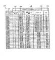
上述のように、Fieldbusプロセス制御パラメータは、インターフェイスモジュール16のメモリ108内に格納されているデータベース内のプロセス制御ネットワーク12、17の対応するデータ構造にマッピングされる。図3には、インターフェイスモジュール16で構築され、コントローラ90のメモリ108に格納されるデータベース120の1例が示されている。このデータベース120は、Fieldbusプロセス制御パラメータをProfibus DPサービスアクセスポイントにマッピングしている。この例では、非インターネットベースのプロセス制御ネットワーク12は、当該技術分野で公知になっているProfibus DPプロセス制御ネットワークでありうる。Profibus DPサービスアクセスポイント122にマッピングされている各Fieldbusプロセス制御パラメータについては、サービスアクセスポイントデータベース120は、Fieldbusプロセス制御パラメータの現在値132に加えて、セグメント識別子124、デバイス識別子126、機能ブロック識別子128およびパラメータ識別子130を含んでいてもよい。図3の具体例には、ホスト18の如きProfibus DPプロセス制御ネットワーク12のマスターデバイスが、Fieldbusプロセス制御ネットワーク14の機能ブロックの一部または全部の出力値および出力ステータスをインターフェイスモジュール16を通じて取得することができうる本発明にかかるインターフェイスモジュール16の一つの実施形態が示されている。図3のサービスアクセスポイントデータベース120では、45,001〜45,999の範囲のサービスアクセスポイントが、さまざまなFieldbus機能ブロックの現在の出力ステータスを格納するためにマッピングされても良く、また、47,001〜47,999の範囲のサービスアクセスポイントが、さまざまなFieldbus機能ブロックの出力値を格納するためにマッピングされても良い。たとえば、図3のデータベース120では、セグメント1上のデバイス848−01の熱変換器TT−01−1の出力ステータスがProfibus DPサービスアクセスポイント45,001にマッピングされても良く、熱変換器TT−01−1の出力値がProfibus DPサービスアクセスポイント47,001にマッピングされても良い。同様に、セグメント3上のデバイス3051−44の圧変換器PP−44−1の出力ステータスがProfibus DPサービスアクセスポイント45,324にマッピングされても良く、圧変換器PP−44−1の出力値がサービスアクセスポイント47,647にマッピングされても良い。一旦Fieldbusプロセス制御パラメータがProfibus DPサービスアクセスポイントにマッピングされると、Profibus DPネットワーク12内のマスターデバイスは、本明細書においてさらに十分に記載する方法で対応するサービスアクセスポイント122を用いて、インターフェイスモジュール16にFieldbusプロセス制御パラメータの現在値を要求しうる。 As described above, the Fieldbus process control parameters are mapped to corresponding data structures of the
本明細書記載のサービスアクセスポイントデータベース100が、機能ブロックの出力値および出力ステータスをProfibus DPサービスアクセスポイントへマッピングするようになっているが、当業者にとって明らかなように、Fieldbusプロセス制御ネットワークのFieldbusデバイスにより用いられるいかなるプロセス制御パラメータがサービスアクセスポイントデータベース内のProfibus DPサービスアクセスポイントにマッピングされても良い。いうまでもなく、Profibus DPサービスアクセスポイントにマッピングされるFieldbusプロセス制御パラメータは、インターフェイスモジュール16が実装されるプロセス制御システムの必要要件によって決められても良い。さらに、Fieldbusプロセス制御ネットワーク14のパラメータは、I/Oモジュール94、104に接続されているプロセス制御ネットワーク12、17の対応するデータ構造にマッピングされても良い。また、インターフェイスモジュール16により接続されているプロセス制御ネットワークを統合するにあたって必要な情報の交換を促進させるために、インターフェイスモジュール16が、プロセス制御ネットワーク12、17のプロセス制御パラメータをFieldbusプロセス制御パラメータにマッピングして良いし、または、非Fieldbusプロセス制御ネットワークのパラメータが、インターフェイスモジュール16に接続されている他の非Fieldbusプロセス制御ネットワークのパラメータにマッピングされても良い。 The service
Profibus DPの例に戻ると、サービスアクセスポイントデータベース120を確立するために、インターフェイスモジュール16は、まずFieldbusネットワーク14のフィールドデバイス36〜66内に存在する機能ブロックおよびプロセス制御パラメータを特定しなければならない。上述のように、一旦インターフェイスモジュール16がFieldbusネットワーク14のセグメント68a、68b、68c、68dのうちの一または複数にFieldbus I/Oモジュール96〜102を通じて接続されると、対応するLASフィールドデバイス36、48、56、64のリンクアクティブスケジュールは、スケジュールの非同期期間中にインターフェイスモジュール16のパストークンメッセージを送信するように構成されている。インターフェイスモジュール16がセグメント68a、68b、68c、68dのうちの1つでパストークンメッセージを受信すると、インターフェイスモジュール16は、対応するフィールドデバイスを、存在の有無、内部に格納している機能ブロックおよび機能ブロックにより用いられるプロセス制御パラメータに関する情報を求めてポーリングするメッセージをセグメント上で送信する。たとえば、インターフェイスモジュール16がセグメント68aに接続され、LASフィールドデバイス36が、インターフェイスモジュール16のFieldbusアドレスへパストークンメッセージを送信すると、Fieldbus I/Oモジュール96は、この許可書メッセージを検出し、インターフェイスモジュール16がセグメント68a上でメッセージを送信しうることをコントローラ90に通知する。コントローラ90は、Fieldbus I/Oモジュール96に、フィールドデバイス36〜42をポーリングしてそこに格納されている機能ブロックおよびプロセス制御パラメータに関する情報を求めるメッセージをセグメント68a上で送信させる。フィールドデバイス36〜42は、要求された情報を含んでいるメッセージをインターフェイスモジュール16へ送信することにより応答する。これらの応答メッセージは、Fieldbus I/Oモジュール96により検出される。I/Oモジュール96は、この情報をコントローラ90へ中継する。コントローラ90のプロセッサ106は、サービスアクセスポイントデータベース120の構築に用いるために、フィールドデバイス36〜42からの情報をメモリ108内に格納させる。もしあるとするならば、インターフェイスモジュール16が取り付けられているセグメント68b、68c、68dのフィールドデバイス44〜66のポーリングは、同様に、コントローラ90により実行される。 Returning to the Profibus DP example, in order to establish the service
一旦Fieldbusネットワーク14のプロセス制御パラメータに関する情報が、インターフェイスモジュール16によりコンパイルされると、プロセス制御パラメータは、ユーザインターフェイス86のウェブブラウザを用いてProfibus DPサービスアクセスポイントにマッピングされうる。メモリ108に格納されている利用可能なプロセス制御パラメータの情報は、ユーザインターフェイス86からサービス要求を受信すると、コントローラ80からインターネットI/Oモジュール104を経てユーザインターフェイス86へ送信されうる。一旦表示されると、コントローラ90のウェブサーバソフトウェアにより提供されるウェブページを用いて、利用可能なプロセス制御パラメータ閲覧し、Profibus DPネットワーク12による使用のため、これらのプロセス制御パラメータをProfibus DPサービスアクセスポイントにマッピングすることが可能となる。サービスアクセスポイントがプロセス制御パラメータに割り当てられるとき、情報がユーザインターフェイス86からインターフェイスモジュール16へ送信されても良いし、また、情報がインターネットI/Oモジュール104で受信されたあと、コントローラ90のプロセッサ106が、サービスアクセスポイントを、対応するプロセス制御パラメータに一致する記入項目別にサービスアクセスポイントデータベース120に格納しても良い。 Once the information regarding the process control parameters of the Fieldbus network 14 is compiled by the
他の実施形態では、Fieldbusプロセス制御パラメータは、ウェブブラウザ以外のソフトウェアを用いてユーザインターフェイス86において、Profibus DPサービスアクセスポイントにマッピングされうる。マッピングは、たとえばMicrosoft(登録商標)エクセル表計算プログラムの如き市販のソフトウェアアプリケーションを用いてまたは特別に注文されたソフトウェアアプリケーションを用いて実行されても良い。ソフトウェアアプリケーションは、ユーザインターフェイス86とインターフェイスモジュール16との間のイーサネット(登録商標)接続を通じて、メモリ108内に格納されている利用可能なプロセス制御パラメータの情報を求める要求を発行しうる。コントローラ90のプロセッサ106は、メモリ108に格納されている要求情報を検索し、検索された情報をユーザインターフェイス86にインターネット接続を通じて送信させることにより、応答しても良い。この情報が、一旦、ユーザインターフェイス86により受信され、ソフトウェアアプリケーションにより表示されると、このソフトウェアアプリケーションは、ユーザに、利用可能なプロセス制御パラメータに関する情報を閲覧させ、これらのプロセス制御パラメータをProfibus DPサービスアクセスポイントにマッピングするための操作を行わせ、Profibus DPネットワーク12により使用を可能とする。ソフトウェアアプリケーションを用いて、サービスアクセスポイントがプロセス制御パラメータに割り当てられるとき、最新の情報がユーザインターフェイス86からインターフェイスモジュール16へ送信されても良いし、また、この情報がインターネットI/Oモジュール104で受信されたあと、コントローラ90のプロセッサ106が、サービスアクセスポイントを、対応するプロセス制御パラメータに一致する記入項目別にサービスアクセスポイントデータベース120に格納しても良い。 In other embodiments, the Fieldbus process control parameters may be mapped to the Profibus DP service access point at the
オペレータが、ユーザインターフェイス86でウェブブラウザを用いて、Profibus DPサービスアクセスポイントをFieldbusプロセス制御パラメータに手動でマッピングすることに加えて、インターフェイスモジュール16は、インターフェイスモジュール16のコントローラ90がフィールドデバイス36〜66におけるプロセス制御変数にサービスアクセスポイントを自動的に割り当てる自動マッピングモードを有しても良い。この自動マッピングは、マッピングされているパラメータのタイプに配慮することなくサービスアクセスポイントを無作為にまたは順次割り当てても良いし、またはこれに代えて、前もって定義されているサービスアクセスポイント範囲が、Fieldbusネットワーク14内で用いられうるさまざまなタイプのパラメータに対して指定されても良い。 In addition to the operator manually mapping the Profibus DP service access point to the Fieldbus process control parameters using a web browser at the
一旦Fieldbusネットワーク14のプロセス制御パラメータが、Profibus DPネットワーク12のサービスアクセスポイントにマッピングされると、ホスト18および他のマスターデバイスは、Fieldbusネットワーク14のプロセス制御パラメータがマッピングされたProfibus DPサービスアクセスポイントの値を求めるサービス要求をインターフェイスモジュール16に対して発行するように構成されている。Profibus DPデバイスの設定は、個々のProfibus DPマスターデバイスにおいてオペレータにより手動で行なわれうる。あるいは、設定プロセスは、コントローラ90のプロセッサ106により非インターネットI/Oモジュール94にFieldbusプロセス制御パラメータにマッピングされたサービスアクセスポイントを格納しているProfibus DPネットワーク12のマスターデバイスに向けてメッセージを送信させることにより、半自動式に実行されても良い。これらのメッセージ内に含まれているデータは、マッッピングされたサービスアクセスポイントに関連する値を検索するようインターフェイスモジュール16に向けてサービス要求メッセージを発行するようにProfibus DPマスターデバイスを設定するために、オペレータにより用いられても良い。 Once the process control parameters of the Fieldbus network 14 are mapped to the service access point of the
Profibus DPマスターデバイスにより発行されるサービス要求メッセージは、インターフェイスモジュール16のDPデバイスアドレス、一または複数のサービスアクセスポイントの値を読み込むようにインターフェイスモジュール16に要求するサービスコードおよびインターフェイスモジュール16により読み込まれるサービスアクセスポイントまたはその数を含んでいる。要求メッセージは、非インターネットI/Oモジュール94で受信される。非インターネットI/Oモジュール94は、要求メッセージを復元し、コントローラ90に要求を伝達する。要求を受信すると、コントローラ90のプロセッサ106は、Profibus DPマスターデバイスにより要求されたサービスアクセスポイントまたはその数に対応するプロセス制御パラメータの値を検索するために、メモリ108に格納されているサービスアクセスポイントデータベース120を読み込む。一旦値が検索されたならば、プロセッサ106は、非インターネットI/Oモジュール94に、サービスアクセスポイントデータベース120に格納されている値を含むProfibus DP応答メッセージを形式を合わせて作成させ、要求元のマスターデバイスに向けて送信させる。 The service request message issued by the Profibus DP master device includes the DP device address of the
サービスアクセスポイントデータベース120がFieldbusプロセス制御パラメータの現在値をその内部に格納して有していることを担保するために、コントローラ90のプロセッサ106は、Fieldbus I/Oモジュール96〜102にフィールドデバイス36〜66に向けてFieldbus要求メッセージを送信させても良い。対応するセグメント68a、68b、68c、68d上でパストークンメッセージを受信すると、Fieldbus I/Oモジュール96〜102は、少なくとも1つのプロセス制御パラメータがProfibus DPサービスアクセスポイントにマッピングされたフィールドデバイス36〜66の各々に向けてメッセージを送信しうる。これらのメッセージは、パストークンメッセージの受信毎に送信されても良いし、または、プロセス制御パラメータもしくはフィールドデバイスのタイプに依存してもしくはFieldbusネットワーク14のメッセージ送信量制限に依存して低い頻度で送信されても良い。あるいは、Profibus DPサービスアクセスポイントの現在値を求める要求をProfibus DPマスターデバイスから受信すると、コントローラ90は、Fieldbus I/Oモジュール96〜102の対応する1つに、プロセス制御パラメータの現在値を求める要求をフィールドデバイス36〜66の適切な1つに向けて送信させるように構成されても良い。一旦フィールドデバイス36〜66の1つが要求されたプロセス制御パラメータ値に対して応答すると、プロセッサ106は、新しい値でサービスアクセスポイントデータベース120を更新し、非インターネットI/Oモジュール94に、要求元のProfibus DPマスターデバイスへ向けて適切な応答メッセージを送信させうる。 In order to ensure that the service
先の場合と同様に、FieldbusからProfibusDPへのマッピングは例示の意味を意図している。インターフェイスモジュール16は、インターフェイスモジュール16がProfibus DPデバイスからのサービスアクセスポイントの値を格納し、Fieldbusデバイスからの要求に応答して、それらの値を送信しうるように、Profibus DPネットワーク12のサービスアクセスポイントをFieldbusネットワーク14のFieldbusパラメータへマッピングするようにさらに構成されうる。他の例として、ModBus TCPネットワークは、インターフェイスモジュール16のインターネットI/Oモジュール104に接続されても良い。Fieldbusネットワークのパラメータは、ModBus TCPデータ構造にマッピングされ、また、ModBus TCPデータ構造は、Fieldbusネットワークのパラメータにマッピングされ、所望ならば、ModBus TCPネットワークのデータ構造は、非インターネットI/Oモジュール94に接続されている非インターネットネットワークまたはインターネットI/Oモジュール104に接続された他のインターネットベースのネットワークのデータ構造にマッピングされる。さらに、インターフェイスモジュール16には、所望の数のプロセス制御ネットワーク12、14、17の接続および統合を容易にするために、さらなるI/Oモジュール84〜104が組み込まれても良い。 As before, the mapping from Fieldbus to ProfibusDP is intended to be exemplary. The
インターフェイスモジュール16より接続されているプロセス制御ネットワーク間の接続が実質的に絶え間のないものであることを担保するために、インターフェイスモジュール16およびそれにより提供される接続には、接続されているプロセス制御ネットワーク内に構築される冗長メカニズムに加えて冗長システムが組み込まれても良い。1つの実施形態では、各インターフェイスモジュール16がメッセージを受信し、プロセス制御ネットワーク上で返答することができうるように、複数のインターフェイスモジュール16が、同一の構成内で、2つ以上のプロセス制御ネットワーク間に接続されうる。さらに、インターフェイスモジュール16は、各インターフェイスモジュール16が上述のような方法でユーザインターフェイス86により設定されうるように、ユーザインターフェイス86に接続されうる。ユーザインターフェイス86は、各インターフェイスモジュール16がプロセス制御ネットワーク間で情報を伝達すべく動作体制が整えられるように、各インターフェイスモジュール16を設定するように構成されうる。動作においては、インターフェイスモジュール16のうちの1つが、ある与えられた時間において、プロセス制御ネットワークのフィールドデバイスからの要求に応答するためにアクティブな状態でありうるし、その一方で、残りのインターフェイスモジュール16がスタンバイモードにセットされうる。このスタンバイモードでは、インターフェイスモジュール16が、フィールドデバイスから情報を取得し、動作中のインターフェイスモジュール16と同期したまま留まるためにデータベース内に格納された情報を更新しうる。インターフェイスモジュール16のモード管理は、接続されているプロセス制御ネットワーク間においてアクティブな接続を維持すべくインターフェイスモジュール16のステータスを監視し、インターフェイスモジュール16のステータスの変化に基づいて、インターフェイスモジュール16の動作モード、たとえばアクティブモードまたはスタンドバイモードを手動でまたは自動的に調節するように、インターフェイスモジュール16間の接続を通じて、ユーザインターフェイス86を通じてまたはインターフェイスモジュール16間の他の共通の接続を通じて行われても良い。 In order to ensure that the connection between the process control networks connected by the
さらに他の実施形態では、ある与えられたプロセス制御ネットワークに対するインターフェイスモジュール16の常時接続が維持されるように、冗長性が、複数のI/Oモジュール94、104提供することによりまたはI/Oモジュール94、104に複数の入力ポート提供することにより、インターフェイスモジュール16自体に組み込まれても良い。図4には、第二のインターネットI/Oモジュール140がインターフェイスモジュール16に冗長性を少なくとも部分的に提供するために提供されているインターフェイスモジュール16のある実施形態が例示されている。インターネットI/Oモジュール140は、インターネットI/Oモジュール104と同等であっても良いし、また、コントローラ90に接続されていても良い。また、インターネットI/Oモジュール140は、インターネットベースのプロセス制御ネットワーク17および/またはユーザインターフェイス86にI/Oモジュール140を接続するための通信ポートまたは無線通信機能を備えている。図示されている実施形態では、インターネットI/Oモジュール104、140は、インターフェイスモジュール16、プロセス制御ネットワーク17およびユーザインターフェイス86の間の通信を促進するために、インターネットベースのプロセス制御ネットワーク17に接続されうる。ある与えられた時間では、インターネットI/Oモジュール104、140のうちの1つは、インターネットプロセス制御ネットワーク17およびユーザインターフェイス86との通信のためのアクティブモジュールとしてコントローラ90により指定されうるし、その他のインターネットI/Oモジュール104、140は、ソフトウェア故障またはプロセス制御ネットワーク17への接続の切断の場合の如きアクティブなモジュールを通じた通信が切断された場合において利用可能なスタンバイモジュールとしてコントローラ90により指定されうる。コントローラ90は、そのような通信混乱を修復するために、通信混乱を検出し、スタンバイモジュールをプロセス制御ネットワーク17との通信のためにアクティブな状態に置き、アクティブなモジュールをサービス不能状態にするように構成されうる。さらに、コントローラ90は、インターフェイスモジュール16の状態をシステムオペレータに通知するための、接続されているプロセス制御ネットワーク12、14、17のうちの1つの中の適切なデバイスに向けて、動作不能状態にされたI/Oモジュール104、140のステータスに関するメッセージを送信しうる。本明細書において例示および記述されている冗長性はインターネットI/Oモジュール104、140に関連するものであるが、当業者にとって明らかなように、同様の冗長戦略が、接続されているプロセス制御ネットワーク12,14,17と常時通信リンクを担保するために、インターフェイスモジュール16のI/Oモジュールのうちのいずれに対して実施されても良い。 In still other embodiments, redundancy is provided by providing a plurality of I /
以上において本発明の複数の異なる実施形態が詳細に記載されているが、いうまでもなく、本発明の法的範疇は、本明細書の終わりに記載されている特許請求の範囲の文言により定義される。詳細な説明は、例示としてのみ解釈されるべきであり、本発明のあらゆる可能な実施形態を記載したものではない。というのは、すべての可能な実施形態を記載することは、不可能なことではないとしても非現実的なことであるためである。現在の技術を用いまたは本明細書の出願日以降に開発される技術を用いて多くの他の実施形態が実施された場合であっても、それらもまた、本発明を定義する特許請求の範囲に含まれるものとする。 While several different embodiments of the invention have been described in detail above, it will be appreciated that the legal scope of the invention is defined by the language of the claims set forth at the end of the specification. Is done. The detailed description is to be construed as illustrative only and does not describe every possible embodiment of the invention. This is because it is impractical, if not impossible, to describe all possible embodiments. Even when many other embodiments are implemented using current technology or using technology developed after the filing date of this specification, they are also claimed as defining the invention. Shall be included.
Claims (42)
Translated fromJapanese前記プロセス制御設備内の複数の非Fieldbusプロセス制御ネットワークからなる第一の非Fieldbusプロセス制御ネットワークへ作用可能に接続され、該第一の非Fieldbusプロセス制御ネットワーク上でメッセージの送受信を行うように構成されている第一の非FieldbusI/Oモジュールと、
前記プロセス制御設備内の複数の非Fieldbusプロセス制御ネットワークからなる第二の非Fieldbusプロセス制御ネットワークへ作用可能に接続され、該第二の非Fieldbusプロセス制御ネットワーク上でメッセージの送受信を行うように構成されている第二の非FieldbusI/Oモジュールと、
前記プロセス制御設備内において、前記Fieldbusプロセス制御ネットワークへ作用可能に接続され、前記Fieldbusプロセス制御ネットワーク上でFieldbusプロトコルメッセージを送受信するように構成され、このFieldbusプロセス制御ネットワーク部分が、第1の非Fieldbusプロセス制御ネットワークの一部から、あるいは第2の非Fieldbusプロセス制御ネットワークの一部から転換されたものである、Fieldbus I/Oモジュールと、
前記FieldbusI/Oモジュールおよび前記第一の非FieldbusI/Oモジュール、および第二の非FieldbusI/Oモジュールへ作用可能に接続されているとともに、プロセッサおよび該プロセッサに作用可能に接続されているメモリを有しているコントローラと、を備えており、
前記コントローラは、Fieldbusプロセス制御ネットワークの少なくとも1つのFieldbusプロセス制御パラメータに関する情報を含むテーブルを、前記メモリに格納するようにプログラムされており、
この少なくとも1つのFieldbusプロセス制御パラメータに関する情報には、
第一の非Fieldbusプロセス制御ネットワークについての第一の非Fieldbusプロセス制御パラメータの第一の識別子と対応づけられる、少なくとも1つのFieldbusプロセス制御パラメータに関する第一のマッピングと、
第二の非Fieldbusプロセス制御ネットワークについての第二の非Fieldbusプロセス制御パラメータの第二の識別子と対応づけられる、少なくとも1つのFieldbusプロセス制御パラメータに関する第二のマッピングと、が含まれており、
前記コントローラが、前記Fieldbus I/Oモジュールに、前記少なくとも1つのFieldbusプロセス制御パラメータの現在値を、対応する前記Fieldbusフィールドデバイスに対して要求させるようにプログラムされており、
前記コントローラが、前記テーブル内に、前記少なくとも1つのFieldbusプロセス制御パラメータの現在値を、格納するようにプログラムされており、さらに
前記コントローラが、第一の非Fieldbusプロセス制御ネットワークの非Fieldbusフィールドデバイスのうちの1つから、第一の非Fieldbusプロセス制御パラメータの現在値を求める第一の要求メッセージを第一の非Fieldbus I/Oモジュールで受信することに応答して、前記第一の非Fieldbus I/Oモジュールに、前記第一の非Fieldbusプロセス制御ネットワークの前記非Fieldbusフィールドデバイスのうちの1つに向けて、前記少なくとも1つのFieldbusプロセス制御パラメータの現在値、およびテーブルに格納した第一の非Fieldbusプロセス制御パラメータの第一の識別子と一緒に第一の応答メッセージを送信させるようにプログラムされており、さらにまた、
前記コントローラが、第二の非Fieldbusプロセス制御ネットワークの非Fieldbusフィールドデバイスのうちの1つから、第二の非Fieldbusプロセス制御パラメータの現在値を求める第二の要求メッセージを、第二の非Fieldbus I/Oモジュールで受信することに応答して、前記第二の非FieldbusI/Oモジュールに、前記第二の非Fieldbusプロセス制御ネットワークの前記非Fieldbusフィールドデバイスのうちの1つに向けて、前記Fieldbusプロセス制御パラメータのうちの少なくとも1つの現在値、およびテーブルに格納した第二の非Fieldbusプロセス制御パラメータの第二の識別子と一緒に第二の応答メッセージを送信させるようにプログラムされている、インターフェイスモジュール。This process is used in a process controlfacility comprising a Fieldbus process control network having a plurality of Fieldbus field devices and a plurality of non-Fieldbus process control networks each having a plurality of non-Fieldbus field devices. the Fieldbus process control networkin the control equipment, the plurality of non-Fieldbus process and operatively connected to the control network, the Fieldbus process control network and the plurality of non-Fieldbus process control networkin a process control equipmentfor the process control equipment An interface module configured to facilitate the exchange of process control information with
Operatively connected to a first non-Fieldbus process control network comprisinga plurality of non-Fieldbus process control networksin the process control facility , configured to send and receive messages on the first non-Fieldbus process control network A first non-Fieldbus I / O module,
Operatively connected to a second non-Fieldbus process control networkcomprised of a plurality of non-Fieldbus process control networksin the process control facility and configured to send and receive messages on the second non-Fieldbus process control network A second non-Fieldbus I / O module,
Within the process control facility, operatively connected to the Fieldbus process control network and configured to send and receive Fieldbus protocol messages over the Fieldbus process control network, the Fieldbus process control network portion comprising a first non-Fieldbus Fieldbus I / O modules that are converted from part of the process control network or from part of the second non-Fieldbus process control network;
A processor and a memory operably connected to the fieldbus I / O module and the first non-Fieldbus I / O module and the second non-Fieldbus I / O module; And a controller having
The controller is programmed to store in the memory a table containing information about at least one Fieldbus process control parameter of the Fieldbus process control network;
Information regarding this at least one Fieldbus process control parameter includes:
A first mapping for at least one Fieldbus process control parameter associated with a first identifier of the first non-Fieldbus process control parameter for the first non-Fieldbus process control network;
A second mapping for at least one Fieldbus process control parameter associated with a second identifier of the second non-Fieldbus process control parameter for the second non-Fieldbus process control network;
The controller is programmed to cause the Fieldbus I / O module to request the current value of the at least one Fieldbus process control parameter from the corresponding Fieldbus field device;
The controller is programmed to store a current value of the at least one Fieldbus process control parameter in the table, and wherein the controller is configured for a non-Fieldbus field device of a first non-Fieldbus process control network. In response to receiving a first request message from one of the first non-Fieldbus process control parameters for the first non-Fieldbus I / O module, the first non-Fieldbus I / O module. / O module, to one of the non-Fieldbus field devices of the first non-Fieldbus process control network, the current value of the at least one Fieldbus process control parameter, and a With the first first identifier of the non-Fieldbus process control parameters stored in the table and the first response message is programmed to transmit, furthermore,
The controller sends a second request message for a current value of a second non-Fieldbus process control parameter from one of the non-Fieldbus field devices of the second non-Fieldbus process control network to a second non-Fieldbus I In response to receiving at the / O module, the Fieldbus process is directed to the second non-Fieldbus I / O module towards one of the non-Fieldbus field devices of the second non-Fieldbus process control network. Programmed to cause a second response message to be sent along with a current value of at least one of the control parameters and a second identifier of a second non-Fieldbus process control parameter stored in the table; Interface module.
所定期間の時間経過後で、前記FieldbusI/Oモジュールが少なくとも1つのFieldbusプロセス制御パラメータの現在値に対する先の要求を発行した後に、FieldbusI/Oモジュールに、少なくとも1つのFieldbusプロセス制御パラメータの現在値を、対応するFieldbusフィールドデバイスに対して要求させるうちのいずれか1つを実行させるようにプログラムされてなる、請求項1記載のインターフェイスモジュール。Each time the controller receives a pass token message from the Fieldbus process control network at the Fieldbus I / O module, the Fieldbus I / O module uses the non-scheduled standby communication to the at least one of the at least one. The current value of one Fieldbus process control parameter is requested to the corresponding Fieldbus field device, or after a predetermined period of time has elapsed, the Fieldbus I / O module has a previous value for the current value of at least one Fieldbus process control parameter. After issuing the request, the Fieldbus I / O module is given the current value of at least one Fieldbus process control parameter in the corresponding Fieldbus field. Formed by programmed to perform any one to be required for field device of claim 1, wherein the interface module.
前記インターフェイスモジュールは、各々が前記コントローラと前記Fieldbusプロセス制御ネットワークの前記セグメントのうちの1つに作用可能に接続されている複数のFieldbus I/Oモジュールを備えており、
各Fieldbus I/Oモジュールが、前記セグメントのうちの対応する1つのセグメント上でFieldbusプロトコルメッセージを送受信するように構成されており、
前記コントローラは、対応する前記Fieldbusフィールドデバイスが作用可能に接続されている前記セグメントのうちの一つのセグメントに作用可能に接続されている前記FieldbusI/Oモジュールのうちの1つに、前記少なくとも1つのFieldbusプロセス制御パラメータの現在値を要求させるようにプログラムされてなる、請求項1記載のインターフェイスモジュール。The Fieldbus process control network comprises a plurality of segments each having at least one Fieldbus field device operably connected;
The interface module comprises a plurality of Fieldbus I / O modules each operatively connected to the controller and one of the segments of the Fieldbus process control network;
Each Fieldbus I / O module is configured to send and receive Fieldbus protocol messages on a corresponding one of the segments;
The controller may include the at least one of the Fieldbus I / O modules operatively connected to one of the segments to which the corresponding Fieldbus field device is operatively connected. The interface module of claim 1, wherein the interface module is programmed to request a current value of a Fieldbus process control parameter.
インターネットベースの通信プロトコルを用いて通信を行う複数の第一の非Fieldbusフィールドデバイスを有している、前記プロセス制御設備内の第一の非Fieldbusプロセス制御ネットワークと、
非インターネットベースの通信プロトコルを用いて通信を行う複数の第二の非Fieldbusフィールドデバイスを有している、前記プロセス制御設備内の第二の非Fieldbusプロセス制御ネットワークと、
複数のFieldbusフィールドデバイスを有している、前記プロセス制御設備内のFieldbusプロセス制御ネットワークであり、該Fieldbusプロセス制御ネットワークは、第1の非Fieldbusプロセス制御ネットワークの一部から、あるいは第2の非Fieldbusプロセス制御ネットワークの一部から転換された部分を含むプロセス制御ネットワークと、
前記プロセス制御設備内において、前記Fieldbusプロセス制御ネットワーク、前記第一の非Fieldbusプロセス制御ネットワーク、および前記第二の非Fieldbusプロセス制御ネットワークそれぞれを作用可能に接続し、前記Fieldbusプロセス制御ネットワーク、前記第一の非Fieldbusプロセス制御ネットワークおよび前記第二の非Fieldbusプロセス制御ネットワークそれぞれの間におけるプロセス制御情報の交換を促進するように構成されている、前記プロセス制御設備内のインターフェイスモジュールとを備えており、
該インターフェイスモジュールが、
前記Fieldbusプロセス制御ネットワークへ作用可能に接続され、前記Fieldbusプロセス制御ネットワーク上でFieldbusプロトコルメッセージを送受信するように構成されているFieldbus I/Oモジュールと、
前記第一の非Fieldbusプロセス制御ネットワークへ作用可能に接続され、前記第一の非Fieldbusプロセス制御ネットワーク上でメッセージを送受信するように構成されている第一の非Fieldbus I/Oモジュールと、
前記第二の非Fieldbusプロセス制御ネットワークへ作用可能に接続され、前記第二の非Fieldbusプロセス制御ネットワーク上でメッセージを送受信するように構成されている第二の非Fieldbus I/Oモジュールと、
前記Fieldbus I/Oモジュール、前記第一の非Fieldbus I/Oモジュール、および前記第二の非Fieldbus I/Oモジュールへ作用可能に接続されているとともに、プロセッサおよび該プロセッサに作用可能に接続されているメモリを有しているコントローラとを備えており、
前記コントローラは、前記Fieldbusプロセス制御ネットワークの少なくとも1つのFieldbusプロセス制御パラメータに関する情報を含むテーブルを前記メモリに格納するようにプログラムされており、この少なくとも1つのFieldbusプロセス制御パラメータに関する情報は、第一の非Fieldbusプロセス制御ネットワークの第一の非Fieldbusプロセス制御パラメータの第一の識別子と、第二の非Fieldbusプロセス制御ネットワークの第二の非Fieldbusプロセス制御パラメータの第二の識別子と対応づけられる、少なくとも1つのFieldbusプロセス制御パラメータに関するマッピングを含んでおり、
前記コントローラが、前記FieldbusI/Oモジュールに、前記Fieldbusプロセス制御ネットワークの、対応する前記Fieldbusフィールドデバイスに対して、前記少なくとも1つのFieldbusプロセス制御パラメータの現在値を要求させるようにプログラムされており、
前記コントローラが、前記テーブル内に、前記少なくとも1つのFieldbusプロセス制御パラメータの現在値を、第一の識別子および第二の識別子と一緒に格納するようにプログラムされており、
前記コントローラが、第一の非Fieldbusプロセス制御ネットワークまたは第二の非Fieldbusプロセス制御ネットワークの非Fieldbusフィールドデバイスのうちの1つから、少なくとも1つのFieldbusプロセス制御パラメータと対応する非Fieldbusプロセス制御パラメータの現在値を求める要求メッセージを、第一の非Fieldbus I/Oモジュールまたは第二の非Fieldbus I/Oモジュールで受信することに応答して、前記第一の非Fieldbus I/Oモジュールまたは前記第二の非Fieldbus I/Oモジュールに、前記第一の非Fieldbusプロセス制御ネットワークまたは第二の非Fieldbusプロセス制御ネットワークの前記非Fieldbusフィールドデバイスのうちの1つに向けて、前記少なくとも1つのFieldbusプロセス制御パラメータの現在値とテーブルに格納されている各識別子と一緒に応答メッセージを送信させるようにプログラムされてなる、プロセス制御設備。Process controlequipment,
And a plurality of first non-Fieldbus field devices that communicate using theInternet-based communicationprotocol, the first non-Fieldbus process control networkof the process control equipment,
A second non-Fieldbus process control networkin the process control facility comprising a plurality of second non-Fieldbus field devices that communicate using a non-Internet based communication protocol;
A Fieldbus process control network in the process control facility having a plurality of Fieldbus field devices, the Fieldbus process control network being from a portion of a first non-Fieldbus process control network or a second non-Fieldbus A process control network including a part converted from a part of the process control network; and
Within the process control facility, the Fieldbus process control network, the first non-Fieldbus process control network, and the second non-Fieldbus process control network are operatively connected to each other,and the Fieldbus process control network, the first An interface modulein the process control facility configured to facilitate the exchange of process control information betweeneach of the non-Fieldbus process control network and the second non-Fieldbus process control network,
The interface module is
A Fieldbus I / O module operably connected to the Fieldbus process control network and configured to send and receive Fieldbus protocol messages on the Fieldbus process control network;
A first non-Fieldbus I / O module operatively connected to the first non-Fieldbus process control network and configured to send and receive messages on the first non-Fieldbus process control network;
A second non-Fieldbus I / O module operatively connected to the second non-Fieldbus process control network and configured to send and receive messages on the second non-Fieldbus process control network;
Operatively connected to the Fieldbus I / O module, the first non-Fieldbus I / O module, and the second non-Fieldbus I / O module and operably connected to the processor and the processor And a controller having a memory,
The controller is programmed to store in the memory a table that includes information about at least one Fieldbus process control parameter of the Fieldbus process control network, the information about the at least one Fieldbus process control parameter being a first At least one associated with a first identifier of a first non-Fieldbus process control parameter of a non-Fieldbus process control network and a second identifier of a second non-Fieldbus process control parameter of a second non-Fieldbus process control network Contains mappings for two Fieldbus process control parameters;
The controller is programmed to cause the Fieldbus I / O module to request the current value of the at least one Fieldbus process control parameter from the corresponding Fieldbus field device of the Fieldbus process control network;
The controller is programmed to store in the table a current value of the at least one Fieldbus process control parameter along with a first identifier and a second identifier;
A current non-Fieldbus process control parameter corresponding to at least one Fieldbus process control parameter from one of the non-Fieldbus field devices of the first non-Fieldbus process control network or the second non-Fieldbus process control network; In response to receiving a request message for a value at the first non-Fieldbus I / O module or the second non-Fieldbus I / O module, the first non-Fieldbus I / O module or the second non-Fieldbus I / O module The non-Fieldbus I / O module includes the non-Fieldbus field of the first non-Fieldbus process control network or the second non-Fieldbus process control network. A process controlfacility programmed to cause a response message to be sent to one of the remote devices along with the current value of the at least one Fieldbus process control parameter and each identifier stored in the table.
要求メッセージの受信に応答して、前記Fieldbus I/Oモジュールに、前記少なくとも1つのFieldbusプロセス制御パラメータの現在値を、対応する前記Fieldbusフィールドデバイスに対して要求させるうちのいずれか一つを実行するようにプログラムされてなる、請求項5記載のプロセス制御設備。The Fieldbus I / O module has the at least one Fieldbus process after a predetermined period has elapsed since the controller of the interface module has issued a previous request for the current value of the at least one Fieldbus process control parameter. Request the current value of the control parameter from the corresponding Fieldbus field device, or
In response to receiving a request message, execute any one of causing the Fieldbus I / O module to request the current value of the at least one Fieldbus process control parameter from the corresponding Fieldbus field device. The process controlfacility of claim 5, programmed as follows.
前記インターフェイスモジュールが、前記コントローラに作用可能に接続されている第三の非Fieldbus I/Oモジュールをさらに備えており、インターネットプロトコルメッセージを前記ユーザインターフェイスに向けて送信し、インターネットプロトコルメッセージを前記ユーザインターフェイスから受信するように構成されてなる、請求項5記載のプロセス制御設備。In addition, it has a user interface,
The interface module further comprises a third non-Fieldbus I / O module operatively connected to the controller, and transmits an internet protocol message to the user interface, and sends an internet protocol message to the user interface The process controlfacility according to claim 5, wherein the process controlfacility is configured to receive from thesystem .
前記Fieldbusプロセス制御ネットワーク上でFieldbusプロトコルメッセージを送受信し、前記複数の非Fieldbusプロセス制御ネットワークを構成する各非Fieldbusプロセス制御ネットワーク上で非Fieldbusプロトコルメッセージを送受信するように構成されている、前記プロセス制御設備内のインターフェイスモジュールを、前記プロセス制御設備内の前記Fieldbusプロセス制御ネットワーク、および、前記プロセス制御設備内の前記複数の非Fieldbusプロセス制御ネットワークへ作用可能に接続するステップであって、前記プロセス制御設備内のFieldbusプロセス制御ネットワーク部分は、前記プロセス制御設備内において、複数の非Fieldbusプロセス制御ネットワークのうちの、少なくとも1つの、非Fieldbusプロセス制御ネットワークの一部から転換されているステップと、
前記Fieldbusプロセスネットワークの少なくとも1つのFieldbusプロセス制御パラメータに関する情報を含むテーブルを、前記インターフェイスモジュールに対応するメモリに格納するステップであって、このFieldbusプロセス制御パラメータの少なくとも1つに関する情報は、第一の非Fieldbusプロセス制御ネットワークの第一の非Fieldbusプロセス制御パラメータの第一の識別子、および第二の非Fieldbusプロセス制御ネットワークの第二の非Fieldbusプロセス制御パラメータの第二の識別子それぞれに対する、少なくとも1つのFieldbusプロセス制御パラメータのマッピングを含んでおり、前記第一の非Fieldbusプロセス制御ネットワークは、インターネットベースのプロトコルを用いて通信を行う複数の非Fieldbusデバイスを含み、前記第二の非Fieldbusプロセス制御ネットワークは、非インターネットベースのプロトコルを用いて通信を行う、異なる、複数の非Fieldbusデバイスを含むステップと、
前記インターフェイスモジュールに、Fieldbusプロセス制御ネットワークにおける、対応するFieldbusフィールドデバイスからの前記少なくとも1つのFieldbusプロセス制御パラメータの現在値を要求させるステップと、
前記少なくとも1つのFieldbusプロセス制御パラメータの現在値を、前記第一の識別子および第二の識別子と一緒に、テーブルに格納するステップと、
第一の非Fieldbusプロセス制御ネットワークまたは第二の非Fieldbusプロセス制御ネットワークのうちのいずれか一方から、第一の非Fieldbusプロセス制御ネットワークまたは第二の非Fieldbusプロセス制御ネットワークのプロセス制御パラメータに関する、少なくとも1つのFieldbusプロセス制御パラメータに対応する現在値を求める要求メッセージを、前記インターフェイスモジュールにおいて受信することに応答して、前記インターフェイスモジュールに、第一の非Fieldbusプロセス制御ネットワークまたは第二の非Fieldbusプロセス制御ネットワークのいずれか一方に向けて、前記少なくとも1つのFieldbusプロセス制御パラメータの現在値と、テーブルに格納された各識別子と一緒に応答メッセージを送信させるステップとを含む、方法。A Fieldbus process control networkin the process control facility having a plurality of Fieldbus field devices; and a plurality of non-Fieldbus process control networksin the process control facility each having a plurality of non-Fieldbus field devices; A method for exchanging process control information between:
The send and receive Fieldbus protocol messages on the Fieldbus process control network is configured to send and receive non-Fieldbus protocol messages on the non-Fieldbus process control network constituting a plurality of non-Fieldbus process control network,the process control Operatively connecting an interface module in thefacility to the Fieldbus process control network inthe process control facility and to the plurality of non-Fieldbus process control networks in theprocess control facility, the process control facility The Fieldbus process control network portion in the process control facility includes a plurality of non-Fieldbus process control networks. Of network, thesteps that have been converted from a portion of at least one, non-Fieldbus process control network,
Storing a table containing information about at least one Fieldbus process control parameter of the Fieldbus process network in a memory corresponding to the interface module, wherein the information about at least one of the Fieldbus process control parameters is a first At least one Fieldbus for each of the first identifier of the first non-Fieldbus process control parameter of the non-Fieldbus process control network and the second identifier of the second non-Fieldbus process control parameter of the second non-Fieldbus process control network. Including a mapping of process control parameters, wherein the first non-Fieldbus process control network includes an Internet A second non-Fieldbus process control network including different, non-Fieldbus devices that communicate using a non-Internet-based protocol, the second non-Fieldbus process control network comprising: When,
Causing the interface module to request a current value of the at least one Fieldbus process control parameter from a corresponding Fieldbus field device in a Fieldbus process control network;
Storing a current value of the at least one Fieldbus process control parameter together with the first and second identifiers in a table;
At least one for process control parameters of the first non-Fieldbus process control network or the second non-Fieldbus process control network from either the first non-Fieldbus process control network or the second non-Fieldbus process control network. Responsive to receiving a request message at the interface module for a current value corresponding to two Fieldbus process control parameters, the interface module may receive a first non-Fieldbus process control network or a second non-Fieldbus process control network. The current value of the at least one Fieldbus process control parameter and the value stored in the table And a step of transmitting a response message with each identifier, method.
所定期間の時間経過後で、前記インターフェイスモジュールが少なくとも1つのFieldbusプロセス制御パラメータの現在値に対する先の要求を発行した後に、前記インターフェイスモジュールに、前記少なくとも1つのFieldbusプロセス制御パラメータの現在値を、対応する前記Fieldbusフィールドデバイスに対して要求させるステップ、あるいは
前記第一の非Fieldbusプロセス制御ネットワークまたは第二の非Fieldbusプロセス制御ネットワークのいずれか一方から、要求メッセージを、インターフェイスモジュールで受信することに応答して、前記インターフェイスモジュールに、前記少なくとも1つのFieldbusプロセス制御パラメータの現在値を、対応する前記Fieldbusフィールドデバイスに対して要求させるステップのうちのいずれか1つをさらに含む請求項12に記載の方法。Each time a pass token message is received at the interface module from the Fieldbus process control network, the interface module is used to provide a current value of the at least one Fieldbus process control parameter using a non-scheduled standby communication. Requesting the corresponding Fieldbus field device,
Corresponding to the interface module the current value of the at least one Fieldbus process control parameter after the interface module has issued a previous request for the current value of the at least one Fieldbus process control parameter after a predetermined period of time has elapsed. response step is required for the Fieldbus field devices or from one ofpre-Symbol first non Fieldbus process control network or thesecond non-Fieldbus process control network, the request message, the receiving interface module The interface module is then provided with a current value of the at least one Fieldbus process control parameter corresponding to the Fieldbus file. 13. The method of claim 12, further comprising any one of the steps of requesting a field device.
前記インターフェイスモジュールで前記ユーザインターフェイスからの第二の要求メッセージを受信することに応答して、前記インターフェイスモジュールに、前記少なくとも1つのFieldbusプロセス制御パラメータに関する情報を前記ユーザインターフェイスに向けて送信させるステップをさらに有する、請求項14記載の方法。The request message is a first request message;
Responsive to receiving a second request message from the user interface at the interface module, further causing the interface module to send information about the at least one Fieldbus process control parameter toward the user interface. 15. The method of claim 14, comprising:
少なくとも一つの第一の非Fieldbusプロセス制御パラメータまたは第二の非Fieldbusプロセス制御パラメータを求める、前記ユーザインターフェイスからの第二の要求メッセージを前記インターフェイスモジュールで受信することに応答して、前記インターフェイスモジュールに、前記少なくとも1つのFieldbusプロセス制御パラメータの現在値、前記少なくとも1つのFieldbusプロセス制御パラメータに関連する情報、および少なくとも1つの第一の識別子または第二の識別子を含む応答メッセージを前記ユーザインターフェイスに向けて送信させるステップをさらに有する、請求項14記載の方法。The request message is a first request message, and the response message is a first response message,
In response to receiving at the interface module a second request message from the user interface for determining at least one first non-Fieldbus process control parameter or a second non-Fieldbus process control parameter. A response message including a current value of the at least one Fieldbus process control parameter, information related to the at least one Fieldbus process control parameter, and at least one first identifier or second identifier to the user interface 15. The method of claim 14, further comprising the step of transmitting.
各々が、プロセス制御設備内における少なくとも一つの非Fieldbusプロセス制御ネットワークへ作用可能に接続され、この少なくとも一つの非Fieldbusプロセス制御ネットワーク上でFieldbusプロトコル以外のプロトコルに従って伝達されるメッセージを送受信するように構成されており、複数の非Fieldbus I/Oモジュールのうちの一つが動作中の状態にあり、複数の非Fieldbus I/Oモジュールのうちの残りの非Fieldbus I/Oモジュールそれぞれが待機中の状態にある複数の非Fieldbus I/Oモジュールと、
前記プロセス制御設備内における前記Fieldbusプロセス制御ネットワークへ作用可能に接続され、前記Fieldbusプロセス制御ネットワーク上でFieldbusプロトコルメッセージを送受信するように構成され、このFieldbusプロセス制御ネットワークは、少なくとも1つの、非Fieldbusプロセス制御ネットワークの一部から転換された部分を含むものである、Fieldbus I/Oモジュールと、
前記FieldbusI/Oモジュールおよび複数の非FieldbusI/Oモジュールに作用可能に接続されているとともに、プロセッサおよび該プロセッサに作用可能に接続されているメモリを有しているコントローラとを備えており、
前記コントローラは、前記Fieldbusプロセス制御ネットワークのうちの少なくとも1つのFieldbusプロセス制御パラメータが少なくとも1つの非Fieldbusプロセス制御ネットワークのプロセス制御パラメータに関連付けされているデータベースを前記メモリに格納するようにプログラムされており、
前記少なくとも1つのFieldbusプロセス制御パラメータの値が、少なくとも1つの前記Fieldbusプロセス制御パラメータの識別子と少なくとも1つの前記非Fieldbusプロセス制御ネットワークの対応するプロセス制御パラメータの識別子と一緒に前記データベースに格納されており、
前記コントローラが、前記FieldbusI/Oモジュールに、前記Fieldbusプロセス制御ネットワークの、対応する前記Fieldbusフィールドデバイスからの前記少なくとも1つのFieldbusプロセス制御パラメータの現在値を要求させるようにプログラムされており、
前記コントローラが、前記少なくとも1つのFieldbusプロセス制御パラメータの現在値を、前記少なくとも1つの非Fieldbusプロセス制御ネットワークの前記対応するプロセス制御パラメータの識別子と一緒に、前記データベースに格納するようにプログラムされており、
前記コントローラが、前記非Fieldbusプロセス制御パラメータの現在値を求める前記非Fieldbusフィールドデバイスのうちの1つからの要求メッセージを、動作中の状態にある前記複数の非FieldbusI/Oモジュールのうちの一つで受信することに応答して、動作中の状態にある前記複数の非FieldbusI/Oモジュールのうちの一つに、前記少なくとも一つの非Fieldbusプロセス制御ネットワークの前記非Fieldbusフィールドデバイスのうちの1つに向けて、前記データベースに格納されている前記少なくとも1つのFieldbusプロセス制御パラメータの現在値と前記対応する非Fieldbusプロセス制御パラメータのための識別子と一緒に応答メッセージを送信させるようにプログラムされてなる、インターフェイスモジュール。Used in process controlequipment and at least one non-Fieldbus process control network having a Fieldbus process control network and a plurality of non-Fieldbus field devices having a plurality of Fieldbus field devices, the Fieldbus process control networkin a process control features at least Operatively connected to two non-Fieldbus process control networks and configured to facilitate the exchange of process control information betweenthe Fieldbus process control network and at least one non-Fieldbus process control networkwithin theprocess control facility An interface module,
Aseach is at least operatively connected to one of the non-Fieldbus process control networkin a process control features, send and receive messages that are transmitted according to at least one on the non-Fieldbus process control network other than Fieldbus protocol Protocol Configured, one of the plurality of non-Fieldbus I / O modules is in an operating state, and each of the remaining non-Fieldbus I / O modules of the plurality of non-Fieldbus I / O modules is in a standby state A plurality of non-Fieldbus I / O modules in
Operatively connected to the Fieldbus process control network in the process control facility and configured to send and receive Fieldbus protocol messages on the Fieldbus process control network, the Fieldbus process control network comprising at least one, non-Fieldbus process A Fieldbus I / O module that includes a portion converted from a portion of the control network;
A controller having a processor and a memory operably connected to the processor and operably connected to the Fieldbus I / O module and the plurality of non-Fieldbus I / O modules;
The controller is programmed to store in the memory a database in which at least one Fieldbus process control parameter of the Fieldbus process control network is associated with a process control parameter of at least one non-Fieldbus process control network. ,
A value of the at least one Fieldbus process control parameter is stored in the database together with an identifier of at least one of the Fieldbus process control parameters and an identifier of a corresponding process control parameter of the at least one non-Fieldbus process control network; ,
The controller is programmed to cause the Fieldbus I / O module to request the current value of the at least one Fieldbus process control parameter from the corresponding Fieldbus field device of the Fieldbus process control network;
The controller is programmed to store a current value of the at least one Fieldbus process control parameter along with an identifier of the corresponding process control parameter of the at least one non-Fieldbus process control network in the database. ,
The controller sends a request message from one of the non-Fieldbus field devices for determining a current value of the non-Fieldbus process control parameter to one of the plurality of non-Fieldbus I / O modules in operation. One of the plurality of non-Fieldbus I / O modules in operation in response to receiving at one of the non-Fieldbus field devices of the at least one non-Fieldbus process control network. To send a response message together with a current value of the at least one Fieldbus process control parameter stored in the database and an identifier for the corresponding non-Fieldbus process control parameter. Program is made, the interface module.
前記Fieldbusプロセス制御ネットワーク上でFieldbusプロトコルメッセージを送受信し、前記第一の非Fieldbusプロセス制御ネットワーク上で非Fieldbusプロトコルメッセージを送受信するように構成されている、プロセス制御設備内における、インターフェイスモジュールの第一の非Fieldbus I/Oモジュールを、前記プロセス制御設備内におけるFieldbusプロセス制御ネットワークおよび前記プロセス制御設備内における第一の非Fieldbusプロセス制御ネットワークへ作用可能に接続するステップであって、プロセス制御設備内におけるFieldbusプロセス制御ネットワーク部分は、プロセス制御設備内における複数の非Fieldbusプロセス制御ネットワークのうちの、少なくとも1つの、非Fieldbusプロセス制御ネットワークの一部から転換されているステップと、
前記Fieldbusプロセス制御ネットワーク上でFieldbusプロトコルメッセージを送受信し、前記第二の非Fieldbusプロセス制御ネットワーク上で非Fieldbusプロトコルメッセージを送受信するように構成されている、プロセス制御設備内におけるインターフェイスモジュールの第二の非Fieldbus I/Oモジュールを、前記Fieldbusプロセス制御ネットワークおよび前記第二の非Fieldbusプロセス制御ネットワークへ作用可能に接続するステップと、
前記インターフェイスモジュールにデータベースを格納するステップであって、
前記Fieldbusプロセス制御ネットワークの少なくとも1つのプロセス制御パラメータが、前記第一の非Fieldbusプロセス制御ネットワークのプロセス制御パラメータと、前記第二の非Fieldbusプロセス制御ネットワークのプロセス制御パラメータとに関連付けられており、
前記少なくとも1つのプロセス制御パラメータの値が、前記Fieldbusプロセス制御ネットワークの対応するプロセス制御パラメータの識別子、前記第一の非Fieldbusプロセス制御ネットワークの対応するプロセス制御パラメータの識別子、ならびに前記第二の非Fieldbusプロセス制御ネットワークの対応するプロセス制御パラメータの識別子と一緒に該データベース内に格納されているステップと、
前記インターフェイスモジュールに、前記少なくとも1つのプロセス制御パラメータの現在値を、前記Fieldbusプロセス制御ネットワーク内の対応するフィールドデバイスに対して要求させるステップと、
前記Fieldbusプロセス制御ネットワークの少なくとも1つのプロセス制御パラメータの現在値を、前記第一の非Fieldbusプロセス制御ネットワークの対応するプロセス制御パラメータの第一の識別子、および前記第二の非Fieldbusプロセス制御ネットワークの対応するプロセス制御パラメータの第二の識別子と一緒に前記データベース内に格納するステップと、
前記第一または第二の非Fieldbusプロセス制御ネットワークの対応するプロセス制御パラメータの現在値を求める、前記第一または第二の非Fieldbusプロセス制御ネットワークの非Fieldbusフィールドデバイスのうちの1つからの要求メッセージを前記インターフェイスモジュールで受信することに応答して、前記インターフェイスモジュールに、前記第一、または第二の非Fieldbusプロセス制御ネットワークの非Fieldbusフィールドデバイスのうちの1つに向けて、前記Fieldbusプロセス制御ネットワークの前記少なくとも1つの前記プロセス制御パラメータの現在値と前記第一または第二の非Fieldbusプロセス制御ネットワークの対応するプロセス制御パラメータの各識別子と一緒に応答メッセージを送信させるステップとを有する、方法。And a plurality of Fieldbus field devices, a Fieldbus process control networkin a process control features, each having a plurality of non-Fieldbus field devices, the pluralityof process control equipment and non-Fieldbus process control network A method for exchanging process control informationwithin aprocess control facility, wherein a first non-Fieldbus process control network of a plurality of non-Fieldbus process control networks is an Internet-based process control network, and The second non-Fieldbus process control network of the non-Fieldbus process control network is a non-Internet based process control network;
A first interface modulein a process control facility configured to send and receive Fieldbus protocol messages on the Fieldbus process control network and to send and receive non-Fieldbus protocol messages on the first non-Fieldbus process control network. Operably connecting a non-Fieldbus I / O module of theprocess to a Fieldbus process control networkin theprocess control facility and a first non-Fieldbus process control networkin the process control facility, the method comprising: The Fieldbus process control network portion of multiple non-Fieldbus process control networks within a process control facility. At least one of the steps being converted from a portion of the non-Fieldbus process control network ;
A second interface modulein aprocess control facility configured to send and receive Fieldbus protocol messages on the Fieldbus process control network and send and receive non-Fieldbus protocol messages on the second non-Fieldbus process control network. Operably connecting a non-Fieldbus I / O module to the Fieldbus process control network and the second non-Fieldbus process control network;
Storing a database in the interface module comprising:
At least one process control parameter of the Fieldbus process control network is associated with a process control parameter of the first non-Fieldbus process control network and a process control parameter of the second non-Fieldbus process control network;
The value of the at least one process control parameter is an identifier of a corresponding process control parameter of the Fieldbus process control network, an identifier of a corresponding process control parameter of the first non-Fieldbus process control network, and the second non-Fieldbus Stored in the database together with an identifier of a corresponding process control parameter of the process control network;
Causing the interface module to request a current value of the at least one process control parameter from a corresponding field device in the Fieldbus process control network;
A current value of at least one process control parameter of the Fieldbus process control network, a first identifier of a corresponding process control parameter of the first non-Fieldbus process control network, and a correspondence of the second non-Fieldbus process control network Storing in the database together with a second identifier of the process control parameter to be
A request message from one of the non-Fieldbus field devices of the first or second non-Fieldbus process control network that determines a current value of a corresponding process control parameter of the first or second non-Fieldbus process control network. In response to receiving at the interface module, the interface module is directed to one of the non-Fieldbus field devices of the first or second non-Fieldbus process control network to the Fieldbus process control network. A current value of the at least one of the process control parameters and a respective process control parameter identifier of the first or second non-Fieldbus process control network And a step of transmitting a response message with the method.
前記第二の非Fieldbus I/Oモジュールの、前記第一の非Fieldbusプロセス制御ネットワークへの第三の作用可能な接続を提供するステップであって、前記第二の非Fieldbus I/Oモジュールが、前記第第三の作用可能な接続を通じて、前記第一の非Fieldbusプロセス制御ネットワーク上で非Fieldbusプロトコルメッセージを送受信するステップと、をさらに含む請求項26記載の方法。Providing a second operable connection of the first non-Fieldbus I / O module to the second non-Fieldbus process control network, the first non-Fieldbus I / O module comprising: Sending and receiving non-Fieldbus protocol messages over the second non-Fieldbus process control network through the second operable connection;
Providing a second operable connection of the second non-Fieldbus I / O module to the first non-Fieldbus process control network, the second non-Fieldbus I / O module comprising: 27. The method of claim 26, further comprising: sending and receiving non-Fieldbus protocol messages over the first non-Fieldbus process control network throughthe third operable connection.
ウェブブラウザとして機能するようにプログラムされ、かつ前記コントローラがウェブブラウザとして機能するようにプログラムされたユーザインターフェイスのいずれか一方と作用可能に接続された、追加の非Fieldbus I/Oモジュールをさらに備える請求項1に記載のインターフェイスモジュール。Third non-Fieldbus process control network of non-Fieldbus process control network or programmed to function as a web browser, and either one of said controller user interface that is programmed to function as a web browser bets, The interface module of claim 1, further comprising an additional non-Fieldbus I / O module operably connected.
前記第一の非FieldbusI/Oモジュールは、前記第二の非Fieldbusプロセス制御ネットワークとメッセージの送受信を行うように構成されているとともに、前記第二の非FieldbusI/Oモジュールは、前記第一の非Fieldbusプロセス制御ネットワークとメッセージの送受信を行うように構成されているプロセス制御設備。The process controlfacility according to claim 5,
The first non-Fieldbus I / O module is configured to send and receive messages to and from the second non-Fieldbus process control network, and the second non-Fieldbus I / O module includes the first non-Fieldbus I / O module. A process controlfacility configured to send and receive messages to and from the Fieldbus process control network.
前記第一の非Fieldbus I/Oモジュールおよび前記第二の非Fieldbus I/Oモジュールのうちの一方が動作中の状態にあり、かつ該第一の非Fieldbus I/Oモジュールおよび該第二の非Fieldbus I/Oモジュールのうちの他方が待機中の状態にあるプロセス制御設備。The process controlfacility according to claim 5,
One of the first non-Fieldbus I / O module and the second non-Fieldbus I / O module is in an operating state and the first non-Fieldbus I / O module and the second non-Fieldbus I / O module A process controlfacility in which the other of the Fieldbus I / O modules is in a waiting state.
インターフェイスモジュールに応答メッセージを送信させるステップとを含み、
前記インターフェイスモジュールをFieldbusプロセス制御ネットワークと非Fieldbusプロセス制御ネットワークとに作用可能に接続させるステップが、少なくとも1つの、前記インターフェイスモジュールの第一の非Fieldbus I/Oモジュールを第一の非Fieldbusプロセス制御ネットワークに作用可能に接続させるステップ、または少なくとも1つの、前記インターフェイスモジュールの第二の非Fieldbus I/Oモジュールを第二の非Fieldbusプロセス制御ネットワークに作用可能に接続させるステップを含み、
インターフェイスモジュールに応答メッセージを送信させるステップが、少なくとも1つの第一の非Fieldbus I/Oモジュールに、インターネットベースのプロトコルを用いて応答メッセージを送信させるステップ、または少なくとも1つの第二の非Fieldbus I/Oモジュールに、非インターネットベースのプロトコルを用いて応答メッセージを送信させるステップを含む請求項12に記載の方法。Operatively connecting an interface module to a Fieldbus process control network and a non-Fieldbus process control network;
Causing the interface module to send a response message,
Operatively connecting the interface module to a Fieldbus process control network and a non-Fieldbus process control network comprises at least one first non-Fieldbus I / O module of the interface module to a first non-Fieldbus process control network. Or operably connecting at least one second non-Fieldbus I / O module of the interface module to a second non-Fieldbus process control network;
Causing the interface module to send a response message causes the at least one first non-Fieldbus I / O module to send the response message using an Internet-based protocol; or at least one second non-Fieldbus I / O. 13. The method of claim 12, comprising causing the O module to send a response message using a non-Internet based protocol.
前記少なくとも1つの第二の非Fieldbus I/Oモジュールは、複数の第二の非Fieldbus I/Oモジュールのうちの1つが動作中の状態にあり、その他の複数の第二の非Fieldbus I/Oモジュールが待機中の状態にある、複数の第二のFieldbus I/Oモジュールからなっている請求項38に記載の方法。The at least one first non-Fieldbus I / O module is in a state in which one of the plurality of first non-Fieldbus I / O modules is in operation and the other plurality of first non-Fieldbus I / O modules. Or a plurality of first non-Fieldbus I / O modules, wherein the at least one second non-Fieldbus I / O module is a plurality of second non-Fieldbus I / O modules. Claims consisting of a plurality of second Fieldbus I / O modules, one of the O modules being in operation and the other plurality of second non-Fieldbus I / O modules being in standby state 39. The method according to item 38.
前記第一の非Fieldbus I/Oモジュールと前記第二の非Fieldbus I/Oモジュールとを、前記第二の非Fieldbusプロセス制御ネットワークに作用可能に接続させるステップと、
一方の前記第一の非Fieldbus I/Oモジュール、および第二の非Fieldbus I/Oモジュールの動作モードを動作中にするように制御するとともに、他方の前記第一の非Fieldbus I/Oモジュール、および第二の非Fieldbus I/Oモジュールの動作モードを待機中にするように制御するステップとを、さらに含み、
前記インターフェイスモジュールに応答メッセージを送受信させるステップにおいて、動作中の非Fieldbus I/Oモジュールに前記応答メッセージを送信させるステップを含む請求項12に記載の方法。Operably connecting a first non-Fieldbus I / O module and a second non-Fieldbus I / O module of the interface module to the first non-Fieldbus process control network;
Operably connecting the first non-Fieldbus I / O module and the second non-Fieldbus I / O module to the second non-Fieldbus process control network;
Controlling the operation mode of one of the first non-Fieldbus I / O modules and the second non-Fieldbus I / O module to be in operation, and the other of the first non-Fieldbus I / O modules, And controlling the operation mode of the second non-Fieldbus I / O module to be on standby.
13. The method of claim 12, wherein causing the interface module to send and receive a response message includes causing an operating non-Fieldbus I / O module to send the response message.
その他の第一の非Fieldbus I/Oモジュール、またはその他の第二の非Fieldbus I/Oモジュールのいずれか一方を待機中の状態の非Fieldbus I/Oモジュールとするように指定するステップとをさらに含み、
動作中の状態にある非Fieldbus I/Oモジュールは、要求メッセージを受信するとともに、応答メッセージを送信する請求項27に記載の方法。The connection between the first non-Fieldbus I / O module and the second non-Fieldbus I / O module, the input accepted through the user interface, the first non-Fieldbus I / O module and the second non-Fieldbus I / O module A non-Fieldbus I / O module in a state of operating either one of the first non-Fieldbus I / O module or the second non-Fieldbus I / O module based on at least one of the states with the O module; A step to specify, and
Designating one of the other first non-Fieldbus I / O modules or the other second non-Fieldbus I / O module to be a non-Fieldbus I / O module in a waiting state; and Including
28. The method of claim 27, wherein a non-Fieldbus I / O module in an operational state receives a request message and sends a response message.
Applications Claiming Priority (3)
| Application Number | Priority Date | Filing Date | Title |
|---|---|---|---|
| US10/931,165 | 2004-08-31 | ||
| US10/931,165US7246194B2 (en) | 2003-01-30 | 2004-08-31 | Interface module for use with a fieldbus device network and with internet and non-internet based process control networks |
| PCT/US2005/030765WO2006026589A1 (en) | 2004-08-31 | 2005-08-30 | Interface module for use with a fieldbus device network and with internet and non-internet based process control networks |
Publications (2)
| Publication Number | Publication Date |
|---|---|
| JP2008512059A JP2008512059A (en) | 2008-04-17 |
| JP4769808B2true JP4769808B2 (en) | 2011-09-07 |
Family
ID=35455734
Family Applications (1)
| Application Number | Title | Priority Date | Filing Date |
|---|---|---|---|
| JP2007530250AExpired - Fee RelatedJP4769808B2 (en) | 2004-08-31 | 2005-08-30 | Interface modules used in Fieldbus device networks and Internet-based and non-Internet-based process control networks |
Country Status (7)
| Country | Link |
|---|---|
| US (1) | US7246194B2 (en) |
| EP (1) | EP1787177A1 (en) |
| JP (1) | JP4769808B2 (en) |
| CN (1) | CN101010645A (en) |
| BR (1) | BRPI0514716A (en) |
| RU (1) | RU2007110486A (en) |
| WO (1) | WO2006026589A1 (en) |
Families Citing this family (55)
| Publication number | Priority date | Publication date | Assignee | Title |
|---|---|---|---|---|
| US6223165B1 (en) | 1999-03-22 | 2001-04-24 | Keen.Com, Incorporated | Method and apparatus to connect consumer to expert |
| DE10307650A1 (en)* | 2003-02-21 | 2004-09-02 | Endress + Hauser Gmbh + Co. Kg | Process for transferring data via a fieldbus in process automation technology |
| US20060031577A1 (en)* | 2004-06-08 | 2006-02-09 | Peluso Marcos A V | Remote processing and protocol conversion interface module |
| JP4622474B2 (en)* | 2004-11-17 | 2011-02-02 | 横河電機株式会社 | Field device and system using the same |
| DE102004057410B4 (en)* | 2004-11-26 | 2015-11-12 | Robert Bosch Gmbh | Arrangement with an interface module and interface module |
| DE102005004265B4 (en)* | 2005-01-28 | 2014-11-27 | Phoenix Contact Gmbh & Co. Kg | Method and device for assigning network subscriber device addresses in Profinet-IO network |
| CN1941015B (en)* | 2005-09-30 | 2011-08-24 | 西门子(中国)有限公司 | Distributed monitoring method |
| US8175089B2 (en)* | 2005-09-30 | 2012-05-08 | Rockwell Automation Technologies, Inc. | Extended address space capability for an industrial protocol |
| DE102005056709A1 (en)* | 2005-11-28 | 2007-06-06 | Siemens Ag | Method and device for coupling at least two independent bus systems |
| US20070173961A1 (en)* | 2006-01-22 | 2007-07-26 | Shalabh Kumar | Automation controller with integrated hmi and modular i/o |
| US7454553B2 (en) | 2006-03-29 | 2008-11-18 | Rosemount Inc. | Power transfer field device |
| US20080123522A1 (en)* | 2006-07-28 | 2008-05-29 | David Charles Elliott | Redundancy coupler for industrial communications networks |
| US8332567B2 (en) | 2006-09-19 | 2012-12-11 | Fisher-Rosemount Systems, Inc. | Apparatus and methods to communicatively couple field devices to controllers in a process control system |
| US9411769B2 (en) | 2006-09-19 | 2016-08-09 | Fisher-Rosemount Systems, Inc. | Apparatus and methods to communicatively couple field devices to controllers in a process control system |
| DE102006044091A1 (en)* | 2006-09-20 | 2008-04-03 | Carl Zeiss Microimaging Gmbh | Control module and control system for influencing sample environment parameters of an incubation system, method for controlling a microscope assembly and computer program product |
| US7822802B2 (en)* | 2006-09-29 | 2010-10-26 | Fisher-Rosemount Systems, Inc. | Apparatus and method for merging wireless data into an established process control system |
| US8761196B2 (en)* | 2006-09-29 | 2014-06-24 | Fisher-Rosemount Systems, Inc. | Flexible input/output devices for use in process control systems |
| DE102007028647B4 (en)* | 2007-06-21 | 2016-06-16 | Abb Technology Ag | System for wiring the automation and control technology of a technical system |
| US7836217B2 (en)* | 2007-07-13 | 2010-11-16 | Invensys Systems, Inc. | Associating and evaluating status information for a primary input parameter value from a Profibus device |
| CN101478577A (en)* | 2008-01-03 | 2009-07-08 | 鸿富锦精密工业(深圳)有限公司 | System and method for addressing the slave device by the master device |
| EP2131256B1 (en)* | 2008-06-04 | 2012-05-30 | VEGA Grieshaber KG | Determining datagram lengths |
| DE102008027935A1 (en)* | 2008-06-12 | 2009-12-17 | Codewrights Gmbh | Device for integrating device objects into a higher-level control unit |
| US9083548B2 (en)* | 2008-09-23 | 2015-07-14 | Fisher-Rosemount Systems, Inc. | Apparatus and methods to communicatively couple field devices to controllers in a process control system |
| US7802037B2 (en)* | 2008-11-05 | 2010-09-21 | General Electric Company | Control of an actuator-sensor-interface compatible device using a remote intelligence device |
| JP4766349B2 (en)* | 2008-12-05 | 2011-09-07 | 横河電機株式会社 | Field equipment |
| US8977851B2 (en)* | 2009-01-21 | 2015-03-10 | Fisher-Rosemount Systems, Inc. | Removable security modules and related methods |
| BRPI0901450A2 (en)* | 2009-05-04 | 2011-01-18 | Weg Automacao S A | communication protocol interface module |
| US8315718B2 (en)* | 2009-10-02 | 2012-11-20 | General Electric Company | Control systems and methods of providing the same |
| DE102009045384A1 (en) | 2009-10-06 | 2011-04-07 | Endress + Hauser Process Solutions Ag | Method for operating a fieldbus interface |
| US9535413B2 (en)* | 2010-02-12 | 2017-01-03 | Rockwell Automation Technologies, Inc. | Automatic device parameter binding method and system |
| US8510463B2 (en)* | 2010-04-21 | 2013-08-13 | General Electric Company | Systems and methods for facilitating communication with a fieldbus device |
| US8352641B2 (en)* | 2010-04-21 | 2013-01-08 | General Electric Company | Systems and methods for identifying fieldbus devices in a control system |
| EP2407840A1 (en)* | 2010-07-16 | 2012-01-18 | Siemens Aktiengesellschaft | Method for operating an automation device |
| US8825649B2 (en) | 2010-07-21 | 2014-09-02 | Microsoft Corporation | Smart defaults for data visualizations |
| DE102010033229A1 (en)* | 2010-08-03 | 2012-02-09 | Siemens Aktiengesellschaft | Method and system for tamper-proof transmission of control data |
| US8478908B2 (en)* | 2010-10-25 | 2013-07-02 | Moxa Inc. | Fieldbus gateway using virtual serial filedbus port and data transmission method thereof |
| US8918492B2 (en)* | 2010-10-29 | 2014-12-23 | Siemens Industry, Inc. | Field panel with embedded webserver and method of accessing the same |
| US8625295B2 (en)* | 2011-01-24 | 2014-01-07 | General Electric Company | Fieldbus interface circuit board supporting multiple interface types and terminations |
| CN102244598B (en)* | 2011-03-11 | 2015-04-01 | 太原理工大学 | Mining communication substation based on C8051F040 |
| DE102011107318A1 (en)* | 2011-07-06 | 2013-01-10 | Abb Ag | Method for configuring a communication interface module in a control or automation system |
| DE102011107321A1 (en)* | 2011-07-06 | 2013-01-10 | Abb Ag | System and method for parameterizing field devices of an automation or control system |
| DE102012105446B4 (en)* | 2011-07-26 | 2018-07-26 | Endress+Hauser Conducta Gmbh+Co. Kg | Device for determining and / or monitoring a chemical or physical process variable in automation technology |
| US8543748B2 (en)* | 2011-09-09 | 2013-09-24 | General Electric Company | Fieldbus device control system |
| FR2986881B1 (en)* | 2012-02-15 | 2014-08-29 | Schneider Electric Ind Sas | METHOD FOR ELECTING ACTIVE MASTER EQUIPMENT AMONG TWO REDUNDANT MASTER EQUIPMENT |
| US9261871B2 (en)* | 2012-03-29 | 2016-02-16 | Yokogawa Electric Corporation | Apparatus and method for determining operation compatibility between field devices |
| US10185308B2 (en)* | 2012-04-30 | 2019-01-22 | Fisher Controls International Llc | Methods and systems to provide update information of a device description of a field instrument |
| FR2996019B1 (en)* | 2012-09-21 | 2014-10-31 | Thales Sa | CONTROLLER STRUCTURE OF DATA EXCHANGES AND GENERIC AND MULTI-ROLES COMMUNICATIONS |
| CN103338141B (en)* | 2013-06-14 | 2016-01-20 | 哈尔滨工业大学 | Based on the communications network system of gateway |
| US9465763B2 (en)* | 2013-06-17 | 2016-10-11 | Altera Corporation | Bridge circuitry for communications with dynamically reconfigurable circuits |
| JP5971282B2 (en)* | 2014-06-04 | 2016-08-17 | 横河電機株式会社 | Field equipment management system |
| DE102016107491A1 (en)* | 2016-04-22 | 2017-10-26 | Beckhoff Automation Gmbh | Connection unit, monitoring system and method for operating an automation system |
| US10503668B2 (en)* | 2016-10-18 | 2019-12-10 | Honeywell International Inc. | Intelligent field input/output (I/O) terminal for industrial control and related system and method |
| US11323519B2 (en)* | 2017-04-19 | 2022-05-03 | Microsoft Technology Licensing, Llc | Internet of things pub-sub data publisher |
| CN113906819A (en)* | 2019-12-20 | 2022-01-07 | 施耐德电子系统美国股份有限公司 | Smart Wireless Adapter |
| US11347208B2 (en)* | 2020-04-29 | 2022-05-31 | Fisher-Rosemount Systems, Inc. | Ethernet I/O card scanner |
Family Cites Families (18)
| Publication number | Priority date | Publication date | Assignee | Title |
|---|---|---|---|---|
| JPH02303243A (en)* | 1989-05-17 | 1990-12-17 | Nec Corp | Local area network system |
| CA2047459A1 (en) | 1990-07-20 | 1992-01-21 | Randy J. Longsdorf | Apparatus for communicating between systems having different communications standards |
| US6094600A (en)* | 1996-02-06 | 2000-07-25 | Fisher-Rosemount Systems, Inc. | System and method for managing a transaction database of records of changes to field device configurations |
| US5764155A (en)* | 1996-04-03 | 1998-06-09 | General Electric Company | Dynamic data exchange server |
| US6301527B1 (en)* | 1996-04-03 | 2001-10-09 | General Electric Company | Utilities communications architecture compliant power management control system |
| US6434157B1 (en)* | 1998-10-06 | 2002-08-13 | Schneider Automation, Inc. | MODBUS plus ethernet bridge |
| US6618745B2 (en)* | 1999-09-10 | 2003-09-09 | Fisher Rosemount Systems, Inc. | Linking device in a process control system that allows the formation of a control loop having function blocks in a controller and in field devices |
| US6760782B1 (en)* | 2000-08-04 | 2004-07-06 | Schneider Automation Inc. | Apparatus for controlling internetwork communications |
| JP2002261790A (en)* | 2001-02-28 | 2002-09-13 | Toshiba Corp | In-vehicle network system as a vehicle platform |
| US7051143B2 (en)* | 2001-06-25 | 2006-05-23 | Schneider Automation Inc. | Method, system and program for the transmission of modbus messages between networks |
| JP2003273885A (en)* | 2002-03-14 | 2003-09-26 | Nec Engineering Ltd | Communication system and method for controlling communication used therefor |
| JP2003309584A (en)* | 2002-04-12 | 2003-10-31 | Sumitomo Electric Ind Ltd | In-vehicle gateway device and vehicle |
| US6839790B2 (en)* | 2002-06-21 | 2005-01-04 | Smar Research Corporation | Plug and play reconfigurable USB interface for industrial fieldbus network access |
| US6631298B1 (en)* | 2002-07-31 | 2003-10-07 | Smar Research Corporation | System and method for providing information in a particular format |
| JP3896939B2 (en)* | 2002-09-26 | 2007-03-22 | 横河電機株式会社 | Field device data display device |
| US7181515B2 (en)* | 2003-01-24 | 2007-02-20 | Industrial Technology Research Institute | Method of accessing distributed field equipments by a host through a plurality of intelligent network gateways |
| US7246193B2 (en)* | 2003-01-30 | 2007-07-17 | Rosemount, Inc. | Interface module for use with a Modbus device network and a Fieldbus device network |
| DE10326665A1 (en)* | 2003-06-11 | 2005-01-20 | Endress + Hauser Process Solutions Ag | Method for monitoring a field device |
- 2004
- 2004-08-31USUS10/931,165patent/US7246194B2/ennot_activeExpired - Fee Related
- 2005
- 2005-08-30JPJP2007530250Apatent/JP4769808B2/ennot_activeExpired - Fee Related
- 2005-08-30EPEP05792922Apatent/EP1787177A1/ennot_activeWithdrawn
- 2005-08-30WOPCT/US2005/030765patent/WO2006026589A1/enactiveApplication Filing
- 2005-08-30RURU2007110486/09Apatent/RU2007110486A/ennot_activeApplication Discontinuation
- 2005-08-30BRBRPI0514716-6Apatent/BRPI0514716A/ennot_activeIP Right Cessation
- 2005-08-30CNCNA2005800291580Apatent/CN101010645A/enactivePending
Also Published As
| Publication number | Publication date |
|---|---|
| CN101010645A (en) | 2007-08-01 |
| EP1787177A1 (en) | 2007-05-23 |
| WO2006026589A1 (en) | 2006-03-09 |
| JP2008512059A (en) | 2008-04-17 |
| RU2007110486A (en) | 2008-10-10 |
| US7246194B2 (en) | 2007-07-17 |
| BRPI0514716A (en) | 2008-06-24 |
| US20050066104A1 (en) | 2005-03-24 |
Similar Documents
| Publication | Publication Date | Title |
|---|---|---|
| JP4769808B2 (en) | Interface modules used in Fieldbus device networks and Internet-based and non-Internet-based process control networks | |
| JP5030584B2 (en) | Interface module for use with MODBUS device network and Fieldbus device network | |
| US6192281B1 (en) | Network accessible interface for a process control network | |
| JP3499161B2 (en) | Shadow function block interface for use in process control networks | |
| JP4944869B2 (en) | Schematic generator used in process control network with distributed control function | |
| US7984199B2 (en) | Configuration of field devices on a network | |
| EP2087696B9 (en) | Field device tool for eddl-based field devices | |
| RU2427019C2 (en) | Operational device electrically powered through ethernet | |
| CN101351752B (en) | Method for monitoring installations by means of a field bus used in process automation technology | |
| US11435729B2 (en) | Method for operating a field device | |
| US20070019560A1 (en) | Interface module with power over ethernet function | |
| US7830798B2 (en) | Determining of telegram lengths | |
| RU2637060C2 (en) | Technological process control system, peripheral device for use in it (versions) and method of actions planning | |
| CN101405666A (en) | Method and control and data transmission system for verifying the installation location of a secure communications component | |
| GB2365147A (en) | Two mode fieldbus device configurator | |
| CN104169817A (en) | Control device for controlling safety-critical processes in an automated plant and method for parameterizing the control device | |
| EP2859417B1 (en) | Optimized communications with hart instruments | |
| US8751704B2 (en) | Method for operating a fieldbus interface | |
| CN119094268A (en) | A network communication method, system and Modbus master station device | |
| MXPA99003084A (en) | A network accessible interface for a process control network |
Legal Events
| Date | Code | Title | Description |
|---|---|---|---|
| A621 | Written request for application examination | Free format text:JAPANESE INTERMEDIATE CODE: A621 Effective date:20080704 | |
| A131 | Notification of reasons for refusal | Free format text:JAPANESE INTERMEDIATE CODE: A131 Effective date:20100525 | |
| A601 | Written request for extension of time | Free format text:JAPANESE INTERMEDIATE CODE: A601 Effective date:20100820 | |
| A602 | Written permission of extension of time | Free format text:JAPANESE INTERMEDIATE CODE: A602 Effective date:20100827 | |
| A521 | Request for written amendment filed | Free format text:JAPANESE INTERMEDIATE CODE: A523 Effective date:20101110 | |
| A02 | Decision of refusal | Free format text:JAPANESE INTERMEDIATE CODE: A02 Effective date:20110104 | |
| A521 | Request for written amendment filed | Free format text:JAPANESE INTERMEDIATE CODE: A523 Effective date:20110413 | |
| A911 | Transfer to examiner for re-examination before appeal (zenchi) | Free format text:JAPANESE INTERMEDIATE CODE: A911 Effective date:20110420 | |
| TRDD | Decision of grant or rejection written | ||
| A01 | Written decision to grant a patent or to grant a registration (utility model) | Free format text:JAPANESE INTERMEDIATE CODE: A01 Effective date:20110607 | |
| A01 | Written decision to grant a patent or to grant a registration (utility model) | Free format text:JAPANESE INTERMEDIATE CODE: A01 | |
| A61 | First payment of annual fees (during grant procedure) | Free format text:JAPANESE INTERMEDIATE CODE: A61 Effective date:20110620 | |
| R150 | Certificate of patent or registration of utility model | Free format text:JAPANESE INTERMEDIATE CODE: R150 | |
| FPAY | Renewal fee payment (event date is renewal date of database) | Free format text:PAYMENT UNTIL: 20140624 Year of fee payment:3 | |
| R250 | Receipt of annual fees | Free format text:JAPANESE INTERMEDIATE CODE: R250 | |
| R250 | Receipt of annual fees | Free format text:JAPANESE INTERMEDIATE CODE: R250 | |
| LAPS | Cancellation because of no payment of annual fees |