JP4769452B2 - Positioning signal receiver - Google Patents
Positioning signal receiverDownload PDFInfo
- Publication number
- JP4769452B2 JP4769452B2JP2004368432AJP2004368432AJP4769452B2JP 4769452 B2JP4769452 B2JP 4769452B2JP 2004368432 AJP2004368432 AJP 2004368432AJP 2004368432 AJP2004368432 AJP 2004368432AJP 4769452 B2JP4769452 B2JP 4769452B2
- Authority
- JP
- Japan
- Prior art keywords
- reference clock
- time
- positioning
- signal
- clock signal
- Prior art date
- Legal status (The legal status is an assumption and is not a legal conclusion. Google has not performed a legal analysis and makes no representation as to the accuracy of the status listed.)
- Expired - Fee Related
Links
Images


Classifications
- G—PHYSICS
- G06—COMPUTING OR CALCULATING; COUNTING
- G06F—ELECTRIC DIGITAL DATA PROCESSING
- G06F1/00—Details not covered by groups G06F3/00 - G06F13/00 and G06F21/00
- G06F1/04—Generating or distributing clock signals or signals derived directly therefrom
- G—PHYSICS
- G01—MEASURING; TESTING
- G01S—RADIO DIRECTION-FINDING; RADIO NAVIGATION; DETERMINING DISTANCE OR VELOCITY BY USE OF RADIO WAVES; LOCATING OR PRESENCE-DETECTING BY USE OF THE REFLECTION OR RERADIATION OF RADIO WAVES; ANALOGOUS ARRANGEMENTS USING OTHER WAVES
- G01S19/00—Satellite radio beacon positioning systems; Determining position, velocity or attitude using signals transmitted by such systems
- G01S19/01—Satellite radio beacon positioning systems transmitting time-stamped messages, e.g. GPS [Global Positioning System], GLONASS [Global Orbiting Navigation Satellite System] or GALILEO
- G01S19/13—Receivers
- G01S19/23—Testing, monitoring, correcting or calibrating of receiver elements
- G—PHYSICS
- G01—MEASURING; TESTING
- G01S—RADIO DIRECTION-FINDING; RADIO NAVIGATION; DETERMINING DISTANCE OR VELOCITY BY USE OF RADIO WAVES; LOCATING OR PRESENCE-DETECTING BY USE OF THE REFLECTION OR RERADIATION OF RADIO WAVES; ANALOGOUS ARRANGEMENTS USING OTHER WAVES
- G01S19/00—Satellite radio beacon positioning systems; Determining position, velocity or attitude using signals transmitted by such systems
- G01S19/01—Satellite radio beacon positioning systems transmitting time-stamped messages, e.g. GPS [Global Positioning System], GLONASS [Global Orbiting Navigation Satellite System] or GALILEO
- G01S19/13—Receivers
- G01S19/34—Power consumption
- G—PHYSICS
- G06—COMPUTING OR CALCULATING; COUNTING
- G06F—ELECTRIC DIGITAL DATA PROCESSING
- G06F1/00—Details not covered by groups G06F3/00 - G06F13/00 and G06F21/00
- G06F1/26—Power supply means, e.g. regulation thereof
- G06F1/32—Means for saving power
- G06F1/3203—Power management, i.e. event-based initiation of a power-saving mode
- G06F1/3234—Power saving characterised by the action undertaken
- G06F1/324—Power saving characterised by the action undertaken by lowering clock frequency
- Y—GENERAL TAGGING OF NEW TECHNOLOGICAL DEVELOPMENTS; GENERAL TAGGING OF CROSS-SECTIONAL TECHNOLOGIES SPANNING OVER SEVERAL SECTIONS OF THE IPC; TECHNICAL SUBJECTS COVERED BY FORMER USPC CROSS-REFERENCE ART COLLECTIONS [XRACs] AND DIGESTS
- Y02—TECHNOLOGIES OR APPLICATIONS FOR MITIGATION OR ADAPTATION AGAINST CLIMATE CHANGE
- Y02D—CLIMATE CHANGE MITIGATION TECHNOLOGIES IN INFORMATION AND COMMUNICATION TECHNOLOGIES [ICT], I.E. INFORMATION AND COMMUNICATION TECHNOLOGIES AIMING AT THE REDUCTION OF THEIR OWN ENERGY USE
- Y02D10/00—Energy efficient computing, e.g. low power processors, power management or thermal management
- Y—GENERAL TAGGING OF NEW TECHNOLOGICAL DEVELOPMENTS; GENERAL TAGGING OF CROSS-SECTIONAL TECHNOLOGIES SPANNING OVER SEVERAL SECTIONS OF THE IPC; TECHNICAL SUBJECTS COVERED BY FORMER USPC CROSS-REFERENCE ART COLLECTIONS [XRACs] AND DIGESTS
- Y02—TECHNOLOGIES OR APPLICATIONS FOR MITIGATION OR ADAPTATION AGAINST CLIMATE CHANGE
- Y02D—CLIMATE CHANGE MITIGATION TECHNOLOGIES IN INFORMATION AND COMMUNICATION TECHNOLOGIES [ICT], I.E. INFORMATION AND COMMUNICATION TECHNOLOGIES AIMING AT THE REDUCTION OF THEIR OWN ENERGY USE
- Y02D30/00—Reducing energy consumption in communication networks
- Y02D30/50—Reducing energy consumption in communication networks in wire-line communication networks, e.g. low power modes or reduced link rate
Landscapes
- Engineering & Computer Science (AREA)
- Theoretical Computer Science (AREA)
- Physics & Mathematics (AREA)
- General Physics & Mathematics (AREA)
- Radar, Positioning & Navigation (AREA)
- Remote Sensing (AREA)
- General Engineering & Computer Science (AREA)
- Computer Networks & Wireless Communication (AREA)
- Position Fixing By Use Of Radio Waves (AREA)
Description
Translated fromJapaneseこの発明は、複数の測位用信号を受信して、受信点の測位を行う測位用信号受信装置に関する。 The present invention relates to a positioning signal receiving apparatus for receiving a plurality of positioning signals and positioning a receiving point.
従来、GPS受信装置のような測位用信号受信装置においては、複数の測位用衛星から送信されている電波を受信して、その電波に重畳されているC/Aコードの位相、航法メッセージなどによって、GPS時刻および、各測位用衛星の位置、各測位用衛星と受信点との間の擬似距離を求め、それぞれの測位用衛星の位置と擬似距離によって受信点を測位し、また測位系時刻を求めている。 Conventionally, in a positioning signal receiving device such as a GPS receiving device, radio waves transmitted from a plurality of positioning satellites are received, and the phase of a C / A code superimposed on the radio waves, a navigation message, etc. The GPS time, the position of each positioning satellite, the pseudo distance between each positioning satellite and the receiving point are obtained, the receiving point is determined by the position and pseudo distance of each positioning satellite, and the positioning system time is determined. Looking for.
このようなGPS受信装置において、一般には使用中常に電源をオンしたまま測位を継続するが、例えば小容量の電池を電源とする携帯用の測位装置や、太陽電池と二次電池を電源として定点観測を行う測位装置などにおいては、その稼動時間を長くするために、測位を行なうべき時にのみ電源を投入し、測位結果が得られた後は電源を遮断する、といった間欠的な使用もなされている。 In such a GPS receiver, in general, positioning is continued while the power is always turned on. For example, a portable positioning device that uses a small-capacity battery as a power source, or a fixed point using a solar cell and a secondary battery as a power source. In positioning devices that perform observations, in order to extend the operating time, the power is turned on only when positioning is to be performed, and the power is turned off after the positioning result is obtained. Yes.
しかし、受信装置の電源が遮断されている状態(以下「休止状態」という。)では、受信装置のカウントは停止しているので、電源投入から衛星サーチ、衛星追尾、衛星情報取得までに少なくとも数秒から数十秒が必要となり、速やかな測位ができないという問題が生じる。 However, in a state where the power of the receiving device is cut off (hereinafter referred to as “resting state”), the counting of the receiving device is stopped, so at least several seconds from power-on to satellite search, satellite tracking, and satellite information acquisition. Tens of seconds are required, and there is a problem that quick positioning is impossible.
そこで、間欠動作においてもGPS時刻を精度よく推定し、復帰時に速やかに測位を行うために、GPS時刻を推定するための基準クロック信号発生回路とその基準クロックを計数する計数部を動作させたままにして、衛星からの電波を受信するRFコンバータや、ディジタル信号処理回路の電源を休止したり、CPU等のクロックをマスクしたりして消費電力を抑制させる方法が採られる。 Therefore, the reference clock signal generation circuit for estimating the GPS time and the counting unit for counting the reference clock are operated in order to accurately estimate the GPS time even in the intermittent operation and perform the positioning promptly upon return. Thus, an RF converter that receives radio waves from a satellite or a digital signal processing circuit is powered off, or a clock such as a CPU is masked to reduce power consumption.
たとえば引用文献1では、GPS時刻を推定するために基準クロック信号の発生回路を動作させて、休止時間の経過を測定するとともに、その基準クロックとは独立してローカルな計時を行う低周波クロック信号発生回路も動作させておき、そのローカルな計時を行うクロックからGPS時刻に含まれる正確な週番号と週内時刻とを正確に推定する方法が記載されている。For example, in
このように間欠的にGPS信号受信装置を作動させた場合には、一般にGPS時刻の推定精度は、休止時間中に動作させておいたクロックの周波数の精度に大きく依存する。従来のGPS受信装置では、より高い精度でGPS時刻を推定する必要から、より高い周波数を用いた発振器(以下、高周波発振器という。)、例えば、16.368MHzの高周波を発振する温度補償型水晶発振器などを用いて休止時間中の経過時間を測定している。 When the GPS signal receiving apparatus is operated intermittently as described above, generally, the GPS time estimation accuracy largely depends on the accuracy of the frequency of the clock operated during the downtime. In a conventional GPS receiver, since it is necessary to estimate GPS time with higher accuracy, an oscillator using a higher frequency (hereinafter referred to as a high frequency oscillator), for example, a temperature compensated crystal oscillator that oscillates a high frequency of 16.368 MHz. Etc. are used to measure the elapsed time during the downtime.
しかし、例えば、前記16.368MHz程度の周波数の高い温度補償型水晶発振器の場合には数ミリアンペア程度の電流を消費し、低い周波数の(例えば、32kHz)で温度補償の無い水晶発振器の場合には数百マイクロアンペア以下の電流を消費するというように、周波数の高さと消費電力の大きさとの間に正の相関を持つ。そのため、上述のように高周波発振器を用いて間欠動作を行う場合には、比較的低い周波数の発振器(以下、低周波発振器という。)を用いて間欠動作を行う場合よりも、より大きい電力を休止時間に消費してしまう。
GPS受信装置においては、休止状態からの復帰後に高精度にGPS時刻を推定し、速やかに測位を行うことが要求されるが、復帰直後にGPS時刻を高精度に推定するために上記の周波数の高い温度補償型水晶発振器を用いて間欠動作を行うと、休止時間中も装置の消費電流が大きなものにならざるを得なかった。すなわち、間欠動作による電源消費の低減効果が小さいという問題があった。 In the GPS receiver, it is required to estimate the GPS time with high accuracy after returning from the hibernation state and promptly perform positioning. However, in order to estimate the GPS time with high accuracy immediately after the return, When intermittent operation is performed using a high temperature-compensated crystal oscillator, the current consumption of the device has to be large even during the downtime. That is, there is a problem that the effect of reducing the power consumption by the intermittent operation is small.
そのため本発明は、上記問題を解決し、従来より少ない消費電力で間欠動作し、且つ休止状態からの復帰後、速やかに測位を行えるようにした測位用信号受信装置を提供することを目的とする。 Therefore, an object of the present invention is to provide a positioning signal receiving apparatus that solves the above problems, intermittently operates with less power consumption than before, and can perform positioning promptly after returning from a hibernation state. .
本発明は、測位用信号の処理に用いられる基準信号であってMHz帯の高周波領域に属する第1周波数の第1のクロック信号を発生する基準クロック信号発生回路と、該第1のクロック信号を計数する基準クロック計数部と、前記第1のクロック信号とは独立し、前記第1のクロック信号の周波数より十分に低いkHz帯の低周波領域に属する第2周波数である第2のクロック信号を供給し、消費電力が前記基準クロック信号発生回路よりも小さい低周波クロック信号発生回路と、該第2のクロック信号を計数する低周波クロック計数部と、前記測位用信号を受信する受信部と、前記測位用信号を基に測位演算を行う演算処理部と、
前記低周波クロック信号発生回路を動作させたまま、前記基準クロック信号発生回路の動作を所定の休止時間だけ休止状態にし、且つ休止時間終了後に前記休止状態から復帰させる間欠動作を繰り返す間欠動作制御手段と、
前記休止時間前の所定時間での、前記第1のクロック信号のカウント数を前記第2のクロック信号のカウント数で除算することによりカウント比を求めるカウント比決定手段と、
前記所定時間の終了時から前記休止時間終了時までの前記第2のクロック信号のカウント数に前記カウント比を乗算して、前記休止時間終了時の前記基準クロック計数部の計数値を算出し、該基準クロック計数部の計数値に置き換える基準クロック計数値補間手段と、を備えたことを特徴としている。The present invention relates to a reference clock signal generating circuit for generating a first clock signal having a first frequency belonging to a high frequency region of the MHz band, which is a reference signal used for processing a positioning signal, and the first clock signal. A reference clock counting unit for counting and the second clock signal that is independent of the first clock signal and that is a second frequency belonging to a low frequency region in a kHz band sufficiently lower than the frequency of the first clock signal. A low-frequency clock signal generation circuit that supplies and consumes less power than the reference clock signal generation circuit, a low-frequency clock counter that counts the second clock signal, and a receiver that receives the positioning signal; An arithmetic processing unit for performing positioning calculation based on the positioning signal;
Intermittent operation control means for repeating the intermittent operation for putting the operation of the reference clock signal generation circuit into a resting state for a predetermined resting time and returning from the resting state after the resting time ends while the low-frequency clock signal generating circuit is operated. When,
Count ratio determining means for obtaining a count ratioby dividing the count numberof the first clock signal by the count numberof the second clock signal at a predetermined time before the pause time;
Said multiplying the count ratio ofthe count number ofthe second clock signalof a predetermined time from the end to the end the pause timeto calculate the count value of the reference clock counting unitbefore Symbol downtime endIt is characterized in that anda reference clock count value interpolation meansfor replacing the count value of the reference clock counting unit.
そのため、間欠動作制御手段により、休止時間にはこの基準クロック信号発生回路に電流が流れず、休止時間中に流れる電流の大部分は、低周波クロック信号発生回路の電流と演算処理部の半導体のリーク電流となる。Therefore, by the intermittent operation control means, no current flows in the reference clock signal generation circuitduring thepause time, and most of the current flowing during thepause time is the current of the low frequency clocksignal generation circuit and the semiconductor of the arithmetic processing unit.the leak current.
さらに、カウント比決定手段と基準クロック計数値補間手段とにより、基準クロック信号より周波数の低い低周波クロック信号の周波数偏差を補正し、GPS時刻の推定誤差の要因を抑制する。Further, the frequency deviation of the low-frequency clock signal having a frequency lower than that of the reference clock signal is corrected by the count ratio determining means and thereference clock countvalue interpolating means, and the cause of the GPS time estimation error is suppressed.
また、本発明は、カウント比決定手段で、前記所定時間の終了時を前記休止時間の直前の時間とし、前記カウント比を求める。
Further, the present invention is the count ratio determiningmeans, at the end of the predetermined time as a time immediately before theprevious SLdowntime, determinedMelthe count ratio.
そのため、休止時間直前までのドリフトによるクロック信号の変化を自動的に補正することができる。また、通常休止時間中の温度変化は微小であり、休止時間中にクロック信号のドリフトはほとんど生じないために、基準クロックの補間は高精度に行うことができる。 Therefore, it is possible to automatically correct the change in the clock signal due to the drift immediately before the pause time. Further, since the temperature change during the normal pause time is very small and the clock signal hardly drifts during the pause time, the reference clock can be interpolated with high accuracy.
また、本発明は、休止状態からの復帰後、基準クロック計数部の計数値に対応する受信機側の時刻と、測位用信号を送信する衛星の軌道情報と、に基づいて、衛星から受信点までの計算距離に応じた前記測位用信号のコード位相を推測し、推測によるコード位相と測位用信号の観測によるコード位相との差を求め、コード位相の差に相当する基準クロック計数部のオフセット分だけ基準クロック計数部の計数値を補正する。 Further, the present invention provides a reception point from a satellite based on the time on the receiver side corresponding to the count value of the reference clock counting unit and the orbit information of the satellite transmitting the positioning signal after returning from the hibernation state. Estimate the code phase of the positioning signal according to the calculation distance up to, obtain the difference between the estimated code phase and the code phase by observation of the positioning signal, the offset of the reference clock counter corresponding to the code phase difference The count value of the reference clock counter is corrected by the amount.
そのため、休止状態からの復帰後に測位用信号を観測し、コード位相が得られた段階で速やかに基準クロックの計数値をより高精度な値に補正することができる。 Therefore, the positioning signal can be observed after returning from the hibernation state, and the count value of the reference clock can be quickly corrected to a more accurate value when the code phase is obtained.
また、本発明は、休止状態からの復帰後、複数の衛星からの測位用信号をそれぞれ受信して測位演算を行い、受信点の位置とともに測位系の時刻を求め、さらに、基準クロック計数部の計数値に対応する受信機側の時刻と前記測位手段により求めた前記測位系の時刻との差を求め、時刻の差に相当する基準クロック計数部のオフセット分だけ基準クロック計数部の計数値を補正する。 In addition, the present invention receives a positioning signal from a plurality of satellites after returning from a dormant state, performs a positioning calculation, obtains the time of the positioning system together with the position of the receiving point, The difference between the time on the receiver side corresponding to the count value and the time of the positioning system obtained by the positioning means is obtained, and the count value of the reference clock counter is equivalent to the offset of the reference clock counter corresponding to the time difference. to correct.
そのため、休止状態からの復帰後に、擬似距離が得られた段階で速やかに基準クロックの計数値を高精度な値に補正することができる。 Therefore, the count value of the reference clock can be corrected to a highly accurate value immediately after the pseudo distance is obtained after returning from the sleep state.
また、本発明は、外部からの制御コマンドをシリアル入力部で受け付けるとともに、前記制御コマンドの先頭ビットを検知して前記基準クロック信号発生回路を休止状態から復帰させる復帰処理を行い、該復帰処理終了後に前記制御コマンドに含まれる制御コードの受付状態となる制御コマンド受動部を備え、前記起動処理を行う制御コマンドの、前記先頭ビットから一定ビット数以上後方から始まるビット列が、有意な制御コードである
このように外部装置からの信号を受信して復帰することにより、測位する必要が発生したタイミングで速やかに測位を行う。また、先頭ビットから一定ビット数以上後方のビットを受信するのに必要な時間を、コマンド処理が行えるようになるまでの復帰処理の時間よりも大きく設定することで、コマンドを送信する外部装置が、測位用信号受信装置が休止状態から制御コマンドを受け付けることができる状態になるまでの時間を把握しておく必要がなくなり、測位用信号受信装置の状態にかかわらず、外部装置は制御コマンドを送信するだけですむことになる。In addition, the present invention accepts an external control command at the serial input unit, detects a leading bit of the control command, and performs a return process to return the reference clock signal generation circuit from a sleep state. A control command passive unit that subsequently receives a control code included in the control command is included, and a bit string starting from the rear of a certain number of bits from the first bit of the control command that performs the activation process is a significant control code In this way, by receiving the signal from the external device and returning, positioning is performed promptly at the timing when positioning needs to occur. In addition, by setting the time required to receive a bit more than a certain number of bits from the first bit longer than the return processing time until command processing can be performed, the external device that sends the command , It is not necessary to know the time until the positioning signal receiving device can receive the control command from the sleep state, and the external device transmits the control command regardless of the positioning signal receiving device state. Just do it.
本発明によれば、従来より少ない消費電力で間欠動作し、且つ休止状態からの復帰後、速やかに測位を行えるようにした測位用信号受信装置が得られる。 According to the present invention, it is possible to obtain a positioning signal receiving apparatus that can intermittently operate with less power consumption than before and that can perform positioning promptly after returning from a hibernation state.
本発明の実施形態に係るGPS受信装置の例を図1〜9を参照して説明する。 An example of a GPS receiver according to an embodiment of the present invention will be described with reference to FIGS.
図2はGPS受信装置の構成を示すブロック図である。 FIG. 2 is a block diagram showing the configuration of the GPS receiver.
RFコンバータ処理部1は、アンテナ2が受けた信号を中間周波信号に変換するとともに、ディジタル信号に変換する。ディジタルベースバンド信号処理部3は、このディジタル信号を処理して、C/Aコード位相およびキャリア位相を検出するための情報を生成する。また、基準クロック信号発生回路である温度補償型水晶発振器(TCXO)4は16.3678MHzの基準クロック信号を発生する。基準クロック計数部5はこの基準クロックをカウントする。 The RF
一方、低周波クロック信号発生回路の一部である水晶発振器(XO)6は32.768kHzの低周波で発振する。分周器7は、このXO6からのクロック信号を32分周して、1.04kHzのクロック信号を生成する。このXO6と分周器7とで低周波クロック信号発生回路を構成している。RTC計数部8はこの32分周された信号をカウントすることによって現在時刻を計時する。また、所定のタイミングでCPU9へ割り込み信号を出力する。 On the other hand, the crystal oscillator (XO) 6 which is a part of the low frequency clock signal generation circuit oscillates at a low frequency of 32.768 kHz. The
CPU9は上記C/Aコード位相およびキャリア位相を検出し、その追尾を行うようにディジタルベースバンド信号処理部3で発生させるC/Aコードの位相、キャリアの周波数および位相を制御する。またそれとともに、航法メッセージの解読、サブフレームの先頭タイミングの検出、GPS時刻の検知、C/Aコード位相およびキャリア位相からの擬似距離の算出、測位演算による受信点の測位、を行う。また、随時、基準クロックや低周波クロックの計数値を補正し、測位系時刻を求める。 The
なお、この実施形態では低周波クロック信号発生回路に、現在時刻を計時するRTC部内の水晶発振器6を用いたが、このような低周波クロック信号を発生する回路はRTC部に限らず、測位用信号受信装置本体の外部に備えてもよい。 In this embodiment, the
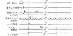
次に、休止状態からの復帰時に基準クロック計数部の計数値を補間するための手段について、図1を基に説明する。
図1において、RxはRTC計数部8の時刻xにおける計数値、Bxは基準クロック計数部5の時刻xにおける計数値である。Next, a means for interpolating thecount value of thereference clock counter when returning from the sleep state will be described with reference to FIG.
In FIG. 1, Rx is a count value at time x of the
時刻mから時刻nまでの時間(m〜n)をRTC計数部8で計数した所定時間とすると、RTC計数部8の計数値がRmからRnへと進む間に、基準クロック計数部5の計数値がBmからBnへと進む。TrとTbはそれぞれRTC計数部8の計数周期と基準クロック計数部5の計数周期である。Assuming that the time (m to n) from time m to time n is a predetermined time counted by the
このような関係であるとき、前記所定時間のRTC計数部8のカウント数を(Rn−Rm)とすると、RTC計数部8のカウント数に対する基準クロック計数部5のカウント数の比は次式で表すことができる。
k=(Bn−Bm)/(Rn−Rm) ・・・(1)
またこの比の値kを係数として、休止時間中のRTC計数部8のカウント数に乗じることによって基準クロック計数部5の計数値を推定すると、次式のようになる。
Bw=k×(Rw−Rn)+Bn ・・・(2)
ここで、時刻nでCPU9がストップ信号を出力し、そのことによってRF電源12が遮断されて、基準クロック信号の発生が停止し、時刻wでストップ信号が解除されて、RF電源12が通電されて、TCXO4が基準クロック信号を発生するものとする。In such a relationship, if the count number of the
k = (Bn−Bm) / (Rn−Rm) (1)
Further, when the count value of the reference
Bw = k × (Rw−Rn) + Bn (2)
At this time, the
上記(1)式のkはRTC計数部8の1カウントあたりの基準クロック計数部5のカウント数であり、このkを(2)式によりRTC計数部8の休止中のカウント数(Rw−Rn)に乗じることで、休止時間にも仮に基準クロック計数部5がカウントするとした場合の、その計数値を予測することができる。そして、この値を(2)式のように休止前の基準クロック計数部5の値に加えることで、休止状態からの復帰時の基準クロック計数部5の値を予測することができる。そして、休止状態から復帰した時に、基準クロック計数部5の値は上記Bwに置き換えられる。このように、休止直前に(1)式を用いてkを求めることにより、低周波クロックのドリフトにより生じた、周波数の初期偏差や温度変動の影響を少なくすることができる。 K in the above equation (1) is the number of counts of the reference
次に、復帰後に衛星からの測位用信号に重畳されたC/Aコードを観測して、そのC/Aコードのコード位相に基づいて基準クロック計数部の計数値を補正する手段について説明する。 Next, means for observing the C / A code superimposed on the positioning signal from the satellite after returning and correcting the count value of the reference clock counter based on the code phase of the C / A code will be described.
本実施形態の受信装置は、休止状態からの復帰後に各衛星の測位を行う際にC/Aコード位相を観測する。また同時に、各衛星の軌道情報と基準クロック計数部5の計数値に基づく時刻とから衛星までの距離を推測し、C/Aコード位相を推測する。推測により得られたC/Aコード位相と観測により得られたC/Aコード位相とのずれは、通常、基準クロックの精度が充分に高く変動が小さいために、基準クロックの変動による影響を無視でき、低周波クロックの変動のみにより生じたものとみなすことができる。The receiving apparatus of the present embodiment observes the C / A code phase when positioning each satellite after returning from the dormant state. At the same time, the distance to the satellite is estimated from the orbit information of each satellite and the time based on thecount value of the
そのため、このC/Aコード位相のずれにより、その位相差に相当する基準クロックのクロック数を求めるとともに、基準クロック計数部の計数値を前記クロック数により補正して置き換えるとともに、次回の間欠動作時の前述の(1)式のk値を補正するためにも用いる。k値の補正は、たとえば以下のように行う。
単位時間あたりの低周波クロックのずれを求めることでkの値は補正することができる。計数値のずれをD、C/Aコード位相の観測による基準クロック計数部の計数値をBp′、低周波クロックにより補正された基準クロック計数部の計数値をBpとする。
D=Bp′−Bp ・・・(3)
また単位時間当たりの低周波クロックのずれ量dは、
d=D/(Rw−Rn) ・・・(4)
この単位時間当たりの低周波クロックのずれ量dにより次回の間欠動作時のk値を補正する。
k′=k+d ・・・(5)
次回の間欠動作からの復帰時には、(2)式のkの値の代わりにk′の値を用いることで低周波クロックの間欠動作中のずれを補正し、より高精度に基準クロック計数値の補間を行うことができる。Therefore, the C / A code phase shift determines the number ofreference clocks corresponding to the phase difference, corrects and replaces the count value of the reference clock counting unit with the number of clocks, and performs the next intermittent operation. This is also used to correct the k value of the above-mentioned equation (1). The k value is corrected as follows, for example.
The value of k can be corrected by obtaining the shift of the low frequency clock per unit time. Assume that the deviation of the count value is D, the count value of the reference clock counter by observation of the C / A code phase is Bp ′, and the count value of the reference clock counter corrected by the low frequency clock is Bp.
D = Bp′−Bp (3)
Also, the amount of deviation d of the low frequency clock per unit time is
d = D / (Rw−Rn) (4)
The k value at the time of the next intermittent operation is corrected based on the shift amount d of the low frequency clock per unit time.
k ′ = k + d (5)
When returning from the next intermittent operation, the value during the intermittent operation of the low-frequency clock is corrected by using the value of k ′ instead of the value of k in equation (2), and the reference clock count value can be calculated with higher accuracy. Interpolation can be performed.
なお、上述のようにC/Aコードをもとに基準クロック計数部の計数値を補正する以外に複数の衛星による測位と同時に得た測位系時刻に基づいて基準クロック計数部の計数値の補正を行ってもよく、その際には、上述の(3)に代えて以下の(3′)式を用いる。測位に基づく測位系時刻をx、その測位系時刻に相当する基準クロックの計数値をBx、休止動作中に低周波クロックによって補正された時刻をy、その時刻による基準クロックの計数値をByとする。
D=Bx−By ・・・(3′)
この(3′)式を代用することにより、複数衛星による測位に基づく測位系時刻により低周波クロックのずれを補正し、高精度に基準クロック計数値の補間を行うことができる。In addition to correcting the count value of the reference clock counter based on the C / A code as described above, the count value of the reference clock counter is corrected based on the positioning system time obtained simultaneously with the positioning by a plurality of satellites. In this case, the following equation (3 ′) is used instead of the above-described (3). The positioning system time based on positioning is x, the count value of the reference clock corresponding to the positioning system time is Bx, the time corrected by the low frequency clock during the pause operation is y, and the count value of the reference clock at that time is By To do.
D = Bx−By (3 ′)
By substituting the equation (3 ′), it is possible to correct the shift of the low frequency clock by the positioning system time based on the positioning by a plurality of satellites, and to perform the interpolation of the reference clock count value with high accuracy.
なお、ほかにも観測で得られるドプラー周波数などの観測データと、その観測データを推定して得た推定データとのずれに基づき基準クロック計数部5の計数値のずれを求めて、高精度に基準クロック計数値の補間を行うことができる。その際には、上述の(3)に変えて以下の(3″)式を用いる。観測に基づくドプラー周波数と、休止動作中に低周波クロックによって補正された時刻に基づいて予測したドプラー周波数との差に相当する基準クロックのクロック数Dを用いる。観測により得られたドプラー周波数に相当する基準クロックの計数値をBa、休止動作中に低周波クロックによって補正された時刻に基づいて予測したドプラー周波数に相当する基準クロックの計数値をBbとする。
D=Ba−Bb ・・・(3″)
この(3″)式を代用することにより、複数衛星による測位に基づく測位系時刻により低周波クロックのずれを補正し、高精度に基準クロック計数値の補間を行うことができる。Incidentally, the observation data such as Doppler frequency obtained by theobservation in addition, the deviation of the count value of thereference
D = Ba−Bb (3 ″)
By substituting this equation (3 ″), it is possible to correct the shift of the low frequency clock by the positioning system time based on the positioning by a plurality of satellites, and to perform the interpolation of the reference clock count value with high accuracy.
次に、間欠動作を実現するための制御部の構成と動作について、図3〜図5を参照して説明する。
図3は制御部のブロック図であり、図4・図5は、図3中の各信号のタイミングチャートである。Next, the configuration and operation of the control unit for realizing the intermittent operation will be described with reference to FIGS.
FIG. 3 is a block diagram of the control unit, and FIGS. 4 and 5 are timing charts of signals in FIG.
図3において、32.768kHzで発振するXO6のクロック信号は分周器7で32分周されて、1.024kHzの低周波クロック信号となる。RTC計数部8はこの低周波クロック信号を計数する。 In FIG. 3, the clock signal of XO6 oscillating at 32.768 kHz is divided by 32 by the
また、16.3678MHzの基準クロック信号を発生するTCXO4が作動している間、基準クロック計数部5はこの基準クロック信号を計数する。Further, while the
ラッチ46は分周器7から出力される1.024kHzの低周波クロック信号の立ち上がりタイミングをラッチ信号として基準クロック計数部5の計数値をラッチする。したがって、CPUは、このラッチ46の値を読み取ることによって、直前の上記低周波クロック信号のタイミングにおける基準クロック計数部5の計数値を得る。 The
時刻レジスタ45は、休止状態から復帰する時刻を定めるためのレジスタである。CPUは休止前に次回の復帰時刻をこの時刻レジスタ45に書き込んだ後、休止状態にする。 The time register 45 is a register for determining the time to return from the hibernation state. The CPU writes the next return time in the time register 45 before the suspension, and then enters the suspension state.
休止状態でも、図2に示したRTC部11は動作を継続しているので、そのRTC計数部8内にある比較器51はRTC計数部8の計数値と時刻レジスタ45に設定された時刻とに基づく一致判定を行う。これが一致すれば、比較器51はCPUへ割り込み信号を与える。この割り込み信号によってCPUは起動開始する。Since the
この休止状態からの復帰時には、CPUは先ず(2)式で求めた計算上の計数値Bwを求め、それを補間レジスタ49に書き込む。その後、CPUはロード制御回路50に対して書込み信号を与える。これによりロード制御回路50は、分周器7からの低周波クロック信号をロード信号として基準クロック計数部5へ与える。基準クロック計数部5は、このロード信号の立ち上がりタイミングで、補間レジスタ49の値をロードする。このことによって、休止状態からの復帰直後に基準クロック計数部5の計数値を正確な値に復帰させることができる。すなわち、基準クロック計数部5が休止しなかった場合に得られる計数値に近似した値を復元できる。その結果、復帰直後の受信機側で持つGPS時刻の精度が高まり、復帰後最初の測位までに要する時間を短縮化できる。 When returning from the sleep state, the CPU first obtains the calculated count value Bw obtained by equation (2) and writes it in the
図4は基準クロック計数部5の計数値をラッチ46へラッチする際のタイミングチャートである。
この図4に示すように、基準クロック計数部5は計数値が1ずつ増加していく。またRTC計数部8の計数値も1ずつ増加していく。図3に示したように、分周器7から出力される低周波クロック信号がラッチ信号であり、この立ち上がりで、基準クロック計数部5の計数値がラッチ46にラッチされる。FIG. 4 is a timing chart when the count value of the
As shown in FIG. 4, the
これにより、次のラッチタイミングまでの間にCPU9はラッチ46の値を読み取ることによって、直前の上記低周波クロック信号のタイミングにおける基準クロック計数部5の計数値を参照することができる。 Thus, until the next latch timing, the
図5は基準クロック計数部5へ補間データをロードする際のタイミングチャートである。
この図5に示すように、まず、CPU9はデータバス上に補間データを乗せ、書き込み信号を出力する。このことにより補間データが補間レジスタ49に書き込まれる。また、ロード制御回路50は上記書き込み信号を受けたことにより、ラッチ信号をロード信号として基準クロック計数部5へ与える状態となる。したがって、その後発生されるロード信号によって、補間レジスタ49の値が基準クロック計数部5にロードされる。FIG. 5 is a timing chart when the interpolation data is loaded into the
As shown in FIG. 5, first, the
また、CPU9からの書き込みが無い場合には、ロード信号が発生されないので、補間データレジスタ49の値が基準クロック計数部5に書き込まれることはない。このことによって基準クロック計数部は基準クロックを正しく計数することができる。Further,when there is no writing from the
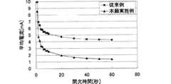
次に、本実施形態の電流消費量と従来例の基準クロック信号発生回路を動作させたまま間欠動作を行う場合の電流消費量について図6・図7を基に説明する。
図6(a)は間欠動作時の消費電流の計算モデルを示している。また、図6(b)は、本実施形態における間欠動作の際に、基準クロック信号発生回路を停止状態にした場合の平均消費電流を示している。また、図6(c)は引用文献1のように、各回路を動作させた場合(以下、従来例という。)の平均消費電流を示している。図7はこの図6(b)(c)の平均電流について、それをグラフとして表したものである。Next, the current consumption amount in the case of performing the intermittent operation while operating the current consumption amount of the present embodiment and the reference clock signal generation circuit of the conventional example will be described with reference to FIGS.
FIG. 6A shows a calculation model of current consumption during intermittent operation. FIG. 6B shows the average current consumption when the reference clock signal generation circuit is stopped during the intermittent operation in the present embodiment. FIG. 6C shows the average current consumption wheneach circuit is operated (hereinafter referred to as a conventional example) as in thecited
ここでは、基準クロック信号発生回路である、16.368MHzの高周波を発振するTCXOが4mAの電流を消費し、また低周波クロック信号発生回路の一部である水晶発振器(XO)が、32kHzで発振し、1mAの電流を消費するものとしている。 Here, the reference clock signal generation circuit TCXO that oscillates a high frequency of 16.368 MHz consumes 4 mA of current, and the crystal oscillator (XO) that is a part of the low frequency clock signal generation circuit oscillates at 32 kHz. And 1 mA of current is consumed.
間欠動作を行うGPS受信装置では、サーチをしている時間T1ではサーチ電流I1が流れ、測位をしている時間T2では電流I2流れ、例えば測位結果のデータをデータ収集局へ無線送信している時間T3では電流I3が流れ、休止時間T4では休止電流I4が流れる。これらの時間T1〜T4の合計が間欠周期Toである。
また、図6(b),(c)において、「クロックずれ」は休止状態からの復帰時に基準クロック計数部5に計数値を復元した際の、連続動作させた場合の正確な計数値からの誤差である。In a GPS receiver that performs an intermittent operation, a search current I1 flows during a search time T1, and a current I2 flows during a positioning time T2, for example, positioning result data is wirelessly transmitted to a data collection station. At time T3, current I3 flows, and at rest time T4, rest current I4 flows. The sum of these times T1 to T4 is the intermittent period To.
6 (b) and 6 (c), the “clock deviation” is the difference from the accurate count value in the case of continuous operation when the count value is restored to the
ここで図6(c)と図6(b)とを比較すると、本実施形態では従来例に対し、クロックずれが増加するために、サーチ時間T1が増加する。また、休止中には消費電流の少ない低速の水晶発振器(XO)を備えたRTC部のみ通電しているので、休止中の休止電流I4が減少する。 Here, when FIG. 6C is compared with FIG. 6B, the clock time is increased in the present embodiment compared to the conventional example, so that the search time T1 is increased. Further, since only the RTC section having the low-speed crystal oscillator (XO) with low current consumption is energized during the pause, the pause current I4 during the pause is reduced.
本願実施例では、休止時間中、基準クロック信号発生回路である温度補償型水晶発振器(TCXO)4を停止することにより、このTCXO4と、基準クロック信号で動作するディジタル処理回路部10での休止電流I4を少なくすることができ、休止時間中の電流消費を極めて小さく抑えることができる。そのため、間欠周期全体としての消費電流量を低減でき、従来より少ない消費電力で間欠動作を行うGPS受信装置が得られる。 In this embodiment, by stopping the temperature compensated crystal oscillator (TCXO) 4 which is the reference clock signal generation circuit during the pause time, the pause current in the digital
なお、本願実施例では、間欠周期Toが長くなるにつれて、「クロックずれ」が大きくなり、それにともなってサーチ時間が増加してしまう。しかし、間欠周期に比べ、サーチ時間の増加分は非常に小さく、例えば1分間間欠動作を行うときでさえ1.5秒のサーチ時間しか要しない。この1.5秒というサーチ時間は、充分に実用に耐えうるサーチ性能であり、そのため、本発明のGPS信号受信装置は、休止電力を大幅に抑制するために、基準クロック信号発生回路を休止させてしまった場合でも、休止状態からの復帰後、速やかに測位を行うことができるものである。
In the embodiment of the present application, as the intermittent period To becomes longer, the “clock shift” becomes larger, and the search time increases accordingly. However, the increase in the search time is very small compared to the intermittent period, and only 1.5 seconds of search time is required even when the intermittent operation is performed for 1 minute, for example. The search time of 1.5 seconds is a search performance that can be sufficiently put into practical use. Therefore, the GPS signal receiver of the present invention pauses the referenceclock signal generation circuit in order to greatly suppress the pause power. Even if it has been, positioning can be performed promptly after returning from the hibernation state.
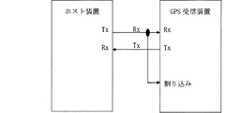
これまでに説明した例では、図2に示したCPU9がRTC部からのタイマー割り込みによって、休止状態から復帰する場合について示した。CPU9はこのGPS受信装置外部の装置からの信号によって復帰することもできる。その例を図8・図9を基に説明する。 In the example described so far, the case where the
図8は、GPS受信装置とそれに接続したホスト装置とからなるシステムの構成を示している。また、図9は図8に示したGPS受信装置の状態とホスト装置から受信するコマンドとの関係を示している。 FIG. 8 shows the configuration of a system including a GPS receiver and a host device connected thereto. FIG. 9 shows the relationship between the state of the GPS receiver shown in FIG. 8 and the command received from the host device.
図8に示すように、ホスト装置とGPS受信装置とはシリアルデータラインで接続していて、GPS受信装置の制御信号受動部のデータ受信信号を、図2に示したCPU9の割り込み信号に兼用している。そのため、GPS受信装置の制御信号受動部がホスト装置から休止時間に制御コマンドを受けると、GPS受信装置は休止状態から復帰する。 As shown in FIG. 8, the host device and the GPS receiver are connected by a serial data line, and the data reception signal of the control signal passive part of the GPS receiver is also used as the interrupt signal of the
ホスト装置から送信される制御コマンドは、先頭から一定ビット数以上後方から始まるビット列が有意な制御コードとなっていて、先頭から一定数のビット列が送受信される間の時間が前記復帰処理の要する時間にマージンを加えた時間となるように、前記先頭から上記有意な制御コードが始まるまでのビット数を設定しておく。このことで、ホスト装置がこのGPS受信装置の状態(休止状態であるか、通常動作状態であるか等)を把握したり、復帰処理が終わり、コマンドを受付可能となるまでの時間を把握したりする必要が無くなる。なお、前記先頭から有意な制御コードが始まるまでのビットは、ランダムコードとして記述してもよい。 In the control command transmitted from the host device, a bit string starting from the rear of a certain number of bits from the beginning is a significant control code, and the time required for the restoration process is the time between transmission and reception of a certain number of bit strings from the beginning. The number of bits from the beginning to the start of the significant control code is set so that a time is added to the margin. This makes it possible for the host device to know the status of the GPS receiver (whether it is in a dormant state or a normal operating state, etc.) or to know the time until the return process is complete and commands can be accepted. There is no need to The bits from the beginning to the beginning of a significant control code may be described as a random code.
このように、休止状態から復帰が完了して、コマンドの解読が可能な状態となるまでの時間と、通信速度とに対応付けて決定したデータサイズよりも大きなサイズのコードを制御コードより前に用いることで、復帰専用の制御線や制御回路を要することなく、GPS受信装置を備えたシステムを容易に構成できる。 In this way, a code having a size larger than the data size determined in association with the time until the command can be decoded after completion of the return from the sleep state and the communication speed is set before the control code. By using it, a system including a GPS receiver can be easily configured without requiring a return-only control line or control circuit.
1 RFコンバータ処理部
2 アンテナ
3 ディジタルベースバンド信号処理部
4 温度補償型水晶発振器(TCXO)
5 基準クロック計数部
6 水晶発振器(XO)
7 分周器
8 RTC計数部
9 CPU
10 ディジタル処理回路部
11 RTC部
12 RF電源
45 時刻レジスタ
46 ラッチ
49 補間レジスタ
50 ロード制御回路
51 比較器1
5
7
DESCRIPTION OF
Claims (5)
Translated fromJapanese前記低周波クロック信号発生回路を動作させたまま、前記基準クロック信号発生回路の動作を所定の休止時間だけ休止状態にし、且つ休止時間終了後に前記休止状態から復帰させる間欠動作を繰り返す間欠動作制御手段と、
前記休止時間前の所定時間での、前記第1のクロック信号のカウント数を前記第2のクロック信号のカウント数で除算することによりカウント比を求めるカウント比決定手段と、
前記所定時間の終了時から前記休止時間終了時までの前記第2のクロック信号のカウント数に前記カウント比を乗算して、前記休止時間終了時の前記基準クロック計数部の計数値を算出し、当該計数値に置き換える基準クロック計数値補間手段と、を備えたことを特徴とする測位用信号受信装置。A reference clock signal generating circuit for generating a first clock signal having a first frequency belonging to a high frequency region of the MHz band, which is a reference signal used for processing a positioning signal, and a reference clock for counting the first clock signal A second clock signal that is a second frequency belonging to a low frequency region in a kHz band lower than the frequency of the first clock signal is supplied independently from the counting unit and the first clock signal, and the power consumption is A low frequency clock signal generation circuit smaller than the reference clock signal generation circuit, a low frequency clock counting unit for counting the second clock signal, a receiving unit for receiving the positioning signal, and a positioning signal based on the positioning signal. An arithmetic processing unit for performing positioning calculation on
Intermittent operation control means for repeating the intermittent operation for putting the operation of the reference clock signal generation circuit into a resting state for a predetermined resting time and returning from the resting state after the resting time ends while the low-frequency clock signal generating circuit is operated. When,
Count ratio determining means for obtaining a count ratioby dividing the count numberof the first clock signal by the count numberof the second clock signal at a predetermined time before the pause time;
Said multiplying the count ratio ofthe count number ofthe second clock signalof a predetermined time from the end to the end the pause timeto calculate the count value of the reference clock counting unitbefore Symbol downtime end, positioning signal receiving apparatus is characterized in that anda reference clock count value interpolation meansfor replacing on the count value.
前記基準クロック計数部の計数値に対応する受信機側の時刻と前記測位手段により求めた前記測位系の時刻との差を求め、当該時刻の差に相当する前記基準クロック計数部のオフセット分だけ当該基準クロック計数部の計数値を補正する基準クロック計数値補正手段と、を備えた請求項1または2に記載の測位用信号受信装置。After returning from the dormant state, each of the positioning signals from a plurality of satellites is received and a positioning calculation is performed, and positioning means for determining the time of the positioning system together with the position of the receiving point;
The difference between the time on the receiver side corresponding to the count value of the reference clock counting unit and the time of the positioning system obtained by the positioning unit is obtained, and only the offset of the reference clock counting unit corresponding to the difference in the time is obtained. The positioning signal receiving device according to claim 1, further comprising reference clock count value correcting means for correcting the count value of the reference clock counting unit.
復帰させる復帰処理を行い、該復帰処理終了後に前記制御コマンドに含まれる制御コードの受付状態となる制御コマンド受動部を備え、
前記起動処理を行う制御コマンドは、前記先頭ビットから一定ビット数以上後方から始まるビット列が有意な制御コードである請求項1〜4のいずれかに記載の測位用信号受信装置。A control command from the outside is received by the serial input unit, and a return process for detecting the first bit of the control command to return the reference clock signal generation circuit from a sleep state is included in the control command after the return process is completed. A control command passive unit that is in a reception state of the control code to be received,
5. The positioning signal receiving apparatus according to claim 1, wherein the control command for performing the activation process is a significant control code in which a bit string starting from the rear of a certain number of bits from the first bit is significant.
Priority Applications (3)
| Application Number | Priority Date | Filing Date | Title |
|---|---|---|---|
| JP2004368432AJP4769452B2 (en) | 2004-12-20 | 2004-12-20 | Positioning signal receiver |
| US11/303,926US7500125B2 (en) | 2004-12-20 | 2005-12-19 | Positioning signal receiving apparatus |
| CN2005101377186ACN1794008B (en) | 2004-12-20 | 2005-12-19 | Positioning signal receiving device |
Applications Claiming Priority (1)
| Application Number | Priority Date | Filing Date | Title |
|---|---|---|---|
| JP2004368432AJP4769452B2 (en) | 2004-12-20 | 2004-12-20 | Positioning signal receiver |
Publications (3)
| Publication Number | Publication Date |
|---|---|
| JP2006177680A JP2006177680A (en) | 2006-07-06 |
| JP2006177680A5 JP2006177680A5 (en) | 2008-02-14 |
| JP4769452B2true JP4769452B2 (en) | 2011-09-07 |
Family
ID=36731937
Family Applications (1)
| Application Number | Title | Priority Date | Filing Date |
|---|---|---|---|
| JP2004368432AExpired - Fee RelatedJP4769452B2 (en) | 2004-12-20 | 2004-12-20 | Positioning signal receiver |
Country Status (3)
| Country | Link |
|---|---|
| US (1) | US7500125B2 (en) |
| JP (1) | JP4769452B2 (en) |
| CN (1) | CN1794008B (en) |
Families Citing this family (46)
| Publication number | Priority date | Publication date | Assignee | Title |
|---|---|---|---|---|
| US7889125B2 (en)* | 2005-03-15 | 2011-02-15 | Honeywell International Inc. | Adjusting processor clock information using a clock drift estimate |
| EP1777540B1 (en)* | 2005-10-21 | 2009-08-12 | Qualcomm Incorporated | Radiolocalization receiver and signal processor |
| CN101454788A (en)* | 2006-05-31 | 2009-06-10 | 株式会社半导体能源研究所 | Semiconductor device and IC label, IC label and IC card having such semiconductor device |
| US8077012B2 (en)* | 2006-06-16 | 2011-12-13 | Intelleflex Corporation | RFID device with first clock for data acquisition and/or calibration of second clock |
| US20080106344A1 (en)* | 2006-09-05 | 2008-05-08 | Tobias Frankenhauser | Circuit arrangement for a gps system |
| WO2008139275A1 (en)* | 2007-05-11 | 2008-11-20 | Freescale Semiconductor, Inc. | System and method for secure real time clocks |
| AU2008251024B2 (en)* | 2007-05-15 | 2013-01-24 | Chronologic Pty Ltd | USB based synchronization and timing system |
| US9721315B2 (en)* | 2007-07-13 | 2017-08-01 | Cerner Innovation, Inc. | Claim processing validation system |
| US20090045945A1 (en)* | 2007-08-13 | 2009-02-19 | Hsin-Chung Yeh | Multi-oscillator apparatus for reduced power consumption and related method thereof |
| WO2010075647A1 (en)* | 2008-12-30 | 2010-07-08 | Mediatek Inc. | Methods and apparatus for obtaining gnss time in a gnss receiver |
| US20090224974A1 (en)* | 2008-03-04 | 2009-09-10 | Navasic Corporation | Power efficient global positioning system receiver |
| US20100162021A1 (en)* | 2008-12-08 | 2010-06-24 | Kennard Peter | System and method for extending the battery life of a mobile device |
| US8126415B2 (en)* | 2008-06-19 | 2012-02-28 | Broadcom Corporation | Method and system for clock synchronization in a global navigation satellite system (GNSS) receiver |
| US8106821B2 (en) | 2008-06-27 | 2012-01-31 | Qualcomm Incorporated | Methods and apparatuses for use with mode-switchable navigation radio |
| US8154449B2 (en)* | 2008-08-18 | 2012-04-10 | O2Micro International, Ltd. | Signal acquisition systems with applications of general clocks |
| US20100052984A1 (en)* | 2008-08-26 | 2010-03-04 | Xiaoguang Yu | Systems and methods for controlling a satellite navigation receiver |
| US8510589B2 (en)* | 2008-08-29 | 2013-08-13 | Intel Mobile Communications GmbH | Apparatus and method using first and second clocks |
| US8234061B2 (en)* | 2008-10-21 | 2012-07-31 | O2Micro, Inc | Systems and methods for controlling a satellite navigation receiver |
| US8823587B2 (en) | 2008-11-13 | 2014-09-02 | Broadcom Corporation | Method of keeping a GPS receiver in a state that enables rapid signal acquisition |
| US7948434B2 (en)* | 2008-11-13 | 2011-05-24 | Broadcom Corporation | Method and system for maintaining a GNSS receiver in a hot-start state |
| JP2010219751A (en)* | 2009-03-16 | 2010-09-30 | Elpida Memory Inc | Semiconductor device |
| US8446223B2 (en)* | 2009-05-22 | 2013-05-21 | CSR Technology, Inc. | Systems and methods for calibrating real time clock |
| KR101547598B1 (en) | 2009-08-17 | 2015-09-04 | 한국전자통신연구원 | Apparatusand method for receiving signal in global navigation satellite system |
| US8560875B2 (en)* | 2009-09-17 | 2013-10-15 | Avago Technologies General Ip (Singapore) Pte. Ltd. | Apparatus for clock calibrating a less precise second clock signal with a more precise first clock signal wherein the first clock signal is inactive during a sniff mode and the second clock signal is active during a sniff mode |
| US20110071759A1 (en)* | 2009-09-22 | 2011-03-24 | Texas Instruments Incorporated | Performance of a Navigation Receiver Operating in a Power-Save Mode with the Aid of Sensors |
| WO2011057000A1 (en)* | 2009-11-04 | 2011-05-12 | Maxlinear, Inc. | Gps baseband controller architecture |
| US8531333B2 (en) | 2009-12-10 | 2013-09-10 | Maxlinear, Inc. | Intermittent tracking for GNSS |
| WO2011137392A1 (en) | 2010-04-29 | 2011-11-03 | Maxlinear, Inc. | Time synchronization with ambient sources |
| JP5556342B2 (en)* | 2010-05-07 | 2014-07-23 | セイコーエプソン株式会社 | Piezoelectric oscillator, GPS receiver and electronic device |
| JP5267516B2 (en)* | 2010-07-14 | 2013-08-21 | ソニー株式会社 | Receiving device, receiving method, computer program, and portable terminal |
| JP5655419B2 (en)* | 2010-08-04 | 2015-01-21 | ソニー株式会社 | Receiving device, receiving method, and portable terminal |
| JP5263260B2 (en)* | 2010-10-27 | 2013-08-14 | 株式会社デンソー | Positioning device for moving body and car navigation device |
| US8589715B2 (en) | 2011-05-10 | 2013-11-19 | Qualcomm Incorporated | Method and system for correcting timing errors due to thermal changes within a portable computing device |
| JP2013055588A (en)* | 2011-09-06 | 2013-03-21 | Japan Radio Co Ltd | Time adjustment device and time adjustment method |
| JP5968609B2 (en)* | 2011-11-07 | 2016-08-10 | 日本無線株式会社 | Telemeter system and telemeter system control method |
| US9651676B2 (en) | 2013-10-09 | 2017-05-16 | Samsung Electronics Co., Ltd. | Digital real time clock monitor for a GNSS receiver and single pin signalling for power-on reset and wake-up interrupt |
| US9277515B2 (en)* | 2013-11-04 | 2016-03-01 | Samsung Electronics Co., Ltd | Precise time tagging of events over an imprecise link |
| US9766682B1 (en)* | 2014-01-27 | 2017-09-19 | Marvell International Ltd. | Wakeup time system using drift estimation |
| FR3030177B1 (en)* | 2014-12-16 | 2016-12-30 | Stmicroelectronics Rousset | ELECTRONIC DEVICE COMPRISING A WAKE MODULE OF AN ELECTRONIC APPARATUS DISTINCT FROM A PROCESSING HEART |
| JP6772700B2 (en)* | 2016-09-15 | 2020-10-21 | カシオ計算機株式会社 | Positioning equipment, electronic clocks, positioning control methods, and programs |
| US20180225249A1 (en)* | 2017-02-08 | 2018-08-09 | Automatic Labs, Inc. | Application-specific integrated circuit configured to interface with automotive diagnostic port |
| US10588087B2 (en) | 2017-05-26 | 2020-03-10 | Arm Limited | Timer for low-power communications systems |
| US10788883B2 (en)* | 2017-05-26 | 2020-09-29 | Arm Ltd | Timer for low-power communications systems |
| CN111182129B (en)* | 2018-12-17 | 2020-12-25 | 深圳恒芸生泰科技有限公司 | Target position determination method and device and storage medium |
| FR3124867B1 (en) | 2021-06-30 | 2024-10-18 | Stmicroelectronics Grand Ouest Sas | Method of communicating a reference time base in a microcontroller, and corresponding microcontroller integrated circuit. |
| CN114137819B (en)* | 2021-12-06 | 2023-11-03 | 上海珉嵘科技有限公司 | Clock frequency offset adjusting device and method and satellite signal acquisition preprocessing board card |
Family Cites Families (16)
| Publication number | Priority date | Publication date | Assignee | Title |
|---|---|---|---|---|
| US5854605A (en)* | 1996-07-05 | 1998-12-29 | Trimble Navigation Limited | GPS receiver using data bit timing to achieve a fast time to first fix |
| JPH10170626A (en)* | 1996-12-05 | 1998-06-26 | Matsushita Electric Ind Co Ltd | GPS receiver |
| US5893044A (en)* | 1997-01-21 | 1999-04-06 | Motorola Inc. | Real time clock apparatus for fast acquisition or GPS signals |
| US7236810B1 (en)* | 1998-09-30 | 2007-06-26 | Skyworks Solutions, Inc. | Using a low frequency timer to restore timing to a high frequency timer |
| JP3455702B2 (en)* | 1999-08-04 | 2003-10-14 | 日本無線株式会社 | Intermittent positioning method and positioning device |
| JP4543480B2 (en)* | 2000-03-02 | 2010-09-15 | ソニー株式会社 | GPS receiver and GPS positioning method |
| JP2001249174A (en)* | 2000-03-06 | 2001-09-14 | Matsushita Electric Ind Co Ltd | GPS receiver |
| JP2002006022A (en) | 2000-06-26 | 2002-01-09 | Furuno Electric Co Ltd | Receiver for positioning |
| DE60238496D1 (en)* | 2001-10-02 | 2011-01-13 | Sirf Tech Inc | GPS DEVICE AND METHOD FOR USING A TEMPERATURE-COMPENSATED OSCILLATOR TO PERFORM A POSITION FIXATION |
| US6662107B2 (en)* | 2001-10-30 | 2003-12-09 | Sirf Technology, Inc. | Calibrated real time clock for acquisition of GPS signals during low power operation |
| US6985811B2 (en)* | 2001-10-30 | 2006-01-10 | Sirf Technology, Inc. | Method and apparatus for real time clock (RTC) brownout detection |
| JP4120237B2 (en)* | 2002-02-28 | 2008-07-16 | ソニー株式会社 | Demodulator and receiver |
| US6778135B2 (en)* | 2002-11-18 | 2004-08-17 | Rf Micro Devices, Inc. | GPS Receiver |
| JP4164662B2 (en)* | 2003-06-10 | 2008-10-15 | 日本電気株式会社 | Portable terminal and GPS time keeping method |
| US20050145187A1 (en)* | 2003-12-29 | 2005-07-07 | Gray James D. | Asset management of livestock in an open range using satellite communications |
| EP1815265A2 (en)* | 2004-11-12 | 2007-08-08 | U-NAV Microelectronics Corporation | Automatic mode setting and power ramp compensator for system power on conditions |
- 2004
- 2004-12-20JPJP2004368432Apatent/JP4769452B2/ennot_activeExpired - Fee Related
- 2005
- 2005-12-19USUS11/303,926patent/US7500125B2/ennot_activeExpired - Fee Related
- 2005-12-19CNCN2005101377186Apatent/CN1794008B/ennot_activeExpired - Fee Related
Also Published As
| Publication number | Publication date |
|---|---|
| US20060149984A1 (en) | 2006-07-06 |
| JP2006177680A (en) | 2006-07-06 |
| CN1794008B (en) | 2012-02-22 |
| US7500125B2 (en) | 2009-03-03 |
| CN1794008A (en) | 2006-06-28 |
Similar Documents
| Publication | Publication Date | Title |
|---|---|---|
| JP4769452B2 (en) | Positioning signal receiver | |
| JP4191605B2 (en) | A calibrated real-time clock that captures GPS signals during low-power operation | |
| US7084810B2 (en) | Portable terminal and GPS time keeping method | |
| US6985811B2 (en) | Method and apparatus for real time clock (RTC) brownout detection | |
| JP5361228B2 (en) | Positioning method | |
| JP2006314095A (en) | Hybrid navigation satellite receiver / cell phone combination, integrated satellite navigation receiver / communication device combination system comprising a single portable device including a global positioning system receiver unit and a communication transceiver unit, and a navigation receiver; How to limit the number of crystals required for a reference oscillator to two when combining cell phones together | |
| US7412266B2 (en) | Aligning a frame pulse of a high frequency timer using a low frequency timer | |
| US10884134B2 (en) | Timing circuit calibration | |
| CN101655686B (en) | Method and device for compensating clock skew | |
| US20130003626A1 (en) | Oscillator settling time allowance | |
| US20120218146A1 (en) | Dynamic Sleep Time Calculation for GNSS Receiver | |
| JP2023112161A (en) | Satellite radio wave receiver, electronic clock, positioning control method and program | |
| US20090045945A1 (en) | Multi-oscillator apparatus for reduced power consumption and related method thereof | |
| CN115152283B (en) | Method and apparatus for timing error adjustment in a mobile device | |
| JP2008005336A (en) | Reception device, reception processing method, and baseband processor | |
| CN201060266Y (en) | Real time clock circuit for accelerating GPS signal capture | |
| US6047169A (en) | Radio communications device with reference-compensated power down control and methods of operating thereof | |
| US8630386B2 (en) | Clock recovery in a battery powered device | |
| JP2002204176A (en) | Radio receiver |
Legal Events
| Date | Code | Title | Description |
|---|---|---|---|
| A521 | Written amendment | Free format text:JAPANESE INTERMEDIATE CODE: A523 Effective date:20071219 | |
| A621 | Written request for application examination | Free format text:JAPANESE INTERMEDIATE CODE: A621 Effective date:20071219 | |
| A977 | Report on retrieval | Free format text:JAPANESE INTERMEDIATE CODE: A971007 Effective date:20100519 | |
| A131 | Notification of reasons for refusal | Free format text:JAPANESE INTERMEDIATE CODE: A131 Effective date:20100525 | |
| A521 | Written amendment | Free format text:JAPANESE INTERMEDIATE CODE: A523 Effective date:20100726 | |
| RD02 | Notification of acceptance of power of attorney | Free format text:JAPANESE INTERMEDIATE CODE: A7422 Effective date:20100726 | |
| A131 | Notification of reasons for refusal | Free format text:JAPANESE INTERMEDIATE CODE: A131 Effective date:20101207 | |
| A521 | Written amendment | Free format text:JAPANESE INTERMEDIATE CODE: A523 Effective date:20110207 | |
| TRDD | Decision of grant or rejection written | ||
| A01 | Written decision to grant a patent or to grant a registration (utility model) | Free format text:JAPANESE INTERMEDIATE CODE: A01 Effective date:20110614 | |
| A01 | Written decision to grant a patent or to grant a registration (utility model) | Free format text:JAPANESE INTERMEDIATE CODE: A01 | |
| A61 | First payment of annual fees (during grant procedure) | Free format text:JAPANESE INTERMEDIATE CODE: A61 Effective date:20110620 | |
| R150 | Certificate of patent or registration of utility model | Free format text:JAPANESE INTERMEDIATE CODE: R150 | |
| FPAY | Renewal fee payment (event date is renewal date of database) | Free format text:PAYMENT UNTIL: 20140624 Year of fee payment:3 | |
| LAPS | Cancellation because of no payment of annual fees |