JP4768196B2 - Apparatus and method for pointing a target by image processing without performing three-dimensional modeling - Google Patents
Apparatus and method for pointing a target by image processing without performing three-dimensional modelingDownload PDFInfo
- Publication number
- JP4768196B2 JP4768196B2JP2001585011AJP2001585011AJP4768196B2JP 4768196 B2JP4768196 B2JP 4768196B2JP 2001585011 AJP2001585011 AJP 2001585011AJP 2001585011 AJP2001585011 AJP 2001585011AJP 4768196 B2JP4768196 B2JP 4768196B2
- Authority
- JP
- Japan
- Prior art keywords
- projection
- image
- target
- plane
- points
- Prior art date
- Legal status (The legal status is an assumption and is not a legal conclusion. Google has not performed a legal analysis and makes no representation as to the accuracy of the status listed.)
- Expired - Fee Related
Links
Images


Classifications
- G—PHYSICS
- G06—COMPUTING OR CALCULATING; COUNTING
- G06F—ELECTRIC DIGITAL DATA PROCESSING
- G06F3/00—Input arrangements for transferring data to be processed into a form capable of being handled by the computer; Output arrangements for transferring data from processing unit to output unit, e.g. interface arrangements
- G06F3/01—Input arrangements or combined input and output arrangements for interaction between user and computer
- G06F3/017—Gesture based interaction, e.g. based on a set of recognized hand gestures
- G—PHYSICS
- G06—COMPUTING OR CALCULATING; COUNTING
- G06F—ELECTRIC DIGITAL DATA PROCESSING
- G06F3/00—Input arrangements for transferring data to be processed into a form capable of being handled by the computer; Output arrangements for transferring data from processing unit to output unit, e.g. interface arrangements
- G06F3/01—Input arrangements or combined input and output arrangements for interaction between user and computer
- G06F3/03—Arrangements for converting the position or the displacement of a member into a coded form
- G06F3/0304—Detection arrangements using opto-electronic means
- G06F3/0325—Detection arrangements using opto-electronic means using a plurality of light emitters or reflectors or a plurality of detectors forming a reference frame from which to derive the orientation of the object, e.g. by triangulation or on the basis of reference deformation in the picked up image
- A—HUMAN NECESSITIES
- A63—SPORTS; GAMES; AMUSEMENTS
- A63F—CARD, BOARD, OR ROULETTE GAMES; INDOOR GAMES USING SMALL MOVING PLAYING BODIES; VIDEO GAMES; GAMES NOT OTHERWISE PROVIDED FOR
- A63F2300/00—Features of games using an electronically generated display having two or more dimensions, e.g. on a television screen, showing representations related to the game
- A63F2300/10—Features of games using an electronically generated display having two or more dimensions, e.g. on a television screen, showing representations related to the game characterized by input arrangements for converting player-generated signals into game device control signals
- A63F2300/1087—Features of games using an electronically generated display having two or more dimensions, e.g. on a television screen, showing representations related to the game characterized by input arrangements for converting player-generated signals into game device control signals comprising photodetecting means, e.g. a camera
- A63F2300/1093—Features of games using an electronically generated display having two or more dimensions, e.g. on a television screen, showing representations related to the game characterized by input arrangements for converting player-generated signals into game device control signals comprising photodetecting means, e.g. a camera using visible light
Landscapes
- Engineering & Computer Science (AREA)
- General Engineering & Computer Science (AREA)
- Theoretical Computer Science (AREA)
- Human Computer Interaction (AREA)
- Physics & Mathematics (AREA)
- General Physics & Mathematics (AREA)
- Position Input By Displaying (AREA)
- User Interface Of Digital Computer (AREA)
- Image Processing (AREA)
- Image Analysis (AREA)
- Ultra Sonic Daignosis Equipment (AREA)
Description
Translated fromJapanese【0001】
[関連出願への相互参照]
本出願は、本出願にその全体が述べられるのと同様にその全体を参考文献として組み込む以下の出願に関連する。
【0002】
「Multi-modal video target acquisition and re-direction system and method」について2000年1月20日に出願された米国出願番号09/488,028。
【0003】
「Hands-Free Home Video Production Camcorder」について2000年3月21日に出願された米国出願番号09/532,820。
【0004】
「Method and system for gesture based option selection」について2000年12月22日に出願された米国出願番号08/995,823。
【0005】
[発明の背景]
[発明の属する技術分野]
本発明は、画像認識に係り、より詳細には、シーンの3次元モデリングを用いることなく、平面上のターゲット点を指し示すために使用されるポインティングジェスチャの認識に関する。
【0006】
[背景]
ジェスチャ認識によって恩恵を受けることが可能である適用が多くある。適用の例として、例えば、カメラの照準を制御する自然な機構がある。別の適用は、スクリーン上のカーソルを動かすためにハンドジェスチャを使用することである。例えば、指でスクリーン上の対象物を単にポインティングすることによって、将来のスマートテレビジョン上で選択を行うことを想像し得るであろう。マウスは必要でなくなる。
【0007】
ターゲットを指し示すポインティングジェスチャといったジェスチャを解釈するためにシーン画像を使用するビデオに基づいたシステムは、急成長しつつある分野である。コンピュータの速度及び画像処理の速度は、照準合わせ、及び、再照準合わせを可能にするのに非常に好都合な機構をカメラに与えることが可能な程である。ビデオ会議システムにおいて、例えば、ユーザは、ズーム可能なカメラをPTベース上に設置するよう関心の対象物を指し示すことが可能である。このような自動化されたシステムは、例えば、音声命令(「命令‐制御」、各言葉の命令が、例えば、「パン‐左」、「上」、「下」等といった指令に対応する基本的には発話に基づいた記号プロセッサ)、ジョイスティック制御、及び連続的なターゲット追跡といった明確な命令を必要とする従来のシステムより直観的であり、且つ、より制御するのが容易である。このようなシステムでは一般的に、多数の角度視野が組み合わされて、シーンの3次元モデルが作成される。3次元モデルは、その後ユーザが指し示すターゲットを決定するために使用される。
【0008】
カメラの制御を可能にする「スマート」技術を用いる1つのシステムは、「System and Method for Permitting Three-Dimensional Navigation Through a Virtual Reality Environment Using Camera-Based Gesture Inputs」なる名称の1997年12月23日に出願された米国特許出願番号08/996,677に説明される。この特許出願では、内部のカメラが、画像処理技術を用いて背景から人間である被写体の輪郭を区別する装置が説明される。画像処理技術は、背景から被写体を区別することを目的とする。その後、被写体は、パン/チルト/ズーム(PTZ)カメラによって追跡されることが可能である。このようなシステムは、ターゲットの位置を繰り返し決定し、ズームし、且つ、焦点を合わせることが可能であるので、ターゲットは比較的画面の中心にあり続ける。
【0009】
米国特許第5,187,574号に説明されるような別の技術は、バーチャル又は電子ズームと称される。1つ以上の固定カメラからのビデオ情報は、対象物がどの特定のカメラの視野において中心になくても、関心のターゲットが出力ビデオ信号内において常に見えるよう電子的に処理される。抽出及び補間演算によって、追跡処理は固定カメラによって達成されることが可能であり、固定カメラは、PTZカメラよりも一般的に安価である。
【0010】
別のシステムが、Masaaki Fukumoto、Yasuhito Suenaga、及びKenji Maseによる論文「Finger-Pointer’; Pointing interface by Image Processing」に詳細に説明される。この論文中において、著者らは、システムの視野内に配置されるオペレータがターゲットを指し示すようにすることによって、ターゲットに焦点を合わせるようカメラを方向付けるシステムを説明する。システムは、オペレータの指の画像を走査且つ処理し、カメラをその方向に照準を合わせるよう方向付ける。この論文は更に、ポインティングジェスチャ及び音声命令の組合わせを使用するシステムも説明する。単純な音声又はジェスチャ命令を使用することにより、オペレータは、ズームイン又はズームアウト、又は、画面を消去するといった単純な機能をカメラが行うよう導くことが可能である。この論文はその全体が述べられたのと同様に本出願に参考文献として組込まれる。
【0011】
ターゲットを指し示すための従来の技術は一般的に、ビデオシーンの3次元構成物をコンピュータ内で作成することと、ユーザが何を指しているのかを決めるためのターゲット領域を必要とする。これは、多数のカメラと、一般的に非常に複雑であり演算量が多い3次元推論とを必要とするのでセットアップが厄介である。
【0012】
米国特許第5,454,043号に、上述されたような制限を有さない1つの従来技術が記載される。この特許では、ビデオカメラによって手の動きが捕捉され、向きと動きのパターンは、画像処理によって命令に変化される。この技術は、ユーザが異なる場所に立つと、従来技術における3次元モデリングによる解決策では可能であるようにターゲットを指し示すために使用することはできないが、ユーザに、例えば、ビデオスクリーン上のカーソルを、制限された方法で制御することを可能にする利点を有する。
【0013】
現在の技術における状況を考慮すると、ポインティングジェスチャといった方向指示を解釈することが可能であるが、機器及びシーンの構成要素の位置合わせ、及び、シーンの3次元モデリングに関連する集中的な演算を要しないシステムが必要である。
【0014】
[発明の概要]
特定の3次元ターゲットのサブセットは、表面上に配置されるサブセットであり、その形状は予め既知ではない。例えば、投影スクリーンの平らな表面は、話者が指し示す場合のあるターゲットを含んでもよい。他の例は、例えば、棒、指、手の動き等によってポインティングするといった幾つか他の方向指示によって見る人がポイントする又は指し示すビデオスクリーン上のサブ画像である。本発明では、上述されたようなターゲットは、カメラの位置又はターゲットが存在する表面の位置に関する情報を位置合わせに用いることなくシーン画像中に識別することが可能である。表面の形状に関する少なくとも幾つかの情報のみが先験的に必要である。
【0015】
ユーザが指し示すターゲットを決定する方法は、1つの実施例によると、ポインタとターゲット領域の両方を含む少なくとも2つのシーン画像を使用する。この例では、ターゲットは、両方のカメラのシーン画像中に見える位置合わせマーク又は基点を含む平らな面上に配置されると仮定する。ポインティングジェスチャも、両方のシーン中に捕捉される。ポインティングジェスチャは処理され、シーン自体のX−Y座標において線を決定するために必要である程度にまで分析される。これは両方のカメラシーンに行われる。例えば、ユーザの右目と指先と一致する点(ピクセルの単位でのX−Y座標)が使用されてよい。或いは、線は、ジェスチャによって指し示される方向を表すよう画成され得、この線は、その線上の2つの任意の点によって画成され得る。両方のシーンからのこれらの点の照準対はマッピングされる。
【0016】
それぞれの画像は位置合わせマークを用いてモーフィングされ、それにより、画像は、ターゲットが配置される面の外観を正確に模倣する。これにより、3次元推論を全く必要とすることなく、2次元推論のみを使用しターゲットを決定することが可能となる。各画像は、基準面と称されてもよいターゲット面上の全ての点が、基準面上に現れるのと全く同じ位置でその画像中に現れるようモーフィングされる。以下に説明するように、4つの対応点が、画像及び基準面中に識別されると線形位置合わせ変換が計算可能である。基準面上の点が、基準面が真っ直ぐに見られた際に現れるのと等しい相対位置でカメラ画像中に現れるよう変換される。つまり、4つの基点が基準面に矩形パターンで配置されると、これらの4つの基点を斜めに見るカメラ画像は、モーフィングされた画像中に再び矩形を形成するようモーフィングされる。モーフィングは、平面投影変換によって行われ、それにより、シーン中の全ての点は最終的には歪み、原画像中で任意の直線上にある全ての点は、依然として直線上にある。第2の画像も同様にモーフィングされ、2つの画像は合わせられ、各画像の基準面上の基点は、単一の画像に合わされるようにされる。2つの画像は、ユーザが1つのカメラビューにおいてもう1つのカメラビューとは異なる位置に現れるようかなり異なる角度から撮られることが好適である。直線が、各画像におけるユーザの右目と指先の間に引かれ、直線が交わるところがターゲットの位置である。言うまでも無く、上述は単に比喩的に過ぎない。実際の処理は数値により計算され、関心の点のみが変換される。関心の点とは、ユーザの目と指先の画像を結びつける2つの画像中の点である。
【0017】
この取り組み方法は、多数の変形に使用されることが可能である。2つの変形が好適であると考えられる。カメラがユーザの前に配置され、ユーザがカメラに向かって指し示す第1の変形は、ビュースクリーン又はモニタ上の選択を指し示すといったヒューマン/マシーン対話に特に好適である。各カメラから見える平面に向けて指し示す第2の変形は、ビデオ会議といったマルチメディアアプリケーションにおいて有用である。
【0018】
「ピークスルー構成」と称される第1の変形は、例えば、メニュからアイテムを選択する、又は、コンピュータゲームで遊ぶために、TV又はコンピュータモニタを介し通信するのに有用であろうことが想像される。この設計では、1つ又は2つの多角形のアパーチャ(隣り合わせにされる)を有する垂直の不透明の平面が、コンピュータ又はTVモニタの上に、スクリーンと略同一平面上に配置される。他の可能性として、各アパーチャが少なくとも4つの特徴点によって取って代わられる透明の延長面を使用することである。スクリーンとアパーチャ延長部を含む伸ばされた面は、「基準面」と称される。1つ又は2つのカメラが延長面の後ろに置かれ、2つのアパーチャの後ろからユーザを見る。各アパーチャ(又は4つのマーカ点)は、それぞれの画像面において常に完全に見ることが可能である(或いは、2つのカメラは、2つの鏡と、2つの画像を隣り合わせで記録する1つのカメラによって取って代わられてもよい。)最初に(且つ、1回限り)、基準面の歪みのない2次元の外観を表すよう基準面(スクリーン+取り付けられたアパーチャ又はマーカ)の前面画像が、非常に狭い視野(略正投影)で撮られる。この画像は、ターゲットの位置を計算するための基準フレームとなる。
【0019】
必要な画像位置合わせ(モーフィング)変換を計算するために、各画像及び基準フレームにアパーチャ境界が検出される。位置合わせは、画像に2次元線形変換を行うことを含み、その後に、アパーチャ境界は、基準フレームに現れる関係と等しい関係で画像中に現れる。この変換を計算するために4つの点が十分であり、このことは本明細書の他の部分に詳細に説明される。
【0020】
この設計では、ユーザは、カメラを指し示しているところを撮られる。指し示されるターゲットの位置を求めるためには、ユーザの目及び指先を検出することが必要である。指先の検出を容易にするよう、ユーザは明るい色がつけられたシンブルを着用してもよい。シンブルは、遠隔制御器といった他の対話手段に取って代わってよい。指先の検出を容易にすることに追加して、ウェラブルマウスは、多数のユーザのポインティングジェスチャを区別する能力を与えるといったユーザインタフェース目的のための別の利点を有する。従って、異なる色の付いたシンブルを着用する多数のユーザが、同一の又は異なるターゲットを同時に指し示すことが可能である。
【0021】
「ダイレクトビュー構成」と称される第2の変形は、大きなスクリーンを使用するプレゼンテーション又はビデオ会議、或いは、カメラセットアップが一時的又は携帯式である状況において最も有用である。このセットアップでは、ターゲット面又は基準面と、ユーザは、両方のカメラから見ることが可能である。ピークスルー構成と同様に、位置合わせは画像データのみに基づいている。基準面上の4点は各画像中に識別され、位置合わせは、その画像に2次元線形変換を行うことにより行われる。基準面は一般的に、投影スクリーン又はホワイトボードであるので、点は容易に検出可能である。点は、高いコントラストを有する投影から形成され、セットアップを記録するために少しの間使用され、その後、スクリーンから取り除かれることが可能である。或いは、基点マークの代わりに2組の平行線を使用することが可能である。スクリーン又はホワイトボードの境界を使用することが可能である。
【0022】
最終的な段階において、1つの画像が基準フレームとして選択されてよい。位置合わせ変換によって、4つの識別された点が、第1の画像において表れる位置と等しい位置に現れるよう第2の画像にマッピングされる。位置合わせは、基準面ではなく、基準フレームに対し行われ、これはポインティングターゲットの識別には十分である。
【0023】
本発明をより深く理解することが出来るよう、以下の説明的な図面を参照し、特定の好適な実施例に関連して説明する。図面を参照するに、図示される詳細は例示的に過ぎず、本発明の好適な実施例を説明するだけのものであり、本発明の原理及び概念的な面の最も有用且つ容易な説明を与えるものとして示されることを強調する。この点について、本発明の基本的な理解に必要である以上に、本発明の構造的な詳細に関しては詳しくは説明しておらず、当業者は、図面と供に考慮されることによって上述の説明から、本発明の幾つかの形式が実際に具現化されることが明らかになろう。
【0024】
[好適な実施例の詳細な説明]
図1を参照するに、テレビジョン又は投影スクリーン10又は壁(図示せず)といった平らな表面上にあるターゲット25は、ユーザ30によって指し示されている。ターゲット位置は、2つのカメラ35及び40のどちらかの画像中に、以下に説明されるような方法で2つのカメラ35及び40からの画像を組合わせることによって識別することが可能である。図面では、ユーザ30は、ターゲット25をポインティングジェスチャによって指し示していることが示される。尚、実験によって人々がターゲットを指し示すために用いるジェスチャは、例えば、ユーザの指先によるもの、ユーザの右(又は左)目によるものであることが分かっており、ターゲットは直線によって結び付けられる。これは、いずれかのカメラから見たときのターゲットの平面投影は、ユーザの目及び指によって画成される直線の平面投影上にあることを意味する。本発明では、これら2つの平面投影は、カメラ35及び40のいずれかで有り得る共通の平面投影、又は、任意の第3の平面に変換される。
【0025】
図2を参照するに、カメラは、それぞれがポインティング装置、ここでは、ユーザの目90と組み合わされる指先80を捕捉するよう向けられる。更に、各カメラの視野45及び50は、ターゲットが配置される平面上に4つの位置合わせマーク20が見えるようにされる。カメラ35及び40の正確な位置又は照準は本発明の実行に対し重要でない。ただし、本発明の更なる説明の後に明らかとなるように、ターゲット位置の正確さに影響するという限りでは重要である。正確を期すために、カメラ画像は、その分解能及び正確さを(真の平面投影の表すものとして)最大限に使用することが有利である。
【0026】
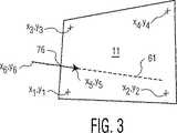
図2及び3を参照するに、ユーザ30の目90及び指先80の位置は、3次元ベクトル(インジケータ)85によって表され、この3次元ベクトル85のカメラ35の画像における平面投影は、2次元ベクトル76として示される。シーンの平面投影の残りの部分では、スクリーン11の画像は、通常の方法で奥行きが縮められることによって歪んでいる。ベクトル76の延長(軌跡)61が示され、これは、そのコンテキストでは既知ではないターゲット25の位置を通過するのに十分に長い。位置合わせマーク20(図1)の座標の投影は、図3の画像において、x1,y1、…、x4,y4として識別される。ベクトル85の投影76の端点は、x5,y5及びx6,y6として識別される。
【0027】
図4及び5を参照するに、ここでも、ユーザ30の目90及び指先80の位置は、3次元ベクトル86によって示される。カメラ40の画像におけるベクトル86の平面投影は、2次元ベクトル87として示される。ここでも、スクリーン12の画像は、通常の方法で奥行きが縮められることにより歪んでいるが、カメラ40の位置及び向きが異なるので歪みは上記と異なる。ベクトル86の延長62が示され、これは、ターゲット25の位置を通過するのに十分に長い。延長62の平面投影は軌跡63として示される。ここでも、ターゲット位置の投影は、予め既知ではない。位置合わせマーク20(図1)の座標の投影は、図5の画像において、p1,q1、…、p4,q4として識別される。ベクトル85の投影87の端点は、p5,q5及びp6,q6として識別される。
【0028】
図6を参照するに、図3の投影の上に、ベクトル86の投影87の変換されたバージョン87´が重ねられる。変換された投影87´は2次元線形変換演算を行うことによって得られ、この演算は、点p1,q1、…、p4,q4が座標x1,y1、…、x4,y4にそれぞれ正確にマッピングされるよう図5の投影をマッピングする。ターゲット位置は、2つの延長線の交点に一致する。
【0029】
この変換は、
【0030】
【数1】
【0031】
【数2】
【0032】
【数3】
【0033】
【数4】
【0034】
上述された実施例では、ターゲットは特定の方法(目対指先)によるポインティングジェスチャによって指し示されるが、他の方法で指し示されてもよい。例えば、照準器又はワンドが使用されてもよい。更に、ターゲットはスクリーン上にあるのではなく、共通の平面に実質的に存在する任意の対象物又は画像であってよい。更に、対象物又はターゲットは単一の平面上に存在しなくてもよく、多数の平面上に存在することも可能であり、各平面は、それぞれ位置合わせマークの組を有する。本発明は更に他の変換を用いて適用される範囲を広げてもよく、それにより、ターゲットは平らな表面以外の表面上に存在することが可能となる。更なる他の変形としては、方向を指し示すためのジェスチャの方法がある。方向を指し示すためのジェスチャをする際の短時間に亘る手又は指の一振りの方向といった方向を得るために時系列の画像を使用することが可能である。更に、別の好適な適用は、ホワイトボードへの適用であり得る。更には、位置合わせマーク20はスクリーン上のマークである必要はなく、スクリーン10の角(かど)であってよい。更に、位置合わせマークは、セットアップの際のある時点においてスクリーン上に投影され、その後、取り除かれてよい。この場合、セットアップが変更されるまで、位置合わせ点の座標は変換を計算するために使用され、位置合わせマークへの更なる参照が必要でなくなる。この技術は、ターゲットにカメラの照準を合わせる際の使用に更に適用することが出来る。基準画像における座標が既知となると、2つのカメラのうちの1つのカメラ、又は、第3のカメラは、ターゲットを得るよう再び照準が合わされ且つズームされる。これは、自動化されたビデオ会議システムのコンテキストにおいて有用である。
【0035】
図7を参照するに、本発明の他の実施例であるセットアップにおいて、ベクトル200はターゲット226を指し示す。延長線205は、ベクトル200の軸に沿ってターゲットに向けられる。前の実施例で説明したように、ベクトル200は、例えば、ポインティングジェスチャといった多数の異なる指示手段のうちのいずれかを表す。他の実施例と同様に、ターゲット226は、平面に、この例では、例えば、大型テレビジョンのスクリーン270に存在する。カメラ235及び240は、それぞれの基準フレーム260及び265を通り照準が合わせられる。基準フレーム260及び265は単に、カメラ235の視野に位置合わせ点1乃至4を、カメラ240の視野に位置合わせ点5乃至8を与える。各カメラ235及び240は、それぞれの位置合わせ点の組とベクトル200が見るよう向けられる。従って、例えば、このセットアップでは、ユーザがテレビジョンの前のいすに座り、テレビジョン上のカメラがユーザに向けられることが可能である。
【0036】
この実施例では、位置合わせマークは単にフレーム260及び265の角1乃至8である。これらの角の座標は、特にビデオカメラといったカメラの有限の分解能を考えると、最高の精度で正確さが得られるようフレームの縁に基づきあてはまる輪郭を推定することにより決定されることが好適である。このような技術は、この技術において既知である。
【0037】
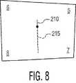
カメラ240の画像を示す図8及びカメラ235の画像を示す図9を参照するに、それぞれ、ポインティングベクトル200のそれぞれの投影210及び220を含む。更に、ベクトル投影210及び220によって指し示される方向によって決められる線215及び225も示される。図7は、3次元シーンを説明するよう使用されたが、この配置は更に、スクリーン270の方に見た際の投影も表す。この画像は、この実施例では、基準画像として使用され、両方のカメラ画像のベクトルはこの基準画像に変換され、基準画像内のターゲットの座標が決定される。
【0038】
図10を参照するに、図7のシーン投影を示し、ベクトル画像が2次元線形変換を用いて基準フレームに変換された後に、線215及び225は、それぞれ線285及び280に変換される。変換によって、図9の画像中の点1乃至4は、図10の画像の対応する点にマッピングされる。しかし、変換される必要のある点は、ベクトル投影210及び220を画成する点だけである。基準画像(フレーム260、265、及び、図7又は図10の基準画像)は、基準点の座標を決定するために、各セットアップに対し1回だけ考慮されればよい。
【0039】
図11を参照するに、本発明の適用を実施するために使用される装置及び処理をブロック図で示す。画像プロセッサ305は、カメラ301及び302から画像データを受け取る。画像及び座標データは、メモリ310又は不揮発性記憶媒体320に格納されてよい。例えば、変換データは、一旦計算されると、不揮発性メモリ320及びメモリ310に格納され、これは、ターゲットの座標x,yを得るようカメラ301及び302からの画像の計算に使用され、その後、アプリケーション処理330に与えられる。アプリケーション処理330は、その後、ホワイトボード上のトレース、又は、ゲームのアバターの制御データといった出力を発生する。
【0040】
尚、カメラ301及び302によって集められる投影データは、ソナー、無線、超音波医用機器、又は、平面投影を形成することが可能である任意の他の装置といった他の情報源からも得られる。
【0041】
当業者には、本発明は上述した実施例の詳細に制限されず、また、本発明は本発明の目的又は本質的な特性から逸脱することなく他の特定の形式で具現化され得ることが明らかであろう。従って、上述される実施例は、どの点においても説明的且つ非制限的であると考えられるべきであり、本発明の範囲は上述された説明ではなく特許請求の範囲によって示され、従って、特許請求の等価物の意味及び範囲内である全ての変更は本発明に含まれるものとする。
【図面の簡単な説明】
【図1】 本発明の1つの実施例に従って、1つのカメラのシーン投影(又は基準投影)上のターゲット位置を、第2のカメラの投影を使用することにより識別するためのセットアップを示す図である。
【図2】 図1の実施例に従って、1つのカメラによって得られる投影に関し説明するためのシーンを示す図である。
【図3】 図2のカメラによって撮られるシーン投影を示す図である。
【図4】 図1の実施例のもう1つのカメラによって得られる投影に関し説明するためのシーンを示す図である。
【図5】 図4のカメラによって撮られるシーン投影を示す図である。
【図6】 ターゲット座標を得るために、図5のシーンから選択される方向を指し示す点が、平面投影変換されることにより、図3のシーンにマッピングされる図である。
【図7】 本発明の別の実施例に従って、2つのカメラからの画像を用いて基準投影上へのターゲット位置の投影を識別するよう使用され、ターゲットを指し示す方向ベクトルを含むシーンを有するセットアップを示す図である。
【図8】 図7の実施例におけるカメラ画像の画像投影を示す図である。
【図9】 図7の実施例におけるカメラ画像の画像投影を示す図である。
【図10】 方向ベクトルによって指し示されるターゲットを識別するために、単一の方向ベクトルの基準画像上への投影の平面投影変換を組合わせた図である。
【図11】 本発明を適用するために用いられてよい装置及び処理を示す図である。[0001]
[Cross-reference to related applications]
This application is related to the following applications, which are incorporated by reference in their entirety as if set forth in their entirety.
[0002]
US Application No. 09 / 488,028 filed on January 20, 2000 for “Multi-modal video target acquisition and re-direction system and method”.
[0003]
US Application No. 09 / 532,820 filed March 21, 2000 for “Hands-Free Home Video Production Camcorder”.
[0004]
US Application No. 08 / 995,823, filed December 22, 2000 for “Method and system for gesture based option selection”.
[0005]
[Background of the invention]
[Technical field to which the invention belongs]
The present invention relates to image recognition, and more particularly to recognition of pointing gestures used to point to target points on a plane without using 3D modeling of the scene.
[0006]
[background]
There are many applications that can benefit from gesture recognition. An example of application is a natural mechanism for controlling the aiming of a camera, for example. Another application is to use hand gestures to move the cursor on the screen. For example, one could imagine making a selection on a future smart television by simply pointing an object on the screen with a finger. The mouse is no longer needed.
[0007]
Video-based systems that use scene images to interpret gestures, such as pointing gestures pointing at a target, are a rapidly growing field. The speed of the computer and the speed of the image processing are such that the camera can be provided with a very convenient mechanism to enable aiming and re-sighting. In a video conferencing system, for example, a user can point an object of interest to place a zoomable camera on the PT base. Such an automated system basically corresponds to, for example, voice commands (“command-control”, each word command corresponds to commands such as “pan-left”, “up”, “down”, etc. Is more intuitive and easier to control than conventional systems that require explicit instructions such as utterance based symbol processors, joystick control, and continuous target tracking. In such systems, a large number of angular views are typically combined to create a three-dimensional model of the scene. The 3D model is then used to determine the target that the user points to.
[0008]
One system that uses “smart” technology to enable camera control was launched on December 23, 1997, named “System and Method for Permitting Three-Dimensional Navigation Through a Virtual Reality Environment Using Camera-Based Gesture Inputs”. This is described in filed US patent application Ser. No. 08 / 996,677. In this patent application, an apparatus is described in which an internal camera distinguishes the contour of a human subject from the background using image processing techniques. Image processing technology aims to distinguish a subject from a background. The subject can then be tracked by a pan / tilt / zoom (PTZ) camera. Such a system can repeatedly determine the position of the target, zoom and focus, so that the target remains relatively centered on the screen.
[0009]
Another technique as described in US Pat. No. 5,187,574 is referred to as virtual or electronic zoom. Video information from one or more fixed cameras is processed electronically so that the target of interest is always visible in the output video signal, regardless of which object is centered in the view of any particular camera. With extraction and interpolation operations, the tracking process can be accomplished with a fixed camera, which is generally less expensive than a PTZ camera.
[0010]
Another system is described in detail in the paper “Finger-Pointer '; Pointing interface by Image Processing” by Masaaki Fukumoto, Yasuhito Suenaga, and Kenji Mase. In this paper, the authors describe a system that directs the camera to focus on a target by having an operator placed in the field of view of the system point to the target. The system scans and processes the image of the operator's finger and directs the camera to aim in that direction. This paper also describes a system that uses a combination of pointing gestures and voice commands. By using simple voice or gesture commands, the operator can guide the camera to perform simple functions such as zooming in or out or erasing the screen. This article is incorporated by reference into this application in the same way as described in its entirety.
[0011]
Conventional techniques for pointing to the target generally require creating a three-dimensional composition of the video scene in the computer and a target area to determine what the user is pointing to. This is cumbersome to set up because it requires a large number of cameras and generally three-dimensional reasoning that is very complex and computationally intensive.
[0012]
US Pat. No. 5,454,043 describes one prior art that does not have the limitations as described above. In this patent, hand movements are captured by a video camera, and orientation and movement patterns are changed to commands by image processing. This technique cannot be used to point the target when the user stands in a different place, as is possible with the 3D modeling solutions in the prior art, but the user can, for example, move the cursor on the video screen. Has the advantage of allowing control in a limited way.
[0013]
Considering the current state of technology, it is possible to interpret direction indications such as pointing gestures, but it requires intensive calculations related to alignment of equipment and scene components and 3D modeling of scenes. A system that does not work is necessary.
[0014]
[Summary of Invention]
A specific subset of a three-dimensional target is a subset placed on a surface, whose shape is not known in advance. For example, the flat surface of the projection screen may include a target that the speaker may point to. Another example is a sub-image on the video screen that the viewer points to or points to with some other direction indication, for example, pointing with a stick, finger, hand movement, etc. In the present invention, targets such as those described above can be identified in a scene image without using information about the position of the camera or the position of the surface on which the target is present for alignment. Only at least some information about the shape of the surface is needed a priori.
[0015]
A method for determining a target to which a user points uses, according to one embodiment, using at least two scene images that include both a pointer and a target area. In this example, it is assumed that the target is placed on a flat surface that includes alignment marks or origins that are visible in the scene images of both cameras. Pointing gestures are also captured in both scenes. The pointing gesture is processed and analyzed to the extent necessary to determine the line in the XY coordinates of the scene itself. This is done for both camera scenes. For example, a point (XY coordinate in pixel units) that matches the user's right eye and fingertip may be used. Alternatively, a line can be defined to represent the direction pointed to by the gesture, and the line can be defined by any two points on the line. These point aim pairs from both scenes are mapped.
[0016]
Each image is morphed with alignment marks so that the image accurately mimics the appearance of the surface on which the target is placed. This makes it possible to determine a target using only two-dimensional reasoning without requiring any three-dimensional reasoning. Each image is morphed so that all points on the target surface, which may be referred to as the reference plane, appear in the image at exactly the same location as they appear on the reference plane. As described below, once four corresponding points are identified in the image and reference plane, a linear registration transformation can be calculated. A point on the reference plane is transformed to appear in the camera image at the same relative position as it appears when the reference plane is viewed straight. That is, when the four base points are arranged in a rectangular pattern on the reference plane, a camera image in which these four base points are viewed obliquely is morphed to form a rectangle again in the morphed image. Morphing is done by planar projection transformation, so that all points in the scene are eventually distorted and all points that are on any straight line in the original image are still on the straight line. The second image is similarly morphed so that the two images are merged so that the base point on the reference plane of each image is merged into a single image. The two images are preferably taken from significantly different angles so that the user appears in one camera view at a different position than the other camera view. A straight line is drawn between the right eye of the user and the fingertip in each image, and the place where the straight line intersects is the target position. Needless to say, the above is merely figurative. The actual process is calculated numerically and only the points of interest are transformed. The point of interest is a point in the two images that connects the user's eyes and the image of the fingertip.
[0017]
This approach can be used for many variations. Two variants are considered suitable. The first variant, in which the camera is placed in front of the user and the user points towards the camera, is particularly suitable for human / machine interaction, such as pointing to a selection on the view screen or monitor. The second variant pointing towards the plane visible from each camera is useful in multimedia applications such as video conferencing.
[0018]
Imagine that the first variant, called “Peak-Through Configuration” would be useful for communicating via a TV or computer monitor, for example to select items from a menu or to play computer games. Is done. In this design, a vertical opaque plane with one or two polygonal apertures (adjacent) is placed on a computer or TV monitor, approximately flush with the screen. Another possibility is to use a transparent extension surface where each aperture is replaced by at least four feature points. The stretched surface including the screen and aperture extension is referred to as the “reference surface”. One or two cameras are placed behind the extension plane and look at the user from behind the two apertures. Each aperture (or four marker points) can always be seen completely in the respective image plane (or two cameras with two mirrors and one camera recording two images side by side) May be replaced.) Initially (and only once) the front image of the reference plane (screen + attached aperture or marker) to represent a two-dimensional appearance without distortion of the reference plane Taken with a narrow field of view (substantially orthographic). This image serves as a reference frame for calculating the target position.
[0019]
Aperture boundaries are detected in each image and reference frame to calculate the necessary image morphing transform. Registration includes performing a two-dimensional linear transformation on the image, after which the aperture boundaries appear in the image in a relationship that is equal to the relationship that appears in the reference frame. Four points are sufficient to calculate this transformation, which is explained in detail elsewhere in this document.
[0020]
In this design, the user is taken while pointing at the camera. In order to determine the position of the target pointed to, it is necessary to detect the user's eyes and fingertips. To facilitate fingertip detection, the user may wear a brightly colored thimble. The thimble may replace other interactive means such as a remote controller. In addition to facilitating fingertip detection, wearable mice have other advantages for user interface purposes, such as providing the ability to distinguish multiple user pointing gestures. Thus, multiple users wearing different colored thimbles can point to the same or different targets simultaneously.
[0021]
The second variant, referred to as “direct view configuration”, is most useful in presentations or video conferencing using large screens, or in situations where the camera setup is temporary or portable. In this setup, the target or reference plane and the user can see from both cameras. Similar to the peak-through configuration, alignment is based only on image data. Four points on the reference plane are identified in each image, and alignment is performed by performing a two-dimensional linear transformation on the image. Since the reference plane is typically a projection screen or whiteboard, the points are easily detectable. Points can be formed from projections with high contrast, used for a short time to record the setup, and then removed from the screen. Alternatively, two sets of parallel lines can be used instead of the base mark. A screen or whiteboard border can be used.
[0022]
In the final stage, one image may be selected as the reference frame. The registration transformation maps the four identified points to the second image so that they appear at a position equal to the position that appears in the first image. The alignment is performed with respect to the reference frame, not the reference plane, which is sufficient for identifying the pointing target.
[0023]
In order that the present invention may be more fully understood, reference is made to the following illustrative drawings and described in connection with certain preferred embodiments. Referring now to the drawings, the details shown are exemplary only, and are merely illustrative of preferred embodiments of the invention and provide the most useful and easy description of the principles and conceptual aspects of the invention. Emphasize what is shown as giving. In this regard, the structural details of the present invention have not been described in detail beyond what is necessary for a basic understanding of the present invention. From the description it will be apparent that several forms of the invention are actually embodied.
[0024]
Detailed Description of Preferred Embodiments
Referring to FIG. 1, a
[0025]
Referring to FIG. 2, the cameras are oriented to capture a
[0026]
2 and 3, the positions of the
[0027]
Referring again to FIGS. 4 and 5, again, the position of the
[0028]
Referring to FIG. 6, a transformed version 87 'of
[0029]
This conversion is
[0030]
[Expression 1]
[0031]
[Expression 2]
[0032]
[Equation 3]
[0033]
[Expression 4]
[0034]
In the embodiment described above, the target is indicated by a pointing gesture by a specific method (eye-to-fingertip), but may be indicated by other methods. For example, a sight or wand may be used. Further, the target may not be on the screen but may be any object or image that is substantially in a common plane. Further, the object or target may not be on a single plane, but can be on multiple planes, each plane having its own set of alignment marks. The present invention may further extend the range of application using other transformations, thereby allowing the target to be on a surface other than a flat surface. Yet another variation is a gesture method for pointing in a direction. Time-series images can be used to obtain a direction, such as the direction of a hand or finger swing over a short period of time when making a gesture to point the direction. Furthermore, another suitable application may be a whiteboard application. Furthermore, the
[0035]
Referring to FIG. 7, in another example setup of the present invention,
[0036]
In this embodiment, the alignment marks are simply corners 1-8 of
[0037]
Referring to FIG. 8 showing an image of
[0038]
Referring to FIG. 10, the scene projection of FIG. 7 is shown, and after the vector image is converted to a reference frame using a two-dimensional linear transformation,
[0039]
Referring to FIG. 11, a block diagram shows an apparatus and process used to implement the application of the present invention. The
[0040]
It should be noted that the projection data collected by the
[0041]
It will be apparent to those skilled in the art that the present invention is not limited to the details of the above-described embodiments, and that the present invention can be embodied in other specific forms without departing from the purpose or essential characteristics of the invention. It will be clear. Accordingly, the above-described embodiments are to be considered in all respects as illustrative and non-limiting, and the scope of the invention is indicated by the following claims rather than by the foregoing description, and thus patents All changes that come within the meaning and range of equivalency of the claims are to be embraced by the invention.
[Brief description of the drawings]
FIG. 1 illustrates a setup for identifying a target position on a scene projection (or reference projection) of one camera by using a projection of a second camera, in accordance with one embodiment of the present invention. is there.
FIG. 2 is a diagram showing a scene for explaining the projection obtained by one camera according to the embodiment of FIG. 1;
FIG. 3 is a diagram showing a scene projection taken by the camera of FIG. 2;
FIG. 4 is a diagram showing a scene for explaining a projection obtained by another camera of the embodiment of FIG. 1;
FIG. 5 is a diagram showing a scene projection taken by the camera of FIG. 4;
6 is a diagram in which a point indicating a direction selected from the scene of FIG. 5 is mapped to the scene of FIG. 3 by plane projection conversion in order to obtain target coordinates.
FIG. 7 illustrates a setup having a scene that includes a direction vector that is used to identify a projection of a target location on a reference projection using images from two cameras, according to another embodiment of the invention. FIG.
FIG. 8 is a diagram showing image projection of a camera image in the embodiment of FIG.
FIG. 9 is a diagram illustrating image projection of a camera image in the embodiment of FIG.
FIG. 10 is a combination of planar projection transformations of projection of a single direction vector onto a reference image to identify the target pointed to by the direction vector.
FIG. 11 shows an apparatus and process that may be used to apply the present invention.
Claims (11)
Translated fromJapanese表示スクリーンと、
ターゲットのインジケータを含むシーンの第1の投影を表す第1の信号を生成する第1の画像収集装置と、
上記シーンの第2の投影を表す第2の信号を生成する第2の画像収集装置と、
を有し、
上記第1の画像収集装置及び上記第2の画像収集装置は、上記表示スクリーンの表面を含む基準面から上記シーンに向けられており、
更に当該平面上のターゲットの位置を求める装置は、
上記第1の信号及び上記第2の信号を受信するよう接続されるコンピュータ装置を含み、
上記コンピュータ装置は、上記第1の信号及び上記第2の信号のうちの少なくとも1つの信号の少なくとも一部に線形変換を行い、上記線形変換の結果を、上記第1の信号及び上記第2の信号のうちのもう一方の信号に組合わせ、それにより、上記シーンの基準投影上の上記基準面内の上記ターゲットの位置を得るようプログラムされ、上記基準投影は、上記シーンの第3の投影、上記第1の投影、及び上記第2の投影のうちの1つである装置。A device for determining the position of a target on a plane,
A display screen;
The first image acquisitiondevice for generating a first signal representing a first projection of a scene that includes an indicatorof the target,
A second image acquisition device forgenerating a second signal representative of a second projection of the scene;
Have
The first image collection device and the second image collection device are directed to the scene from a reference plane including the surface of the display screen,
Furthermore, the device for determining the position of the target on the plane is:
A computer device connected to receive the first signal and the second signal;
The computer apparatus performs linear transformation on at least a part of at least one of the first signal and the second signal, and the result of the linear transformation is converted into the first signal and the second signal. Programmed to obtain the position of the targetin the reference plane on the reference projection of the scene, combined with the other of the signals, the reference projection being a third projection of the scene, An apparatus that is one of the first projection and the second projection.
上記コンピュータ装置は、上記第1の平面投影及び上記第2の平面投影の各々から、それぞれの軌跡を識別するようプログラムされ、
上記コンピュータ装置は、上記第1の平面投影の軌跡及び上記第2の平面投影の軌跡のうちの少なくとも1つの変換を計算し、少なくとも1つの変換された軌跡を形成するよう更にプログラムされ、
上記コンピュータ装置は、上記少なくとも1つの変換された軌跡から、上記第1の平面投影の軌跡及び上記第2の平面投影の軌跡のうちの少なくとも1つと合わされる3次元表面上のターゲットの、上記シーンの上記第1の平面投影及び上記第2の平面投影のいずれか、又は、第3の共通の平面投影上における座標位置を計算するよう更にプログラムされる、装置。2. The apparatus according to claim 1, wherein the first projection and the second projection are a first plane projection and a second plane projection of the scene, and the computer apparatus is the first plane.is projected and programmed to receivethe second planar projection,
Thecomputer device, fromeach of said first planar projection and said second planar projection, is programmed to identifyeach of the trajectories,
Thecomputer apparatus is further programmed to calculate at least one transformation of the first plane projection trajectory and the second plane projection trajectory to form at least one transformed trajectory;
Thecomputer apparatus includes: the scene of a target on a three-dimensional surface that is combined with at least one of the trajectory of the first planar projection and the trajectory of the second planar projection from the at least one transformed trajectory. Anapparatus that is further programmed to calculate a coordinate position on either the first planar projection and the second planar projection, or a third common planar projection.
表示装置の表面に画像を表示する段階であって、上記表面は基準面に存在する、段階と、
上記基準面上にあるターゲットのインジケータの第1の画像及び第2の画像を収集する段階であって、上記第1の画像及び上記第2の画像は上記基準面からシーンを見た像である、段階と、
上記ターゲットの座標を決定するために、上記第1の画像及び上記第2の画像のうちの少なくとも1つに平面投影変換を行う段階と、
を含む方法。A method for determining the position of a target,
Displaying an image on a surface of a display device, wherein the surface is present on a reference plane; and
Comprising the steps of collecting a first image and a second image of the indicatorof targets onthe referenceplane, the first image and the second image is the image viewed scene from the reference plane , The stage ,
To determine the coordinates of the target, and lineCormorant stage planar projection conversion to at least one of the first image and the secondimage,
Including methods.
を含む、請求項3記載の方法。Calculatingplane projection transformation parameters from at least four points ofthe first plane projection and at least four points of the second plane projection;
The method ofclaim 3 comprising:
それぞれの視野から基準面にある点を撮像し、上記それぞれの視野から上記点を上記基準面の対応する点にマッピングするのに有効な変換を得ることにより線形変換を計算する段階と、
上記基準面内の表示面上に画像を表示する段階と、
上記基準面から見た3次元軌跡の第1及び第2の画像を収集する段階と、
上記線形変換のうちの1つを用いて、3次元軌跡の上記第1の画像を変換する段階と、
上記線形変換のうちのもう1つを用いて、上記軌跡の上記第2の画像を変換する段階と、
上記軌跡によって指し示される上記ターゲットの上記基準面内の座標を決めるために、上記変換する段階から結果として得られる上記軌跡の各変換の交点を決定する段階であって、上記ターゲットは上記基準面内にある、段階と、
を含む方法。A method for identifying a target on a plane, comprising:
Calculating a linear transformation by a point from each of the field on the reference plane is imaged, the field of view oral the points of the respective said obtaining valid conversion to map to the corresponding points of the reference plane,
Displaying an image on a display surface within the reference plane;
Collecting first and second images of a three-dimensional trajectory viewed from the reference plane;
Using one of the linear transformation, the step of convertingthe first image of the three-dimensional trajectory,
Using another of the linear conversion, and convertingthe second image of the trajectory,
To determine the coordinates in the reference plane of the target pointed to by the trace,comprising the steps of determining an intersection of each conversion of the trajectory resulting fromthe stepof the conversion, the target is the reference surface Inside,the stage,
Including methods.
上記基準面の上記点の上記投影に反応して変換を得、上記変換は、上記点のそれぞれを、上記第1の表面投影及び上記第2の表面投影のうちのいずれか、又は、第3の面で有り得る結果としての投影面上のそれぞれの点に変換するよう行われ、上記基準面上の所与の点の各投影は、上記結果としての投影面上で同一の座標にある、段階と、
上記ターゲットを識別するために、上記変換を使用し、軌跡の少なくとも1つの投影を変換する段階と、
を含む請求項10記載の方法。Forming at least one first surface projection and a second surface projection of the pointabove Symbol referenceplane,
A transformation is obtained in response to the projection of the point on the referenceplane , the transformation transforming each of the points to either the firstsurface projection or the secondsurface projection , or a third performed to convert as a result be a side to each point on the projection plane, the projection of a given point on the reference plane is in the same coordinate on the projection surface as theresult, step When,
To identify the target, andconverting using the conversion, at least one projection of the trajectory,
The method ofclaim 10 comprising:
Applications Claiming Priority (3)
| Application Number | Priority Date | Filing Date | Title |
|---|---|---|---|
| US57299100A | 2000-05-17 | 2000-05-17 | |
| US09/572,991 | 2000-05-17 | ||
| PCT/EP2001/005186WO2001088681A1 (en) | 2000-05-17 | 2001-05-08 | Apparatus and method for indicating a target by image processing without three-dimensional modeling |
Publications (2)
| Publication Number | Publication Date |
|---|---|
| JP2003533817A JP2003533817A (en) | 2003-11-11 |
| JP4768196B2true JP4768196B2 (en) | 2011-09-07 |
Family
ID=24290197
Family Applications (1)
| Application Number | Title | Priority Date | Filing Date |
|---|---|---|---|
| JP2001585011AExpired - Fee RelatedJP4768196B2 (en) | 2000-05-17 | 2001-05-08 | Apparatus and method for pointing a target by image processing without performing three-dimensional modeling |
Country Status (7)
| Country | Link |
|---|---|
| EP (1) | EP1292877B1 (en) |
| JP (1) | JP4768196B2 (en) |
| KR (1) | KR100869447B1 (en) |
| CN (1) | CN1222859C (en) |
| AT (1) | ATE390664T1 (en) |
| DE (1) | DE60133386T2 (en) |
| WO (1) | WO2001088681A1 (en) |
Families Citing this family (35)
| Publication number | Priority date | Publication date | Assignee | Title |
|---|---|---|---|---|
| US6600475B2 (en) | 2001-01-22 | 2003-07-29 | Koninklijke Philips Electronics N.V. | Single camera system for gesture-based input and target indication |
| EP1507389A1 (en)* | 2003-08-13 | 2005-02-16 | Sony Ericsson Mobile Communications AB | Mobile phone with means for switching off the alarm remotely |
| US7893920B2 (en) | 2004-05-06 | 2011-02-22 | Alpine Electronics, Inc. | Operation input device and method of operation input |
| EP1596271A1 (en)* | 2004-05-11 | 2005-11-16 | Hitachi Europe S.r.l. | Method for displaying information and information display system |
| WO2005119591A1 (en)* | 2004-06-04 | 2005-12-15 | Matsushita Electric Industrial Co., Ltd. | Display control device, display control method, program, and portable apparatus |
| EP1763847A2 (en)* | 2004-06-28 | 2007-03-21 | Koninklijke Philips Electronics N.V. | Image processing system, particularly for images of implants |
| TW200934566A (en)* | 2007-09-07 | 2009-08-16 | Konami Digital Entertainment | Image processor, game device, and computer program |
| JP5120754B2 (en)* | 2008-03-28 | 2013-01-16 | 株式会社国際電気通信基礎技術研究所 | Motion detection device |
| TWI383311B (en)* | 2008-06-02 | 2013-01-21 | Wistron Corp | Multi - touch Inductive Input Device and Its Induction Method |
| KR101652110B1 (en)* | 2009-12-03 | 2016-08-29 | 엘지전자 주식회사 | Controlling power of devices which is controllable with user's gesture |
| CN102033644B (en)* | 2010-01-04 | 2015-07-15 | 张强 | Three-dimensional touch or handwriting screen |
| CN101866235B (en)* | 2010-02-10 | 2014-06-18 | 张强 | Multi-point touch or multi-pen writing screen in three-dimensional space |
| TWI406156B (en)* | 2010-03-12 | 2013-08-21 | Primax Electronics Ltd | Airflow-sensing computer cursor generator and airflow-sensing mouse |
| CN101916437B (en)* | 2010-06-18 | 2014-03-26 | 中国科学院计算技术研究所 | Method and system for positioning target based on multi-visual information |
| CN102004623B (en)* | 2010-11-29 | 2013-02-27 | 深圳市九洲电器有限公司 | Three-dimensional image display device and method |
| KR101151962B1 (en)* | 2011-02-16 | 2012-06-01 | 김석중 | Virtual touch apparatus and method without pointer on the screen |
| KR101381928B1 (en)* | 2011-02-18 | 2014-04-07 | 주식회사 브이터치 | virtual touch apparatus and method without pointer on the screen |
| JP5730086B2 (en)* | 2011-03-18 | 2015-06-03 | Necパーソナルコンピュータ株式会社 | Input device and input method |
| KR20120126508A (en)* | 2011-05-12 | 2012-11-21 | 김석중 | method for recognizing touch input in virtual touch apparatus without pointer |
| KR101235432B1 (en)* | 2011-07-11 | 2013-02-22 | 김석중 | Remote control apparatus and method using virtual touch of electronic device modeled in three dimension |
| KR101330531B1 (en)* | 2011-11-08 | 2013-11-18 | 재단법인대구경북과학기술원 | Method of virtual touch using 3D camera and apparatus thereof |
| CN102520799B (en)* | 2011-12-22 | 2015-03-25 | 胡世曦 | Projection keyboard |
| TWI486820B (en)* | 2012-12-28 | 2015-06-01 | Wistron Corp | Coordinate transformation method and computer system for interactive system |
| CN104714728B (en)* | 2013-02-28 | 2018-10-12 | 联想(北京)有限公司 | A kind of display methods and equipment |
| TW201510771A (en) | 2013-09-05 | 2015-03-16 | Utechzone Co Ltd | Pointing direction detecting device and its method, program and computer readable-medium |
| CN104978012B (en) | 2014-04-03 | 2018-03-16 | 华为技术有限公司 | One kind points to exchange method, apparatus and system |
| KR101453815B1 (en)* | 2014-08-01 | 2014-10-22 | 스타십벤딩머신 주식회사 | Device and method for providing user interface which recognizes a user's motion considering the user's viewpoint |
| JP6124863B2 (en)* | 2014-11-26 | 2017-05-10 | レノボ・シンガポール・プライベート・リミテッド | Method, computer, and computer program for recognizing pointing gesture position |
| WO2017203102A1 (en)* | 2016-05-25 | 2017-11-30 | Valo Motion Oy | An arrangement for controlling a computer program |
| KR102239469B1 (en)* | 2018-01-19 | 2021-04-13 | 한국과학기술원 | Method and apparatus for controlling object |
| WO2019143204A1 (en)* | 2018-01-19 | 2019-07-25 | 한국과학기술원 | Object control method and object control device |
| CN108363485B (en)* | 2018-01-25 | 2021-06-18 | 广州杰赛科技股份有限公司 | Control method, device and system of non-touch screen display terminal and computer equipment |
| KR102191061B1 (en)* | 2019-03-11 | 2020-12-15 | 주식회사 브이터치 | Method, system and non-transitory computer-readable recording medium for supporting object control by using a 2d camera |
| WO2022000149A1 (en)* | 2020-06-28 | 2022-01-06 | 华为技术有限公司 | Interaction method and electronic device |
| CN112419381B (en)* | 2020-12-15 | 2023-03-03 | 山东威高医疗科技有限公司 | Automatic identification method for marker point sequence in X-ray image |
Family Cites Families (9)
| Publication number | Priority date | Publication date | Assignee | Title |
|---|---|---|---|---|
| JP3114813B2 (en)* | 1991-02-27 | 2000-12-04 | 日本電信電話株式会社 | Information input method |
| JP3276010B2 (en)* | 1991-07-15 | 2002-04-22 | 日本電信電話株式会社 | How to enter information |
| JPH0744313A (en)* | 1993-08-03 | 1995-02-14 | Nippon Telegr & Teleph Corp <Ntt> | Instruction information input method |
| JPH07146752A (en)* | 1993-11-22 | 1995-06-06 | Toshiba Corp | Environment model creation device |
| US5768443A (en)* | 1995-12-19 | 1998-06-16 | Cognex Corporation | Method for coordinating multiple fields of view in multi-camera |
| JP3749369B2 (en)* | 1997-03-21 | 2006-02-22 | 株式会社竹中工務店 | Hand pointing device |
| JPH1163927A (en)* | 1997-08-27 | 1999-03-05 | Mitsubishi Heavy Ind Ltd | Head position and posture measuring device, and operation monitoring device |
| JPH11161415A (en)* | 1997-11-28 | 1999-06-18 | Seiko Epson Corp | Input method and input device |
| US6147678A (en)* | 1998-12-09 | 2000-11-14 | Lucent Technologies Inc. | Video hand image-three-dimensional computer interface with multiple degrees of freedom |
- 2001
- 2001-05-08ATAT01949321Tpatent/ATE390664T1/ennot_activeIP Right Cessation
- 2001-05-08KRKR1020027000699Apatent/KR100869447B1/ennot_activeExpired - Fee Related
- 2001-05-08CNCNB01801285XApatent/CN1222859C/ennot_activeExpired - Fee Related
- 2001-05-08EPEP01949321Apatent/EP1292877B1/ennot_activeExpired - Lifetime
- 2001-05-08JPJP2001585011Apatent/JP4768196B2/ennot_activeExpired - Fee Related
- 2001-05-08DEDE60133386Tpatent/DE60133386T2/ennot_activeExpired - Lifetime
- 2001-05-08WOPCT/EP2001/005186patent/WO2001088681A1/enactiveIP Right Grant
Also Published As
| Publication number | Publication date |
|---|---|
| ATE390664T1 (en) | 2008-04-15 |
| KR100869447B1 (en) | 2008-11-21 |
| DE60133386T2 (en) | 2009-04-02 |
| CN1380996A (en) | 2002-11-20 |
| EP1292877A1 (en) | 2003-03-19 |
| KR20020025198A (en) | 2002-04-03 |
| WO2001088681A1 (en) | 2001-11-22 |
| CN1222859C (en) | 2005-10-12 |
| DE60133386D1 (en) | 2008-05-08 |
| EP1292877B1 (en) | 2008-03-26 |
| JP2003533817A (en) | 2003-11-11 |
Similar Documents
| Publication | Publication Date | Title |
|---|---|---|
| JP4768196B2 (en) | Apparatus and method for pointing a target by image processing without performing three-dimensional modeling | |
| JP4278979B2 (en) | Single camera system for gesture-based input and target indication | |
| US6198485B1 (en) | Method and apparatus for three-dimensional input entry | |
| CN100407798C (en) | 3D geometric modeling system and method | |
| US20110292036A1 (en) | Depth sensor with application interface | |
| Lee et al. | 3D natural hand interaction for AR applications | |
| US20110012830A1 (en) | Stereo image interaction system | |
| US20140139429A1 (en) | System and method for computer vision based hand gesture identification | |
| CN102508578B (en) | Projection positioning device and method as well as interaction system and method | |
| US20120319949A1 (en) | Pointing device of augmented reality | |
| US10950056B2 (en) | Apparatus and method for generating point cloud data | |
| Leibe et al. | Toward spontaneous interaction with the perceptive workbench | |
| CN104050859A (en) | Interactive digital stereoscopic sand table system | |
| JP6344530B2 (en) | Input device, input method, and program | |
| CN104281397B (en) | The refocusing method, apparatus and electronic equipment of more depth intervals | |
| CN115100742B (en) | Meta universe exhibition and demonstration experience system based on space-apart gesture operation | |
| CN106814963A (en) | A kind of human-computer interaction system and method based on 3D sensor location technologies | |
| JP2004265222A (en) | Interface method, apparatus, and program | |
| JP3860550B2 (en) | Interface method, apparatus, and program | |
| GB2345538A (en) | Optical tracker | |
| KR20180045668A (en) | User Terminal and Computer Implemented Method for Synchronizing Camera Movement Path and Camera Movement Timing Using Touch User Interface | |
| KR101743888B1 (en) | User Terminal and Computer Implemented Method for Synchronizing Camera Movement Path and Camera Movement Timing Using Touch User Interface | |
| Zhang | Vision-based interaction with fingers and papers | |
| CN112181135B (en) | A 6-DOF visual-tactile interaction method based on augmented reality | |
| US9551922B1 (en) | Foreground analysis on parametric background surfaces |
Legal Events
| Date | Code | Title | Description |
|---|---|---|---|
| A621 | Written request for application examination | Free format text:JAPANESE INTERMEDIATE CODE: A621 Effective date:20080501 | |
| A131 | Notification of reasons for refusal | Free format text:JAPANESE INTERMEDIATE CODE: A131 Effective date:20101130 | |
| A521 | Request for written amendment filed | Free format text:JAPANESE INTERMEDIATE CODE: A523 Effective date:20110228 | |
| TRDD | Decision of grant or rejection written | ||
| A01 | Written decision to grant a patent or to grant a registration (utility model) | Free format text:JAPANESE INTERMEDIATE CODE: A01 Effective date:20110524 | |
| A61 | First payment of annual fees (during grant procedure) | Free format text:JAPANESE INTERMEDIATE CODE: A61 Effective date:20110616 | |
| R150 | Certificate of patent or registration of utility model | Ref document number:4768196 Country of ref document:JP Free format text:JAPANESE INTERMEDIATE CODE: R150 Free format text:JAPANESE INTERMEDIATE CODE: R150 | |
| FPAY | Renewal fee payment (event date is renewal date of database) | Free format text:PAYMENT UNTIL: 20140624 Year of fee payment:3 | |
| R250 | Receipt of annual fees | Free format text:JAPANESE INTERMEDIATE CODE: R250 | |
| R250 | Receipt of annual fees | Free format text:JAPANESE INTERMEDIATE CODE: R250 | |
| R250 | Receipt of annual fees | Free format text:JAPANESE INTERMEDIATE CODE: R250 | |
| R250 | Receipt of annual fees | Free format text:JAPANESE INTERMEDIATE CODE: R250 | |
| R250 | Receipt of annual fees | Free format text:JAPANESE INTERMEDIATE CODE: R250 | |
| LAPS | Cancellation because of no payment of annual fees |