JP4767443B2 - Network storage type video camera system - Google Patents
Network storage type video camera systemDownload PDFInfo
- Publication number
- JP4767443B2 JP4767443B2JP2001204113AJP2001204113AJP4767443B2JP 4767443 B2JP4767443 B2JP 4767443B2JP 2001204113 AJP2001204113 AJP 2001204113AJP 2001204113 AJP2001204113 AJP 2001204113AJP 4767443 B2JP4767443 B2JP 4767443B2
- Authority
- JP
- Japan
- Prior art keywords
- packet
- moving image
- time
- network
- terminal device
- Prior art date
- Legal status (The legal status is an assumption and is not a legal conclusion. Google has not performed a legal analysis and makes no representation as to the accuracy of the status listed.)
- Expired - Fee Related
Links
Images


Classifications
- H—ELECTRICITY
- H04—ELECTRIC COMMUNICATION TECHNIQUE
- H04N—PICTORIAL COMMUNICATION, e.g. TELEVISION
- H04N21/00—Selective content distribution, e.g. interactive television or video on demand [VOD]
- H04N21/20—Servers specifically adapted for the distribution of content, e.g. VOD servers; Operations thereof
- H04N21/27—Server based end-user applications
- H04N21/274—Storing end-user multimedia data in response to end-user request, e.g. network recorder
- H04N21/2747—Remote storage of video programs received via the downstream path, e.g. from the server
- H—ELECTRICITY
- H04—ELECTRIC COMMUNICATION TECHNIQUE
- H04N—PICTORIAL COMMUNICATION, e.g. TELEVISION
- H04N21/00—Selective content distribution, e.g. interactive television or video on demand [VOD]
- H04N21/20—Servers specifically adapted for the distribution of content, e.g. VOD servers; Operations thereof
- H04N21/23—Processing of content or additional data; Elementary server operations; Server middleware
- H04N21/238—Interfacing the downstream path of the transmission network, e.g. adapting the transmission rate of a video stream to network bandwidth; Processing of multiplex streams
- H04N21/2381—Adapting the multiplex stream to a specific network, e.g. an Internet Protocol [IP] network
- H—ELECTRICITY
- H04—ELECTRIC COMMUNICATION TECHNIQUE
- H04N—PICTORIAL COMMUNICATION, e.g. TELEVISION
- H04N21/00—Selective content distribution, e.g. interactive television or video on demand [VOD]
- H04N21/40—Client devices specifically adapted for the reception of or interaction with content, e.g. set-top-box [STB]; Operations thereof
- H04N21/41—Structure of client; Structure of client peripherals
- H04N21/414—Specialised client platforms, e.g. receiver in car or embedded in a mobile appliance
- H04N21/4147—PVR [Personal Video Recorder]
- H—ELECTRICITY
- H04—ELECTRIC COMMUNICATION TECHNIQUE
- H04N—PICTORIAL COMMUNICATION, e.g. TELEVISION
- H04N21/00—Selective content distribution, e.g. interactive television or video on demand [VOD]
- H04N21/40—Client devices specifically adapted for the reception of or interaction with content, e.g. set-top-box [STB]; Operations thereof
- H04N21/41—Structure of client; Structure of client peripherals
- H04N21/426—Internal components of the client ; Characteristics thereof
- H04N21/42661—Internal components of the client ; Characteristics thereof for reading from or writing on a magnetic storage medium, e.g. hard disk drive
- H—ELECTRICITY
- H04—ELECTRIC COMMUNICATION TECHNIQUE
- H04N—PICTORIAL COMMUNICATION, e.g. TELEVISION
- H04N21/00—Selective content distribution, e.g. interactive television or video on demand [VOD]
- H04N21/60—Network structure or processes for video distribution between server and client or between remote clients; Control signalling between clients, server and network components; Transmission of management data between server and client, e.g. sending from server to client commands for recording incoming content stream; Communication details between server and client
- H04N21/61—Network physical structure; Signal processing
- H04N21/6106—Network physical structure; Signal processing specially adapted to the downstream path of the transmission network
- H04N21/6131—Network physical structure; Signal processing specially adapted to the downstream path of the transmission network involving transmission via a mobile phone network
- H—ELECTRICITY
- H04—ELECTRIC COMMUNICATION TECHNIQUE
- H04N—PICTORIAL COMMUNICATION, e.g. TELEVISION
- H04N21/00—Selective content distribution, e.g. interactive television or video on demand [VOD]
- H04N21/60—Network structure or processes for video distribution between server and client or between remote clients; Control signalling between clients, server and network components; Transmission of management data between server and client, e.g. sending from server to client commands for recording incoming content stream; Communication details between server and client
- H04N21/63—Control signaling related to video distribution between client, server and network components; Network processes for video distribution between server and clients or between remote clients, e.g. transmitting basic layer and enhancement layers over different transmission paths, setting up a peer-to-peer communication via Internet between remote STB's; Communication protocols; Addressing
- H04N21/643—Communication protocols
- H04N21/6437—Real-time Transport Protocol [RTP]
- H—ELECTRICITY
- H04—ELECTRIC COMMUNICATION TECHNIQUE
- H04N—PICTORIAL COMMUNICATION, e.g. TELEVISION
- H04N7/00—Television systems
- H04N7/16—Analogue secrecy systems; Analogue subscription systems
- H04N7/173—Analogue secrecy systems; Analogue subscription systems with two-way working, e.g. subscriber sending a programme selection signal
- H04N7/17309—Transmission or handling of upstream communications
- H04N7/17318—Direct or substantially direct transmission and handling of requests
Landscapes
- Engineering & Computer Science (AREA)
- Multimedia (AREA)
- Signal Processing (AREA)
- Computer Networks & Wireless Communication (AREA)
- Television Signal Processing For Recording (AREA)
- Two-Way Televisions, Distribution Of Moving Picture Or The Like (AREA)
- Closed-Circuit Television Systems (AREA)
- Signal Processing For Digital Recording And Reproducing (AREA)
- Studio Devices (AREA)
- Compression Or Coding Systems Of Tv Signals (AREA)
Description
Translated fromJapanese【0001】
【発明の属する技術分野】
本発明は、ネットワーク蓄積型ビデオカメラシステム即ち、ビデオカメラで撮影した映像や音声データを、有線或いは無線の通信ネットワークにより伝送し、ネットワーク上のサーバに蓄積保存するシステムに関するものである。
【0002】
さらに、本発明は、カメラで撮像された動画像データをネットワーク上に蓄積する際、録画終了時の欠損データを修復可能とするネットワーク蓄積型ビデオカメラシステムに関する。
【0003】
【従来の技術】
近年の動画像圧縮技術及びハードウエアデバイス技術の進歩により、デジタル動画像データを扱える民生機器が増えてきている。これらの機器では、大量の動画像データを蓄積するために大容量のハードディスク(HDD)を装備して長時間録画を意図するものがある。一方、逆に数10MBのフラッシュ(FLASH)メモリを蓄積媒体とすることで小型化を図ったものがある。
【0004】
しかし、前者は大容量HDDの搭載のため小型化が難しく、後者は録画時間が短く、記録時間を延ばすためには画質を犠牲にして圧縮率を上げる必要があるといった問題があり、一長一短である。
【0005】
そこで、カメラ端末の小型化と長時間録画の両立のための解決策として、画像蓄積を、端末に内蔵される記録デバイスに行うのではなく、通信機能により接続した外部の記録デバイスに蓄積することが考えられる。記録デバイスを外部に置くことで、カメラ端末の小型化が実現する。また記録デバイスの容量を十分大きいものとすることで、長時間の録画が可能となる。
【0006】
しかし、無線網のようにビットエラーが多く信頼性の低いネットワークを用いて正確にデータを転送するためには、データをパケット化し、通信経路の両端でパケットの到着を監視する。そして、到着していないパケットがあった場合は再送処理を行って、転送の前後でのデータの同一性の保証をする必要がある。
【0007】
これを実現する手段としてARQ(Automatic Repeat Request:自動再送要求)技術がある。ARQはデータをフレームに分割して送信し、誤りフレームがあった場合に再送信の依頼を出すエラーフリー技術である。
【0008】
しかし、ARQ技術により再送処理を行った場合、パケット消失が多い場合は、再送処理によりネットワーク上を再送パケットが頻繁に転送されて帯域を圧迫する。場合によっては輻輳を起こしてデータ転送そのものが不可能になってしまう。このためにARQ技術は、リアルタイムデータ転送には適さないとされている。
【0009】
特にデジタルビデオカメラが生成するデジタル動画像データは、実時間で、且つ絶え間なく生成されるものである。このために輻輳に至らなくても実時間でのデータ転送完了が保証されなければ、送信できないデータがカメラ端末上に溜まってしまい、通信がボトルネックとなり、録画そのものが不可能となる。
【0010】
逆にデータの正確さを犠牲にして実時間での転送を保証するなら、消失したパケットを再送しなければよい。しかし、その場合はカメラが符号化したデータを正確に転送出来ないので、ネットワーク上のサーバに蓄積された動画像データは正確に再生することができなくなる。このことは、デジタルビデオカメラの目的である動画像の記録機能を完全に実現できていないことを意味する。
【0011】
【発明が解決しようとする課題】
したがって、本発明の目的は、動画像データをネットワーク上のサーバに蓄積するネットワーク蓄積型ビデオカメラシステムであって、特に信頼性の低いネットワーク上にあるサーバであっても、実時間で動画像データの蓄積を可能にすると同時に、完全な画像データをサーバ上に復元できるネットワーク蓄積型ビデオカメラシステムを提供することにある。
【0012】
【課題を解決するための手段】
上記本発明の課題を解決する本発明に従うネットワーク蓄積型ビデオカメラシステムは、第1の態様として、動画像データを生成するカメラ端末装置と、
ネットワークと、前記ネットワークを通して前記カメラ端末装置に接続される動画像蓄積サーバを有し、前記カメラ端末装置は、生成した動画像データをパケットに変換してリアルタイムに前記動画像蓄積サーバに送信し、前記動画像蓄積サーバは、受信されるパケットを蓄積し、受信パケットの情報を前記カメラ端末装置に通知し、更に、前記カメラ端末装置は、通知された受信パケットの情報に基づき、送信時の欠落パケットを前記パケットのリアルタイム送信の終了後に前記動画像蓄積サーバに供給することを特徴とする。
【0013】
上記本発明の課題を解決する本発明に従うネットワーク蓄積型ビデオカメラシステムは、第2の態様として、動画像データを生成するカメラ端末装置と、
ネットワークと、前記ネットワークを通して前記カメラ端末装置に接続される動画像蓄積サーバを有し、前記カメラ端末装置は、生成した動画像データをパケットに変換してリアルタイムに前記動画像蓄積サーバに送信し、前記動画像蓄積サーバは、受信されるパケットを蓄積し、受信パケットの情報を前記カメラ端末装置に通知し、更に、前記カメラ端末装置は、通知された受信パケットの情報に基づき、送信時の欠落パケットを前記パケットのリアルタイム送信と並行して別回線ルートで前記動画像蓄積サーバに供給することを特徴とする。
【0014】
上記本発明の課題を解決する本発明に従うネットワーク蓄積型ビデオカメラシステムは、第3の態様として、前記第1又は第2の態様において、前記動画像蓄積サーバは、前記パケットのリアルタイムの送信時に蓄積したパケットと、前記カメラ端末装置からリアルタイム送信の終了後に供給される欠落パケットにより前記動画像データを復元することを特徴とする。
【0015】
上記本発明の課題を解決する本発明に従うネットワーク蓄積型ビデオカメラシステムは、第4の態様として、前記第1の形態において、前記カメラ端末装置に、パケットのリアルタイム送信の終了後に前記動画像蓄積サーバに供給される前記送信時の欠落パケットを記憶する記憶媒体を受けるドライブ機構を有し、前記動画像蓄積サーバに、前記記憶媒体を受け、記憶されている前記送信時の欠落パケットを読み出すドライブ機構を有することを特徴とする。
【0016】
上記本発明の課題を解決する本発明に従うネットワーク蓄積型ビデオカメラシステムは、第5の態様として、前第1又は第2の態様において、前記カメラ端末装置は、送信時に送信されるパケットを保持する記憶手段を有し、前記動画像蓄積サーバから通知される受信パケットの情報に基づき、前記動画像蓄積サーバで受信されたパケットを前記記憶手段から削除することにより、前記パケットのリアルタイム送信の終了後に前記動画像蓄積サーバに供給する欠落パケットを求めることを特徴とする。
【0017】
上記本発明の課題を解決する本発明に従うネットワーク蓄積型ビデオカメラシステムは、第6の態様として、前記第5の態様において、前記カメラ端末装置は、ユーザにより撮像指示が入力されるユーザインタフェースを有し、前記カメラ端末装置の記憶手段の記憶可能残容量と、前記動画像蓄積サーバのパケット蓄積残容量と、前記ネットワークにおける過去のデータ転送速度及びデータ欠損率とに基づいて録画可能時間を推定し、前記推定される録画可能時間を前記ユーザインタフェースに表示することを特徴とする。
【0018】
上記本発明の課題を解決する本発明に従うネットワーク蓄積型ビデオカメラシステムは、第7の態様として、前記第6の形態において、時刻Tにおける、前記カメラ端末装置の記憶手段の記憶可能残容量をRs(T)バイト、前記動画像蓄積サーバのパケット蓄積残容量をRc(T)バイト、時刻Tまでの一定時間に前記ネットワーク上で転送しようとする送信バイト数をPs(T)バイト/秒とし、更に、前記ネットワーク上の欠損データ量をPl(T)バイト/秒とする時、前記録画可能時間A(T)を
A(T)=MIN(As(T),Ac(T))
但し、As(T)=Rs(T)/(Ps(T)−Pl(T))
Ac(T)=Rc(T)/Pl(T)
により推定することを特徴とする。
【0019】
上記本発明の課題を解決する本発明に従うネットワーク蓄積型ビデオカメラシステムは、第8の態様として、前記第3の態様において、さらに、前記動画像蓄積サーバにネットワークを通して、動画像再生端末が接続され、前記リアルタイム録画時には蓄積される動画像を前記動画像再生端末装置に配信し、録画終了後は復元されたデータ欠損のない動画像を配信することを特徴とする。
【0020】
本発明の更なる特徴は、以下に図面に従い説明される実施の形態から明らかになる。
【0021】
【発明の実施の形態】
以下本発明の実施の形態を図面を参照して説明する。なお、以下の説明において、同一又は類似の機能を有するものには、図において同一の参照数字又は記号を付して説明する。
【0022】
なお、ここで本発明の理解を容易とするために、発明の実施の形態例に先だって先に言及した従来のシステム例を、図面を参照して説明する。
[実時間転送を保証するシステム例]
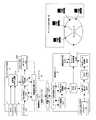
図1は、既存技術の組み合わせにより実現した動画像のネットワークサーバ蓄積システムの一例である。図1において、デジタルビデオカメラ端末装置1が、動画像伝送ネットワーク2を通して動画像蓄積サーバ装置3に接続されている。
【0023】
図1に示すシステムは、デジタルビデオカメラ端末装置1と動画像蓄積サーバ装置3の間で動画像転送を実時間で行うことに主眼を置いた構成である。この場合は、動画像蓄積サーバ装置3に蓄積されるデータが完全であることを保証しない。
【0024】
図1において、デジタルビデオカメラ端末装置1は、画像入力部11及び音声入力部12から入力される画像と音声データを、動画像符号化部13により圧縮された動画像データに符号化し、送信プロトコル処理部14に送る。
【0025】
画像入力部11はCCDやCMOSなどの撮像素子を持ったカメラデバイスであり、音声入力部12は、マイクロフォンとA/D変換デバイスにより実現される。動画像符号化部13では、MPEG−4などの動画像圧縮形式により音声と画像データを圧縮し、バイナリデータを生成する機能を有するものである。
【0026】
送信プロトコル処理部14及び、動画像蓄積サーバ装置3内部の受信プロトコル処理部32は、リアルタイム・データ転送用プロトコルであって、欠損データ再送無しに、データ転送を行う。例えば、インターネット上のプロトコルであるRTP(Real-time Transport Protocol)とUDP(User Datagram Protocol)を組み合わせることによって、これらのリアルタイム・データ転送用プロトコルとして適用できる。
【0027】
送信プロトコル処理部14は、データをパケットに変換するデータ/パケット変換部141、送信パケットバッファ142、パケット送信部143により構成される。データ/パケット変換部141は符号化されたバイナリデータを転送プロトコル用のパケット形式に変換し、送信パケットバッファ142に格納する。
【0028】
送信パケットバッファ142はFIFOの構造を持ち、パケット送信部143は送信パケットバッファ142から最古のパケットを読み出し、送受信手段15によりネットワーク2へと送信する。
【0029】
動画像蓄積サーバ装置3では、送受信手段31によってネットワーク2から送られてくるパケットを受信し、受信プロトコル処理部32によってパケットをバイナリデータに変換し、動画像蓄積部33に格納する。受信プロトコル処理部32は、パケット受信部321、受信パケットバッファ322、パケット/データ変換部323から構成されている。受信プロトコル処理部32は、送信プロトコル処理部14と対になってデータの転送を行う。
【0030】
上記の構成の場合、動画像転送ネットワーク2によってパケットの欠損が起きても、欠損をデジタルビデオカメラ端末装置1に通知する仕組みがない。また送信済みのパケットは送信パケットバッファ142から送信の都度削除されてしまうため、欠損したパケットを復元することができず、符号化した動画像のバイナリデータを完全な形で動画像データ蓄積部33に格納できる保証はない。
[動画像データの欠落がないことを保証するシステム例]
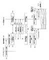
図2は、別の既存技術の組み合わせにより実現した動画像のネットワークサーバ蓄積システムの一例であり、動画像蓄積サーバ装置3に蓄積されるデータが完全であることを保証するが、実時間の転送を保証しないシステム構成である。
【0031】
図2の(A)と(B)は、それぞれ図1のシステムにおける(A)と(B)に対応しており、送信プロトコル処理部14,受信プロトコル処理部32を除いて、図1と図2は同様の構造をとる。したがって、図2において、画像入力部11,音声入力部12及び動画像データ蓄積部33は、図示省略されている。以下に図1の構成と比較しながら図2の構成の特徴について説明する。
【0032】
図1の場合と基本的に同様に動作するが、図1における欠損パケットの再送を行わない送信プロトコル処理部14及び受信プロトコル処理部32の代わりに、図2の例では再送処理を行う送信プロトコル処理部14及び受信プロトコル処理部32を用いる。再送処理を行う信頼性の高い伝送プロトコルとしては、例えばコネクション型のTCP(Transmission Control Protocol)などが適用できる。
【0033】
データ/パケット変換部141は、動画像のバイナリデータからパケットを生成し、送信パケットバッファ142に格納する。パケットにはパケットの順番を示すシーケンス番号が含まれている。パケットはパケット送信部143によって送受信手段15に送られる。同時に、再送パケットバッファ144にコピーされる。
【0034】
動画像蓄積サーバ装置3側の送受信手段31を通して受信されたパケットについて、パケット受信部321は受信したパケットのシーケンス番号を参照し、パケットの欠損を検出する。
【0035】
シーケンス番号が連番であるときはパケットの欠損がないものとして受信パケットバッファ322にパケットを格納する。また、定期的に最後に受信したシーケンス番号(受信済みシーケンス番号)を、送信プロトコル処理部14の受信通知処理部145に通知する。
【0036】
受信通知処理部145は、受信済みシーケンス番号を参照して、そのシーケンス番号とそれ以前のシーケンス番号を持つパケットを、再送パケットバッファ144から削除する。
【0037】
一方、パケット受信部321でシーケンス番号の不連続が検知された場合は、最後に連続して受信したシーケンス番号を受信通知処理部145に通知すると共に、パケットの再送要求を通知する。
【0038】
受信通知処理部145は受信済みシーケンス番号以前のパケットを再送パケットバッファ14から削除する。同時に、パケット再送部146により再送パケットバッファ144からのパケットの再送を行う。この時、パケットはパケット再送部146に送られると共に、再び再送パケットバッファ144に格納され、パケット受信部321から受信確認が通知されるまでバッファに留められる。
【0039】
以上のように、図2にシステムでは、パケットの欠損の監視手段と欠損パケットの再送機構を設けることで、動画像バイナリデータは欠落なく動画像データ蓄積部33に格納される。しかし再送処理を行っている間にも送信パケットバッファ142には送信すべきパケットが蓄積される。これにより、動画像転送ネットワーク2の帯域が十分に広くない場合は、送信パケットバッファ142のオーバフローが生じるという欠点がある。
【0040】
したがって、本発明は、上記図1,図2のシステム例における欠点を解消するネットワーク蓄積型ビデオカメラシステムを提供することを目的とする。本発明の解決原理は、実時間での動画像蓄積と欠損のない完全な動画像データを得るために、リアルタイムのデータ蓄積と欠損データの復元を分けて処理することで課題を解決するものである。
【0041】
すなわち、データの蓄積はリアルタイムに行う必要があるので、ネットワーク上でのパケット欠損を無視してパケット再送なしで転送を行う。そして、欠損したパケットの情報を送信側に通知する。
【0042】
送信側では通知される欠損したパケットをローカルに保存しておき、リアルタイム録画が終了した後に欠損パケットと受信できたパケットを用いて元データを復元するものである。
【0043】
図3は、上記本発明の解決原理を適用するネットワーク蓄積型ビデオカメラシステムの実施の形態例を示す図である。
【0044】
図3に上記本発明の解決原理を適用した動画像のネットワークサーバ蓄積システムの構成例を示す。図3におけるネットワークサーバ蓄積システムは、デジタルビデオカメラ端末装置1、動画像転送ネットワーク2、動画像蓄積サーバ装置3及び、欠損パケット転送手段4を有して構成される。
【0045】
デジタルビデオカメラ端末装置1において、画像入力部11、音声入力部12から入力した画像及び音声は、動画像符号化部13によってバイナリデータへと変換される。変換されたバイナリデータは、送信プロトコル処理部14に読み込まれる。送信プロトコル処理部14に読み込まれたバイナリデータは、データ/パケット変換部141により連番となるシーケンス番号の付されたパケットに分割される。
【0046】
分割されたパケットは、送信パケットバッファ142に順次に格納される。送信パケットバッファ142は複数のパケットを格納し、FIFO(First In First Out)の順番でデータをパケット送信部143に送出する。これと同時に、送出したパケットのコピーを欠損パケットバッファ147に格納する。
【0047】
パケット送信部143から出力されるパケットは、送受信手段15により動画像転送ネットワーク2に送り出される。動画像転送ネットワーク2は、有線公衆網や無線公衆網、無線LANやインターネットなどが想定される。したがって、送受信手段15及び動画像蓄積サーバ装置3側の送受信手段31として、適宜のネットワーク2の形態に対応する通信に必要な機能装置が選択される。
【0048】
動画像蓄積サーバ装置3において、受信したパケットはパケット受信部321によって受信される。そして、受信されたパケットは受信パケットバッファ322に格納され、次いでFIFO順に読み出されて受信パケット蓄積部34に格納される。
【0049】
同時にパケット受信部321は、パケットのシーケンス番号をチェックする。シーケンス番号に不連続が発見されない場合は、パケット受信部321は定期的に最後に受信したシーケンス番号(受信済みシーケンス番号)を、デジタルビデオカメラ端末装置1側の受信通知処理部148に通知する。
【0050】
受信通知処理部148は、受信済みシーケンス番号により、この受信済みシーケンス番号より前のパケットは、動画像蓄積サーバ装置3側で受信できていることが確認できるので、これらのパケットを欠損パケットバッファ147から削除する。
【0051】
一方、パケット受信部321がパケットシーケンス番号の不連続を発見した場合、シーケンス番号の不連続区間の最後となるシーケンス番号(欠損シーケンス番号)を受信通知処理部148に通知する。受信通知処理部148は、欠損シーケンス番号より小さい、即ち欠損シーケンス番号を含む欠損シーケンス番号以前のシーケンス番号のパケットを、欠損パケット蓄積部16にコピーすると同時に欠損パケットバッファ147から削除する。
【0052】
以上の動作によりデータ/パケット変換部141が生成したパケットは、すべて受信パケット蓄積部34もしくは欠損パケット蓄積部16に格納されたことになる。また、再送処理を行わないため受信パケット蓄積部34に対し、リアルタイム録画処理が実現可能となる。
【0053】
一方、録画終了後等、リアルタイムの動画像転送が終了した後に受信パケット蓄積部34と欠損パケット蓄積部16に格納されたパケットにより動画像データを復元処理を行う。すなわち、復元処理を開始すると、パケット/データ変換部323は、受信パケット蓄積部34と欠損パケット蓄積部16からシーケンス番号順にパケットを読み出し、バイナリデータに変換してから動画像データ蓄積部33に格納する。
【0054】
欠損パケット蓄積部16からのパケットは欠損パケット転送手段4を経由してパケット/データ変換部323により参照される。欠損パケット転送手段4としてはケーブル接続、TCPなどの信頼性の高いネットワークなどであり、データの欠損が生じない手段であればよく、リアルタイム性は問わない。
【0055】
以上の処理により最終的に動画像データ蓄積部33に欠損なく動画像データが蓄積されることが保証され、図1及び図2における課題が解消される。
【0056】
図4は、本発明を動画像ライブ配信システムに適用したときの、実施例構成図である。図5は、図4のシステムの録画開始までの処理フローである。
【0057】
本システムはネットワークカメラ端末1、メモリカード2、ネットワーク3、動画像サーバ4、ネットワーク5、クライアント再生端末6から構成される。本システムの目的は、ネットワークカメラ端末1が撮影した画像を、リアルタイムに動画像サーバ3に録画する機能とともに、クライアント再生端末6に配信する機能を提供することである。
【0058】
また動画像サーバ3上に録画した動画像を、クライアント再生端末6からの要求に応じて再配信する機能も有する。
【0059】
かかる機能実現のためにネットワークカメラ端末1は、ネットワーク2を通して動画像サーバ3に接続し、複数のクライアント再生端末6が、ネットワーク2又は別個のネットワーク5を通して、動画像サーバ3に接続される。
【0060】
図5の処理フローを参照して図4のシステムの動作を以下に説明する。先ず、ネットワークカメラ端末1において、ユーザインタフェース101からユーザの録画指示を受けると(処理工程P1)、端末制御部102は無線通信装置103を起動する(処理工程P2)。
【0061】
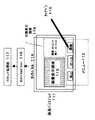
ユーザインタフェース101は、図6に実施例として示されるように液晶ディスプレイ111を有し、その上にメニュー112と画像表示領域113に撮影している画像を表示する。また、液晶ディスプレイ111に重ねて透明なタッチパネル114が配置され、タッチペン115で画面をタップすると、その位置はタッチパネルドライバ116により検知され、コマンド処理部117によってタップした位置と選択したメニューに相当する処理が実行される。
【0062】
端末制御部102は制御ソフトウエア及びマイクロプロセッサにより構成される。無線通信装置103は端末制御部102から出力する通信コマンド(ATコマンド等)を解釈し、指定された無線ゲイトウエイ302との間に無線網301上に無線経路を接続する。これにより、端末制御部102はネットワーク通信装置402を通してサーバ制御部401と通信を確立し(処理工程P3)、サーバ制御部401は端末制御部102と通信を確立する(処理工程P4)。
【0063】
ついで、端末制御部102はネットワーク2を構成する、無線網301と無線ゲイトウエイ303及び有線ネットワーク303を経由して動画像サーバ4のサーバ制御部401との間で、録画に関するネゴシエーションを行う。
【0064】
ネゴシエーションは次の手順で行われる。端末制御部102からサーバ制御部401に端末IDを送信する(処理工程P5)。サーバ制御部401で端末ID確認を行い成功すると、認証成功が端末制御部102側に通知される(処理工程P6)。認証が成功すると、端末制御部102から録画開始要求がサーバ制御部401に送られる(処理工程P7)。
【0065】
ついで、サーバ制御部401は録画するコンテンツIDを端末制御部102に送信する(処理工程P8)。コンテンツIDは、録画する動画像を識別するための番号であり、動画像データ毎に一意に設定されるものである。
【0066】
このようにして、ネゴシエーションが終了すると、次いで端末制御部102とサーバ制御部401は動画像リアルタイム送信用セッションを開始する(処理工程P9)。端末制御部102は、動画像符号化装置13と送信プロトコル処理部14を起動する(処理工程P10,P11)。一方、サーバ制御部401は受信プロトコル処理部32を起動する(処理工程P12)。
【0067】
端末制御部102から送信プロトコル処理部14に、先に処理工程P8でサーバ制御部401から通知されたコンテンツIDを送り(処理工程P13)、サーバ制御部401から受信プロトコル処理部32に同様にコンテンツIDを送り(処理工程P14)録画を開始する(処理工程P15)。
【0068】
ここで、上記カメラ11はCMOSやCCDデバイスを用いたビデオカメラであり、撮影したデジタルYUV信号を動画像符号化装置13に送る。マイクロフォン12も同様に音声をサンプリングしたPCM信号を生成し、動画像符号化装置13に送る。動画像符号化装置13は、MPEG-4やH.263などのフォーマットで動画像を符合化する装置であり、ハードウエアにより構成してもよいし、ソフトウエアで実現することも可能である。
【0069】
送信プロトコル処理部14と受信プロトコル処理部32の機能構成を図7に示す。図7において、送信プロトコル処理部14と受信プロトコル装置32の機能構成以外の部分は省略して示している。図7の左側部が送信プロトコル処理部14の機能構成であり、右側部が受信プロトコル処理部32の機能構成である。
【0070】
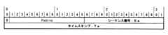
動画像符号化装置13が生成した動画像データのビットストリームは、RTPパケットジェネレータ151によりRTP(Real-time Transport Protocol)パケットに変換される。RTPパケットはヘッダ部分にパケットの送信順に振られた自然数のシーケンス番号(16bit)と、パケットの先頭バイトが送信された時間を示すタイムスタンプ(32bit)を持つ。
【0071】
RTPパケットの構造を図8に示す。タイムスタンプIは録画時刻を示し、タイムスタンプジェネレータ152により管理され、シーケンス番号はパケットの順序を示し、シーケンス番号ジェネレータ153により管理され、それぞれ適宜パケットに付加される。
【0072】
RTPパケットは送信RTPパケットバッファ154に格納される。パケットバッファ154はFIFO構造をとり、最初に書込まれたパケットが最初に読みだされる構造であり、読み出されたパケットはパケットバッファ154から消去されるように動作する。
【0073】
送信RTPパケットバッファ154は、パケット送信部155によりパケットが読み出されるときに、同時に欠損RTPパケットバッファ156にパケットのコピーを書き込む。これにより動画像サーバ3に送信されたRTPパケットのコピーは、一時的に欠損RTPパケットバッファ156にバックアップ保存される。
【0074】
パケット送信部155から受信プロトコル処理部32のパケット受信部431へ、ネットワーク2及び通信装置103,402を介してRTPパケット転送を行う。パケット受信部431は受信したRTPパケットを受信RTPパケットバッファ432に格納する。格納されたRTPパケットは、順次ハードディスク装置(HDD)403に転送保存される。
【0075】
受信RTPパケットバッファ432の出力は、同時にパケットメモリ433にも保存される。パケットメモリ433には、最新のパケットを2個だけ格納するように制御されている。シーケンスチェッカ434は、パケットバッファ433に新しいパケットが格納されると、2つのRTPパケットのヘッダ部のシーケンス番号とタイムスタンプを比較し、それらが連続していればパケット欠損なし、不連続であればパケットの欠損ありと判断する。
【0076】
受信パケットカウンタ435は受信したパケットの数をカウントしており、一定数P(P<欠損RTPパケットバッファ156に格納できるパケット数)に達すると、シーケンスチェッカ434に割り込みをかける。割り込みが発生するとシーケンスチェッカ434はパケットメモリ433を参照し、最新のRTPパケットのタイムスタンプTaとシーケンス番号Saから、図9に例示する受信通知情報を作成する。この受信通知情報が受信通知処理部157に送信されると共に、受信パケットカウンタ435が0にクリアされる。
【0077】
シーケンスチェッカ434はパケットの欠損を発見した場合、以下の処理を行う。まずパケットメモリ433に格納されている古いRTPパケット(シーケンス番号及びタイムスタンプの値が小さい方のパケット)のタイムスタンプTb, シーケンス番号Sbから、図10の受信通知情報を作成し、受信通知処理部157に送信する。
【0078】
次にパケットメモリ433中の新しいRTPパケット(シーケンス番号及びタイムスタンプの値が大きい方のパケット)のタイムスタンプTc, シーケンス番号Scから、図11の受信通知情報を作成し、受信通知処理部157に送信する。
【0079】
以上、2個の受信通知情報(図10,図11)を受信通知処理部157に送信した後、シーケンスチェッカ434は受信パケットカウンタ435をクリアする。
【0080】
受信通知処理部157は、シーケンスチェッカ434が生成する2種類の受信通知情報に応じて、次の処理を行う。
【0081】
受信通知情報の第1ワード(Word)の1Bit目が0で、受信通知情報のタイムスタンプをTd、シーケンス番号をSdとした場合の処理を図12に示す。このとき受信通知処理部157は、欠損RTPパケットバッファ156を参照して、Td、Sdのタイムスタンプとシーケンス番号を持つRTPパケットを探す。
【0082】
該当のRTPパケット及び、FIFO上で前記該当のパケットよりも先に格納されているRTPパケット分(図12のa参照)は送信成功とみなし、欠損RTPパケットバッファ156から削除する。したがって、パケット削除後の欠損RTPパケットバッファ156の内容は、図12のbに示す如くになる。
【0083】
なお、該当パケットがみつからない場合、すでに欠損RTPパケットバッファ156から消去されているとみなし処理を行わない。
【0084】
受信通知の第1ワード(Word)の1Bit目が1、受信通知情報のタイムスタンプをTe、シーケンス番号をSeとした場合の処理を図13に示す。このとき受信通知処理部157は、欠損RTPパケットバッファ156を参照して、Te、Seのタイムスタンプとシーケンス番号を持つRTPパケットを探す。
【0085】
そして、該当のRTPパケットだけを欠損RTPパケットバッファ156から削除し(図13のa参照)、FIFO上で該当のパケットよりも先に格納されているRTPパケットは受信失敗したものとみなしてカードスロット104に挿入されているメモリカード10に格納する(図13のb、図4参照)。したがって、欠損RTPパケットバッファ156の内容は、図13のcに示す如くになる。
【0086】
なお、該当パケットがみつからない場合、すでに欠損RTPパケットバッファ156から消去されているとみなし処理を行わない。
【0087】
パケットバッファ監視部158は、欠損RTPパケットバッファ156に関して、バッファオーバフローとRTPパケットのタイムアウトを監視している。
【0088】
欠損RTPパケットバッファ156のバッファ残容量が一定割合(例えば、10%)を下回った場合、オーバーフローを防ぐために、一定数(例えば、10%)のRTPパケットを読み出し、メモリカード10に格納する。また格納されているRTPパケットのタイムスタンプを監視しており、一定時間(例えば、1秒)以上古いパケットをメモリカード10に格納する。
【0089】
メモリカード10は、メモリカードスロット104によってネットワークカメラ端末1と接続している。メモリカード10は、コンテンツIDとRTPパケットを格納するものであり、例えばスマートメディア、コンパクトフラッシュ、メモリスティック(商標)などの記録デバイスが適用出来る。
【0090】
ここで、ネットワークカメラ端末1の録画時間は、ネットワーク上の蓄積媒体であるHDD404の容量及び、メモリカード10の容量に依存する。ネットワークカメラ端末1の録画時間は、ネットワーク2におけるRTPパケットの欠損率によって決定する。しかし将来におけるパケット欠損率は不明であるため、正確に残りの録画時間を算出することができない。そこで残りの録画時間を以下の処理によって算出してユーザに表示する。
【0091】
時刻TにおけるHDD404の書き込み可能容量をRs(T)(Byte)、メモリカード10の書き込み可能容量をRc(T)(Byte)とし、時刻Tまでの一定時間(例えば、10秒)における1秒あたりのRTPパケットの総送信バイト数をPs(T)(Byte/sec)、1秒あたりのRTPパケットの欠損バイト数Pl(T)(Byte/sec)とする。このとき、このパケット欠損比率で録画が行われるならば、HDD404が録画出来る時間は、下記の式により計算されるAs(T)秒である。すなわち、As(T)秒に録画不能となる。
【0092】
As(T)=Rs(T)/(Ps(T)-Pl(T)) ・・・式1
同様にメモリカード10に欠損パケットが蓄積不可能になるのは時間Ac(T)秒後である。
【0093】
Ac(T)=Rc(T)/Pl(T) ・・・式2
したがって、時刻Tにおける残り録画時間A(T)(秒)は、As(T)又は、Ac(T)のいずれか小さい方の時間であり、次式の関係で示される。
【0094】
A(T)=MIN(As(T),Ac(T)) ・・・式3
ネットワーク2におけるパケットの欠損率の変動に伴い、残り録画時間も変動する。ネットワーク2が切断された場合は、すべてのパケットをメモリカード10に蓄積するため、ローカル録画に相当する時間が残り録画時間となる。
【0095】
また、パケット欠損がまったくない場合はHDD404にすべてのパケットを格納することになるので、録画時間はメモリカード10の容量に依存しなくなる。
【0096】
端末制御部102は定期的に上記の残り録画時間を計算し、ユーザインタフェース101の液晶ディスプレイ111上の状態表示領域118にテキストもしくはグラフで表示する。
【0097】
HDD403は、受信したコンテンツIDとRTPパケットをリアルタイムで格納する。このRTPパケットは、同時にネットワーク配信装置405により、リアルタイムにネットワーク5を通してクライアント再生端末6に配信される(ライブ配信サービス)。
【0098】
ネットワーク5に接続したクライアント再生端末6は、動画像サーバ3に対して端末IDを送る。動画像サーバ3は接続認証手段404により端末IDを認証し、認証成功した場合はコネクションを確立し、RTPセッションによる動画像配信を開始する。
【0099】
ユーザインタフェース101で、ユーザがメニュー112から録画終了のメニューを選択すると、端末制御部102がサーバ制御部401に録画の終了を通知する。その後、動画像通信を行っていたRTPセッションを終了し、無線通信装置103が接続していた回線を切断する。
【0100】
欠損RTPパケットバッファ156(図7)にRTPパケットが残っている場合、パケットをメモリカード10に保存して、すべての処理を終了する。
【0101】
動画像サーバ3では、サーバ制御部401が録画終了を受信すると、受信RTPバッファ432に格納されたRTPパケットを全てHDD403に格納し、RTPセッションの終了処理を行い、録画処理を終了する。
【0102】
リアルタイム録画が終了した後、メモリカード10はネットワークカメラ1のメモリカードスロット104から取り外され、動画像サーバ3のメモリカードスロット406に接続されると、欠損パケット復元部407が起動する。
【0103】
欠損パケット復元部407はメモリカード10に格納されているコンテンツIDを参照し、同じコンテンツIDを持つRTPパケット群をHDD403から検索する。メモリカード10中のRTPパケットとタイムスタンプ及びシーケンス番号参照して、パケットの生成された順にソートを行う。
【0104】
ソートされたRTPパケットからペイロードを抽出して動画像のビットストリームに構成し直し、HDD408に格納する。このビットストリームは、動画像符号化装置104が生成したものに等しい。
【0105】
HDD408に格納されたビットストリームをクライアント再生端末6に配信する時は、配信プロトコル処理部409が、ビットストリームをRTPパケットに変換する。変換されたRTPパケットは、ライブ配信時と同様にネットワーク配信装置405から配信されるが、欠損パケットの修復後のビットストリームからRTPパケットが生成されている。このため、ネットワーク5による欠損を除き、欠損のない動画像を配信することができる。
【0106】
上記実施例において、メモリカード10を物理的に動画像サーバ3のメモリカードスロット406に接続する代わりに、録画終了後にネットワーク経由で欠損パケットを動画像サーバ3に転送するように構成しても良い。また録画終了後ではなく、録画中に欠損パケットの転送処理を行っても良い。
【0107】
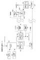
図14は、上記の録画終了後にネットワーク経由で欠損パケットを動画像サーバ3に転送する場合及び、欠損パケット5の転送処理を録画中に行う場合の実施例を説明する構成図である。
【0108】
ネットワークカメラ1は先に説明した図4の実施例の構成に加え、欠損パケット転送手段107を有する。また、動画像サーバ3は欠損パケット受信手段410とHDD411を有する。メモリカード10に蓄積されている欠損パケットは、録画中に、欠損パケット転送手段107と欠損パケット受信手段410の間でネットワーク2を介してTCP/IPなどのコネクション型転送プロトコルにより転送される。
[録画終了後に欠損パケットを転送する場合]
録画終了後、欠損パケット転送手段107と欠損パケット受信手段410によりメモリカード10の欠損パケットとコンテンツIDがHDD411に転送される。
【0109】
転送が終了した時点で、欠損パケット復元部4087起動し、HDD403とHDD411に蓄積されたパケットのうち、同じコンテンツIDのパケットをタイムスタンプとシーケンス番号を参照してソートして、RTPパケットからペイロードを抽出して動画像のビットストリームに構成し直し、HDD408に格納する。
【0110】
これにより物理的に離れた動画像サーバ3に対しても、メモリカード10の差し替えなしに動画像データの復元を行うことができる。
[録画中に欠損パケットを転送する場合]
録画中にも欠損パケット107と欠損パケット受信手段410によりメモリカード10の欠損パケットとコンテンツIDがHDD411に転送してもよい。この転送はリアルタイム性を必要とせず、またリアルタイム転送を行っているRTPセッションを圧迫しない程度の帯域で行われる。
【0111】
送信された欠損パケットは、メモリカード10から削除され、HDD411に蓄積される。メモリカード10からHDD411に転送されたパケット分だけ、先に示した式2により計算される、ネットワークカメラ端末1にローカル録画可能な残り録画時間が長くなる。録画可能な残り時間は先の式1,2,3により適宜計算されユーザインタフェース101に表示される。
【0112】
録画終了時点でメモリカード10上に欠損パケットがある場合は、メモリカード10をメモリカードスロット406に挿入して欠損パケットを復元してもよいし、ネットワーク2を経由して復元してもよい。
【0113】
(付記1)
動画像データを生成するカメラ端末装置と、
ネットワークと、
前記ネットワークを通して前記カメラ端末装置に接続される動画像蓄積サーバを有し、
前記カメラ端末装置は、生成した動画像データをパケットに変換してリアルタイムに前記動画像蓄積サーバに送信し、
前記動画像蓄積サーバは、受信されるパケットを蓄積し、受信パケットの情報を前記カメラ端末装置に通知し、
更に、前記カメラ端末装置は、通知された受信パケットの情報に基づき、送信時の欠落パケットを前記パケットのリアルタイム送信の終了後に前記動画像蓄積サーバに供給する
ことを特徴とするネットワーク蓄積型ビデオカメラシステム。
【0114】
(付記2)
動画像データを生成するカメラ端末装置と、
ネットワークと、
前記ネットワークを通して前記カメラ端末装置に接続される動画像蓄積サーバを有し、
前記カメラ端末装置は、生成した動画像データをパケットに変換してリアルタイムに前記動画像蓄積サーバに送信し、
前記動画像蓄積サーバは、受信されるパケットを蓄積し、受信パケットの情報を前記カメラ端末装置に通知し、
更に、前記カメラ端末装置は、通知された受信パケットの情報に基づき、送信時の欠落パケットを前記パケットのリアルタイム送信と並行して別回線ルートで前記動画像蓄積サーバに供給する
ことを特徴とするネットワーク蓄積型ビデオカメラシステム。
【0115】
(付記3)付記1又は2において、
前記動画像蓄積サーバは、前記パケットのリアルタイムの送信時に蓄積したパケットと、前記カメラ端末装置からリアルタイム送信の終了後に供給される欠落パケットにより前記動画像データを復元することを特徴とするネットワーク蓄積型ビデオカメラシステム。
【0116】
(付記4)付記1において、
前記カメラ端末装置に、パケットのリアルタイム送信の終了後に前記動画像蓄積サーバに供給される前記送信時の欠落パケットを記憶する記憶媒体を受けるドライブ機構を有し、
前記動画像蓄積サーバに、前記記憶媒体を受け、記憶されている前記送信時の欠落パケットを読み出すドライブ機構を有することを特徴とするネットワーク蓄積型ビデオカメラシステム。
【0117】
(付記5)付記1又は2において、
前記カメラ端末装置は、送信時に送信されるパケットを保持する記憶手段を有し、前記動画像蓄積サーバから通知される受信パケットの情報に基づき、前記動画像蓄積サーバで受信されたパケットを前記記憶手段から削除することにより、前記パケットのリアルタイム送信の終了後に前記動画像蓄積サーバに供給する欠落パケットを求めることを特徴とするネットワーク蓄積型ビデオカメラシステム。
【0118】
(付記6)付記5において、
前記カメラ端末装置は、ユーザにより撮像指示が入力されるユーザインタフェースを有し、
前記カメラ端末装置の記憶手段の記憶可能残容量と、前記動画像蓄積サーバのパケット蓄積残容量と、前記ネットワークにおける過去のデータ転送速度及びデータ欠損率とに基づいて録画可能時間を推定し、
前記推定される録画可能時間を前記ユーザインタフェースに表示することを特徴とするネットワーク蓄積型ビデオカメラシステム。
【0119】
(付記7)付記6において、
時刻Tにおける、前記カメラ端末装置の記憶手段の記憶可能残容量をRs(T)バイト、前記動画像蓄積サーバのパケット蓄積残容量をRc(T)バイト、時刻Tまでの一定時間に前記ネットワーク上で転送しようとする送信バイト数をPs(T)バイト/秒とし、更に、前記ネットワーク上の欠損データ量をPl(T)バイト/秒とする時、前記録画可能時間A(T)を
A(T)=MIN(As(T),Ac(T))
但し、As(T)=Rs(T)/(Ps(T)−Pl(T))
Ac(T)=Rc(T)/Pl(T)
により推定することを特徴とするネットワーク蓄積型ビデオカメラシステム。
【0120】
(付記8)付記3において、
さらに、前記動画像蓄積サーバにネットワークを通して、動画像再生端末が接続され、前記リアルタイム録画時には蓄積される動画像を前記動画像再生端末装置に配信し、録画終了後は復元されたデータ欠損のない動画像を配信することを特徴とするネットワーク蓄積型ビデオカメラシステム。
【0121】
【発明の効果】
上記に図面に従い説明したように、本発明により動画像及び音声をリアルタイムにネットワーク上のサーバに録画することができる。これにより、ネットワーク上のサーバにリアルタイム録画を行うためにビデオカメラの小型化と長時間録画を同時に実現することができる。
【0122】
さらに、録画時間の残りをネットワークのパケット欠損率より推定して表示するため、不確定なネットワーク状態を意識させずにユーザに録画時間の残りを通知でき、ユーザ利便性が向上する。
【0123】
また、本発明によれば、リアルタイム録画すると同時にライブ配信を行うことができる。ライブ配信のように画質クオリティよりもリアルタイム性が要求される用途のみならず、動画像のVOD(Video On Demand)配信やダウンロードサービスなどのように画像品質が重要なサービス向けのコンテンツも作成することができる。
【図面の簡単な説明】
【図1】既存技術の組み合わせにより実現した動画像のネットワークサーバ蓄積システムの一例を示す図である。
【図2】別の既存技術の組み合わせにより実現した動画像のネットワークサーバ蓄積システムの一例を示す図である。
【図3】上記本発明の解決原理を適用するネットワーク蓄積型ビデオカメラシステムの実施の形態例を示す図である。
【図4】本発明を動画像ライブ配信システムに適用したときの、実施例構成図である。
【図5】図4のシステムの処理フローを示す図である。
【図6】ユーザインタフェース101の実施例を示す図である。
【図7】送信プロトコル処理部14と受信プロトコル処理部32の機能構成を示す図である。
【図8】RTPパケットの構造を示す図である。
【図9】受信通知情報の一例(その1)を示す図である。
【図10】受信通知情報の一例(その2)を示す図である。
【図11】受信通知情報の一例(その3)を示す図である。
【図12】受信通知情報のタイムスタンプをTd、シーケンス番号をSdとした場合の送信成功時の処理を示す図である。
【図13】受信通知情報のタイムスタンプをTe、シーケンス番号をSeとした場合の送信失敗時の処理を示す図である。
【図14】録画終了後に欠損パケットを動画像サーバ3に転送する場合及び、欠損パケット5の転送処理を録画中に行う場合の実施例を説明する構成図である。
【符号の説明】
1 デジタルビデオ端末装置
2 ネットワーク
3 動画像蓄積サーバ装置
4 欠損パケット転送手段
11 画像入力部
12 音歳入力部
14 送信プロトコル処理部
15、31 送受信手段
32 受信プロトコル処理部[0001]
BACKGROUND OF THE INVENTION
The present invention relates to a network storage type video camera system, that is, a system in which video and audio data shot by a video camera are transmitted via a wired or wireless communication network and stored in a server on the network.
[0002]
Furthermore, the present invention relates to a network storage type video camera system capable of repairing missing data at the end of recording when moving image data captured by a camera is stored on a network.
[0003]
[Prior art]
With the recent progress of moving image compression technology and hardware device technology, consumer devices capable of handling digital moving image data are increasing. Some of these devices are equipped with a large-capacity hard disk (HDD) to store a large amount of moving image data and intend to record for a long time. On the other hand, there is one that has been reduced in size by using a flash memory of several tens of megabytes as a storage medium.
[0004]
However, it is difficult to reduce the size of the former because of the large-capacity HDD installed, and the latter has the problem that the recording time is short, and in order to extend the recording time, it is necessary to increase the compression rate at the expense of image quality. .
[0005]
Therefore, as a solution for both miniaturization of camera terminals and long-time recording, image storage is not performed in the recording device built in the terminal, but is stored in an external recording device connected by a communication function. Can be considered. By placing the recording device outside, the camera terminal can be downsized. Further, by making the capacity of the recording device sufficiently large, it is possible to record for a long time.
[0006]
However, in order to transfer data accurately using a network with many bit errors and low reliability like a wireless network, data is packetized and the arrival of the packet is monitored at both ends of the communication path. If there is a packet that has not arrived, it is necessary to perform retransmission processing to guarantee the identity of the data before and after transfer.
[0007]
As means for realizing this, there is an ARQ (Automatic Repeat Request) technique. ARQ is an error-free technique in which data is divided into frames and transmitted, and when there is an error frame, a request for retransmission is issued.
[0008]
However, when retransmission processing is performed using the ARQ technique, when packet loss is large, retransmission packets are frequently transferred over the network by the retransmission processing, and the bandwidth is compressed. In some cases, congestion occurs and data transfer itself becomes impossible. For this reason, the ARQ technique is not suitable for real-time data transfer.
[0009]
In particular, digital moving image data generated by a digital video camera is generated in real time and continuously. For this reason, if the completion of data transfer in real time is not guaranteed even if congestion does not occur, data that cannot be transmitted accumulates on the camera terminal, communication becomes a bottleneck, and recording itself becomes impossible.
[0010]
Conversely, if real-time transfer is guaranteed at the expense of data accuracy, lost packets need not be retransmitted. In this case, however, the data encoded by the camera cannot be transferred accurately, and the moving image data stored in the server on the network cannot be reproduced accurately. This means that the moving image recording function, which is the purpose of the digital video camera, is not fully realized.
[0011]
[Problems to be solved by the invention]
Accordingly, an object of the present invention is a network storage type video camera system that stores moving image data in a server on the network, and even if the server is on a network with low reliability, the moving image data can be obtained in real time. It is an object of the present invention to provide a network storage type video camera system capable of storing the image data and restoring the complete image data on the server.
[0012]
[Means for Solving the Problems]
The network storage type video camera system according to the present invention that solves the above-mentioned problems of the present invention includes, as a first aspect, a camera terminal device that generates moving image data,
A network and a moving image storage server connected to the camera terminal device through the network, the camera terminal device converts the generated moving image data into a packet and transmits the packet to the moving image storage server in real time; The moving image accumulation server accumulates received packets, notifies the received packet information to the camera terminal device, and further, the camera terminal device is based on the received received packet information, is missing at the time of transmission The packet is supplied to the moving image storage server after completion of the real-time transmission of the packet.
[0013]
A network storage type video camera system according to the present invention that solves the above-mentioned problems of the present invention includes, as a second aspect, a camera terminal device that generates moving image data,
A network and a moving image storage server connected to the camera terminal device through the network, the camera terminal device converts the generated moving image data into a packet and transmits the packet to the moving image storage server in real time; The moving image accumulation server accumulates received packets, notifies the received packet information to the camera terminal device, and further, the camera terminal device is based on the received received packet information, is missing at the time of transmission The packet is supplied to the moving image storage server through a separate line route in parallel with the real-time transmission of the packet.
[0014]
The network storage type video camera system according to the present invention for solving the above-described problems of the present invention, as a third aspect, in the first or second aspect, the moving image storage server stores the packet when transmitting the packet in real time. The moving image data is restored by using the received packet and the missing packet supplied after the real-time transmission is completed from the camera terminal device.
[0015]
According to a fourth aspect of the present invention, there is provided a network storage type video camera system that solves the above-mentioned problems of the present invention. Drive mechanism that receives a storage medium that stores the missing packet at the time of transmission supplied to the camera, and that receives the storage medium and stores the lost packet at the time of transmission stored in the moving image storage server It is characterized by having.
[0016]
The network storage type video camera system according to the present invention for solving the above-mentioned problems of the present invention, as a fifth aspect, in the previous first or second aspect, the camera terminal device holds a packet transmitted at the time of transmission. After the real-time transmission of the packet is completed by deleting the packet received by the moving image storage server from the storage unit based on the received packet information notified from the moving image storage server. A missing packet to be supplied to the moving image storage server is obtained.
[0017]
The network storage type video camera system according to the present invention that solves the above-mentioned problems of the present invention, as a sixth aspect, in the fifth aspect, the camera terminal device has a user interface through which an imaging instruction is input by a user. The recordable time is estimated based on the remaining storable capacity of the storage means of the camera terminal device, the remaining packet storage capacity of the moving image storage server, and the past data transfer rate and data loss rate in the network. The estimated recordable time is displayed on the user interface.
[0018]
A network storage type video camera system according to the present invention for solving the above-mentioned problems of the present invention provides, as a seventh aspect, in the sixth embodiment, the storable remaining capacity of the storage means of the camera terminal device at the time T is Rs. (T) bytes, the packet storage remaining capacity of the moving image storage server is Rc (T) bytes, and the number of transmission bytes to be transferred on the network in a certain time until time T is Ps (T) bytes / second, Further, when the amount of missing data on the network is Pl (T) bytes / second, the recordable time A (T) is set to
A (T) = MIN (As (T), Ac (T))
However, As (T) = Rs (T) / (Ps (T) -Pl (T))
Ac (T) = Rc (T) / Pl (T)
It estimates by these.
[0019]
The network storage type video camera system according to the present invention for solving the above-mentioned problems of the present invention is, as an eighth aspect, in the third aspect, a moving image playback terminal is further connected to the moving image storage server through a network. The moving image accumulated during the real-time recording is distributed to the moving image playback terminal device, and the restored moving image without data loss is distributed after the recording is completed.
[0020]
Further features of the present invention will become apparent from the embodiments described below with reference to the drawings.
[0021]
DETAILED DESCRIPTION OF THE INVENTION
Embodiments of the present invention will be described below with reference to the drawings. In the following description, components having the same or similar functions are described with the same reference numerals or symbols in the drawings.
[0022]
Here, in order to facilitate the understanding of the present invention, a conventional system example mentioned above prior to the embodiment of the invention will be described with reference to the drawings.
[System example that guarantees real-time transfer]
FIG. 1 is an example of a moving image network server storage system realized by a combination of existing technologies. In FIG. 1, a digital video
[0023]
The system shown in FIG. 1 is configured to focus on real-time transfer of moving images between the digital video
[0024]
In FIG. 1, a digital video
[0025]
The
[0026]
The transmission
[0027]
The transmission
[0028]
The
[0029]
In the moving image
[0030]
In the case of the above configuration, there is no mechanism for notifying the digital video
[Example of a system that guarantees no missing moving image data]
FIG. 2 is an example of a moving image network server storage system realized by a combination of other existing technologies, and guarantees that the data stored in the moving image
[0031]
2A and 2B correspond to (A) and (B) in the system of FIG. 1, respectively, except for the transmission
[0032]
A transmission protocol that operates basically in the same manner as in FIG. 1 but performs retransmission processing in the example of FIG. 2 instead of the transmission
[0033]
The data /
[0034]
For the packet received through the transmission / reception means 31 on the moving image
[0035]
When the sequence number is a serial number, the packet is stored in the
[0036]
The reception notification processing unit 145 refers to the received sequence number and deletes the packet having the sequence number and the previous sequence number from the retransmission packet buffer 144.
[0037]
On the other hand, when the discontinuity of sequence numbers is detected by the packet receiving unit 321, the sequence number received last is notified to the reception notification processing unit 145 and a packet retransmission request is notified.
[0038]
The reception notification processing unit 145 deletes the packet before the received sequence number from the
[0039]
As described above, in the system shown in FIG. 2, the moving image binary data is stored in the moving image
[0040]
Accordingly, an object of the present invention is to provide a network storage type video camera system that eliminates the drawbacks in the system examples of FIGS. The solution principle of the present invention solves the problem by separately processing real-time data accumulation and restoration of missing data in order to obtain real-time moving picture accumulation and complete moving picture data without missing data. is there.
[0041]
That is, since it is necessary to store data in real time, transfer is performed without packet retransmission while ignoring packet loss on the network. Then, the transmission side is notified of the information of the lost packet.
[0042]
The transmitting side stores locally the missing packet to be notified, and restores the original data using the missing packet and the received packet after the real-time recording is completed.
[0043]
FIG. 3 is a diagram showing an embodiment of a network storage type video camera system to which the solution principle of the present invention is applied.
[0044]
FIG. 3 shows a configuration example of a moving image network server storage system to which the solution principle of the present invention is applied. The network server storage system in FIG. 3 includes a digital video
[0045]
In the digital video
[0046]
The divided packets are sequentially stored in the
[0047]
The packet output from the
[0048]
In the moving image
[0049]
At the same time, the packet receiving unit 321 checks the sequence number of the packet. If no discontinuity is found in the sequence number, the packet receiving unit 321 periodically notifies the last received sequence number (received sequence number) to the reception
[0050]
The reception
[0051]
On the other hand, when the packet receiving unit 321 finds a discontinuity in the packet sequence number, it notifies the reception
[0052]
All the packets generated by the data /
[0053]
On the other hand, after the real-time moving image transfer is completed, for example, after the recording is completed, the moving image data is restored using the packets stored in the received
[0054]
Packets from the missing
[0055]
Through the above processing, it is guaranteed that the moving image data is finally accumulated in the moving image
[0056]
FIG. 4 is a block diagram of an embodiment when the present invention is applied to a moving image live distribution system. FIG. 5 is a processing flow until the start of recording in the system of FIG.
[0057]
This system includes a
[0058]
In addition, it has a function of redistributing a moving image recorded on the moving
[0059]
To realize this function, the
[0060]
The operation of the system of FIG. 4 will be described below with reference to the processing flow of FIG. First, in the
[0061]
The
[0062]
The
[0063]
Next, the
[0064]
The negotiation is performed according to the following procedure. A terminal ID is transmitted from the
[0065]
Next, the server control unit 401 transmits the content ID to be recorded to the terminal control unit 102 (processing step P8). The content ID is a number for identifying a moving image to be recorded, and is uniquely set for each moving image data.
[0066]
When the negotiation is thus completed, the
[0067]
The content ID previously notified from the server control unit 401 in the processing step P8 is sent from the
[0068]
Here, the
[0069]
The functional configurations of the transmission
[0070]
The bit stream of the moving image data generated by the moving
[0071]
The structure of the RTP packet is shown in FIG. The time stamp I indicates the recording time, and is managed by the
[0072]
The RTP packet is stored in the transmission
[0073]
The transmission
[0074]
RTP packet transfer is performed from the
[0075]
The output of the reception
[0076]
The received
[0077]
When the
[0078]
Next, the reception notification information shown in FIG. 11 is created from the time stamp Tc and sequence number Sc of the new RTP packet (packet having the larger sequence number and time stamp value) in the
[0079]
As described above, after transmitting the two pieces of reception notification information (FIGS. 10 and 11) to the reception
[0080]
The reception
[0081]
FIG. 12 shows processing when the first bit of the first word (Word) of the reception notification information is 0, the time stamp of the reception notification information is Td, and the sequence number is Sd. At this time, the reception
[0082]
The corresponding RTP packet and the RTP packet stored earlier than the corresponding packet on the FIFO (see a in FIG. 12) are regarded as successful transmissions and are deleted from the missing
[0083]
If the corresponding packet is not found, it is assumed that the packet has already been deleted from the missing
[0084]
FIG. 13 shows processing when the first bit of the first word (Word) of the reception notification is 1, the time stamp of the reception notification information is Te, and the sequence number is Se. At this time, the reception
[0085]
Then, only the corresponding RTP packet is deleted from the missing RTP packet buffer 156 (see a in FIG. 13), and the RTP packet stored before the corresponding packet on the FIFO is regarded as having failed to be received in the card slot. The data is stored in the
[0086]
If the corresponding packet is not found, it is assumed that the packet has already been deleted from the missing
[0087]
The packet
[0088]
When the remaining buffer capacity of the missing
[0089]
The
[0090]
Here, the recording time of the
[0091]
Assuming that the writable capacity of the
[0092]
As (T) = Rs (T) / (Ps (T) -Pl (T))
Similarly, the lost packet cannot be stored in the
[0093]
Ac (T) = Rc (T) / Pl (T)
Therefore, the remaining recording time A (T) (second) at time T is the smaller of As (T) or Ac (T), and is represented by the relationship of the following equation.
[0094]
A (T) = MIN (As (T), Ac (T))
As the packet loss rate in the
[0095]
If there is no packet loss, all the packets are stored in the
[0096]
The
[0097]
The
[0098]
The
[0099]
When the user selects a recording end menu from the menu 112 on the
[0100]
If there is an RTP packet remaining in the missing RTP packet buffer 156 (FIG. 7), the packet is stored in the
[0101]
In the moving
[0102]
After the real-time recording is completed, when the
[0103]
The missing
[0104]
A payload is extracted from the sorted RTP packets, reconfigured into a moving image bit stream, and stored in the
[0105]
When distributing the bit stream stored in the
[0106]
In the above embodiment, instead of physically connecting the
[0107]
FIG. 14 is a configuration diagram for explaining an embodiment in the case where the lost packet is transferred to the moving
[0108]
The
[When missing packets are transferred after recording]
After the recording is finished, the missing packet transfer unit 107 and the missing
[0109]
When the transfer is completed, the missing packet restoration unit 4087 is activated, and the packets with the same content ID among the packets stored in the
[0110]
As a result, the moving image data can be restored to the moving
[When missing packets are transferred during recording]
Even during recording, the missing packet 107 and the missing
[0111]
The transmitted lost packet is deleted from the
[0112]
If there is a missing packet on the
[0113]
(Appendix 1)
A camera terminal device for generating moving image data;
Network,
A moving image storage server connected to the camera terminal device through the network;
The camera terminal device converts the generated moving image data into a packet and transmits it to the moving image storage server in real time,
The moving image storage server stores received packets, notifies the camera terminal device of information on received packets,
Furthermore, the camera terminal device supplies a missing packet at the time of transmission to the moving image storage server after the real-time transmission of the packet based on the notified information of the received packet.
A network storage type video camera system characterized by that.
[0114]
(Appendix 2)
A camera terminal device for generating moving image data;
Network,
A moving image storage server connected to the camera terminal device through the network;
The camera terminal device converts the generated moving image data into a packet and transmits it to the moving image storage server in real time,
The moving image storage server stores received packets, notifies the camera terminal device of information on received packets,
Furthermore, the camera terminal device supplies a missing packet at the time of transmission to the moving image storage server via a separate line route in parallel with the real-time transmission of the packet based on the notified information of the received packet.
A network storage type video camera system characterized by that.
[0115]
(Appendix 3) In
The moving image storage server restores the moving image data by using a packet accumulated at the time of real-time transmission of the packet and a missing packet supplied from the camera terminal device after completion of real-time transmission. Video camera system.
[0116]
(Appendix 4) In
The camera terminal device has a drive mechanism for receiving a storage medium for storing the lost packet at the time of transmission supplied to the moving image storage server after completion of real-time transmission of the packet,
A network storage type video camera system, wherein the moving image storage server has a drive mechanism for receiving the storage medium and reading out the stored lost packets at the time of transmission.
[0117]
(Appendix 5) In
The camera terminal device has storage means for holding a packet transmitted at the time of transmission, and stores the packet received by the moving image storage server based on information of the received packet notified from the moving image storage server A network storage type video camera system characterized in that a lost packet to be supplied to the moving image storage server is obtained after the real-time transmission of the packet is completed by deleting from the means.
[0118]
(Appendix 6) In
The camera terminal device has a user interface through which an imaging instruction is input by a user,
Estimating the recordable time based on the remaining storage capacity of the storage means of the camera terminal device, the packet storage remaining capacity of the moving image storage server, the past data transfer rate and the data loss rate in the network,
A network storage type video camera system, wherein the estimated recordable time is displayed on the user interface.
[0119]
(Appendix 7) In
At time T, the storable remaining capacity of the storage means of the camera terminal device is Rs (T) bytes, the packet storage remaining capacity of the moving image storage server is Rc (T) bytes, and on the network at a certain time until time T. When the number of transmission bytes to be transferred by Ps (T) bytes / second and the amount of missing data on the network is Pl (T) bytes / second, the recordable time A (T) is set.
A (T) = MIN (As (T), Ac (T))
However, As (T) = Rs (T) / (Ps (T) -Pl (T))
Ac (T) = Rc (T) / Pl (T)
A network storage type video camera system characterized by the above.
[0120]
(Appendix 8) In
Furthermore, a moving image playback terminal is connected to the moving image storage server through a network, and the moving image stored at the time of real-time recording is distributed to the moving image playback terminal device. A network storage type video camera system characterized by distributing moving images.
[0121]
【The invention's effect】
As described above with reference to the drawings, according to the present invention, a moving image and sound can be recorded on a server on a network in real time. Thereby, in order to perform real-time recording on a server on the network, it is possible to simultaneously realize downsizing of the video camera and long time recording.
[0122]
Furthermore, since the remaining recording time is estimated and displayed from the packet loss rate of the network, the remaining recording time can be notified to the user without being aware of the indeterminate network state, and user convenience is improved.
[0123]
According to the present invention, live distribution can be performed simultaneously with real-time recording. Create content not only for applications that require real-time performance rather than image quality, such as live distribution, but also for services where video quality is important, such as VOD (Video On Demand) distribution of video and download services. Can do.
[Brief description of the drawings]
FIG. 1 is a diagram showing an example of a moving image network server storage system realized by a combination of existing technologies.
FIG. 2 is a diagram showing an example of a moving image network server storage system realized by a combination of different existing technologies.
FIG. 3 is a diagram showing an embodiment of a network storage type video camera system to which the solution principle of the present invention is applied.
FIG. 4 is a configuration diagram of an embodiment when the present invention is applied to a moving image live distribution system.
FIG. 5 is a diagram showing a processing flow of the system of FIG. 4;
6 is a diagram illustrating an example of a
7 is a diagram showing a functional configuration of a transmission
FIG. 8 is a diagram illustrating a structure of an RTP packet.
FIG. 9 is a diagram illustrating an example (part 1) of reception notification information;
FIG. 10 is a diagram illustrating an example (part 2) of reception notification information;
FIG. 11 is a diagram illustrating an example (part 3) of reception notification information;
FIG. 12 is a diagram showing processing at the time of successful transmission when the time stamp of the reception notification information is Td and the sequence number is Sd.
FIG. 13 is a diagram showing processing at the time of transmission failure when the time stamp of the reception notification information is Te and the sequence number is Se.
FIG. 14 is a configuration diagram for explaining an embodiment in the case where a lost packet is transferred to the moving
[Explanation of symbols]
1 Digital video terminal equipment
2 network
3 Moving image storage server device
4 Missing packet transfer means
11 Image input section
12 Sound age input part
14 Transmission protocol processor
15, 31 Transmission / reception means
32 Reception protocol processor
Claims (5)
Translated fromJapaneseネットワークと、
前記ネットワークを通して前記カメラ端末装置に接続される動画像蓄積サーバを有し、
前記カメラ端末装置は、生成した動画像データをパケットに変換してリアルタイムに前記動画像蓄積サーバに送信し、
前記動画像蓄積サーバは、受信されるパケットを蓄積し、受信パケットの情報を前記カメラ端末装置に通知し、
前記カメラ端末装置は、更に前記受信パケットの情報に基づき、欠落パケットを蓄積しておき、前記蓄積された送信時の欠落パケットを前記パケットのリアルタイム送信の終了後に前記動画像蓄積サーバに供給することを特徴とするネットワーク蓄積型ビデオカメラシステム。A camera terminal device for generating moving image data;
Network,
A moving image storage server connected to the camera terminal device through the network;
The camera terminal device converts the generated moving image data into a packet and transmits it to the moving image storage server in real time,
The moving image storage server stores received packets, notifies the camera terminal device of information on received packets,
The camera terminal device further accumulates missing packets based on the information of the received packets, and supplies the accumulated missing packets at the time of transmission to the moving image accumulation server after the real-time transmission of the packets. Network storage type video camera system characterized by
ネットワークと、
前記ネットワークを通して前記カメラ端末装置に接続される動画像蓄積サーバを有し、
前記カメラ端末装置は、生成した動画像データをパケットに変換してリアルタイムに前記動画像蓄積サーバに送信し、
前記動画像蓄積サーバは、受信されるパケットを蓄積し、受信パケットの情報を前記カメラ端末装置に通知し、
前記カメラ端末装置は、更に前記受信パケットの情報に基づき、欠落パケットを蓄積しておき、前記蓄積された送信時の欠落パケットを前記パケットのリアルタイム送信と並行して別回線ルートで前記動画像蓄積サーバに供給する
ことを特徴とするネットワーク蓄積型ビデオカメラシステム。A camera terminal device for generating moving image data;
Network,
A moving image storage server connected to the camera terminal device through the network;
The camera terminal device converts the generated moving image data into a packet and transmits it to the moving image storage server in real time,
The moving image storage server stores received packets, notifies the camera terminal device of information on received packets,
The camera terminal device further accumulates missing packets based on the information of the received packets, and accumulates the accumulated lost packets at the time of transmission in a separate line route in parallel with the real-time transmission of the packets. A network storage type video camera system characterized by being supplied to a server.
前記動画像蓄積サーバは、前記パケットのリアルタイムの送信時に蓄積したパケットと、前記カメラ端末装置からリアルタイム送信の終了後に供給される欠落パケットにより前記動画像データを復元することを特徴とするネットワーク蓄積型ビデオカメラシステム。In claim 1 or 2,
The moving image storage server restores the moving image data by using a packet accumulated at the time of real-time transmission of the packet and a missing packet supplied from the camera terminal device after completion of real-time transmission. Video camera system.
前記カメラ端末装置に、パケットのリアルタイム送信の終了後に前記動画像蓄積サーバに供給される前記送信時の欠落パケットを記憶する記憶媒体を受けるドライブ機構を有し、
前記動画像蓄積サーバに、前記記憶媒体を受け、記憶されている前記送信時の欠落パケットを読み出すドライブ機構を有することを特徴とするネットワーク蓄積型ビデオカメラシステム。In claim 1,
The camera terminal device has a drive mechanism for receiving a storage medium for storing the lost packet at the time of transmission supplied to the moving image storage server after completion of real-time transmission of the packet,
A network storage type video camera system, wherein the moving image storage server has a drive mechanism for receiving the storage medium and reading out the stored lost packets at the time of transmission.
前記カメラ端末装置は、送信時に送信されるパケットを保持する記憶手段を有し、前記動画像蓄積サーバから通知される受信パケットの情報に基づき、前記動画像蓄積サーバで受信されたパケットを前記記憶手段から削除することにより、前記パケットのリアルタイム送信の終了後に前記動画像蓄積サーバに供給する欠落パケットを求めることを特徴とするネットワーク蓄積型ビデオカメラシステム。In claim 1 or 2,
The camera terminal device has storage means for holding a packet transmitted at the time of transmission, and stores the packet received by the moving image storage server based on information of the received packet notified from the moving image storage server A network storage type video camera system characterized in that a lost packet to be supplied to the moving image storage server is obtained after the real-time transmission of the packet is completed by deleting from the means.
Priority Applications (2)
| Application Number | Priority Date | Filing Date | Title |
|---|---|---|---|
| JP2001204113AJP4767443B2 (en) | 2001-07-04 | 2001-07-04 | Network storage type video camera system |
| US10/033,210US7386872B2 (en) | 2001-07-04 | 2001-12-28 | Network storage type video camera system |
Applications Claiming Priority (1)
| Application Number | Priority Date | Filing Date | Title |
|---|---|---|---|
| JP2001204113AJP4767443B2 (en) | 2001-07-04 | 2001-07-04 | Network storage type video camera system |
Publications (2)
| Publication Number | Publication Date |
|---|---|
| JP2003018525A JP2003018525A (en) | 2003-01-17 |
| JP4767443B2true JP4767443B2 (en) | 2011-09-07 |
Family
ID=19040629
Family Applications (1)
| Application Number | Title | Priority Date | Filing Date |
|---|---|---|---|
| JP2001204113AExpired - Fee RelatedJP4767443B2 (en) | 2001-07-04 | 2001-07-04 | Network storage type video camera system |
Country Status (2)
| Country | Link |
|---|---|
| US (1) | US7386872B2 (en) |
| JP (1) | JP4767443B2 (en) |
Families Citing this family (50)
| Publication number | Priority date | Publication date | Assignee | Title |
|---|---|---|---|---|
| JP2001218194A (en)* | 1999-11-15 | 2001-08-10 | Canon Inc | Imaging device and control method of image distribution system, control device of imaging device, image distribution system and device, data distribution device and method |
| US20040128531A1 (en)* | 2002-12-31 | 2004-07-01 | Rotholtz Ben Aaron | Security network and infrastructure |
| DE10301457A1 (en)* | 2003-01-10 | 2004-07-29 | Vcs Video Communication Systems Ag | Recording method for video / audio data |
| DE10301455A1 (en)* | 2003-01-10 | 2004-07-29 | Vcs Video Communication Systems Ag | Process for recording video / audio data |
| JP2004266504A (en)* | 2003-02-28 | 2004-09-24 | Sony Corp | Transmission / reception system, transmission device and method, reception device and method, recording medium, and program |
| KR20040079596A (en)* | 2003-03-08 | 2004-09-16 | 주식회사 성진씨앤씨 | Network camera embedded with hub |
| JP4037411B2 (en)* | 2003-04-16 | 2008-01-23 | 富士通株式会社 | IP image transmission device |
| US7496114B2 (en) | 2003-04-16 | 2009-02-24 | Fujitsu Limited | IP image transmission apparatus |
| JP4447860B2 (en) | 2003-06-30 | 2010-04-07 | ソニー株式会社 | Network camera |
| WO2005013136A1 (en)* | 2003-08-04 | 2005-02-10 | Mitsubishi Denki Kabushiki Kaisha | Video information device and module unit |
| GB2406014B (en)* | 2003-09-10 | 2007-01-31 | Thales Uk Plc | Video system |
| US7522528B2 (en)* | 2004-11-18 | 2009-04-21 | Qvidium Technologies, Inc. | Low-latency automatic repeat request packet recovery mechanism for media streams |
| JP2006165942A (en)* | 2004-12-07 | 2006-06-22 | Sony Corp | Portable electronic equipment, information processing method and program |
| JP2006174195A (en)* | 2004-12-17 | 2006-06-29 | Hitachi Ltd | Video service system |
| JP4646668B2 (en)* | 2005-03-29 | 2011-03-09 | キヤノン株式会社 | Imaging apparatus and control method thereof |
| US8086091B2 (en) | 2005-03-31 | 2011-12-27 | Pioneer Corporation | Data recording system, data acquiring apparatus, and recording medium storing therein data acquiring apparatus control program |
| JP4396567B2 (en)* | 2005-04-15 | 2010-01-13 | ソニー株式会社 | Material recording apparatus and material recording method |
| JP4914127B2 (en)* | 2005-07-11 | 2012-04-11 | キヤノン株式会社 | Network camera device and video frame transmission method of network camera device |
| JP4712537B2 (en)* | 2005-11-18 | 2011-06-29 | パナソニック株式会社 | Network camera, network camera system, and monitoring method |
| KR20080077991A (en)* | 2005-12-19 | 2008-08-26 | 마쯔시다덴기산교 가부시키가이샤 | Content management system |
| JP5072261B2 (en)* | 2006-05-02 | 2012-11-14 | キヤノン株式会社 | Imaging apparatus, communication apparatus, system, communication method, and program |
| US7877777B2 (en)* | 2006-06-23 | 2011-01-25 | Canon Kabushiki Kaisha | Network camera apparatus and distributing method of video frames |
| KR100772194B1 (en) | 2006-07-26 | 2007-11-01 | 한국전자통신연구원 | Network-based intelligent mobile robot capable of selectively outputting images based on the movement of the subject and its method |
| JP2008042511A (en)* | 2006-08-07 | 2008-02-21 | Opt Kk | Camera system, camera apparatus and camera server |
| JP2008109364A (en)* | 2006-10-25 | 2008-05-08 | Opt Kk | Camera server system, processing method for data, and camera server |
| WO2008133589A1 (en) | 2007-04-26 | 2008-11-06 | Telefonaktiebolaget Lm Ericsson (Publ) | Precise delivering of frames for video on demand streaming |
| JP5197991B2 (en)* | 2007-05-09 | 2013-05-15 | 株式会社東芝 | Receiving device, content data transfer method |
| JP2008311831A (en)* | 2007-06-13 | 2008-12-25 | Panasonic Corp | Moving picture communication apparatus, moving picture communication system, and semiconductor integrated circuit for moving picture communication |
| US8180029B2 (en)* | 2007-06-28 | 2012-05-15 | Voxer Ip Llc | Telecommunication and multimedia management method and apparatus |
| JP4915350B2 (en)* | 2008-01-16 | 2012-04-11 | 日本電気株式会社 | Entropy encoder, video encoding device, video encoding method, and video encoding program |
| JP5383117B2 (en)* | 2008-08-21 | 2014-01-08 | キヤノン株式会社 | Recording apparatus, control method therefor, and program |
| US8300098B1 (en)* | 2008-09-16 | 2012-10-30 | Emc Corporation | Techniques for providing access to video data using a network attached storage device |
| JP5469842B2 (en)* | 2008-10-02 | 2014-04-16 | 日立コンシューマエレクトロニクス株式会社 | Content transmission device and content reception device |
| WO2010072251A1 (en)* | 2008-12-22 | 2010-07-01 | Telecom Italia S.P.A. | Measurement of data loss in a communication network |
| US20110069179A1 (en)* | 2009-09-24 | 2011-03-24 | Microsoft Corporation | Network coordinated event capture and image storage |
| ITVI20090268A1 (en)* | 2009-11-02 | 2011-05-03 | Nicola Brunelli | SYSTEM AND METHOD OF COMMUNICATION BETWEEN BUSINESS REALITY AND USERS OF AN INFORMATION NETWORK |
| KR101443237B1 (en)* | 2010-11-05 | 2014-09-23 | 텔레콤 이탈리아 소시에떼 퍼 아찌오니 | Measurement on a data flow in a communication network |
| US8972925B2 (en)* | 2011-05-27 | 2015-03-03 | Adobe Systems Incorporated | Tracking application development and distribution |
| EP2538672B1 (en)* | 2011-06-21 | 2020-08-12 | Axis AB | Method for configuring networked cameras |
| JP6180780B2 (en)* | 2013-04-22 | 2017-08-16 | 三菱電機ビルテクノサービス株式会社 | Video data transmission apparatus and video data management system |
| JP2013255265A (en)* | 2013-08-05 | 2013-12-19 | Hitachi Consumer Electronics Co Ltd | Data transmission device |
| TWI531219B (en)* | 2014-07-21 | 2016-04-21 | 元智大學 | A method and system for transferring real-time audio/video stream |
| JP6021120B2 (en) | 2014-09-29 | 2016-11-09 | インターナショナル・ビジネス・マシーンズ・コーポレーションInternational Business Machines Corporation | Method for streaming data, computer system thereof, and program for computer system |
| JP6486654B2 (en)* | 2014-11-06 | 2019-03-20 | 株式会社キッズウェイ | Image display system |
| CN105262996A (en)* | 2015-10-14 | 2016-01-20 | 深圳市飞图视讯有限公司 | Photool recording and broadcasting system |
| US20170288816A1 (en)* | 2016-03-30 | 2017-10-05 | Le Holdings (Beijing) Co., Ltd. | Method and system for compensating hls slice loss |
| CN105872613A (en)* | 2016-03-30 | 2016-08-17 | 乐视控股(北京)有限公司 | Method and system for performing HLS slice loss compensation |
| EP3497875B1 (en) | 2016-08-08 | 2023-12-13 | Record Sure Limited | A method of generating a secure record of a conversation |
| JP7085846B2 (en)* | 2018-01-15 | 2022-06-17 | 株式会社キッズウェイ | Video display system |
| CN110620889B (en)* | 2018-06-20 | 2022-04-05 | 杭州海康威视数字技术股份有限公司 | Video monitoring system, network hard disk video recorder and data transmission method |
Family Cites Families (15)
| Publication number | Priority date | Publication date | Assignee | Title |
|---|---|---|---|---|
| US5553083B1 (en)* | 1995-01-19 | 2000-05-16 | Starburst Comm Corp | Method for quickly and reliably transmitting frames of data over communications links |
| JPH10126772A (en)* | 1996-10-18 | 1998-05-15 | Chokosoku Network Computer Gijutsu Kenkyusho:Kk | Dynamic image data transfer system |
| JP3529016B2 (en)* | 1997-05-19 | 2004-05-24 | 日本電信電話株式会社 | Video playback system |
| JPH10336651A (en) | 1997-05-28 | 1998-12-18 | Matsushita Electric Ind Co Ltd | Image communication device and image communication method |
| JPH1175176A (en)* | 1997-07-02 | 1999-03-16 | Matsushita Electric Ind Co Ltd | Remote monitoring system and remote monitoring method |
| JPH11150720A (en)* | 1997-11-17 | 1999-06-02 | Matsushita Electric Ind Co Ltd | Real-time data playback device and system |
| JPH11177477A (en)* | 1997-12-16 | 1999-07-02 | Matsushita Electric Ind Co Ltd | Data communication method and system |
| JP2000059460A (en)* | 1998-08-12 | 2000-02-25 | Fuji Xerox Co Ltd | Data communication method and data communication device |
| US6587985B1 (en)* | 1998-11-30 | 2003-07-01 | Matsushita Electric Industrial Co., Ltd. | Data transmission method, data transmission apparatus, data receiving apparatus, and packet data structure |
| US6564380B1 (en)* | 1999-01-26 | 2003-05-13 | Pixelworld Networks, Inc. | System and method for sending live video on the internet |
| US6850559B1 (en)* | 1999-06-28 | 2005-02-01 | At&T Corp. | System and methods for transmitting data |
| JP2001016585A (en)* | 1999-06-30 | 2001-01-19 | Kdd Corp | Video storage / playback method and apparatus |
| US6978306B2 (en)* | 2000-08-10 | 2005-12-20 | Pts Corporation | Multi-tier video delivery network |
| JP2002199019A (en)* | 2000-12-27 | 2002-07-12 | Toshiba Corp | Communication control device, communication control method, and recording medium on which communication control program is recorded |
| JP4427912B2 (en)* | 2001-02-21 | 2010-03-10 | 日本電気株式会社 | Video packet reception decoding system and transmission system |
- 2001
- 2001-07-04JPJP2001204113Apatent/JP4767443B2/ennot_activeExpired - Fee Related
- 2001-12-28USUS10/033,210patent/US7386872B2/ennot_activeExpired - Fee Related
Also Published As
| Publication number | Publication date |
|---|---|
| JP2003018525A (en) | 2003-01-17 |
| US20030007785A1 (en) | 2003-01-09 |
| US7386872B2 (en) | 2008-06-10 |
Similar Documents
| Publication | Publication Date | Title |
|---|---|---|
| JP4767443B2 (en) | Network storage type video camera system | |
| KR100954253B1 (en) | Data transmission system, method of operation and digital media carrier | |
| US7853981B2 (en) | Multimedia streaming service system and method | |
| US9153127B2 (en) | Video transmitting apparatus, video receiving apparatus, and video transmission system | |
| CN102550020B (en) | Method of retransmission using checksum for identifying lost data packets | |
| WO2021197008A1 (en) | Audio/video communication method, terminal, server, computer device, and storage medium | |
| US7663665B2 (en) | Communication device and method for transferring video-stream data to a display device and a storage device | |
| US7319698B2 (en) | Recovery system for restoring preserved regeneration data | |
| EP1379051B1 (en) | Data sending/receiving system and method for a defect-free data transmission | |
| CN101325699A (en) | Moving image communication device and system, and semiconductor integrated circuit for moving image communication | |
| JP2009118244A (en) | Technology for transmitting data whose regeneration unit is variable | |
| JPH10126772A (en) | Dynamic image data transfer system | |
| US10694213B1 (en) | Overcoming lost or corrupted slices in video streaming | |
| KR101022078B1 (en) | Method and apparatus for facilitating streaming of video information, computer readable media and method and apparatus for processing a file comprising video information | |
| JP4242581B2 (en) | Data converter | |
| JP2010011287A (en) | Image transmission method and terminal device | |
| JP4488958B2 (en) | Video transmission system and video transmission method | |
| JP2007110395A (en) | STREAM DATA TRANSFER DEVICE, STREAM DATA TRANSFER METHOD, PROGRAM USED FOR THEM, AND RECORDING MEDIUM | |
| JP5488694B2 (en) | Remote mobile communication system, server device, and remote mobile communication system control method | |
| JP2004349743A (en) | Video stream switching system, method, and video image monitoring and video image distribution system including video stream switching system | |
| JP4266733B2 (en) | Video receiver | |
| JP3880438B2 (en) | Image communication device | |
| JP3923959B2 (en) | COMMUNICATION DEVICE, COMMUNICATION METHOD, AND RECORDING MEDIUM CONTAINING PROGRAM | |
| JP4350638B2 (en) | Video recording device | |
| JP2006279436A (en) | Multimedia communication system and data deleting method for re-transmission |
Legal Events
| Date | Code | Title | Description |
|---|---|---|---|
| A621 | Written request for application examination | Free format text:JAPANESE INTERMEDIATE CODE: A621 Effective date:20080523 | |
| A131 | Notification of reasons for refusal | Free format text:JAPANESE INTERMEDIATE CODE: A131 Effective date:20110322 | |
| A521 | Request for written amendment filed | Free format text:JAPANESE INTERMEDIATE CODE: A523 Effective date:20110520 | |
| TRDD | Decision of grant or rejection written | ||
| A01 | Written decision to grant a patent or to grant a registration (utility model) | Free format text:JAPANESE INTERMEDIATE CODE: A01 Effective date:20110614 | |
| A01 | Written decision to grant a patent or to grant a registration (utility model) | Free format text:JAPANESE INTERMEDIATE CODE: A01 | |
| A61 | First payment of annual fees (during grant procedure) | Free format text:JAPANESE INTERMEDIATE CODE: A61 Effective date:20110615 | |
| R150 | Certificate of patent or registration of utility model | Free format text:JAPANESE INTERMEDIATE CODE: R150 | |
| FPAY | Renewal fee payment (event date is renewal date of database) | Free format text:PAYMENT UNTIL: 20140624 Year of fee payment:3 | |
| LAPS | Cancellation because of no payment of annual fees |