JP4767186B2 - Rod arrangement spacer and rod arrangement method using the rod arrangement spacer - Google Patents
Rod arrangement spacer and rod arrangement method using the rod arrangement spacerDownload PDFInfo
- Publication number
- JP4767186B2 JP4767186B2JP2007014299AJP2007014299AJP4767186B2JP 4767186 B2JP4767186 B2JP 4767186B2JP 2007014299 AJP2007014299 AJP 2007014299AJP 2007014299 AJP2007014299 AJP 2007014299AJP 4767186 B2JP4767186 B2JP 4767186B2
- Authority
- JP
- Japan
- Prior art keywords
- rod
- spacer
- rod arrangement
- hollow column
- arrangement
- Prior art date
- Legal status (The legal status is an assumption and is not a legal conclusion. Google has not performed a legal analysis and makes no representation as to the accuracy of the status listed.)
- Expired - Fee Related
Links
Images


Landscapes
- Electric Cable Installation (AREA)
- Suspension Of Electric Lines Or Cables (AREA)
Description
Translated fromJapanese本発明は、各種鋼管柱やコンクリート柱等の中空柱の補強を立設した状態で行う際に、該中空柱内部に配設されるロッドの配置を容易にするロッド配置用スペーサ及び該ロッド配置用スペーサを用いたロッド配置工法に関する。 The present invention relates to a rod arrangement spacer for facilitating arrangement of a rod arranged inside a hollow column when reinforcing a hollow column such as various steel pipe columns and concrete columns upright, and the rod arrangement The present invention relates to a rod arrangement method using a spacer.
鋼管柱やコンクリート柱等の中空柱は、通常は中空柱の基端部の所定長部分が地中深く埋設されて強固に立設されおり、また中空柱上部には架線や、投光器、
トランス等が多数取り付けられるため、その立て替えは容易ではない。Hollow columns such as steel pipe columns and concrete columns are usually erected firmly with a predetermined length of the base end of the hollow column buried deep in the ground, and overhead wires, floodlights,
Since many transformers and the like are attached, it is not easy to replace the transformer.
一方、このような中空柱は、中空柱の設置環境や経年変化などにより材質等が劣化し、強度が低下する可能性のあることが指摘されることもあった。そのため、中空柱は定期的に点検され、点検の結果、補強や立て替えが行われる必要が生じることもある。 On the other hand, it has been pointed out that such a hollow column may be deteriorated in material or the like due to the installation environment of the hollow column or a secular change, and the strength may be lowered. Therefore, the hollow column is regularly inspected, and as a result of the inspection, it may be necessary to reinforce or replace the hollow column.
例えば、特許文献1では中空柱としてのコンクリート製の電柱の地際から1m程上方の電柱側面に形成された側面開口部から中空柱の内部に補強材としてのアラミドロッドを複数本、挿入したのち、複数本のアラミドロッドを治具等により均等に配置し、次にこれらアラミドロッドの隙間に例えば豆砂利や砕石を投入し、更にモルタルやコンクリートなどを順次投入し、これにより中空柱の最下端部から側面開口部付近までを補強するようにしている。
上述したように、従来のコンクリート製の電柱の補強方法では、電柱の地際から1m程上方の電柱側面に形成された側面開口部等を用いて、複数本の補強材としてのアラミドロッドを電柱の中空内に投入し、該アラミドロッドを中空内部で均等に配置し、さらにモルタル等の充填材を中空内部に充填して、電柱を補強するようにしている。 As described above, in the conventional method for reinforcing a utility pole made of concrete, aramid rods as a plurality of reinforcements are installed on a utility pole using a side opening formed on the side of a utility pole approximately 1 m above the base of the utility pole. The aramid rods are uniformly arranged inside the hollow, and a filler such as mortar is filled into the hollow to reinforce the electric pole.
このアラミドロッドの均等配置は、常に中空柱の内壁面に沿って、アラミドロッドが均等に配置されることが望まれている。例えば、コンクリート製の電柱の場合、通常は中空柱上端部から下端部側に向かって径が太くなっていく、いわゆるテーパー柱であるが、このようなテーパー柱は内部もテーパー状態であり、このようなテーパー柱であっても同様に、補強用に挿入するアラミドロッドを該ロッドの上端から下端まで中空柱のテーパー状の内壁面に沿うように配置し中空柱のより強固な補強を確保することが望まれている。 It is desired that the aramid rods be arranged uniformly along the inner wall surface of the hollow column. For example, in the case of a concrete electric pole, it is a so-called tapered pillar whose diameter increases from the upper end to the lower end of the hollow pillar, but such a tapered pillar is also tapered inside. Similarly, even in the case of such a tapered column, an aramid rod inserted for reinforcement is arranged along the tapered inner wall surface of the hollow column from the upper end to the lower end of the rod to ensure stronger reinforcement of the hollow column. It is hoped that.
そのため、アラミドロッドの配置位置(径)の異なるロッド配置用補助治具をアラミドロッドの長さ方向に複数配置することで、すなわち径の大きなロッド配置用補助治具を下部に、径の小さなロッド配置用補助治具を上部に配置することで、複数本のアラミドロッドを中空柱の長手方向及び断面方向において最適位置に配置する。 Therefore, by arranging a plurality of rod placement auxiliary jigs with different aramid rod placement positions (diameters) in the length direction of the aramid rod, that is, the rod arrangement auxiliary jig with a large diameter at the bottom and the rod with a small diameter By arranging the auxiliary jig for arrangement at the top, a plurality of aramid rods are arranged at optimum positions in the longitudinal direction and the cross-sectional direction of the hollow column.
続いて、モルタル等の充填材を中空内部に充填する。このとき、アラミドロッドが高強度・高弾性で耐久性に優れた軽量のアラミド繊維で形成されていることから、このアラミドロッドよりも比重が大である充填材を中空内部に充填すると当該アラミドロッドが不均一に浮き上がり、上述した長手方向及び断面方向における最適位置が変化し、最適性が崩れるおそれがあった。 Subsequently, a filler such as mortar is filled into the hollow interior. At this time, since the aramid rod is formed of lightweight aramid fibers having high strength, high elasticity and excellent durability, when a hollow filler is filled with a filler having a specific gravity greater than that of the aramid rod, the aramid rod However, the optimal position in the longitudinal direction and the cross-sectional direction described above may change and the optimality may be lost.
そこで、従来はアラミドロッドの下端部分に錘を付けるようにしたものもあった。しかしながら、アラミドロッドの太さ・長さ及び充填材の比重によって要求される錘の大きさは異なり、一方では錘を大きく(重く)しすぎると作業性が悪くなるという課題があり、錘の大きさ(重さ)の最適化は面倒であった。さらに、アラミドロッドの太さ・長さ及び充填材は作業現場で適宜、変更されることも多く、補強作業全体の効率低下を招来しかねなかった。 In view of this, there has conventionally been a case where a weight is attached to the lower end portion of the aramid rod. However, the required size of the weight differs depending on the thickness and length of the aramid rod and the specific gravity of the filler. On the other hand, if the weight is too large (heavy), there is a problem that workability deteriorates. The optimization of the weight (weight) was troublesome. Furthermore, the thickness and length of the aramid rod and the filler are often changed as appropriate at the work site, which may lead to a reduction in the efficiency of the entire reinforcement work.
本発明は、上記に鑑みてなされたもので、その目的とするところは、立設した状態の既設の中空柱の補強を行う際の、アラミドロッドを所定の位置への配置を容易かつ効率的に行うことを補助することを可能とするロッド配置用スペーサ及び該ロッド配置用スペーサを用いたロッド配置工法を提供することにある。 The present invention has been made in view of the above, and an object thereof is to easily and efficiently arrange an aramid rod at a predetermined position when reinforcing an existing hollow column in an upright state. It is an object of the present invention to provide a rod arrangement spacer and a rod arrangement method using the rod arrangement spacer which can be performed in an easy manner.
上記の課題を解決するために、請求項1のロッド配置用スペーサは、立設された中空柱の内部に複数本のロッドと充填材とを投入して当該中空柱を補強する際に、ロッド配置用補助治具に設けられる環状のロッド保持部で前記ロッドを保持して当該ロッドを中空柱内部で所定の間隔で配置するときのロッド配置用スペーサであって、最大外径が前記ロッド保持部の環状部分の内径よりも大である環状の本体と、この本体の外周側から内周側に貫通して設けられ、内周側を挿通されるロッドを固定する固定ネジとを備え、前記ロッド保持部に前記本体を下側から掛合させることで、この本体に固定されるロッドの浮き上がりを防止することを要旨とする。 In order to solve the above-mentioned problem, the rod arrangement spacer according to claim 1 is provided with a rod when reinforcing a plurality of rods and fillers inside the standing hollow column to reinforce the hollow column. A spacer for rod placement when the rod is held by an annular rod holding portion provided in a placement auxiliary jig and the rod is placed at a predetermined interval inside the hollow column, and the maximum outer diameter is the rod holding An annular main body that is larger than the inner diameter of the annular portion of the part, and a fixing screw that is provided penetrating from the outer peripheral side of the main body to the inner peripheral side and that fixes the rod inserted through the inner peripheral side, The gist is to prevent the rod fixed to the main body from being lifted by engaging the main body with the rod holding portion from below.
請求項1のロッド配置用スペーサによれば、ロッド配置用スペーサの環状の本体の最大外径がロッド配置用補助治具のロッド保持部の環状部分の内径よりも大であることから、充填材の投入により、ロッドが充填材との比重差から浮き上がった際に、ロッドの固定ネジで固定されたロッド配置用スペーサ本体がロッド保持部に下側から掛合し、ロッドの浮き上がりを防止することが可能となる。 According to the rod arrangement spacer of claim 1, the maximum outer diameter of the annular main body of the rod arrangement spacer is larger than the inner diameter of the annular portion of the rod holding portion of the rod arrangement auxiliary jig. When the rod is lifted due to the difference in specific gravity from the filler, the rod placement spacer body fixed with the rod fixing screw engages the rod holding part from the bottom, preventing the rod from lifting. It becomes possible.
請求項2のロッド配置用スペーサを用いたロッド配置工法は、立設された中空柱の内部に複数本のロッドと充填材とを投入して中空柱を補強する際に、ロッド配置用補助治具に設けられる環状のロッド保持部で前記ロッドを保持して当該ロッドを中空柱内部で所定の間隔で配置するときのロッド配置用スペーサを用いたロッド配置工法であって、前記ロッドの所定位置に前記ロッド保持部に掛合し得るロッド配置用スペーサを装着し固定する行程と、当該ロッド配置用スペーサを固定したロッドを中空柱内部に挿入する行程と、前記ロッド配置用補助治具を中空柱内部に挿入する行程と、前記ロッド配置用補助治具のロッド保持部にロッドに固定されたロッド配置用スペーサを掛合させる工程とを備えることを要旨とする。 In the rod arrangement method using the rod arrangement spacer according to claim 2, the rod arrangement auxiliary treatment is performed when a plurality of rods and fillers are introduced into the standing hollow column to reinforce the hollow column. A rod placement method using a rod placement spacer for holding the rod by an annular rod holding portion provided in a tool and placing the rod at a predetermined interval inside the hollow column, and a predetermined position of the rod A step of mounting and fixing a rod arrangement spacer that can be engaged with the rod holding portion, a step of inserting the rod having the rod arrangement spacer fixed therein into the hollow column, and the rod arrangement auxiliary jig as a hollow column. The gist of the present invention is to include a step of inserting the rod arrangement spacer and a rod arrangement spacer fixed to the rod on the rod holding portion of the rod arrangement auxiliary jig.
請求項2のロッド配置用スペーサを用いたロッド配置工法では、充填材の投入により、ロッドが充填材との比重差から浮き上がった際に、ロッドの固定ネジで固定されたロッド配置用スペーサ本体がロッド保持部に下側から掛合し、ロッドの浮き上がりを防止することが可能となる。 In the rod placement method using the rod placement spacer according to claim 2, when the rod is lifted from the difference in specific gravity with the filler due to the introduction of the filler, the rod placement spacer body fixed by the rod fixing screw is It is possible to engage the rod holding portion from below and prevent the rod from lifting.
請求項3のロッド配置用スペーサを用いたロッド配置工法は、前記請求項2記載のロッド配置用スペーサの最大外径が前記ロッド配置用補助治具のロッド保持部の環状部分の内径よりも大であることを要旨とする。 The rod arrangement method using the rod arrangement spacer according to
請求項3のロッド配置用スペーサを用いたロッド配置工法では、ロッド配置用スペーサの環状の本体の最大外径がロッド配置用補助治具のロッド保持部の環状部分の内径よりも大であることから、充填材の投入により、ロッドが充填材との比重差から浮き上がった際に、ロッドの固定ネジで固定されたロッド配置用スペーサ本体がロッド保持部に下側から掛合し、ロッドの浮き上がりを防止することが可能となる。 In the rod arrangement method using the rod arrangement spacer according to
本発明によれば、既設の中空柱の補強を行う際に、充填材の投入時のアラミドロッドの浮き上がりを防止し、アラミドロッドの所定の位置への配置を容易かつ効率的に行うことを補助することを可能とする。 According to the present invention, when reinforcing an existing hollow column, it is possible to prevent the aramid rod from being lifted when a filler is charged and to easily and efficiently arrange the aramid rod at a predetermined position. It is possible to do.
以下、本発明の実施の形態を図面を参照して説明する。 Hereinafter, embodiments of the present invention will be described with reference to the drawings.
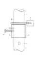
図1は、本発明に係るロッド配置用スペーサの構成を示す斜視図であり、図2は本ロッド配置用スペーサの使用状態を示す斜視図であり、さらに図3は本ロッド配置用スペーサの使用状態を示す正面図である。 FIG. 1 is a perspective view showing a configuration of a rod arrangement spacer according to the present invention, FIG. 2 is a perspective view showing a use state of the rod arrangement spacer, and FIG. 3 is a view of using the rod arrangement spacer. It is a front view which shows a state.
以下の説明において、中空柱としては各種鋼管柱(テーパーの無い鋼板柱、テーパーのあるパンザマスト(鋼板組立柱))やコンクリート柱(テーパーの有る電柱やテーパーのないコンクリート柱)が含まれるものとする。 In the following description, the hollow columns include various types of steel pipe columns (steel columns without taper, panzer mast with taper (steel assembly column)) and concrete columns (electric pole with taper or concrete column without taper). .
図1において、ロッド配置用スペーサ1の筒状体11は金属管を所定長毎に切断したもので、作業性から長さは1cm〜5cm程度が望ましい。また内径は、使用するアラミドロッドLの外径より大であれば良く、また外径は後述するようにロッド配置用補助治具3のロッド保持部33の内径よりも大であれば良い。 In FIG. 1, the
またロッド配置用スペーサ1の筒状体11の肉厚は、後述する固定ネジ13用のネジ孔15が有効長確保できれば良い。ここではロッド配置用スペーサ1の筒状体11として金属管を使用するが、樹脂製のパイプ、例えば塩ビパイプ等であっても良いのは言うまでも無い。また、角部分の面取りを行うことで、見栄えが良くなると共に、作業時における作業者の不用意な扱いによるアラミドロッドLの損傷、あるいは作業者の負傷等を防ぐことができる。 Moreover, the thickness of the
このロッド配置用スペーサ1の筒状体11の外周面には固定ネジ13用のネジ孔15が内側、中空部分に向けて穿孔され、螺刻される。 A
使用に際しては、固定ネジ13を、その先端がロッド配置用スペーサ1の筒状体11の内周面に若干、突出する程度までねじ込み、その先端面を含むように粘着テープの小片(1cm角程度)を筒状体11の内周面側から貼付する。これにより、作業中における固定ネジ13の脱落を未然に防止することが可能となる。 In use, the
次に図2と図3とを参照して、ロッド配置用スペーサ1の使用について説明する。作業手順は、各種工法によって若干の差異があるので、ここでは一般的な一例に即して説明するものとする。また、以下の作業は、電柱Pの側面に穿設された開口部や電柱頂部に開口される開口部から行われるが、以下の説明では、個々の作業については言及しない。 Next, the use of the rod arrangement spacer 1 will be described with reference to FIGS. Since the work procedure varies slightly depending on various construction methods, it will be described here with reference to a general example. Moreover, although the following operations are performed from an opening formed in the side surface of the utility pole P or an opening opened at the top of the utility pole, the following description does not refer to individual operations.
まず、下側に配置されるガイド棒41Lを電柱P内部に挿入し、このガイド棒41Lにロッド配置用補助治具3の本体フレーム31中心部分の図示していないガイド孔に挿通する。このガイド棒41Lの上端部分に連結用長ナット43を装着し、該連結用長ナット43を下側の六角穴付ボルト45でガイド棒41Lに固定する。なお連結用雄ねじ35は、電柱P側面の開口部分からロッド配置用補助治具3を操作する際に、図示しない操作治具と連結するための雄ねじ部である。 First, the
その後に、連結用長ナット43の上部に上側に配置されるガイド棒41Uを同様に連結する。この連結用長ナット43の外径は、上記本体フレーム31中心部分のガイド孔の孔径よりも大であることから、ロッド配置用補助治具3は連結用長ナット43を超えて上方に移動することは出来ない。なお、ロッド配置用補助治具3の本体フレーム31中心部分近傍には上向きのフック37と図示しない下向きのフックとが設けられ、適宜、ロッド配置用補助治具3を知り下げる際、またはロッド配置用補助治具3からカメラ等を吊り下げる際に用いられる。 Thereafter, the guide bar 41U disposed on the upper side of the connection long nut 43 is similarly connected. Since the outer diameter of the connecting long nut 43 is larger than the diameter of the guide hole in the central portion of the
次に、アラミドロッドLにロッド配置用スペーサ1を装着し、固定する。この装着に際しては、まずアラミドロッドLの所定位置に油性ペン等により印しを記入する。例えば3本のにアラミドロッドLの下端から同じ長さ(高さ)となる位置に印を付与する。この印を付与した位置にロッド配置用スペーサ1を装着し、固定ネジ13でアラミドロッドLを反対側に押し付けf、固定する(図3参照)。 Next, the rod arrangement spacer 1 is attached to the aramid rod L and fixed. At the time of mounting, a mark is first written on a predetermined position of the aramid rod L with an oil-based pen or the like. For example, a mark is given to a position where the same length (height) from the lower end of the three aramid rods L. The rod arrangement spacer 1 is attached to the position where this mark is given, and the aramid rod L is pressed to the opposite side with the fixing
続いて、ロッド配置用補助治具3を一旦、フック37に掛止したワイヤで吊り上げた後に、電柱P内部に挿入された3本のロッド配置用スペーサ1装着済みアラミドロッドLの上方から、ロッド配置用補助治具3の各ロッド保持部33の環内にアラミドロッドLを挿通させながら、降下させる。 Subsequently, the rod placement
ロッド配置用補助治具3は、アラミドロッドLに装着されたロッド配置用スペーサ1位置で下降を停止する。この状態が図2に示される。この後に、モルタル等の充填材が電柱Pの中空内部に充填されると、アラミドロッドLがその浮力Fで浮き上がり始めるが、ロッド配置用スペーサ1がロッド配置用補助治具3の各ロッド保持部33に掛止されているため、アラミドロッドLは最適位置を保持したままの状態を維持できる。 The rod placement
1…ロッド配置用スペーサ
3…ロッド配置用補助治具
11…筒状体
13…固定ネジ
15…ネジ孔
31…本体フレーム
33…ロッド保持部
35…連結用雄ねじ
37…フック
41…ガイド棒
43…連結用長ナット
45…六角穴付ボルト
L…ロッド
P…電柱DESCRIPTION OF SYMBOLS 1 ... Rod arrangement | positioning
Claims (3)
Translated fromJapanese最大外径が前記ロッド保持部の環状部分の内径よりも大である環状の本体と、
この本体の外周側から内周側に貫通して設けられ、内周側を挿通されるロッドを固定する固定ネジと
を備え、前記ロッド保持部に前記本体を下側から掛合させることで、この本体に固定されるロッドの浮き上がりを防止することを特徴とするロッド配置用スペーサ。When reinforcing a plurality of rods and fillers inside a standing hollow column to reinforce the hollow column, the rod is held by an annular rod holding portion provided in an auxiliary jig for rod arrangement. The rod arrangement spacer when arranging the rod at a predetermined interval inside the hollow column,
An annular main body having a maximum outer diameter larger than the inner diameter of the annular portion of the rod holding portion;
A fixing screw that is provided penetrating from the outer peripheral side of the main body to the inner peripheral side and that fixes the rod inserted through the inner peripheral side, and by engaging the main body from below with the rod holding portion, A rod arrangement spacer characterized by preventing the rod fixed to the main body from being lifted.
前記ロッドの所定位置に前記ロッド保持部に掛合し得るロッド配置用スペーサを装着し固定する行程と、
当該ロッド配置用スペーサを固定したロッドを中空柱内部に挿入する行程と、
前記ロッド配置用補助治具を中空柱内部に挿入する行程と、
前記ロッド配置用補助治具のロッド保持部にロッドに固定されたロッド配置用スペーサを掛合させる工程と
を備えることを特徴とするロッド配置用スペーサを用いたロッド配置工法。When reinforcing a hollow column by inserting a plurality of rods and a filler into the standing hollow column, the rod is held by an annular rod holding portion provided in a rod placement auxiliary jig. A rod placement method using a rod placement spacer when placing the rod at a predetermined interval inside the hollow column,
Mounting and fixing a rod arrangement spacer that can be engaged with the rod holding portion at a predetermined position of the rod; and
The step of inserting the rod with the rod arrangement spacer fixed therein into the hollow column;
A step of inserting the rod placement auxiliary jig into the hollow column;
And a step of engaging a rod arrangement spacer fixed to the rod with a rod holding portion of the rod arrangement auxiliary jig. A rod arrangement method using the rod arrangement spacer.
Priority Applications (1)
| Application Number | Priority Date | Filing Date | Title |
|---|---|---|---|
| JP2007014299AJP4767186B2 (en) | 2007-01-24 | 2007-01-24 | Rod arrangement spacer and rod arrangement method using the rod arrangement spacer |
Applications Claiming Priority (1)
| Application Number | Priority Date | Filing Date | Title |
|---|---|---|---|
| JP2007014299AJP4767186B2 (en) | 2007-01-24 | 2007-01-24 | Rod arrangement spacer and rod arrangement method using the rod arrangement spacer |
Publications (2)
| Publication Number | Publication Date |
|---|---|
| JP2008179988A JP2008179988A (en) | 2008-08-07 |
| JP4767186B2true JP4767186B2 (en) | 2011-09-07 |
Family
ID=39724086
Family Applications (1)
| Application Number | Title | Priority Date | Filing Date |
|---|---|---|---|
| JP2007014299AExpired - Fee RelatedJP4767186B2 (en) | 2007-01-24 | 2007-01-24 | Rod arrangement spacer and rod arrangement method using the rod arrangement spacer |
Country Status (1)
| Country | Link |
|---|---|
| JP (1) | JP4767186B2 (en) |
Families Citing this family (8)
| Publication number | Priority date | Publication date | Assignee | Title |
|---|---|---|---|---|
| JP5308738B2 (en)* | 2008-08-21 | 2013-10-09 | エヌ・ティ・ティ・インフラネット株式会社 | Hollow column reinforcement and hollow column reinforcement method using the hollow column reinforcement |
| JP4929251B2 (en)* | 2008-08-21 | 2012-05-09 | 博保 皆吉 | Reinforcing material placement jig for hollow columns |
| JP5066032B2 (en)* | 2008-08-21 | 2012-11-07 | 博保 皆吉 | Reinforcing body for hollow column and method for reinforcing hollow column using the reinforcing body |
| JP5205299B2 (en)* | 2009-02-05 | 2013-06-05 | 博保 皆吉 | Rod placement jig |
| EP2497848A4 (en) | 2009-11-06 | 2014-08-06 | Jx Nippon Mining & Metals Corp | HYBRID SILICON WAFER |
| EP2497849A4 (en) | 2009-11-06 | 2014-08-06 | Jx Nippon Mining & Metals Corp | HYBRID SILICON WAFER |
| JP2011137285A (en)* | 2009-12-25 | 2011-07-14 | Hiroyasu Minayoshi | Reinforcing body for hollow column |
| JP5684681B2 (en)* | 2011-09-20 | 2015-03-18 | エヌ・ティ・ティ・インフラネット株式会社 | Reinforcing body for steel pipe column and method for reinforcing steel pipe column using the reinforcing body |
Family Cites Families (4)
| Publication number | Priority date | Publication date | Assignee | Title |
|---|---|---|---|---|
| JPH074046A (en)* | 1993-04-02 | 1995-01-10 | Sanroode Steel Kk | Support rack for foundation beam or post bars |
| JP3421311B2 (en)* | 2000-09-08 | 2003-06-30 | 日本コンクリート工業株式会社 | Spacer for fixing reinforcing bars in concrete columns |
| JP4084247B2 (en)* | 2003-06-27 | 2008-04-30 | エヌ・ティ・ティ・インフラネット株式会社 | Reinforcing material placement jig for concrete electric pole, concrete electric pole reinforcing method, and reinforced concrete electric pole |
| JP4342458B2 (en)* | 2005-02-17 | 2009-10-14 | 博保 皆吉 | Reinforcing method for concrete utility poles |
- 2007
- 2007-01-24JPJP2007014299Apatent/JP4767186B2/ennot_activeExpired - Fee Related
Also Published As
| Publication number | Publication date |
|---|---|
| JP2008179988A (en) | 2008-08-07 |
Similar Documents
| Publication | Publication Date | Title |
|---|---|---|
| JP4767186B2 (en) | Rod arrangement spacer and rod arrangement method using the rod arrangement spacer | |
| US20130031857A1 (en) | Anchor system for securing a concrete wall panel to a supporting concrete foundation | |
| KR20170064584A (en) | Pre-fabrication method for steel reinforcement | |
| JP6871781B2 (en) | Reinforcing bar cage pile head fixing and holding structure | |
| JP5137592B2 (en) | Steel pipe pole joint structure and steel pipe pole joined thereby | |
| CN113529728A (en) | Steel reinforcement cage guiding device for cast-in-place pile construction and construction method | |
| JP4643553B2 (en) | Arrangement method and arrangement jig in hollow column of rod-shaped body | |
| CN101838986A (en) | Disassembling tool type lattice column and construction method thereof | |
| KR101621503B1 (en) | Supporter for join rebar | |
| CN210529689U (en) | Manual hole digging pile construction protection device | |
| JP5308738B2 (en) | Hollow column reinforcement and hollow column reinforcement method using the hollow column reinforcement | |
| CN215167923U (en) | Recyclable concrete embedded part | |
| JP2010261181A (en) | Pile head reinforcement jig for pre-made piles | |
| CN211340765U (en) | Device for cast-in-place pile construction | |
| JP2007332626A (en) | Jig for arranging reinforcement of steel-plate built-up column, method of reinforcing steel-plate built-up column, and reinforced steel-plate built-up column | |
| AU2006201409A1 (en) | Stump Former | |
| KR101192265B1 (en) | Phc long pile construction machine and method thereof | |
| CN110630200B (en) | Simple and easy ultra-large diameter core drilling core sample extraction device and core taking method | |
| JP2009007837A (en) | Method of hanging rod body in hollow pole, and hanging jig for use therein | |
| CN214834091U (en) | Steel reinforcement cage straightness construction structures that hangs down | |
| JP4342458B2 (en) | Reinforcing method for concrete utility poles | |
| JP5596529B2 (en) | Reinforcing bar mounting structure | |
| CN101586451A (en) | Erection device | |
| JP5150658B2 (en) | Hollow column obturator and hollow column occlusion method using the obturator | |
| CN218061453U (en) | Socket type supporting base for supporting frame body of multi-layer top plate formwork |
Legal Events
| Date | Code | Title | Description |
|---|---|---|---|
| A621 | Written request for application examination | Free format text:JAPANESE INTERMEDIATE CODE: A621 Effective date:20080814 | |
| A977 | Report on retrieval | Free format text:JAPANESE INTERMEDIATE CODE: A971007 Effective date:20110328 | |
| A01 | Written decision to grant a patent or to grant a registration (utility model) | Free format text:JAPANESE INTERMEDIATE CODE: A01 Effective date:20110531 | |
| A01 | Written decision to grant a patent or to grant a registration (utility model) | Free format text:JAPANESE INTERMEDIATE CODE: A01 | |
| A61 | First payment of annual fees (during grant procedure) | Free format text:JAPANESE INTERMEDIATE CODE: A61 Effective date:20110614 | |
| R150 | Certificate of patent (=grant) or registration of utility model | Free format text:JAPANESE INTERMEDIATE CODE: R150 | |
| FPAY | Renewal fee payment (prs date is renewal date of database) | Free format text:PAYMENT UNTIL: 20140624 Year of fee payment:3 | |
| FPAY | Renewal fee payment (prs date is renewal date of database) | Free format text:PAYMENT UNTIL: 20140624 Year of fee payment:3 | |
| S111 | Request for change of ownership or part of ownership | Free format text:JAPANESE INTERMEDIATE CODE: R313113 | |
| FPAY | Renewal fee payment (prs date is renewal date of database) | Free format text:PAYMENT UNTIL: 20140624 Year of fee payment:3 | |
| R350 | Written notification of registration of transfer | Free format text:JAPANESE INTERMEDIATE CODE: R350 | |
| R250 | Receipt of annual fees | Free format text:JAPANESE INTERMEDIATE CODE: R250 | |
| LAPS | Cancellation because of no payment of annual fees |