JP4767175B2 - Trocar device for passing surgical instruments - Google Patents
Trocar device for passing surgical instrumentsDownload PDFInfo
- Publication number
- JP4767175B2 JP4767175B2JP2006548345AJP2006548345AJP4767175B2JP 4767175 B2JP4767175 B2JP 4767175B2JP 2006548345 AJP2006548345 AJP 2006548345AJP 2006548345 AJP2006548345 AJP 2006548345AJP 4767175 B2JP4767175 B2JP 4767175B2
- Authority
- JP
- Japan
- Prior art keywords
- trocar
- instrument
- load transducer
- trocar device
- guide
- Prior art date
- Legal status (The legal status is an assumption and is not a legal conclusion. Google has not performed a legal analysis and makes no representation as to the accuracy of the status listed.)
- Expired - Fee Related
Links
- 210000001835visceraAnatomy0.000claimsabstractdescription25
- 230000007246mechanismEffects0.000claimsdescription18
- 230000003993interactionEffects0.000description13
- 238000000034methodMethods0.000description6
- 238000001356surgical procedureMethods0.000description6
- 238000005259measurementMethods0.000description5
- 230000000694effectsEffects0.000description4
- 238000002357laparoscopic surgeryMethods0.000description4
- 210000000779thoracic wallAnatomy0.000description4
- 230000005484gravityEffects0.000description3
- 210000003815abdominal wallAnatomy0.000description2
- 230000001133accelerationEffects0.000description2
- 230000009471actionEffects0.000description2
- 238000002674endoscopic surgeryMethods0.000description2
- 230000006870functionEffects0.000description2
- 230000001954sterilising effectEffects0.000description2
- 238000012549trainingMethods0.000description2
- 206010040030Sensory lossDiseases0.000description1
- 210000001015abdomenAnatomy0.000description1
- 230000003187abdominal effectEffects0.000description1
- 238000010586diagramMethods0.000description1
- 238000012976endoscopic surgical procedureMethods0.000description1
- 238000012830laparoscopic surgical procedureMethods0.000description1
- 239000000463materialSubstances0.000description1
- 238000012283microsurgical operationMethods0.000description1
- 238000012544monitoring processMethods0.000description1
- 238000011017operating methodMethods0.000description1
- 210000000056organAnatomy0.000description1
- 230000008569processEffects0.000description1
- 230000004044responseEffects0.000description1
- 229910001220stainless steelInorganic materials0.000description1
- 239000010935stainless steelSubstances0.000description1
- 238000004659sterilization and disinfectionMethods0.000description1
- 238000011179visual inspectionMethods0.000description1
Images


Classifications
- A—HUMAN NECESSITIES
- A61—MEDICAL OR VETERINARY SCIENCE; HYGIENE
- A61B—DIAGNOSIS; SURGERY; IDENTIFICATION
- A61B17/00—Surgical instruments, devices or methods
- A61B17/34—Trocars; Puncturing needles
- A61B17/3494—Trocars; Puncturing needles with safety means for protection against accidental cutting or pricking, e.g. limiting insertion depth, pressure sensors
- A—HUMAN NECESSITIES
- A61—MEDICAL OR VETERINARY SCIENCE; HYGIENE
- A61B—DIAGNOSIS; SURGERY; IDENTIFICATION
- A61B17/00—Surgical instruments, devices or methods
- A61B17/34—Trocars; Puncturing needles
- A—HUMAN NECESSITIES
- A61—MEDICAL OR VETERINARY SCIENCE; HYGIENE
- A61B—DIAGNOSIS; SURGERY; IDENTIFICATION
- A61B17/00—Surgical instruments, devices or methods
- A61B17/34—Trocars; Puncturing needles
- A61B17/3403—Needle locating or guiding means
- A—HUMAN NECESSITIES
- A61—MEDICAL OR VETERINARY SCIENCE; HYGIENE
- A61B—DIAGNOSIS; SURGERY; IDENTIFICATION
- A61B90/00—Instruments, implements or accessories specially adapted for surgery or diagnosis and not covered by any of the groups A61B1/00 - A61B50/00, e.g. for luxation treatment or for protecting wound edges
- A61B90/06—Measuring instruments not otherwise provided for
- A61B2090/064—Measuring instruments not otherwise provided for for measuring force, pressure or mechanical tension
- A—HUMAN NECESSITIES
- A61—MEDICAL OR VETERINARY SCIENCE; HYGIENE
- A61B—DIAGNOSIS; SURGERY; IDENTIFICATION
- A61B34/00—Computer-aided surgery; Manipulators or robots specially adapted for use in surgery
- A61B34/70—Manipulators specially adapted for use in surgery
- A—HUMAN NECESSITIES
- A61—MEDICAL OR VETERINARY SCIENCE; HYGIENE
- A61B—DIAGNOSIS; SURGERY; IDENTIFICATION
- A61B90/00—Instruments, implements or accessories specially adapted for surgery or diagnosis and not covered by any of the groups A61B1/00 - A61B50/00, e.g. for luxation treatment or for protecting wound edges
Landscapes
- Health & Medical Sciences (AREA)
- Surgery (AREA)
- Life Sciences & Earth Sciences (AREA)
- Medical Informatics (AREA)
- Animal Behavior & Ethology (AREA)
- Engineering & Computer Science (AREA)
- Biomedical Technology (AREA)
- Heart & Thoracic Surgery (AREA)
- Pathology (AREA)
- Molecular Biology (AREA)
- Nuclear Medicine, Radiotherapy & Molecular Imaging (AREA)
- General Health & Medical Sciences (AREA)
- Public Health (AREA)
- Veterinary Medicine (AREA)
- Oral & Maxillofacial Surgery (AREA)
- Endoscopes (AREA)
- Surgical Instruments (AREA)
- Manipulator (AREA)
Abstract
Description
Translated fromJapanese発明の分野
本発明は、手術用器具を通すためのトロカール装置に関する。The present invention relates to a trocar device for passing surgical instruments.
発明の背景
腹腔鏡手術の操作とは、トロカールを介して通過させることができるような小口径を有する小型手術用器具を用いて、外科的処置を行うものであり、この小型手術用器具には、患者の腹壁または胸壁を介して挿入される中空管がある。Background of the Invention The operation of laparoscopic surgery is to perform a surgical procedure using a small surgical instrument having a small diameter that can be passed through a trocar. There is a hollow tube that is inserted through the patient's abdominal or chest wall.
より具体的には、(a)患者の腹壁または胸壁に挿入し、外科医が目視して診察できるようにする腹腔鏡と、(b)腹腔鏡を介した視診のもとに手順を行うための器具とを挿入するのが腹腔鏡手術であり、腹部全体を開腹させる必要がない。 More specifically, (a) a laparoscope that is inserted into the patient's abdominal wall or chest wall and allows the surgeon to visually examine it, and (b) for performing procedures under visual inspection through the laparoscope It is laparoscopic surgery to insert the instrument, and there is no need to open the entire abdomen.
たとえ腹腔鏡手術はすべて手作業で行うことができても、時に自動化システムを用いて行われる。 Even though all laparoscopic surgery can be performed manually, it is sometimes performed using an automated system.
この場合、腹腔鏡手術をより正確なものとするために、外科医は手術器具を直接手で操作せずに、電気機械的なインターフェイスを介して行う。 In this case, in order to make laparoscopic surgery more accurate, the surgeon performs the electrosurgical instrument through an electromechanical interface rather than directly by hand.
このように、外科医はインターフェイスを介して、コントロールアームを動かし、自動アームを、患者に対して直接稼動するように制御し、自動アームは、たとえば、手術器具または腹腔鏡に接続される。 Thus, the surgeon moves the control arm through the interface and controls the automatic arm to operate directly on the patient, which is connected to a surgical instrument or laparoscope, for example.
しかし、これらの自動化システムを使用している間に見出される問題は、外科医は、腹腔鏡または器具により患者の内部器官に加えられた力を、直接推定することができないことである。 However, a problem found while using these automated systems is that the surgeon cannot directly estimate the force applied to the patient's internal organs by a laparoscope or instrument.
このため、外科医は、腹腔鏡の画像を表示する画面上に見られる、器官の変形を目測することにより、感覚の喪失を補う必要がある。 For this reason, the surgeon needs to compensate for the loss of sensation by measuring the deformation of the organ that is seen on the screen displaying the image of the laparoscope.
これが特に問題となるのは、非常に正確な顕微手術の動作が要求されるような、内視鏡外科手術の場合であり、この場合はすべての計測パラメータを知る必要がある。 This is particularly problematic in the case of endoscopic surgery where very precise microsurgical operation is required, in which case all measurement parameters need to be known.
現在の段階では、従来の(非内視鏡的な)用途向けとして、遠隔的に操作する制御システムがあり、操作者により患者に対して加えられる力を、外科医が制御することを可能にしている。 At the present stage, for traditional (non-endoscopic) applications, there is a remotely operated control system that allows the surgeon to control the force applied to the patient by the operator. Yes.
しかし、これらの方法は、感知される必要がある相互作用が、測定または推定が可能である、という前提に基づいている。 However, these methods are based on the premise that the interaction that needs to be sensed can be measured or estimated.
この場合、内視鏡手術において、滅菌、寸法、精度および費用の要求に見合った荷重トランスデューサを、患者の内部に取り付ける必要があるだろうと、予見することは困難である。 In this case, in endoscopic surgery, it is difficult to foresee that a load transducer that meets the requirements of sterilization, dimensions, accuracy and cost will need to be installed inside the patient.
内部にあるトランスデューサを用いずに、器具と内部器官との間の相互作用力について正確な推定を得ることは、特に有利であろう。 It would be particularly advantageous to obtain an accurate estimate of the interaction force between the instrument and the internal organ without using an internal transducer.
本発明の目的は、このような問題を、既存の自動遠隔操作システムに取り付けることができる、簡易で安価な、信頼性の高い機器装置によって解決することにある。 An object of the present invention is to solve such a problem by a simple, inexpensive and highly reliable apparatus that can be attached to an existing automatic remote control system.
発明の概要
本発明は、手術器具を通すためのトロカール装置に関し、前記器具により、患者の内部器官に対して与えられる力を測定する手段を有し、前記測定手段は、トロカール上にはめ込まれた、少なくとも1つの荷重トランスデューサの形を取り、荷重トランスデューサは、有利なことに、中央オリフィスを有するローラとして形成され、トロカールとガイドとの間に設置されていることを特徴とする。SUMMARY OF THE INVENTION The present invention relates to a trocar device for passing a surgical instrument, comprising means for measuring the force exerted by the instrument on the internal organs of a patient, the measuring means being fitted on the trocar. , In the form of at least one load transducer, which is advantageously formed as a roller having a central orifice and is located between the trocar and the guide.
ガイドは、有利なことに、縦軸(X-X)を有する管状部材の形を取り、一端において、縦軸(X-X)に対して垂直である円板を有し、前記荷重トランスデューサの前記中央オリフィスおよび前記トロカール装置に挿入されることを特徴とする。 The guide advantageously takes the form of a tubular member having a longitudinal axis (XX) and at one end has a disc perpendicular to the longitudinal axis (XX), the central orifice of the load transducer and It is inserted into the trocar device.
本発明によるトロカール装置の第1の実施態様によると、器具は自動アームにより動かされ、第2の荷重トランスデューサは、自動アームの端部と、手術器具との間に設置されることを特徴とする。 According to a first embodiment of the trocar device according to the invention, the instrument is moved by an automatic arm and the second load transducer is installed between the end of the automatic arm and the surgical instrument. .
本発明によるトロカール装置の第2の実施態様によると、器具は、ガイド上に設置されている移動機構、好ましくはローラ型の移動機構により動かされ、トロカール装置は、自動アームの端部により動かされる。 According to a second embodiment of the trocar device according to the invention, the instrument is moved by a moving mechanism, preferably a roller-type moving mechanism, installed on the guide, and the trocar device is moved by the end of the automatic arm. .
有利なことには、自動アームの動作は、全体としてインターフェイスから制御される。 Advantageously, the movement of the automatic arm is controlled as a whole from the interface.
詳細な説明
本発明はここに、添付の図面を参照して、単に説明として例を用いて説明するが、発明の範囲はこれに限るものではない。DETAILED DESCRIPTION The present invention will now be described, by way of example only, with reference to the accompanying drawings, but the scope of the invention is not limited thereto.
本発明は、腹腔鏡形式の外科手術内における用途について示しており、中でも、トロカールが用いられるところの、すべての形式による遠隔操作外科手術、または研修外科医に外科手術を紹介したり、このような手術を訓練させたりするためのあらゆるシステムに、本発明の一般原則を応用してもよいことが理解されよう。 The present invention shows its use within laparoscopic surgical procedures, including all types of telesurgery where trocars are used, or introduces surgery to a training surgeon, such as It will be appreciated that the general principles of the present invention may be applied to any system for training surgery.
図1は、インターフェイス2から遠隔的に操作する手術過程の実施において使用される、より具体的には、内視鏡外科手術において使用される自動化システム1を示す。 FIG. 1 shows an
インターフェイス2は、ディスプレイスクリーン3、および外科医が手動で動かすことのできる一対のコントロールアーム4の形を取る。 The interface 2 takes the form of a display screen 3 and a pair of control arms 4 that can be manually moved by the surgeon.
インターフェイス2は、手術を受けている患者6が載せられた手術台5とともに使用される。 The interface 2 is used with an operating table 5 on which a patient 6 undergoing surgery is placed.
手術台5は、一組の自動アーム7とともに使用され、自動アームは、腹腔鏡、カメラ、一組の鉗子、メス等とともに使用してもよいことが理解されよう。 It will be appreciated that the operating table 5 may be used with a set of
有利なことには、外科医により2本のコントロールアーム4を移動させることが、自動アーム7を移動させることにつながり、いくつかの自動アーム7を、2本のコントロールアーム4によって制御でき、インターフェイス2により、外科医が遠隔的に誘導したい自動アーム7を選択することができることが理解されよう。 Advantageously, the movement of the two control arms 4 by the surgeon leads to the movement of the
有利なことには、インターフェイス2は座席8を有しており、手術中、外科医により大きな快適さを提供し、また操作の間、長時間立ち続けることによる疲労を軽減する。 Advantageously, the interface 2 has a seat 8 that provides greater comfort to the surgeon during the procedure and reduces fatigue from standing for long periods of time during operation.
図2は、自動アームによって動く機器とともに使用される、トロカール装置の分解斜視図である。 FIG. 2 is an exploded perspective view of a trocar device used with a device that is moved by an automatic arm.
有利なことには、当技術分野において公知であるトロカール9が用いられる。すなわち、中空管状部材の形を取り、手術過程内で患者6の胸壁に挿入される。 Advantageously, a trocar 9 known in the art is used. That is, it takes the form of a hollow tubular member and is inserted into the chest wall of the patient 6 within the surgical process.
トロカール9は、当技術分野において公知であって、市販された第1の荷重トランスデューサ10、例えば、ATI Nano43(登録商標)として知られるトランスデューサに装着される。 The trocar 9 is attached to a first load transducer 10 known in the art and known as ATI Nano43®, for example.
第1の荷重トランスデューサ10は、形状において円筒形であり、好ましくはローラ状であり、中央オリフィス11を有し、その中には、移動の間は受動であり密閉されるガイド12を挿入することができる。 The first load transducer 10 is cylindrical in shape, preferably roller-shaped and has a central orifice 11 in which is inserted a
ガイド12は中空管状部材13の形を取り、一端において、管状部材13の縦軸(X-X)に対して横向きに配置されている円板14を有する。 The
有利なことには、管状部材13は、第1の荷重トランスデューサの中央オリフィス11およびトロカール9に挿入される。 Advantageously, the
ガイド12は有利なことに、滅菌材料製であり、例えばステンレス鋼などである。 The
ガイド12および第1の荷重トランスデューサ10により構成される組立部を堅固にするため、当技術分野において公知なゴムシールを、2つの部材間に追加する(図示しないが、当技術分野において公知である)。 A rubber seal known in the art is added between the two members (not shown, but known in the art) to secure the assembly comprised of the
器具15は、例えば腹腔鏡であるが、自動アーム7の端部16に接続され、ガイド12内に、1つまたは2つの自由度をもって、例えば、(X-X)に対して移動させたり、および/または(X-X)のまわりを回転させたりして、スライドさせることができる。 The instrument 15 is for example a laparoscope but is connected to the
器具15は、当技術分野において公知なあらゆる型式の手術用器具であり、トロカール9内に挿入することができる。 Instrument 15 is any type of surgical instrument known in the art and can be inserted into trocar 9.
第2の荷重トランスデューサ17は、当技術分野において公知であり、一般に市販された、例えばATI Nano43(登録商標)として知られるトランスデューサであるが、自動アーム7の端部16と、器具15との間に配置される。 The second load transducer 17 is known in the art and is a commercially available transducer, for example known as ATI Nano43®, but between the
第2の荷重トランスデューサ17における形状および機能の選択は、第1の荷重トランスデューサ11における形状および機能の選択に左右されない。
有利なことには、第2の荷重トランスデューサ17は、形状において円筒状であり、例えば中央オリフィス18からなるローラ状である。The selection of the shape and function in the second load transducer 17 does not depend on the selection of the shape and function in the first load transducer 11.
Advantageously, the second load transducer 17 is cylindrical in shape, eg a roller consisting of a central orifice 18.
器具15と、患者6の内部器官との間の相互作用力を知るために、トロカール9と、器具15との間の接続時のねじれによる力やモーメントを考慮した運動方程式に基づいて、推定器が開発されている。 In order to know the interaction force between the instrument 15 and the internal organs of the patient 6, an estimator based on an equation of motion taking into account forces and moments due to torsion during connection between the trocar 9 and the instrument 15 Has been developed.
より具体的には、ねじれ、すなわち、ボディiによりボディj上に加えられる機械的動作の任意の1点における力とモーメントを、
と表し、およびボディi上の重力場の動きを表すねじれを
と表すことにより、トロカールは静的にモデル化されることができ、当該システムは平衡状態にあると見なされる。More specifically, the forces and moments at any one point of torsion, i.e., mechanical action applied by body i on body j,
And the twist representing the motion of the gravitational field on the body i
The trocar can be modeled statically and the system is considered to be in equilibrium.
動的効果を除外することにより、器具15の平衡方程式は、以下のように定められる。
しかし、動的効果を考慮するために、トランスデューサを配置してボディの加速度を測定または推定し、測定結果を目標のモデルと併せて用いて、慣性効果を補ってもよく、この技術は当業者に周知である。 However, to account for dynamic effects, transducers may be placed to measure or estimate body acceleration, and the measurement results may be used in conjunction with the target model to compensate for inertial effects. Is well known.
このとき、ガイド12の平衡方程式は、以下のように定められる。
第1の荷重トランスデューサ10は、
を測定することができ、また第2の荷重トランスデューサ17は、
を測定することができる。The first load transducer 10 is
, And the second load transducer 17 is
Can be measured.
これら上述の2式に基づいて、器具15と、患者6の内部器官との間の相互作用力を判定することができる。 Based on these two equations, the interaction force between the instrument 15 and the internal organs of the patient 6 can be determined.
得られた数式は
となり、このとき
である。The resulting formula is
And this time
It is.
一旦
が測定されると、
が、
の測定結果と同一の基準および同一の点で表されるが、推定の実行は、当業者に自明である。Once
Is measured,
But,
Although it is represented by the same reference | standard and the same point as these measurement results, execution of estimation is obvious to those skilled in the art.
その後、重力ねじれは以下のように算出される。
この計算は、重量モデルを基礎としているものであり、当業者に自明である。 This calculation is based on a weight model and is obvious to those skilled in the art.
最終的に、すべてのねじれは、測定点
における、測定基準
で表され、この結果、器具15による、患者6の内部器官への相互作用が推定される。すなわち
となる。Eventually, all twists are measured points
In metric
As a result, the interaction of the instrument 15 with the internal organs of the patient 6 is estimated. Ie
It becomes.
この推定は、当技術分野において公知な計算機でなされ、器具により内部器官に対して加えられる力を、当技術分野において公知な形式の電気的手段を利用して、インターフェイス2上に表示するのに用いられる。 This estimation is made with a computer known in the art to display on the interface 2 the force applied by the instrument to the internal organ using electrical means of the type known in the art. Used.
また、質量や重心といった物理パラメータ、ならびに荷重トランスデューサの位置および相対方向、トロカール9に対する器具15の位置といった幾何パラメータは、モデルが特定されている場合には推測的に分かるか、または初期較正手順から得られるものであるが、このような実施は当業者にとって従来のものである。 Also, physical parameters such as mass and center of gravity, and geometric parameters such as the position and relative orientation of the load transducer, the position of the instrument 15 relative to the trocar 9, can be known speculatively if the model is specified, or from an initial calibration procedure Although obtained, such implementation is conventional to those skilled in the art.
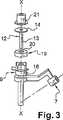
図3は、荷重トランスデューサおよび移動機構とともに用いられるトロカールの分解斜視図である。 FIG. 3 is an exploded perspective view of a trocar used with a load transducer and a moving mechanism.
図3は、本発明によるトロカール装置の代替的な説明であり、ここでは、手術用器具と、患者の内部器官との間の相互作用力を判定するために、単一の荷重トランスデューサを組み込みさえすればよい。 FIG. 3 is an alternative illustration of a trocar device according to the present invention, in which a single load transducer is incorporated to determine the interaction force between the surgical instrument and the patient's internal organs. do it.
以下の説明では、図2中のものと同一部材の参照に、同一の参照番号が付されている。 In the following description, the same reference numerals are assigned to the same members as those in FIG.
器具15により、患者6の内部器官に対して与えられる力を評価するために、管状部材13の形を取るガイド12、および円板14が、当技術分野において公知なトロカール9上に設置される。 In order to evaluate the force exerted by the instrument 15 on the internal organs of the patient 6, a
有利なことに、ガイド12は管状部材13の形を取り、一端において、管状部材13の縦軸(X-X)に対して垂直な円板14を有する。 Advantageously, the
ガイド12と、トロカール9との間には、図2のトロカールにおいてすでに用いられているものと同型の荷重トランスデューサ19が配置されている。すなわち、器具15および受動ガイド12を通すための、中央オリフィス20を有するローラ状である。 Between the
このように、荷重トランスデューサ19は当技術分野において公知であり、一般に市販され、例えば、ATI Nano43(登録商標)として知られるトランスデューサなどがある。 Thus, the load transducer 19 is known in the art and is generally commercially available, for example, a transducer known as ATI Nano43®.
ガイド12の管状部材13は、荷重トランスデューサ19の中央オリフィス20、およびトロカール9に挿入される。 The
移動機構21は、ガイド12の円板14上に設置され、器具15の(X-X)に沿って縦方向へ移動するようなことを可能にする(図3には、より明確にするための図示はしないが、これと同一型のものが図2にある)。 The moving
有利なことには、移動機構21は、当技術分野において公知であり、例えばローラ移動機構である。 Advantageously, the moving
トロカール9は、自動アーム7の端部16により、直接動かされる。 The trocar 9 is moved directly by the
これに代え、トロカール9を独立した自動化システムにより動かし、トロカール9を異なった方向に傾けられるようにしてもよい。
従って、器具15と、患者6の内部器官との間のあらゆる力が、移動機構21により荷重トランスデューサ19へと伝えられる。Alternatively, the trocar 9 may be moved by an independent automation system so that the trocar 9 can be tilted in different directions.
Accordingly, any force between the instrument 15 and the internal organs of the patient 6 is transmitted to the load transducer 19 by the moving
有利なことには、当技術分野において当業者に公知の力フィードバック制御が開発され、外部トランスデューサ19を用いて、トロカール9により発生する摩擦に妨げられずに、ボディ内の力を制御することを可能にしている。 Advantageously, a force feedback control known to those skilled in the art has been developed to use an external transducer 19 to control the force in the body without being disturbed by the friction generated by the trocar 9. It is possible.
より正確に述べれば、図2のトロカールと同様、器具15と内部器官6との間の相互作用力を推定するために、ねじれ、すなわち、ボディiによりボディj上に与えられる機械的動作の、任意の1点における力とモーメントを、
と表し、ボディi上の重力場の動きを表すねじれを
と表すことにより、トロカールは静的にモデル化されることができ、当該システムは平衡状態にあると見なされる。More precisely, similar to the trocar of FIG. 2, in order to estimate the interaction force between the instrument 15 and the internal organ 6, a twist, i.e. of the mechanical movement imparted on the body j by the body i, The force and moment at any one point
And the twist representing the movement of the gravitational field on the body i
The trocar can be modeled statically and the system is considered to be in equilibrium.
これは、手術において使用される速度において、加速度における慣性の効果は無視してよいと見なされてもよいためである。 This is because, at the speed used in surgery, the effect of inertia on acceleration may be considered negligible.
トロカール9の各種の力をモデル化し推定するために、器具15、移動機構21およびガイド12の平衡方程式が、以下のように定められる。 In order to model and estimate the various forces of the trocar 9, the balance equations of the instrument 15, the moving
器具15の平衡方程式
移動機構21の平衡方程式
ガイド12の平衡方程式
注目すべきなのは、
は、荷重トランスデューサ19により測定される力である。It should be noted that
Is the force measured by the load transducer 19.
器具15と、患者16の内部器官との間の相互作用力が推定されることになる。すなわち
となる。The interaction force between the instrument 15 and the internal organs of the patient 16 will be estimated. Ie
It becomes.
前記3つの方程式を組み合わせることにより、下記の数式が得られる。
これにより、最終的に求められるのは、
As a result, the final requirement is
従って、トランスデューサ19により測定される力は、器具15と、患者6の内部器官との間の内力であるが、器具15、受動ガイド12および移動機構21で構成される組立部の重量を除く。 Accordingly, the force measured by the transducer 19 is an internal force between the instrument 15 and the internal organs of the patient 6, but excludes the weight of the assembly composed of the instrument 15, the
さらに、注目すべきなのは、受動ガイド12と器具15との間の摩擦、および胸壁とトロカール9との間の相互作用は、測定値には含まれない。 Furthermore, it should be noted that the friction between the
従って、器具15と、患者6の内部器官との間の相互作用を推定するために、荷重トランスデューサ19により発生するねじれ、すなわち
が、最初に測定されなければならない。Thus, to estimate the interaction between the instrument 15 and the internal organs of the patient 6, the twist generated by the load transducer 19, i.e.
Must be measured first.
その後、重力場のねじれ、すなわち
を計算する必要がある。Then the twist of the gravitational field, ie
Need to be calculated.
ここで、器具15と、患者6の内部器官との間の相互作用は、以下の式により推定することができる。
重力ねじれを計算するために、いくつかの方法が一般に用いられている。 Several methods are commonly used to calculate gravity torsion.
− 器具15、移動機構21およびガイド12の重量モデル(質量および重心の位置)のいずれも完全に分かっている。
この場合、重力ねじれの計算は、自動アーム16上に配置され、トロカール9に直接接続されている位置センサにより求められた、トロカール9の方向の測定値に基づいて、および移動機構21上に設置された位置センサにより求められた、ガイド12に対する器具15の位置の測定値からなされるが、この測定手段は、当業者に自明である。-All of the weight models (mass and the position of the center of gravity) of the instrument 15, the moving
In this case, the calculation of the gravitational torsion is installed on the moving
− またはモデルを基礎とする計算に必要である、1以上のパラメータが分かっていない。
この場合、操作に先立って較正が行われる。これを受けて、当該システムは、移動機構21および自動アーム7の端部16を利用して、異なった幾何的配置に置かれ、このとき器具15が患者6の内部器官に確実に接触しないようにする。-Or one or more parameters that are required for model-based calculations are not known.
In this case, calibration is performed prior to operation. In response, the system is placed in a different geometric arrangement utilizing the moving
ここで、操作手順に従って、対応表を作るか、または重量モデルのパラメータを識別することが可能であり、これは当業者に周知である。 Here, according to the operating procedure, it is possible to create a correspondence table or identify the parameters of the weight model, which is well known to those skilled in the art.
また、荷重トランスデューサ19に代えて、器具15に関する基準で、および荷重トランスデューサ19に関する点に代えて、器具15の端部に対応する点において、器具15により患者6の内部器官に与えられる力のねじれを表すことが可能である。
この場合、トランスデューサ19に関する器具の相対位置を知るのに十分であり、これは当業者にとっては従来のものである手段によって計算することができる。Also, a twist of the force applied by the instrument 15 to the internal organ of the patient 6 at the point corresponding to the end of the instrument 15 in place of the load transducer 19 on the basis of the instrument 15 and instead of the point on the load transducer 19. Can be expressed.
In this case, it is sufficient to know the relative position of the instrument with respect to the transducer 19, which can be calculated by means conventional to those skilled in the art.
このように、手術器具15と、患者6の内部器官との間の相互作用力を、トロカール9の外側に配置された荷重トランスデューサ(10、17、19)から判定することができる。 In this way, the interaction force between the surgical instrument 15 and the internal organs of the patient 6 can be determined from the load transducers (10, 17, 19) arranged outside the trocar 9.
手術器具15と、患者6の内部器官との間の相互作用力の推定は、荷重トランスデューサ(10、17、19)により測定されたねじれに基づいてなされ、当技術分野において公知な計算機を用いて、器具15により患者6の内部器官に対して与えられる力を、インターフェイス2上に即時に表示する。 The estimation of the interaction force between the surgical instrument 15 and the internal organs of the patient 6 is made based on the torsion measured by the load transducer (10, 17, 19) and using a computer known in the art. The force applied to the internal organs of the patient 6 by the instrument 15 is immediately displayed on the interface 2.
有利なことには、外科医は、インターフェイス2より、超過することができない、患者6の内部器官に対して加えられるべき最大力を判定することができる。 Advantageously, the surgeon can determine from the interface 2 the maximum force that should be applied to the internal organs of the patient 6 that cannot be exceeded.
この内部器官6に加えられる力の限界を用いることにより、より高い力による、強力で制御不能な動作を、患者6の内部器官に確実に与えないようにする。 By using this limit of force applied to the internal organ 6, it is ensured that a powerful and uncontrollable action due to higher forces is not applied to the internal organ of the patient 6.
有利なことには、インターフェイス2は、器具により加えられる力を監視する手段、および/または、器具により作り出された力を、コントロールアーム4を用いて、外科医に還元する手段を有する。 Advantageously, the interface 2 has means for monitoring the force applied by the instrument and / or means for reducing the force created by the instrument to the surgeon using the control arm 4.
Claims (12)
Translated fromJapanese前記測定手段が、少なくとも1つの荷重トランスデューサ(10、19)の形を取り、
前記荷重トランスデューサ(10、19)が、前記トロカール(9)と、ガイド(12)との間に配置されている
ことを特徴とする、前記手術器具(15)を通すためのトロカール装置(9)。The surgical instrument (15),viewed including the patient (6) measuring means for measuring the force applied to the internal organs(10,17,19),
Said measuring means takes the form of at least one load transducer (10, 19);
Trocar device (9) for passing the surgical instrument (15), characterized in that theload transducer (10, 19) is arranged between the trocar (9) and a guide (12 ) .
Applications Claiming Priority (3)
| Application Number | Priority Date | Filing Date | Title |
|---|---|---|---|
| EP04290028.2 | 2004-01-07 | ||
| EP04290028AEP1552793B1 (en) | 2004-01-07 | 2004-01-07 | Trokar für die Durchführung eines chirurgischen Instrumentes |
| PCT/FR2005/000042WO2005067804A1 (en) | 2004-01-07 | 2005-01-07 | Trocar device for passing a surgical tool |
Publications (3)
| Publication Number | Publication Date |
|---|---|
| JP2007528238A JP2007528238A (en) | 2007-10-11 |
| JP2007528238A5 JP2007528238A5 (en) | 2008-02-28 |
| JP4767175B2true JP4767175B2 (en) | 2011-09-07 |
Family
ID=34586007
Family Applications (1)
| Application Number | Title | Priority Date | Filing Date |
|---|---|---|---|
| JP2006548345AExpired - Fee RelatedJP4767175B2 (en) | 2004-01-07 | 2005-01-07 | Trocar device for passing surgical instruments |
Country Status (8)
| Country | Link |
|---|---|
| US (1) | US20110178477A1 (en) |
| EP (1) | EP1552793B1 (en) |
| JP (1) | JP4767175B2 (en) |
| KR (1) | KR20070037565A (en) |
| AT (1) | ATE355023T1 (en) |
| CA (1) | CA2552589A1 (en) |
| DE (1) | DE602004004995T2 (en) |
| WO (1) | WO2005067804A1 (en) |
Families Citing this family (18)
| Publication number | Priority date | Publication date | Assignee | Title |
|---|---|---|---|---|
| WO2007147232A1 (en)* | 2006-06-19 | 2007-12-27 | Robarts Research Institute | Apparatus for guiding a medical tool |
| JP5464426B2 (en)* | 2010-01-19 | 2014-04-09 | 独立行政法人産業技術総合研究所 | Puncture needle insertion device |
| KR101876386B1 (en)* | 2011-12-29 | 2018-07-11 | 삼성전자주식회사 | Medical robotic system and control method for thereof |
| DE102013100605A1 (en)* | 2013-01-22 | 2014-07-24 | Rg Mechatronics Gmbh | Robotic system and method for controlling a robotic system for minimally invasive surgery |
| US9817019B2 (en) | 2013-11-13 | 2017-11-14 | Intuitive Surgical Operations, Inc. | Integrated fiber bragg grating accelerometer in a surgical instrument |
| US10470796B2 (en)* | 2014-07-29 | 2019-11-12 | Intuitive Surgical Operations, Inc. | Cannula with sensors to measure patient bodywall forces |
| WO2016064632A1 (en)* | 2014-10-24 | 2016-04-28 | Covidien Lp | Sensorizing robotic surgical system access ports |
| CN104586479B (en)* | 2015-01-07 | 2016-11-09 | 东南大学 | A puncture device for laparoscopic surgery with automatic alarm |
| AU2016247965A1 (en)* | 2015-04-15 | 2017-09-14 | Covidien Lp | Methods for exchanging instruments using a surgical port assembly |
| CN105079896B (en)* | 2015-10-12 | 2017-03-22 | 徐彬 | Follow-up pericardial fluid suction device |
| DE102016205085B3 (en) | 2016-03-29 | 2017-03-30 | Kuka Roboter Gmbh | Medical manipulator and method for controlling a medical manipulator |
| US10624671B2 (en)* | 2016-12-21 | 2020-04-21 | Ethicon Llc | Trocar attachment devices and methods |
| US11478316B2 (en) | 2017-09-20 | 2022-10-25 | Shanghai Microport Medbot (Group) Co., Ltd. | Surgical robot system |
| KR102161142B1 (en)* | 2018-09-14 | 2020-09-29 | (주)미래컴퍼니 | Operation trocar |
| US12419713B2 (en) | 2018-11-15 | 2025-09-23 | Intuitive Surgical Operations, Inc. | Surgical instrument with sensor aligned cable guide |
| US12239393B2 (en) | 2020-05-18 | 2025-03-04 | Intuitive Surgical Operations, Inc. | Hard stop that produces a reactive moment upon engagement for cantilever-based force sensing |
| US20220022915A1 (en)* | 2020-07-22 | 2022-01-27 | Covidien Lp | Trocar system with force sensing |
| JP2022142902A (en)* | 2021-03-17 | 2022-10-03 | ソニーグループ株式会社 | Force measuring device and force measuring method, surgical device, and surgical system |
Citations (6)
| Publication number | Priority date | Publication date | Assignee | Title |
|---|---|---|---|---|
| JPH05154094A (en)* | 1991-12-03 | 1993-06-22 | Olympus Optical Co Ltd | Pneumoperitoneum apparatus |
| JPH05337127A (en)* | 1992-06-04 | 1993-12-21 | Olympus Optical Co Ltd | Tracheal puncturing apparatus |
| JPH0751281A (en)* | 1993-05-12 | 1995-02-28 | Ethicon Inc | Dull-end ultrasonic cannula needle |
| WO2001070117A2 (en)* | 2000-03-23 | 2001-09-27 | Microheart, Inc. | Pressure sensor for therapeutic delivery device and method |
| EP1285634A1 (en)* | 2001-08-21 | 2003-02-26 | Computer Motion, Inc. | Robotically controlled surgical instrument with visual force-feedback |
| JP2004081852A (en)* | 2002-08-07 | 2004-03-18 | National Institute Of Advanced Industrial & Technology | Needle-punching device and method for detecting operation state of needle of the needle-punching device |
Family Cites Families (1)
| Publication number | Priority date | Publication date | Assignee | Title |
|---|---|---|---|---|
| US5259385A (en)* | 1991-12-23 | 1993-11-09 | Advanced Cardiovascular Systems, Inc. | Apparatus for the cannulation of blood vessels |
- 2004
- 2004-01-07DEDE602004004995Tpatent/DE602004004995T2/ennot_activeExpired - Lifetime
- 2004-01-07ATAT04290028Tpatent/ATE355023T1/ennot_activeIP Right Cessation
- 2004-01-07EPEP04290028Apatent/EP1552793B1/ennot_activeExpired - Lifetime
- 2005
- 2005-01-07KRKR1020067015893Apatent/KR20070037565A/ennot_activeCeased
- 2005-01-07CACA002552589Apatent/CA2552589A1/ennot_activeAbandoned
- 2005-01-07WOPCT/FR2005/000042patent/WO2005067804A1/enactiveApplication Filing
- 2005-01-07USUS10/585,412patent/US20110178477A1/ennot_activeAbandoned
- 2005-01-07JPJP2006548345Apatent/JP4767175B2/ennot_activeExpired - Fee Related
Patent Citations (6)
| Publication number | Priority date | Publication date | Assignee | Title |
|---|---|---|---|---|
| JPH05154094A (en)* | 1991-12-03 | 1993-06-22 | Olympus Optical Co Ltd | Pneumoperitoneum apparatus |
| JPH05337127A (en)* | 1992-06-04 | 1993-12-21 | Olympus Optical Co Ltd | Tracheal puncturing apparatus |
| JPH0751281A (en)* | 1993-05-12 | 1995-02-28 | Ethicon Inc | Dull-end ultrasonic cannula needle |
| WO2001070117A2 (en)* | 2000-03-23 | 2001-09-27 | Microheart, Inc. | Pressure sensor for therapeutic delivery device and method |
| EP1285634A1 (en)* | 2001-08-21 | 2003-02-26 | Computer Motion, Inc. | Robotically controlled surgical instrument with visual force-feedback |
| JP2004081852A (en)* | 2002-08-07 | 2004-03-18 | National Institute Of Advanced Industrial & Technology | Needle-punching device and method for detecting operation state of needle of the needle-punching device |
Also Published As
| Publication number | Publication date |
|---|---|
| EP1552793B1 (en) | 2007-02-28 |
| DE602004004995D1 (en) | 2007-04-12 |
| ATE355023T1 (en) | 2006-03-15 |
| JP2007528238A (en) | 2007-10-11 |
| US20110178477A1 (en) | 2011-07-21 |
| KR20070037565A (en) | 2007-04-05 |
| CA2552589A1 (en) | 2005-07-28 |
| WO2005067804A1 (en) | 2005-07-28 |
| DE602004004995T2 (en) | 2007-11-22 |
| EP1552793A1 (en) | 2005-07-13 |
Similar Documents
| Publication | Publication Date | Title |
|---|---|---|
| JP4767175B2 (en) | Trocar device for passing surgical instruments | |
| RU2741469C1 (en) | Robotic surgical system | |
| JP5754820B2 (en) | Surgical robot | |
| US10743949B2 (en) | Methods, systems, and devices relating to force control surgical systems | |
| CN107961078B (en) | Surgical robot system and surgical instrument thereof | |
| US8347738B2 (en) | Sensors and control for an interventional catheter | |
| Tholey et al. | Design, development, and testing of an automated laparoscopic grasper with 3-D force measurement capability | |
| GB2589458A (en) | A virtual reality surgical system including a surgical tool assembly with haptic feedback | |
| Wang et al. | Haptic feedback and control of a flexible surgical endoscopic robot | |
| JP6801901B1 (en) | Surgical robot system, external force estimation device, and program | |
| Trejos et al. | A sensorized instrument for skills assessment and training in minimally invasive surgery | |
| Hu et al. | Real-time haptic feedback in laparoscopic tools for use in gastro-intestinal surgery | |
| Menciassi et al. | An instrumented probe for mechanical characterization of soft tissues | |
| CN110215239B (en) | Interventional surgical instrument load identification device and method fusing image and force signal | |
| WO2020231785A1 (en) | System and method for controlled grasping and energy delivery | |
| US20200275942A1 (en) | Distal force sensing in three dimensions for actuated instruments: design, calibration, and force computation | |
| Mack et al. | Interactive force-sensing feedback system for remote robotic laparoscopic surgery | |
| Gaudeni et al. | A novel pneumatic force sensor for robot-assisted surgery | |
| KR20120138367A (en) | Palpation system, palpation device and palpation method | |
| JP2015159840A (en) | Medical equipment | |
| JP6721748B2 (en) | Method and system for simulating insertion of an elongated instrument into a subject | |
| JP6650153B1 (en) | Arm device, control method and program | |
| US20200257270A1 (en) | Master-slave system and control method of the same | |
| Naghibi et al. | A flexible endoscopic sensing module for force haptic feedback integration | |
| Zhao | A sensorless haptic interface for robotic minimally invasive surgery |
Legal Events
| Date | Code | Title | Description |
|---|---|---|---|
| A521 | Request for written amendment filed | Free format text:JAPANESE INTERMEDIATE CODE: A523 Effective date:20080107 | |
| A621 | Written request for application examination | Free format text:JAPANESE INTERMEDIATE CODE: A621 Effective date:20080107 | |
| A977 | Report on retrieval | Free format text:JAPANESE INTERMEDIATE CODE: A971007 Effective date:20100701 | |
| A131 | Notification of reasons for refusal | Free format text:JAPANESE INTERMEDIATE CODE: A131 Effective date:20100706 | |
| A521 | Request for written amendment filed | Free format text:JAPANESE INTERMEDIATE CODE: A523 Effective date:20101005 | |
| A131 | Notification of reasons for refusal | Free format text:JAPANESE INTERMEDIATE CODE: A131 Effective date:20110105 | |
| A01 | Written decision to grant a patent or to grant a registration (utility model) | Free format text:JAPANESE INTERMEDIATE CODE: A01 Effective date:20110607 | |
| A01 | Written decision to grant a patent or to grant a registration (utility model) | Free format text:JAPANESE INTERMEDIATE CODE: A01 | |
| A61 | First payment of annual fees (during grant procedure) | Free format text:JAPANESE INTERMEDIATE CODE: A61 Effective date:20110614 | |
| R150 | Certificate of patent or registration of utility model | Free format text:JAPANESE INTERMEDIATE CODE: R150 | |
| FPAY | Renewal fee payment (event date is renewal date of database) | Free format text:PAYMENT UNTIL: 20140624 Year of fee payment:3 | |
| LAPS | Cancellation because of no payment of annual fees |