JP4766913B2 - Head-mounted image display device - Google Patents
Head-mounted image display deviceDownload PDFInfo
- Publication number
- JP4766913B2 JP4766913B2JP2005137275AJP2005137275AJP4766913B2JP 4766913 B2JP4766913 B2JP 4766913B2JP 2005137275 AJP2005137275 AJP 2005137275AJP 2005137275 AJP2005137275 AJP 2005137275AJP 4766913 B2JP4766913 B2JP 4766913B2
- Authority
- JP
- Japan
- Prior art keywords
- head
- eyepiece window
- display device
- eyepiece
- image
- Prior art date
- Legal status (The legal status is an assumption and is not a legal conclusion. Google has not performed a legal analysis and makes no representation as to the accuracy of the status listed.)
- Expired - Fee Related
Links
- 230000003287optical effectEffects0.000claimsdescription94
- 239000011347resinSubstances0.000claimsdescription60
- 229920005989resinPolymers0.000claimsdescription60
- 210000001747pupilAnatomy0.000claimsdescription53
- 239000013307optical fiberSubstances0.000claimsdescription49
- 210000003128headAnatomy0.000claimsdescription30
- 238000005286illuminationMethods0.000claimsdescription28
- 230000007246mechanismEffects0.000claimsdescription25
- 230000000007visual effectEffects0.000claimsdescription14
- 230000009471actionEffects0.000claimsdescription4
- 238000000034methodMethods0.000claimsdescription4
- 230000008569processEffects0.000claimsdescription4
- 210000005252bulbus oculiAnatomy0.000description38
- 210000001508eyeAnatomy0.000description37
- 238000010586diagramMethods0.000description20
- 230000000694effectsEffects0.000description18
- 230000006870functionEffects0.000description14
- 238000013461designMethods0.000description7
- 230000004907fluxEffects0.000description7
- 239000000463materialSubstances0.000description7
- 238000009826distributionMethods0.000description6
- 238000012423maintenanceMethods0.000description6
- 238000004519manufacturing processMethods0.000description6
- 230000005540biological transmissionEffects0.000description5
- 239000011521glassSubstances0.000description5
- 239000004973liquid crystal related substanceSubstances0.000description4
- 230000009467reductionEffects0.000description4
- 239000000758substrateSubstances0.000description4
- 230000004397blinkingEffects0.000description3
- 239000000835fiberSubstances0.000description3
- 238000005452bendingMethods0.000description2
- 239000000470constituentSubstances0.000description2
- 210000000720eyelashAnatomy0.000description2
- 239000000203mixtureSubstances0.000description2
- 230000002123temporal effectEffects0.000description2
- 208000019901Anxiety diseaseDiseases0.000description1
- 241000282412HomoSpecies0.000description1
- 238000002835absorbanceMethods0.000description1
- 238000010521absorption reactionMethods0.000description1
- 230000002411adverseEffects0.000description1
- 230000036506anxietyEffects0.000description1
- 230000000903blocking effectEffects0.000description1
- 239000003086colorantSubstances0.000description1
- 238000004891communicationMethods0.000description1
- 238000007796conventional methodMethods0.000description1
- 238000009792diffusion processMethods0.000description1
- 238000005516engineering processMethods0.000description1
- 230000010365information processingEffects0.000description1
- 238000002347injectionMethods0.000description1
- 239000007924injectionSubstances0.000description1
- 230000001788irregularEffects0.000description1
- 239000002184metalSubstances0.000description1
- 230000000414obstructive effectEffects0.000description1
- 238000012545processingMethods0.000description1
- 210000001525retinaAnatomy0.000description1
- 238000000926separation methodMethods0.000description1
- 238000004904shorteningMethods0.000description1
- 239000010409thin filmSubstances0.000description1
- 238000013519translationMethods0.000description1
- 238000002834transmittanceMethods0.000description1
Images


Description
Translated fromJapanese本発明は、頭部装着型画像表示装置に関し、特に、モバイルでの使用環境において使いやすい頭部装着型画像表示装置に関するものである。 The present invention relates to a head-mounted image display device, and more particularly to a head-mounted image display device that is easy to use in a mobile use environment.
頭部装着型表示装置の利用形態は大きく2つに区分できる。1つは、外界視界を極力絶って、頭部装着型表示装置が映す大画面の電子映像のみを、一か所にじっとしながら(体を大きく動かさずに)観察するという利用形態。もう1つは、何か作業を行うときに必要な情報を確認するためや、屋外で緊急性のある情報を確認するため等に使用する場合で、外界の視界を極力確保したまま、同時に電子映像も観察する利用形態である。そして、後者の利用形態を想定した頭部装着型表示装置は、外界視界を確保するために、シーアラウンド若しくはシースルーと呼ばれる機構を有している。本発明は、後者の利用形態を想定したシーアランドあるいはシースルー機構を有する頭部装着型表示装置に関する。 The usage mode of the head-mounted display device can be roughly divided into two. One is a usage mode in which the external field of view is cut off as much as possible, and only a large screen electronic image projected by the head-mounted display device is observed (without moving the body greatly). The other is used for confirming information necessary for performing work or for confirming urgent information outdoors, and at the same time maintaining electronic field of view as much as possible and This is a mode of use for observing video. The head-mounted display device that assumes the latter form of use has a mechanism called see-around or see-through in order to secure an external field of view. The present invention relates to a head-mounted display device having a sea land or a see-through mechanism assuming the latter utilization mode.
シーアラウンド機構は、頭部装着型表示装置を頭部に装着したままでも、これに邪魔されず、積極的に電子映像の周りに外界像を見ることができるようにするための機構である。代表的従来技術としては、特許文献1、特許文献2、特許文献3がある。 The sea-around mechanism is a mechanism for allowing an external image to be actively viewed around an electronic image without being obstructed by the head-mounted display device that is mounted on the head. As typical prior art, there are Patent Document 1,
また、シースルー機構は、頭部装着型表示装置が映し出す電子映像とオーバーラップさせて、外界像を見ることができるようにするための機構である。代表的従来技術としては、特許文献4、特許文献5、特許文献6がある。
上述した頭部装着型表示装置の2つの利用形態の中、後者の利用形態においては、
『動き回っても苦にならない小型さと軽量さ』
『外界視界は作業をしたり動き回る際に支障を来さない明瞭で広い視野』
『電子映像は、外界の明るさに負ない十分な高輝度』
が、頭部装着型表示装置に強く求められることは自明である。Among the two usage modes of the head-mounted display device described above, in the latter usage mode,
"Smallness and light weight that won't be a pain when moving around"
“Outside vision is clear and wide field of view that does not interfere with work or moving around”
“Electronic video is bright enough to be as bright as the outside world”
However, it is obvious that there is a strong demand for a head-mounted display device.
しかし、以下に説明するように、従来技術によるシーアラウンド機構、シースル機構を持つ頭部装着型表示装置では、こうした要件を同時に満たすことはできなかった。 However, as will be described below, a head-mounted display device having a sea-around mechanism and a sheath mechanism according to the prior art cannot satisfy these requirements at the same time.
シーアラウンド機構を持つ特許文献1に記載のもののように、使用者の眼と頭部装着型表示装置との距離(以下、作動距離と言う。)を大きくし、その隙間で外界視界を確保する技術手段の場合、広い外界視野を確保するために、大きな作動距離を必要とした。そしてさらに、従来技術では、特許文献7に記載されているように、頭部装着型表示装置の射出瞳位置が使用者の眼球の瞳あるいはその回旋中心近傍にあるため、作動距離が長くなると頭部装着型表示装置の接眼窓の口径がそれにつれて比例的に大きくなり、結果、小型・軽量の頭部装着型表示装置は実現し得ず、外界視野も大きく遮蔽していた。また、外部から装着者を見たときに目を完全に覆ってしまっており、装着者の自然な表情が伝わらないといった問題も生じていた。 The distance between the user's eyes and the head-mounted display device (hereinafter referred to as the working distance) is increased as in the case of Patent Document 1 having a sea-around mechanism, and the external field of view is secured by the gap. In the case of technical means, a large working distance was required to ensure a wide field of view. Furthermore, in the prior art, as described in Patent Document 7, since the exit pupil position of the head-mounted display device is in the vicinity of the pupil of the user's eyeball or the center of rotation thereof, the head becomes longer when the working distance becomes longer. As a result, the diameter of the eyepiece window of the part-mounted display device increases proportionally. As a result, a small and lightweight head-mounted display device cannot be realized, and the external field of view is also largely blocked. Further, when the wearer is seen from the outside, the eyes are completely covered, and there is a problem that a natural expression of the wearer cannot be transmitted.
シースルー機構を持つ特許文献8は、外界視界と電子映像をオーバーラップさせるための光学素子(一般に、コンバイナーと呼ばれている。)に、ハーフミラーを使用している。コンバイナーにハーフミラーを使用するタイプは、ハーフミラーにより外界光も電子映像光も減光される。このように、外界光、電子映像光共にその利用効率が悪いため、このタイプのコンバイナーを使用した頭部装着型表示装置は、高輝度の映像を得る上で輝度が不十分、消費電力が大きい等の課題がある。 Patent Document 8 having a see-through mechanism uses a half mirror as an optical element (generally called a combiner) for overlapping an external field of view with an electronic image. The type that uses a half mirror as a combiner reduces both external light and electronic image light by the half mirror. As described above, since the utilization efficiency of both external light and electronic image light is poor, the head-mounted display device using this type of combiner has insufficient luminance and high power consumption for obtaining a high-luminance image. There are issues such as.
一方、特許文献4は、コンバイナーに、特定の波長にのみ高い反射率を持ち、その他の光に対しては高い透過率を持つHOE(ホログラフィック光学素子)を使用している。このため、外界光、電子映像光共に、その利用効率を高めることができたが、しかし、電子映像がモノクロームになってしまうという問題や、HOEを通して外界を観察したときに不自然な色合いになってしまうという問題が残されている。 On the other hand,
また、特許文献3は、コンバイナーとして機能するハーフミラー部分を透明な部材で空中に支え、使用者は外界をこの透明部分を通して視認できるようにし、シースルーだけでなく、シーアラウンド機構を実現している。しかし、広い外界視野を確保するために、この透明部分を大きくしなければならず、大変大型の頭部装着型表示装置になってしまっている。 In addition, Patent Document 3 supports a half mirror portion functioning as a combiner in the air with a transparent member so that a user can visually recognize the outside through the transparent portion, thereby realizing a see-around mechanism as well as a see-through mechanism. . However, in order to secure a wide field of view, this transparent portion must be enlarged, resulting in a very large head-mounted display device.
また、特許文献2は、眼球の直前に配置される光学部材を柱状の透明部材とすることで、小型でありながら広い外界視野を確保するシーアラウンド機構を実現している。しかし、外界視野の一部は、この柱状透明部材を通過させて観察するため、不要反射光により、大変見難くする迷光が生じやすいという不具合がある。すなわち、図27に示すように、例えば、遠くの水平線方向の山を観察しているとき、上方にある太陽からの光線が柱状透明支持部材100に入射し、内部で反射した光が不要光101として観察されてしまう。これにより、シーアラウンド時に不快な像が見えてしまうという課題があった。 Further,
本発明は従来技術のこのような問題点に鑑みてなされたものであり、その目的は、モバイルでの使用環境においてシーアラウンドさらにはシースルー機構を有しならがらも、小型・軽量で、外界視界が大きく、低消費電力で電子像の輝度が高く、使いやすい頭部装着型画像表示装置を提供することである。 The present invention has been made in view of the above-described problems of the prior art, and the object of the present invention is to realize a small and light-weight external field of view while having a see-around mechanism and a see-through mechanism in a mobile use environment. It is an object of the present invention to provide a head-mounted image display device that is large, has low power consumption, high electronic image brightness, and is easy to use.
上記目的を達成する本発明の頭部装着型画像表示装置は、少なくとも、表示素子と、接眼光学系と、接眼窓と、接眼窓保持部と、筐体と、これら全体を使用者の頭部に固定するための支持部とからなる頭部装着型画像表示装置であって、光源は表示素子を照明し、筐体は表示素子を覆い、接眼窓保持部は接眼窓を使用者の視界内に保持し、接眼光学系は表示素子が表示する表示画像の虚像を作り、接眼窓はその虚像を形成する光束が使用者の眼に向かい射出する窓であり、接眼窓保持部を構成する部材は、長さが10mm以上で、さらに一部の突起を除き、その使用者の視軸方向への投影断面の幅が4mm以下でありシーアラウンド型に構成されていることを特徴とするものである。 The head-mounted image display device of the present invention that achieves the above object includes at least a display element, an eyepiece optical system, an eyepiece window, an eyepiece window holder, a housing, and the whole of the user's head. A head-mounted image display device comprising a support unit for fixing to a light source, wherein the light source illuminates the display element, the housing covers the display element, and the eyepiece window holding unit includes the eyepiece window in the user's field of view. The eyepiece optical system creates a virtual image of a display image displayed by the display element, and the eyepiece window is a window through which a light beam forming the virtual image is emitted toward the user's eye, and constitutes an eyepiece window holding unit Is characterized in that the length of the projected cross section in the direction of the visual axis of the user is 4 mm or less, except for some protrusions, with a length of 10 mm or more, and is configured as a sea-around type. is there.
この場合に、表示素子の有効表示面の対角寸法をD、接眼光学系の焦点距離をfとするとき、D/f<0.5を満たすことが望ましい。 In this case, when the diagonal dimension of the effective display surface of the display element is D and the focal length of the eyepiece optical system is f, it is desirable to satisfy D / f <0.5.
また、表示素子照明用の光源を蛍光樹脂ロッドで構成することができる。 Moreover, the light source for display element illumination can be comprised with a fluorescent resin rod.
本発明においては、接眼窓保持部を構成する部材の使用者の視軸方向への投影断面の幅を4mm以下として、その接眼窓保持部材を人間の平均的な瞳孔径(4mm)よりも細くすることで、装置を視野内に配置しても外界を完全に遮ることがなく、シースルー効果が得られる。しかも、ハーフミラーを使用しておらず、光量のロスがないため、明るい電子画像を観察できる。また、電子画像が表示されている部位は外界からの光束が一部接眼窓構成部材でブロックされるために薄暗くなり、電子画像の視認性を良くする働きがある。さらに、電子画像の表示されている部位を除き、その他の外界視野は一切遮るものがないため、本発明の装置を使用していないのと同じく明瞭で明るい視界を得ることができる。また、瞳孔径よりも細い装置であることから、外部から見て装着者の目を完全に覆うことなく、より自然な表情を伝えることができる。 In the present invention, the width of the projection cross section of the member constituting the eyepiece window holding portion in the visual axis direction of the user is set to 4 mm or less, and the eyepiece window holding member is made thinner than the average pupil diameter (4 mm) of humans. Thus, even if the device is arranged in the field of view, the outside world is not completely blocked, and a see-through effect can be obtained. Moreover, since a half mirror is not used and there is no loss of light quantity, a bright electronic image can be observed. In addition, the part where the electronic image is displayed is dimmed because the light flux from the outside is partially blocked by the eyepiece window constituent member, and has a function of improving the visibility of the electronic image. Furthermore, since the other external fields of view are not obstructed except for the portion where the electronic image is displayed, a clear and bright field of view can be obtained as in the case where the device of the present invention is not used. In addition, since the device is thinner than the pupil diameter, a more natural expression can be transmitted without completely covering the wearer's eyes when viewed from the outside.
まず、本発明の頭部装着型画像表示装置の実施の形態を説明し、その後に、その実施例を説明する。 First, an embodiment of the head-mounted image display device of the present invention will be described, and then an example thereof will be described.
本発明の第1の形態の頭部装着型画像表示装置は、少なくとも、表示素子と、接眼光学系と、接眼窓と、接眼窓保持部と、筐体と、これら全体を使用者の頭部に固定するための支持部とからなる頭部装着型画像表示装置であって、筐体は表示素子を覆い、接眼窓保持部は接眼窓を使用者の視界内に保持し、接眼光学系は表示素子が表示する表示画像の虚像を作り、接眼窓はその虚像を形成する光束が使用者の眼に向かい射出する窓であり、接眼窓保持部を構成する部材は、前記接眼窓から根元に向かって10mm以上の範囲にて、一部の突起を除き、使用者の視軸方向への投影断面の幅が4mm以下であり、シーアラウンド機能を有することを特徴とするものである。 The head-mounted image display device according to the first aspect of the present invention includes at least a display element, an eyepiece optical system, an eyepiece window, an eyepiece window holding unit, a housing, and a whole of the user's head. A head-mounted image display device comprising a support unit for fixing to the camera, the housing covers the display element, the eyepiece window holding unit holds the eyepiece window in the user's field of view, and the eyepiece optical system is A virtual image of a display image displayed by the display element is created, and the eyepiece window is a window in which a light beam forming the virtual image is emitted toward the user's eye, and members constituting the eyepiece window holding unit are rooted from the eyepiece window. The width of the projected cross section in the direction of the visual axis of the user is 4 mm or less, except for some protrusions, in a range of 10 mm or more, and has a see-around function.
この場合、図1に示すように、眼球Eの前方に位置する遮蔽物である接眼窓保持部2を10mm以上の長さにし、かつ、人間の平均的な瞳孔径4mmよりも細くすることで、図6に示すように、外界からの光束を完全に遮ることがなく、接眼窓保持部2の眼球Eと反対の向こうにある外界像があたかも接眼保持部2を透けて見え、視認できる。接眼窓保持部2の内部を外界光が通過することもないため、従来技術で問題となった不要反射も発生しない。すなわち、
『軽量かつ小型』
『ゴーストがない』
『大きな外界視野』
といった特徴を持つシーアラウンド効果を得ることができる。In this case, as shown in FIG. 1, the ocular
"Lightweight and compact"
"No ghost"
"Big field of view"
A sea-around effect with the following characteristics can be obtained.
本発明の第2の形態の頭部装着型画像表示装置は、第1、第2の形態において、接眼窓を構成する部材は、その使用者の視軸方向への投影断面の幅が4mm以下であり、シースルー機能を有することを特徴とするものである。 In the head-mounted image display device according to the second aspect of the present invention, in the first and second aspects, the member constituting the eyepiece window has a width of a projected cross section in the direction of the visual axis of the user of 4 mm or less. It is characterized by having a see-through function.
この場合も、同様に、接眼窓を構成する部材を人間の平均的な瞳孔径4mmよりも小さくすることで、図6に示すように、接眼窓構成部材の向こうにある外界像も、あたかも接眼窓構成部材を透けて見え、視認できる。接眼窓からは、電子映像の光束が射出されているため、外界像と電子映像がオーバーラップして視認できる。すなわち、シースルー効果が得られる。しかも、ハーフミラーもHOEも使用しておらず、シースルー効果を実現しながらも、
『電子映像に光量のロスが生じない』
『しかも、カラーの電子映像を表示することもできる』
という特徴を併せ持つ。Also in this case, similarly, by reducing the member constituting the eyepiece window to be smaller than the average human pupil diameter of 4 mm, an external image beyond the eyepiece window constituting member also appears as if it is an eyepiece. Visible through the window component and visible. Since the luminous flux of the electronic image is emitted from the eyepiece window, the external image and the electronic image can be visually recognized in an overlapping manner. That is, a see-through effect is obtained. Moreover, neither half mirror nor HOE is used, and while see-through effect is realized,
“No loss of light intensity in electronic images”
"Moreover, color electronic images can be displayed"
It also has the characteristics of
また、電子映像が表示されている部位は、外界からの光束が一部接眼窓構成部材でブロックされるために薄暗くなり、電子画像の視認性を良くする働きがある。これは、外界が明るい程、使用者の眼の瞳孔は縮瞳し、ブロックされる量が増えるため、視認性を維持する作用が高まる。 In addition, the portion where the electronic image is displayed becomes dim because a part of the light flux from the outside is blocked by the eyepiece window constituent member, and has a function of improving the visibility of the electronic image. This is because the pupil of the user's eye is condensed and the amount to be blocked increases as the outside world is brighter, so that the effect of maintaining visibility is enhanced.
本発明の第3の形態の頭部装着型画像表示装置は、第1の形態において、接眼窓保持部と接眼窓との間には、光軸を使用者の眼の方向に屈曲する全反射のミラー又はプリズムが配置されていることを特徴とするものである。 A head-mounted image display device according to a third aspect of the present invention is the total reflection in which the optical axis is bent in the direction of the user's eye between the eyepiece window holding unit and the eyepiece window. A mirror or a prism is arranged.
この場合、顔面に平行な光路を作り、それを全反射のミラーやプリズムで屈曲させて、使用者の眼に導くことで頭部装着型表示装置の顔面からの張り出し量を小さくできる。 In this case, the amount of protrusion from the face of the head-mounted display device can be reduced by creating an optical path parallel to the face, bending it with a total reflection mirror or prism, and guiding it to the user's eyes.
本発明の第4の形態の頭部装着型画像表示装置は、第1〜第3の形態において、接眼窓保持部は、頭部装着時に略水平に配置されるよう保持されることを特徴とするものである。 A head mounted image display device according to a fourth aspect of the present invention is characterized in that, in the first to third embodiments, the eyepiece window holding unit is held so as to be arranged substantially horizontally when the head is mounted. To do.
この場合、第三者からみて筐体が顔面を覆うように配置されると見苦しく見えるが、このように構成することで、それを回避できる。 In this case, when the casing is arranged so as to cover the face as viewed from a third party, it looks unsightly, but it can be avoided by configuring in this way.
本発明の第5の形態の頭部装着型画像表示装置は、第3の形態において、接眼窓と全反射のミラー又は接眼窓と全反射のプリズム全体が、接眼窓保持部の長手方向を回転軸にして回転調整できる回転機構を有することを特徴とするものである。 The head-mounted image display device according to the fifth aspect of the present invention is the third aspect, wherein the eyepiece window and the total reflection mirror or the whole eyepiece window and the total reflection prism rotate in the longitudinal direction of the eyepiece window holding unit. It is characterized by having a rotation mechanism that can be rotationally adjusted around an axis.
この場合、頭部装着型表示装置の装着位置が上下にずれた場合や、使用者の頭部形状の個体差により電子映像の光路が使用者の眼球に対して上下にずれた場合に、上記のような回転機構により回転調整を施すことで、そのずれを補正し、電子映像の光路を使用者の眼に導くことができる。 In this case, when the mounting position of the head-mounted display device is shifted up and down, or when the optical path of the electronic image is shifted up and down with respect to the user's eyeball due to individual differences in the user's head shape, By performing the rotation adjustment by the rotation mechanism as described above, the deviation can be corrected and the optical path of the electronic image can be guided to the user's eyes.
本発明の第6の形態の頭部装着型画像表示装置は、第3の形態において、表示素子の表示面に垂直な方向を回転軸として表示素子を使用者が回転調整できる回転機構を有することを特徴とするものである。 A head-mounted image display device according to a sixth aspect of the present invention has a rotation mechanism that allows the user to adjust the rotation of the display element about the direction perpendicular to the display surface of the display element as a rotation axis in the third aspect. It is characterized by.
第5の形態の回転調整を施すと、頭部装着型表示装置を通して観察される映像は左右に傾いてしまう。それを表示素子の表示面に垂直な方向を回転軸として表示素子を回転調整することで正立するように調整することができる。 When the rotation adjustment of the fifth mode is performed, an image observed through the head-mounted display device is inclined to the left and right. It can be adjusted to stand upright by rotating the display element with the direction perpendicular to the display surface of the display element as the rotation axis.
本発明の第7の形態の頭部装着型画像表示装置は、第1〜第6の形態において、接眼光学系の一部又は全部が接眼窓と一体化していることを特徴とするものである。 A head-mounted image display apparatus according to a seventh aspect of the present invention is characterized in that, in the first to sixth aspects, part or all of the eyepiece optical system is integrated with the eyepiece window. .
この場合、接眼光学系の一部又は全部を接眼窓と一体化することで、光学素子の部品点数を減らすことができ、構造を簡単化できるため、接眼窓の構成部材を第2の形態ように4mm以下の幅に抑えた構成にしやすくなる。 In this case, by integrating a part or all of the eyepiece optical system with the eyepiece window, the number of parts of the optical element can be reduced and the structure can be simplified. It becomes easy to set it as the structure suppressed to the width of 4 mm or less.
本発明の第8の形態の頭部装着型画像表示装置は、第1〜第7の形態において、接眼光学系の一部又は全部が接眼窓保持部に内蔵されていることを特徴とするものである。 A head-mounted image display device according to an eighth aspect of the present invention is characterized in that, in the first to seventh aspects, part or all of the eyepiece optical system is built in the eyepiece window holder. It is.
この場合、接眼光学系を接眼窓保持部に内蔵させることで、特段接眼光学系を格納するスペースを設ける必要がなくなり、頭部装着型画像表示装置を小型にできる。In this case, by incorporating the eyepiece optical system in the eyepiece windowholding unit, it is not necessary to provide a space for storing the special eyepiece optical system, and the head-mounted image display device can be reduced in size.
本発明の第9の形態の頭部装着型画像表示装置は、第8の形態において、接眼窓保持部に内蔵される接眼光学系は、平行光束を収斂させる作用を有する光学系であることを特徴とするものである。According to a ninth embodiment of the head-mounted image display device of the present invention, in the eighth embodiment, the eyepiece optical system incorporated in the eyepiece windowholding unit is an optical system having an action of converging parallel light beams. It is a feature.
接眼窓保持部の内部に電子映像の光束を通す場合、ここに光束を収束させる作用を有する光学系を内蔵させることで、必要な光束の拡散を抑えることができ、光束を細めて通すことができ、接眼窓保持部を構成する部材を第1の形態のように4mm以下に細めた設計がしやすくなる。When passing the luminous flux of an electronic image inside the eyepiece windowholder , the necessary diffusion of the luminous flux can be suppressed by incorporating an optical system that has the effect of converging the luminous flux. It is possible to easily design the member constituting the eyepiece windowholding portion to be 4 mm or less as in the first embodiment.
本発明の第10の形態の頭部装着型画像表示装置は、第1〜第9の形態において、接眼窓は長方形形状であり、その長辺が接眼窓保持部の長手方向と同一方向であることを特徴とするものである。 In the head-mounted image display device according to the tenth aspect of the present invention, in the first to ninth aspects, the eyepiece window has a rectangular shape, and its long side is in the same direction as the longitudinal direction of the eyepiece window holding portion. It is characterized by this.
接眼窓を上下(接眼窓保持部の幅方向)に短くすることで、接眼光学系部分を全体に薄くすることができ、左右(接眼窓保持部の長手方向)に長くすることでより、アイポイントが広く位置調整がしやすくなる。また、接眼窓から取り込む光量も増えるため、明るい画像を観察できる。 By shortening the eyepiece window vertically (in the width direction of the eyepiece window holding part), the eyepiece optical system part can be made thin overall, and by making it longer in the left and right (longitudinal direction of the eyepiece window holding part) The point is wide and easy to adjust. In addition, since the amount of light captured from the eyepiece window increases, a bright image can be observed.
本発明の第11の形態の頭部装着型画像表示装置は、第1〜第9の形態において、接眼窓の開口サイズは、上下方向は瞳孔径よりも小さく、左右方向は瞳孔径よりも大きいことを特徴とするものである。 In the head-mounted image display device according to the eleventh aspect of the present invention, in the first to ninth aspects, the opening size of the eyepiece window is smaller than the pupil diameter in the vertical direction and larger than the pupil diameter in the horizontal direction. It is characterized by this.
本発明の第10の形態の頭部装着型画像表示装置の作用効果に加えて、上下方向を瞳孔径より小さくすることで、さらにシースルー効果が得られる。 In addition to the operational effects of the head-mounted image display device according to the tenth aspect of the present invention, a see-through effect can be further obtained by making the vertical direction smaller than the pupil diameter.
本発明の第12の形態の頭部装着型画像表示装置は、第1〜第9の形態において、接眼窓の開口サイズは、上下方向は4mm以下であり、左右方向は4mm以上であることを特徴とするものである。 In the head-mounted image display device according to the twelfth aspect of the present invention, in the first to ninth aspects, the opening size of the eyepiece window is 4 mm or less in the vertical direction and 4 mm or more in the horizontal direction. It is a feature.
前記のように、人間の平均的な瞳孔径サイズを4mmとすると、接眼窓の開口サイズは、上下方向は4mm以下、左右方向は4mm以上であることが望ましく、第10、第11の形態の頭部装着型画像表示装置の作用効果が得られやすい。 As described above, when the average pupil diameter size of a human is 4 mm, the opening size of the eyepiece window is preferably 4 mm or less in the vertical direction and 4 mm or more in the horizontal direction. The effect of the head-mounted image display device can be easily obtained.
本発明の第13の形態の頭部装着型画像表示装置は、第1〜第9の形態において、筐体と接眼窓保持部は、全反射のミラー又はプリズムあるいはイメージファイバーバンドルを介して連結されていることを特徴とするものである。 According to a thirteenth embodiment of the head-mounted image display device of the present invention, in the first to ninth embodiments, the housing and the eyepiece window holding unit are connected via a total reflection mirror or prism or an image fiber bundle. It is characterized by that.
この場合、表示素子を覆う筐体と接眼窓保持部を全反射のミラー又はプリズムあるいはイメージファイバーバンドルを介して連結するようにすると、使用者の側頭部側に筐体を配置できるようになる。また、頭部装着型表示装置を使用しないときに、この部分で折り曲げてコンパクトにし、保管や携帯しやすくできる。 In this case, if the casing covering the display element and the eyepiece window holder are connected via a total reflection mirror or prism or an image fiber bundle, the casing can be arranged on the user's temporal side. . Further, when the head-mounted display device is not used, it can be folded at this portion to make it compact and easy to store and carry.
本発明の第14の形態の頭部装着型画像表示装置は、第1〜第13の形態において、照明部があり、照明部と筐体とは全反射のミラー又はプリズム、導光板、あるいは、ライトガイドを介して連結されていることを特徴とするものである。 A head-mounted image display device according to a fourteenth aspect of the present invention includes, in the first to thirteenth aspects, an illuminating unit, and the illuminating unit and the casing are a total reflection mirror or prism, a light guide plate, or It is connected via a light guide.
この場合、筐体を使用者の側頭部側に配置できるようになる。また、頭部装着型表示装置を使用しないときに、この部分で折り曲げてコンパクトにし保管や携帯しやすくできる。 In this case, the housing can be arranged on the user's temporal side. Further, when the head-mounted display device is not used, it can be folded at this portion to be compact and easy to store and carry.
本発明の第15の形態の頭部装着型画像表示装置は、第9の形態において、接眼光学系は凸レンズからなることを特徴とするものである。 The head mounted image display device according to the fifteenth aspect of the present invention is characterized in that, in the ninth aspect, the eyepiece optical system is a convex lens.
この場合、凸レンズの正の屈折力が観察者が観察できる表示素子の虚像を形成することになる。 In this case, the positive refractive power of the convex lens forms a virtual image of the display element that can be observed by the observer.
本発明の第16の形態の頭部装着型画像表示装置は、第8〜第9の形態において、接眼光学系はラジアル方向に屈折率が徐々に高くなる光学媒質からなることを特徴とするものである。 A head-mounted image display device according to a sixteenth aspect of the present invention is characterized in that, in the eighth to ninth aspects, the eyepiece optical system is composed of an optical medium whose refractive index gradually increases in the radial direction. It is.
この場合、接眼光学系としてラジアル方向に屈折率が徐々に高くなる光学媒質を用いると、光束を収束させる作用を有しているため、接眼窓保持部を構成する部材を第1の形態のように4mm以下に細めた設計がしやすくなる。In this case, if an optical medium whose refractive index gradually increases in the radial direction is used as the eyepiece optical system, it has a function of converging the light beam. Therefore, the member constituting the eyepiece windowholding portion is as in the first embodiment. In addition, it becomes easy to make a design thinned to 4 mm or less.
本発明の第17の形態の頭部装着型画像表示装置は、第1〜第16の形態において、表示素子の有効表示面の対角寸法をD、接眼光学系の焦点距離をfとするとき、D/f<0.5を満たすことを特徴とするものである。 A head-mounted image display device according to a seventeenth aspect of the present invention is the first to sixteenth aspects in which the diagonal dimension of the effective display surface of the display element is D and the focal length of the eyepiece optical system is f. , D / f <0.5 is satisfied.
図14は本発明の表示装置の諸パラメータの関係を示す図であり、表示素子の有効表示面の対角寸法(有効径)をD、電子像視野の半画角をω/2、接眼光学系の焦点距離をfとするとき、近軸光学理論により、
ω/2=(D/2)/f ・・・(1)
の関係にある。FIG. 14 is a diagram showing the relationship between various parameters of the display device of the present invention. The diagonal dimension (effective diameter) of the effective display surface of the display element is D, the half angle of view of the electronic image field is ω / 2, and eyepiece optics. When the focal length of the system is f, by paraxial optical theory,
ω / 2 = (D / 2) / f (1)
Are in a relationship.
主光線が使用者の瞳を通過できる主光線の最大傾斜角をξとし、使用者の瞳径をd、作動距離をWとすると、
ξ=(d/2)/W ・・・(2)
の関係にある。If the maximum tilt angle of the chief ray through which the chief ray can pass through the user's pupil is ξ, the pupil diameter of the user is d, and the working distance is W,
ξ = (d / 2) / W (2)
Are in a relationship.
周辺まで画像が明瞭に見えるための条件は、
ω/2<ξ ・・・(3)
であるので、
D/f<d/W ・・・(4)
となる。The conditions for the image to be clearly visible to the periphery are:
ω / 2 <ξ (3)
So
D / f <d / W (4)
It becomes.
ここで、室内における使用者の瞳の径dは、高々5mm程度なので、d=5mmを、また、瞬き時の睫毛の干渉等を考慮し、確保すべき作動距離Wは10mm程度なので、W=10mmをそれぞれ不等式(4)に代入すると、
D/f<0.5 ・・・(5)
となる。Here, the diameter d of the user's pupil in the room is at most about 5 mm, so d = 5 mm, and the working distance W to be secured is about 10 mm in consideration of interference of eyelashes at the time of blinking, so W = Substituting 10 mm into inequality (4),
D / f <0.5 (5)
It becomes.
ここで、表示装置の射出瞳位置を接眼窓近傍あるいは接眼窓と使用者の眼の瞳との間に設けることで、観察画像周縁の光束のケラレを小さくできるが、それでもD/fが0.5以上になると、ケラレが発生する。 Here, by providing the exit pupil position of the display device in the vicinity of the eyepiece window or between the eyepiece window and the pupil of the user's eye, the vignetting of the light beam at the periphery of the observation image can be reduced. When it is 5 or more, vignetting occurs.
このように、本発明の表示装置の光学系をD/f<0.5という条件に設定することにより、小型な装置でありながら、観察時にケラレのない電子映像を観察することができるようになる。 In this way, by setting the optical system of the display device of the present invention to the condition of D / f <0.5, it is possible to observe an electronic image without vignetting at the time of observation even though it is a small device. Become.
本発明の第18の形態の頭部装着型画像表示装置は、第17の形態において、射出瞳位置は接眼窓近傍あるいは接眼窓と使用者の眼の瞳との間にあることを特徴とするものである。 An eighteenth aspect of the head mounted image display device of the present invention is characterized in that, in the seventeenth aspect, the exit pupil position is in the vicinity of the eyepiece window or between the eyepiece window and the pupil of the user's eye. Is.
上記のように、D/f<0.5を満たし、射出瞳位置は接眼窓近傍あるいは接眼窓と使用者の眼の瞳との間に位置するようにすることで、観察時にケラレのない電子映像を観察することができるようになる。 As described above, D / f <0.5 is satisfied, and the exit pupil position is positioned in the vicinity of the eyepiece window or between the eyepiece window and the pupil of the user's eye. The video can be observed.
本発明の第19の形態の頭部装着型画像表示装置は、第1の形態において、表示素子を射出する電子映像形成光束が、接眼窓保持部の外側を通過することを特徴とするものである。 A head-mounted image display device according to a nineteenth aspect of the present invention is characterized in that, in the first aspect, the electronic image forming light beam emitted from the display element passes outside the eyepiece window holding portion. is there.
接眼窓保持部内部を電子映像形成光束が通過する場合、接眼窓支持部を構成する部材はその光束径の太さより細くすることができない。しかし、電子映像形成光束を接眼窓保持部の外側を通過させることで、接眼窓支持部を構成する部材はその制限を受けることなく細くすることができ、より理想的シーアラウンドの設計が可能になる。 When the electronic image forming light beam passes through the inside of the eyepiece window holding part, the members constituting the eyepiece window support part cannot be made thinner than the thickness of the light beam diameter. However, by allowing the electronic image forming light beam to pass through the outside of the eyepiece window holding part, the members constituting the eyepiece window support part can be made thinner without being restricted, enabling a more ideal sea-around design. Become.
本発明の第20の形態の頭部装着型画像表示装置は、第1の形態において、表示素子を照明する照明用の光源を有し、その光源を蛍光樹脂ロッドで構成したことを特徴とする特徴とするものである。 A head-mounted image display device according to a twentieth aspect of the present invention is characterized in that, in the first aspect, the head-mounted image display apparatus has an illumination light source that illuminates the display element, and the light source is configured by a fluorescent resin rod. It is a feature.
蛍光樹脂ロッドは、外光に照らされると自家蛍光により発光し、その発光した光はロッド内部を全反射しながらその端面より射出する。これを表示素子を照らす照明光源として利用することで、頭部装着型画像表示装置の消費電力を小さくでき、さらに、外界が明るい場合は、光源輝度も上がるので、電子映像が外界の明るさに負けて視認視認し難くなるという不具合が回避できる。 When illuminated by external light, the fluorescent resin rod emits light by autofluorescence, and the emitted light is emitted from its end face while totally reflecting inside the rod. By using this as an illumination light source for illuminating the display element, the power consumption of the head-mounted image display device can be reduced. Further, when the outside is bright, the light source brightness is also increased, so that the electronic image becomes brighter in the outside. The problem of losing and making it difficult to visually recognize can be avoided.
本発明の第21の形態の頭部装着型画像表示装置は、第20の形態において、蛍光樹脂ロッドの表示素子と反対側に向いた端面はミラーコート処理又はコーナーキューブ形状をしていることを特徴とするものである。 The head-mounted image display device according to the twenty-first aspect of the present invention is that, in the twentieth aspect, the end surface of the fluorescent resin rod facing away from the display element has a mirror coat process or a corner cube shape. It is a feature.
この場合、蛍光樹脂ロッドの反対側の端面をミラーコート又はコーナーキューブ形状とすることで、反対方向に抜けてしまう光を反射させ、表示素子の照明光として利用することができる。 In this case, by making the opposite end face of the fluorescent resin rod into a mirror coat or a corner cube shape, light that escapes in the opposite direction can be reflected and used as illumination light for the display element.
本発明の第22の形態の頭部装着型画像表示装置は、第20の形態において、蛍光樹脂ロッドの側面で外光が入射しない側の側面にミラーを配置したことを特徴とするものである。 A head-mounted image display device according to a twenty-second aspect of the present invention is characterized in that, in the twentieth aspect, a mirror is disposed on the side surface of the fluorescent resin rod on the side where no external light is incident. .
この場合、入射側でない側面にミラーを配置することで、蛍光樹脂ロッドの側面から入射し、蛍光物質に当たらず透過してしまう光を再度蛍光樹脂ロッドへ入射させることで、光の利用率を高めることができる。 In this case, by arranging the mirror on the side surface that is not on the incident side, the light that enters from the side surface of the fluorescent resin rod and does not hit the fluorescent material and is transmitted again enters the fluorescent resin rod, thereby reducing the light utilization rate. Can be increased.
本発明の第23の形態の頭部装着型画像表示装置は、第1〜第22の形態において、使用者の眼と接眼窓の位置関係で、眼の視軸は接眼窓に重ならず、接眼窓の主光線は瞳孔径内に入射することを特徴とするものである。 A head-mounted image display device according to a twenty-third aspect of the present invention, in the first to twenty-second embodiments, the visual axis of the eye does not overlap the eyepiece window due to the positional relationship between the user's eye and the eyepiece window, The chief ray of the eyepiece window is incident on the pupil diameter.
この場合、視軸上に表示装置の筐体を配置すると、暗く減光された外界の一部分と電子映像が重なるように見えるが、視軸上から表示装置を上記の通りにずらすことで、外界の減光された領域と電子映像とがずれて表示されるため、正面方向の外界景色と電子映像をより自然に合成して表示させたい場合に有効である。 In this case, if the housing of the display device is arranged on the visual axis, the electronic image appears to overlap with a part of the darkened external environment, but by shifting the display device from the visual axis as described above, Since the dimmed area and the electronic image are displayed in a shifted manner, it is effective when it is desired to synthesize and display the external scene in the front direction and the electronic image more naturally.
本発明の第24の形態の頭部装着型画像表示装置は、第1の形態において、接眼窓保持部を構成する部材は、接眼窓側は細く、表示素子側は太くなるようなテーパー構造のものであること特徴とするものである。 In a head mounted image display device according to a twenty-fourth aspect of the present invention, in the first aspect, the members constituting the eyepiece window holding portion have a tapered structure such that the eyepiece window side is thin and the display element side is thick. It is characterized by being.
接眼窓保持部を構成する部材の接眼窓部分を4mm以下とすることで、シーアラウンド機能やシースルー機能が有効となるが、小型の表示素子は製造の難易度が高くコスト上昇の原因となることから、接眼窓部分は4mm以下という細さを保ち、眼球から離れた根元部分を太くすることで、シーアラウンド機能や、シースルー機能は保ちつつ、表示素子のサイズを大きいものが使用可能となる。 By making the eyepiece window portion of the member constituting the eyepiece
本発明の第25の形態の頭部装着型画像表示装置は、第1の形態において、表示素子の映像を光ファイバーイメージガイドにより伝送して形成された2次映像を接眼窓保持部及び接眼窓を通して観察するようにしたこと特徴とするものである。 A head-mounted image display device according to a twenty-fifth aspect of the present invention is the first aspect, wherein a secondary image formed by transmitting an image of a display element through an optical fiber image guide is transmitted through an eyepiece window holding unit and an eyepiece window. It is characterized by being observed.
この場合、表示素子の映像を光ファイバーイメージガイドを利用して伝送し2次映像を形成して、それを観察する構成にすることにより、表示素子や電気基板類を目元から離すことができ、装着時の外見上の不自然さを少なくすることができる。 In this case, the image of the display element is transmitted using a fiber optic image guide to form a secondary image, which can be observed so that the display element and the electric board can be separated from the eyes and attached. It can reduce the appearance of unnaturalness.
本発明の第26の形態の頭部装着型画像表示装置は、第25の形態において、光ファイバーイメージガイドとして不規則に配列された暗号化光ファイバーイメージガイドが用いられ、その暗号化光ファイバーイメージガイドに対応して、2次映像が映像として観察可能なように、表示素子上に映像を表示させることを特徴とするものである。 The head-mounted image display device according to the twenty-sixth aspect of the present invention is the same as that of the twenty-fifth aspect, wherein an encrypted optical fiber image guide arranged irregularly is used as the optical fiber image guide and corresponds to the encrypted optical fiber image guide. Then, the video is displayed on the display element so that the secondary video can be observed as a video.
この場合、端末毎に不規則なパターンで映像を伝送する暗号化光ファイバーイメージガイドにより、各端末に同じ映像を表示させるときでも、端末によって表示素子(1次映像)に表示させる映像パターンが異なる。そのため、ある端末に合わせて作成した映像表示データを他の端末にコピーしてそのまま表示させた場合、他の端末では全く意味不明の映像しか観察することができない。 In this case, even when the same video is displayed on each terminal by the encrypted optical fiber image guide that transmits the video in an irregular pattern for each terminal, the video pattern displayed on the display element (primary video) varies depending on the terminal. For this reason, when video display data created for a certain terminal is copied to another terminal and displayed as it is, only the video whose meaning is completely unknown can be observed on the other terminal.
本発明の第27の形態の頭部装着型画像表示装置は、第25の形態において、表示素子上の映像サイズよりも光ファイバーイメージガイドにより伝送された2次映像サイズが小さくなるように、光ファイバーイメージガイドの各画素のピッチを入射側と射出側で異ならせたことを特徴とするものである。 A head-mounted image display device according to a twenty-seventh aspect of the present invention is the optical fiber image according to the twenty-fifth aspect, so that the secondary image size transmitted by the optical fiber image guide is smaller than the image size on the display element. This is characterized in that the pitch of each pixel of the guide is different between the incident side and the emission side.
接眼窓保持部や接眼窓は4mm以下という細いサイズであるが、それに合うような小型の表示素子は製造が難しく、コスト上昇の原因となる。そこで、光ファイバーイメージガイドの両端面の画素配列のピッチを変えることで、表示素子の映像サイズよりも小さな2次映像を作ることができ、その結果、大きな表示素子が利用できることから、コストを低減することができる。 Although the eyepiece window holding part and the eyepiece window have a thin size of 4 mm or less, it is difficult to manufacture a small display element suitable for the eyepiece window, which causes an increase in cost. Therefore, by changing the pitch of the pixel arrangement on both end faces of the optical fiber image guide, a secondary image smaller than the image size of the display element can be created. As a result, a large display element can be used, thereby reducing costs. be able to.
本発明の第28の形態の頭部装着型画像表示装置は、第1〜第27の形態において、表示素子を含む表示部と接眼窓保持部と接眼光学系と接眼窓とが眼鏡フレームに内蔵されていることを特徴とするものである。 A head-mounted image display device according to a twenty-eighth aspect of the present invention is the first to twenty-seventh aspect, wherein the display unit including the display element, the eyepiece window holding unit, the eyepiece optical system, and the eyepiece window are incorporated in the eyeglass frame. It is characterized by being.
本発明の頭部装着型画像表示装置は小型化、軽量化が可能なため、眼鏡と一体にしてその主要部を眼鏡に内蔵させることができる。 Since the head-mounted image display apparatus of the present invention can be reduced in size and weight, the main part of the head-mounted image display apparatus can be built in the eyeglasses integrally with the eyeglasses.
以下に、本発明の頭部装着型画像表示装置のいくつかの実施例を説明する。 Several embodiments of the head-mounted image display device of the present invention will be described below.
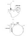
図1は、本発明による1実施例の頭部装着型ディスプレイ(画像表示装置)1を人の頭部Mに装着した様子を正面から見た模式図である。また、図2(a)は図1の場合の横顔を示した図、(b)は上から見た図である。この例は、小型のヘッドホン型の頭部支持部10を利用した例である。図1、図2において、顔の端部に位置する表示パネルを観察可能とするための導光路が内蔵された接眼窓保持部2が頭部支持部10から眼球E前面付近まで延びている。その接眼窓保持部2の先端部の接眼窓4を覗くことにより、表示された画像を確認することができる。このとき、外界景色の観察を妨げないよう、眼球正面範囲(図1参照)内に位置する部品は全て幅4mm以下となるように設定されている。 FIG. 1 is a schematic view of a head-mounted display (image display device) 1 according to an embodiment of the present invention mounted on a human head M as viewed from the front. 2A is a diagram showing a profile in the case of FIG. 1, and FIG. 2B is a diagram seen from above. In this example, a small headphone-type
ここで、眼球正面範囲内に位置する部品を全て幅4mm以下とする理由を説明する。人間の瞳孔径は明るさに応じて2〜8mmの間で変化する。眼球正面に配置された遮蔽物が瞳径よりも小さい場合には、遠方の景色は遮蔽物によって遮られることなく、観察可能である。ここで、眼球正面範囲内に位置する筐体部品である接眼窓保持部2を構成する部材を、平均的な瞳孔径サイズを基準として4mm以下というサイズにすることで、ほとんどの通常使用環境において、外界を遮蔽せずに観察することができるようになる。 Here, the reason why all the parts positioned within the frontal range of the eyeball are set to 4 mm or less in width will be described. The human pupil diameter varies between 2 and 8 mm depending on the brightness. When the shielding object arranged in front of the eyeball is smaller than the pupil diameter, the distant scenery can be observed without being obstructed by the shielding object. Here, in most normal use environments, the members constituting the eyepiece
なお、図1、図2の例において、棒状に伸びている頭部支持部10は後記する蛍光樹脂ロッドでできていてもよい。また、ヘッドホン型の頭部支持部10内には、補助照明光源や表示パネル駆動基板、各種制御基板、各種情報処理基板、メモリー、通信機能、スピーカー、操作インターフェース等が内蔵されていてもよい。 In the example of FIGS. 1 and 2, the
図3は、導光路が接眼窓保持部2に内蔵されていない構成例の正面から見た模式図である。頭部支持部10に保持され表示パネルが装着されている映像射出部11と、頭部支持部10に保持され接眼光学系5を保持するための接眼窓保持部2と、接眼窓保持部2に保持される接眼光学系5とからなり、表示パネルからの射出光は接眼窓保持部2の内側を通らずに、外側すなわち空中を通り、直接接眼光学系5に入射する。この場合の接眼窓保持部2も眼球正面範囲から見て、幅4mm以下、長さ10mm以上となるように設定されている。 FIG. 3 is a schematic view seen from the front of a configuration example in which the light guide path is not built in the eyepiece
この図3の場合は、図1〜図2の構成の効果に加えて、接眼窓保持部2を光路外に配置することにより、視野中心から遠ざけることができ、より自然に外界と電子画像の両方を観察することができる。 In the case of FIG. 3, in addition to the effects of the configuration of FIGS. 1 to 2, the eyepiece
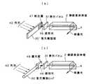
図4は、図1の構成における光学系部分の透視斜視図(a)と上側からみた図(b)である。接眼窓保持部2の入射端近傍に内蔵されて表示パネル3から射出された映像光は、接眼窓保持部2の内部を通り、反射部材6により方向を変え接眼窓4より眼球E方向に射出される。観察者はこの接眼窓4を覗くことで、表示パネル3に表示されている画像を観察することができる。接眼窓保持部2の左端は、実際は頭部支持部10へと繋がっており、頭部Mに保持される構造となっている。このとき、接眼窓保持部2の幅は観察者方向から見て4mm以下であり、接眼窓保持部2の長さは10mm以上である。この場合の反射部材6とは、光線を反射する部材なら何でもよく、例えばプリズム、ミラー等が利用できる。また、この場合の表示パネル3とは、小型の表示パネルなら何でもよく、例えば透過型又は反射型の液晶表示素子、自発光型の有機EL素子、無機EL等が利用できる。 4 is a perspective view (a) of the optical system portion in the configuration of FIG. 1 and a view (b) seen from above. The image light that is built in the vicinity of the entrance end of the eyepiece
図5に、本発明における頭部装着型画像表示装置の光学系の基本構成を示す。近点調節限界よりも近い位置に配置された表示パネル3を接眼レンズ5によりその映像光を眼球Eに投影することにより、観察者は表示パネル3の虚像である空中像3’を拡大観察することができる。このような構成により、小型な表示素子(表示パネル3)を用いても、大きな観察画角でその表示像を見ることが可能となる。 FIG. 5 shows the basic configuration of the optical system of the head-mounted image display apparatus according to the present invention. By projecting the image light onto the eyeball E by the
この場合の接眼レンズ5とは、正の屈折力を持った光学系であれば何でもよく、例えば、凸レンズ、凹面鏡、屈折率不均質レンズ等が利用できる。また、接眼レンズ5は正又は負の屈折力を持った光学素子を複数個組み合わせて正のレンズ群を形成したものを用いてもよい。 The
図6は、本発明の表示装置による外界の遮蔽の様子を模式図で説明するための図である。図6では、遮蔽物(ここでは、表示装置の筐体。図1〜図4の接眼窓保持部2が主として対応する。)が眼球E正面にあった場合でも、遮蔽物が瞳孔径よりも細い場合には、遠方の外界像は完全に遮蔽されることがない原理を示している。ここでは、遠方のある点からの光を入射光とすると、略平行な光として眼球Eに入射する。このとき、遮蔽物が瞳孔径よりも小さければ、平行光の一部は瞳孔を通り、網膜上の対応点に結像する。したがって、眼球正面に遮蔽物(表示装置の筐体)等があっても、瞳孔径よりも小さい太さのものであれば、外界の情報は失われることなく観察することが可能である(シースルーとなる)。 FIG. 6 is a diagram for explaining the state of shielding of the outside world by the display device of the present invention with a schematic diagram. In FIG. 6, even when the shielding object (here, the housing of the display device. The eyepiece
図6において、外界が明るくなり使用者の瞳孔が縮瞳した場合には、眼球正面方向の外界視野が絶たれ、外界視野が視認できなくなるという現象が起こる。そこで、ここでは、図7(a)のように、眼球正面(視軸)方向から遮蔽物(表示装置の筐体)をずらすことで、より外界像も自然に見ることができる。さらに、その際、表示装置による空中像(虚像)は、遮蔽物を瞳孔の端に配置しているにもかかわらず、眼球正面方向に見ることができ、完全なシースルー効果が得られる。すなわち、例えば図7(b)に光路図を示すように、外界を観察する使用者の眼球光軸(視軸)と本発明の表示装置の光軸とが互いに平行になるようにすることで、外界像に本発明の表示装置が映し出す像が重なり合って見えるようになる(シースルーとなる)。 In FIG. 6, when the outside world becomes bright and the pupil of the user contracts, a phenomenon occurs in which the outside field in the front direction of the eyeball is cut off and the outside field cannot be visually recognized. Therefore, here, as shown in FIG. 7A, the external image can be seen more naturally by shifting the shielding object (housing of the display device) from the front (view axis) direction of the eyeball. Further, at that time, an aerial image (virtual image) by the display device can be seen in the front direction of the eyeball even though the shielding object is arranged at the end of the pupil, and a complete see-through effect is obtained. That is, for example, as shown in the optical path diagram of FIG. 7B, the optical axis of the eyeball (visual axis) of the user observing the outside world and the optical axis of the display device of the present invention are parallel to each other. Then, the image projected by the display device of the present invention overlaps with the external image (becomes see-through).
以上のように、眼球Eの前方に位置する遮蔽物である接眼窓保持部2を10mm以上の長さにし、かつ、人間の平均的な瞳孔径4mmよりも細くすることで、図6に示すように、外界からの光束を完全に遮ることがなく、接眼窓保持部2の眼球Eと反対の向こうにある外界像があたかも接眼保持部2を透けて見え、視認できる。接眼窓保持部2の内部を外界光が通過することもないため、従来技術で問題となった不要反射も発生しない。すなわち、
『軽量かつ小型』
『ゴーストがない』
『大きな外界視野』
といった特徴を持つシーアラウンド効果を得ることができる。As described above, the ocular
"Lightweight and compact"
"No ghost"
"Big field of view"
A sea-around effect with the following characteristics can be obtained.
以下に、接眼窓保持部2に内蔵される光学系の構成例を示す。図8(a)は基本構成を示す図であり、表示パネル3からの光を導光する接眼窓保持部2と、それを眼球方向へ向きを変える反射部材6と、接眼レンズ5により構成されている。この構造により、大きさの嵩張る表示パネル3をなるべく眼球より遠避けることで、眼球正面範囲内に含まれる部位の幅を細くすることができる。 Below, the structural example of the optical system incorporated in the eyepiece window holding |
ただし、図8(a)の構造だと、表示パネル3のサイズが接眼窓保持部2を構成する部材の径で制限されてしまったり、接眼窓保持部2を長くすると、表示画面の画角を大きくとれないという問題がある。そこで、図8(b)に示すように、接眼窓保持部2を構成する部材をテーパー構造とすることで、眼球正面範囲に位置する部分はできるだけ細く、表示パネル3の部分を大きくとることによって、製造しやすい寸法の大きい表示パネル3を使用することができ、画角も大きくとることが可能である。 However, with the structure of FIG. 8A, if the size of the display panel 3 is limited by the diameter of the members constituting the eyepiece
図9(a)、(b)は、図8(a)と(b)の構造の画角の差を示す図である。図9(a)は、接眼窓保持部2が同一径による筐体21の構造となっており、図9(b)は、テーパー構造の筐体22で、接眼レンズ5側が細く、表示パネル3側が大きくなっている。図9の比較によると、例えば、筐体21、22の中央付近から接眼レンズ5にかけて眼球正面範囲に入っている条件で考えると、図9(a)、(b)どちらも眼球正面範囲内の筐体の径を4mm以下としたとき、図9(b)のテーパー構造の筐体22の方が、画角が大きくとれ、表示パネル3も大きくすることができる。ただし、図9中、光軸は符号21で、表示パネル3の端部からの光線を符号22で示してある。FIGS. 9A and 9B are views showing the difference in the angle of view between the structures of FIGS. 8A and 8B. 9 (a) is the
このように、眼球正面範囲にある筐体をできるだけ細くすることで、外界をより鮮明に観察することができる。また、表示パネル3を大きくできることで、画角を大きくすることができ、提示できる情報量が多くできると共に、表示パネル3の製造も容易となる。 In this way, the outside world can be observed more clearly by making the casing in the frontal range of the eyeball as thin as possible. Further, since the display panel 3 can be enlarged, the angle of view can be increased, the amount of information that can be presented can be increased, and the display panel 3 can be easily manufactured.
以上から明らかなように、接眼レンズ5の開口部分の大きさを小さくする程、本発明の表示装置は小型化が図れることとなり、より軽量で、装着者の目を覆わない構造が実現できる。眼球に対しての遮蔽となる表示装置の筐体が小さい程、より自然なシースルー効果が得られ、また、外観上の装着者の自然な表情が伝わりやすいといった効果が得られる。 As is clear from the above, as the size of the opening of the
反面、接眼レンズ5の開口から眼球に入射する光量が減り、表示画面の輝度が低下して見えたり、眼球と接眼レンズ5との位置調整が難しくなるという問題もある。 On the other hand, there is a problem that the amount of light incident on the eyeball from the opening of the
ところで、接眼レンズ5の開口サイズを小さくする上で、眼球正面に配置される筐体部品である接眼窓保持部2の長手方向、つまり、画面の横方向の開口サイズの縮小は小型化に余り寄与しない。 By the way, in order to reduce the opening size of the
そこで、図10(a)に図8の構成例における斜視図を、また、図10(b)にその構成例の観察時の接眼窓保持部2の先端部と眼球Eの位置関係を、また、図10(c)にそのときの接眼窓4と瞳孔径サイズの関係を示すように、眼球E正面に配置される筐体部品である接眼窓保持部2の長手方向と垂直な方向、つまり、この構成例における上下方向のみ接眼レンズ5の開口(接眼窓4)を縮小することで、小型化、シースルー効果向上等を図り、輝度低下等のデメリットを最小限に抑えることが可能である。 FIG. 10A shows a perspective view of the configuration example of FIG. 8, FIG. 10B shows a positional relationship between the distal end portion of the eyepiece
つまり、接眼レンズ5の接眼窓4を接眼窓保持部2の長手方向に長くなるような長方形形状とすることで、小型化、シースルー効果向上、輝度低下の軽減が可能であり、より使いやすい頭部装着型画像表示装置が実現できる。 That is, by making the
さらに、シースルー効果を得ながら、より見やすい接眼窓4の形状を考えると、上下方向は瞳孔径より小さく、左右方向は瞳孔径より大きくすることが望ましい。また、人間の平均的な瞳孔径4mmとして、上下方向は瞳孔径4mm以下で、左右方向は瞳孔径4mm以上であるような条件を満たす接眼窓4のサイズとすることで、より多くの観察状況で見やすい表示が可能となる。 Further, considering the shape of the
また、図11に接眼窓4の左右方向の長さに依存するアイポイントの左右の幅を示すが、図11(b)のように、接眼窓4を左右(接眼窓保持部2の長手方向)に長くすることでより、図11(a)の接眼窓4の左右のサイズが小さい場合に比べて、アイポイントが広くなり、接眼窓4に対して目のの位置が調整しやすくなり、また、接眼窓4から取り込む光量も増えるため、明るい画像を観察できる。 11 shows the left and right width of the eye point depending on the length of the
さて、図12は接眼窓保持部2内の光路中に2つの反射部材6、6’を用いて構成した例を示す図であり、2つの反射部材6、6’で光路を2回折り曲げることにより、バックライトの配置や、頭部支持部10との連結に有利な場合がある。すなわち、光路を2回折り曲げることで、レイアウト上の自由度が大きくなる。 Now, FIG. 12 is a view showing an example in which two reflecting
図13は、接眼窓保持部2に光学系を内蔵する場合に、その光学系として屈折率分布型レンズ23を利用した例を示す図であり、このような屈折率分布型レンズ23を用いることにより、通常の凸レンズで接眼光学系を構成するよりも、細い接眼窓保持部2の径で画角の大きな表示面が実現できる。すなわち、図13(b)に通常の接眼レンズ(凸レンズ)5で接眼光学系を構成した場合の画角を示し、図13(c)に屈折率分布レンズ23で構成した場合の画角を示しており、表示パネル3の端部から射出され、接眼窓中央を通る光線22に注目すると、両構成共導光路を伝わって接眼窓から射出されるが、図13(c)の屈折率分布レンズ23で構成された方を見ると、光線22が導光路中で次第に方向を変えるのに対し、通常の接眼レンズ5で構成された図13(b)の構成では、直線的に光線22が進むため、射出される時点での見込み角(画角)が異なり、図13(c)の屈折率分布レンズ23を利用した方が画角が大きくなっていることが分かる。 FIG. 13 is a diagram illustrating an example in which a refractive index distribution type lens 23 is used as an optical system in the case where an optical system is built in the
このように、接眼窓保持部2内に屈折率分布型レンズ23を接眼光学系に用いることにより、より細い径で大きな画角が実現可能である。 As described above, by using the gradient index lens 23 in the eyepiece
ここで、表示パネル3の有効径と接眼レンズ5の焦点距離との関係を検討する。図14に本発明の表示装置の光学系の諸パラメータの関係を示す。表示素子の有効表示面の対角寸法(有効径)をD、電子像視野の半画角をω/2、接眼光学系の焦点距離をfとするとき、近軸光学理論により、
ω/2=(D/2)/f ・・・(1)
の関係にある。Here, the relationship between the effective diameter of the display panel 3 and the focal length of the
ω / 2 = (D / 2) / f (1)
Are in a relationship.
主光線が使用者の瞳を通過できる主光線の最大傾斜角をξとし、使用者の瞳径をd、作動距離をWとすると、
ξ=(d/2)/W ・・・(2)
の関係にある。If the maximum tilt angle of the chief ray through which the chief ray can pass through the user's pupil is ξ, the pupil diameter of the user is d, and the working distance is W,
ξ = (d / 2) / W (2)
Are in a relationship.
周辺まで画像が明瞭に見えるための条件は、
ω/2<ξ ・・・(3)
であるので、
D/f<d/W ・・・(4)
となる。The conditions for the image to be clearly visible to the periphery are:
ω / 2 <ξ (3)
So
D / f <d / W (4)
It becomes.
ここで、室内における使用者の瞳の径dは、高々5mm程度なので、d=5mmを、また、瞬き時の睫毛の干渉等を考慮し、確保すべき作動距離Wは10mm程度なので、W=10mmをそれぞれ不等式(4)に代入すると、
D/f<0.5 ・・・(5)
となる。Here, the diameter d of the user's pupil in the room is at most about 5 mm, so d = 5 mm, and the working distance W to be secured is about 10 mm in consideration of interference of eyelashes at the time of blinking, so W = Substituting 10 mm into inequality (4),
D / f <0.5 (5)
It becomes.
表示装置の射出瞳位置を接眼窓近傍あるいは接眼窓と使用者の眼の瞳との間に設けることで、観察画像周縁の光束のケラレを小さくできるが、それでもD/fが不等式(5)の上限の0.5以上になると、ケラレが発生する。 By providing the exit pupil position of the display device in the vicinity of the eyepiece window or between the eyepiece window and the pupil of the user's eye, the vignetting of the light beam at the periphery of the observation image can be reduced, but the D / f is still in inequality (5). When the upper limit is 0.5 or more, vignetting occurs.
このように、本発明の表示装置の光学系にD/f<0.5という条件に設定することにより、小型な装置でありながら、観察時にケラレのない電子映像を観察することができるようになる。 As described above, by setting the optical system of the display device of the present invention to the condition of D / f <0.5, it is possible to observe an electronic image without vignetting at the time of observation even though the device is small. Become.
さて、本発明の表示装置の表示パネル3の照明用の光源であるが、外光を利用するようにすることが望ましい。その際、蛍光樹脂ロッドでその照明光源を構成することができる。以下に、その例を示す。 Now, although it is a light source for illumination of the display panel 3 of the display device of the present invention, it is desirable to use external light. In that case, the illumination light source can be comprised with the fluorescent resin rod. An example is shown below.
図15は、外光をバックライトに利用するための蛍光樹脂ロッドについての説明図である。蛍光樹脂ロッド30とは蛍光物質41が含まれた樹脂をロッド状に加工した部材である。この蛍光樹脂ロッド30は外光42が側面等から入射すると、蛍光物質41に一度吸収され、次にその蛍光物質41を光源として発光する。このときその部材がロッド形状であるとき、内部で発せられた光43は内部の側面で全反射を繰り返し、ロッド端面から射出される。つまり、ロッド内部で発光しロッド内部に閉じ込められた光がロッド端面から射出するため、ロッド端面は非常に明るく発光する。そのままでは、バックライトとして利用する側の端面と反対方向の端面からも発光してしまうが、利用しない端面をミラー44とすることで、反射された光が利用する側の端面からのみ射出されるようになるため、バックライトの光を有効利用することができる。なお、ミラー44とは、金属薄膜をロッド端面に蒸着してもよいし、コーナーキューブのような全反射を利用したプリズムでもよい。 FIG. 15 is an explanatory diagram of a fluorescent resin rod for using external light as a backlight. The
さらに、ロッド状に加工した部材の側面から入射した外光42も、蛍光物質41に吸収されなかったり、ロッドの全反射条件を満たさなかった光が側面から漏れ出すが、外光42が入射しない側あるいは取り付けたときに内側になる部分にミラー45を配置することで、利用されなかった光の一部を再利用することが可能である。 Further, the external light 42 incident from the side surface of the member processed into the rod shape is not absorbed by the fluorescent material 41 or light that does not satisfy the total reflection condition of the rod leaks from the side surface, but the external light 42 does not enter. By disposing the mirror 45 on the side or on the inner side when attached, it is possible to reuse part of the light that has not been used.
また、この構成を利用した照明を表示パネル3の照明光46として用いると、外界の明るさに応じて照明光46の明るさが変化する。この現象は、一般的にシースルー機能使用時には、外界が明るいときにより明るい照明が必要であり、外界が暗いときには、少ない照明でよいという利用シーンに一致する。 Moreover, when the illumination using this configuration is used as the
図16、図17は、このような蛍光樹脂ロッド30を利用した表示装置の構成例を示す図である。何れも、蛍光樹脂ロッド30端面から射出される照明光を表示パネル31又は36に入射させ、表示パネル31又は36による映像光が接眼窓保持部2内を導光し、接眼窓4から射出される。ここで、蛍光樹脂ロッド30は頭部支持部10へ接続されるか、又は、蛍光樹脂ロッド30自体が頭部支持部10となっていてもよい。 FIGS. 16 and 17 are diagrams illustrating a configuration example of a display device using such a
図16(a)、(b)、図17(a)は、透過型表示パネル31を利用した構成であり、図17(b)は、反射型表示パネル36を利用した構成である。図17(b)の場合は、反射型表示パネル36の前面から照明光46を入射させるために、反射型表示パネル36の表示側にハーフミラー等の光路分離光学素子49を配置する。 16A, 16B, and 17A are configurations using the
図18は、蛍光樹脂部材と導光板を組み合わせて表示パネルのバックライトとした構成例を示す図であり、図18(a)は、板状に構成した蛍光樹脂板30’の一部に射出溝47を設けることにより、その部分から光を射出させ、表示パネル31のバックライトとしている。図18(b)は、蛍光樹脂ロッド30の一端から出た光を蛍光樹脂ロッド30に接続された別部材の導光板48に入射させ、導光板48はその側面より表示パネル31方向へ導光された光を射出する機能により、表示パネル31を照明するものである。このように、蛍光樹脂部材と導光板を組み合わせることで、外光を表示パネル用照明として利用することができる。また、このような導光板を介することで、蛍光樹脂ロッド端面が表示パネルよりも小さいときでも、表示パネル全体をムラなく照明することができる。 FIG. 18 is a diagram showing a configuration example in which a fluorescent resin member and a light guide plate are combined to form a backlight of a display panel, and FIG. 18 (a) is injected into a part of a
このように、バックライトとして蛍光樹脂部材を利用することによって、表示パネルの照明に外光が利用できるため、低消費電力化でき、また、外界の明るさに応じて自然に照明光量が変化することから、特殊なセンサーを取り付けることなく利用する環境に応じて、適切な照明がなされる。また、外光を利用したバックライトを安価に構成することができる。 As described above, by using the fluorescent resin member as the backlight, since external light can be used for illumination of the display panel, power consumption can be reduced, and the amount of illumination light naturally changes according to the brightness of the outside world. Therefore, appropriate illumination is made according to the environment in which the sensor is used without attaching a special sensor. In addition, a backlight using external light can be configured at low cost.
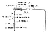
図19に蛍光樹脂ロッド30を用いた他の構成例を示す。図19おいて、表示素子として透過型液晶表示素子31を使用し、その表示素子31の照明に上記の蛍光樹脂ロッド30を用いており、蛍光樹脂ロッド30は外光に照らされて自家蛍光により発光し、その発光した光は蛍光樹脂ロッド30内部を全反射しながらその端面より射出し、反射プリズム33と照明用レンズ32を経てその自家蛍光による照明光で表示素子31が照明される。蛍光樹脂ロッド30の透過型液晶表示素子31側でない端面は、全反射プリズム(コーナーキューブ)34の形状とされており、表示素子31と反対に進行する蛍光光を折り返して再利用している。そして、この例では、表示素子31と接眼窓4の間に一端が90°全反射型の透明ロッド9が配置され、透明ロッド9の光路が90°曲がった射出端の接眼窓4位置に接眼レンズを構成する凸レンズ15が貼り付けられており、その全体が接眼窓保持部2で覆われて構成されている。したがって、接眼レンズの凸レンズ15と接眼窓4が一体化されている。この例では、蛍光樹脂ロッド30を表示素子31を照らす照明光源として利用することで、頭部装着型画像表示装置の消費電力を小さくでき、さらに、外界が明るい場合は、光源輝度も上がるので、電子映像が外界の明るさに負けて視認視認し難くなるという不具合が回避できる。なお、図19の例では、蛍光樹脂ロッド30は未使用時に、図20に示すように、ヒンジ回転軸35を中心に矢印方向へ畳んで収納できるようになっている。このように構成することにより、眼鏡に搭載したままの状態でも、眼鏡と一緒に折り畳み収納することができる。 FIG. 19 shows another configuration example using the
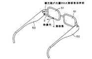
図21は、通常用いる眼鏡に本発明による頭部装着型画像表示装置を取り付けた例を示す図である。眼鏡フレーム50に沿って蛍光樹脂ロッド30が配置され、その端面からの光を一度反射部材にて90°折り曲げ、表示パネル31に入射させ、表示パネル31からの映像光を接眼窓保持部2内を導光して、接眼窓4より射出させる。このとき、蛍光樹脂ロッド30の他の端面は光の利用効率を高めるためミラー44が設けられていてもよく、また、外光42が当たらない眼鏡フレーム50と蛍光樹脂ロッド30との境界はミラー45が設けられていてもよい。さらに、補助光源37を利用することで、全くの暗闇でも利用することが可能となる。ここでは、蛍光樹脂ロッド30の他端に補助光源37を配置してあり、ミラー44と補助光源37を切り換えて使用することができる。 FIG. 21 is a diagram showing an example in which the head-mounted image display device according to the present invention is attached to normally used glasses. A
補助光源37が発する光の波長は、蛍光樹脂ロッド30の蛍光物質を効率的に励起できる波長帯に一致しているのがよい。これにより、蛍光樹脂ロッド30は補助光源37からの補助光により効率的に励起され、この蛍光により表示パネル31が照明されるので、補助光源37は少ない消費電力で明るい照明が可能となる。 The wavelength of the light emitted from the auxiliary light source 37 should match the wavelength band in which the fluorescent material of the
あるいは、補助光源37が発する光の波長は、蛍光樹脂ロッド30の吸収度が大きな波長帯を避けるとよく、これにより補助光源37が発した光が蛍光樹脂ロッド30で吸収されることなく表示パネル31を照明できるので、補助光源37は少ない消費電力で明るい照明ができる。 Alternatively, the wavelength of the light emitted from the auxiliary light source 37 should avoid a wavelength band where the absorbance of the
さらに、補助光源37が発する光の色を、蛍光樹脂ロッド30の発する蛍光色と異なる色とし、使用者に注意を促したいときにこの補助光源37を点滅させるようにしてもよい。この点滅により、使用者が観察する画像は、その明るさだけでなく、色が変化し、注意されていることに気がつきやすくなる。 Furthermore, the color of the light emitted from the auxiliary light source 37 may be different from the fluorescent color emitted from the
また、蛍光樹脂ロッド30を頭部側面に配置した場合に外光が当たらない部分、頭部と蛍光樹脂ロッド30の間に電気基板や配線等を配置しても、外光の入射の妨げになることはない。 Further, when the
このように、通常の眼鏡に本発明の頭部装着型画像表示装置を取り付けることにより、普段眼鏡を利用する人にも本発明の頭部装着型画像表示装置が使用可能となる。また、その際に、補助光源を設けることにより、暗い環境にも対応可能である。さらに、外光を利用した照明光源として蛍光樹脂ロッドを用い、その蛍光樹脂の吸収波長を考慮して補助光源を選定することにより、低消費電力化が図れる。その蛍光樹脂の蛍光色と異なる波長の補助光源に使用することにより、注意喚起の信号として利用できる。さらには、蛍光樹脂ロッドの外光入射部の反対側に配線、基板類を配置することで、外光入射の妨げにならない。 As described above, by attaching the head-mounted image display device of the present invention to normal glasses, the head-mounted image display device of the present invention can be used even by a person who normally uses glasses. At that time, by providing an auxiliary light source, it is possible to cope with a dark environment. Furthermore, by using a fluorescent resin rod as an illumination light source using external light and selecting an auxiliary light source in consideration of the absorption wavelength of the fluorescent resin, power consumption can be reduced. By using it as an auxiliary light source having a wavelength different from that of the fluorescent color of the fluorescent resin, it can be used as a warning signal. Furthermore, by arranging wirings and substrates on the opposite side of the fluorescent resin rod to the external light incident portion, it does not interfere with the external light incidence.
図22は、本発明の頭部装着型画像表示装置を眼鏡フレームに組み込んだ例を示す図である。接眼窓保持部2が眼鏡フレーム50内部に組み込まれ、図では眼鏡レンズ51の中央の下部に接眼窓4があり、映像光が射出される。このように、本発明の頭部装着型画像表示装置を眼鏡フレームに当初から組み込むことで、煩雑な取り付け作業が必要なく、取り付け機構等も不要であるため、より自然なデザインが可能となる。 FIG. 22 is a diagram showing an example in which the head-mounted image display device of the present invention is incorporated in a spectacle frame. The eyepiece
図23は光ファイバーイメージガイドを利用した構成例を示す図である。頭部装着型画像表示装置において、装着時の煩わしさを取り除くことが重要であり、それには、目元付近に配置する部品をできるだけ小さくすることで効果が期待できる。通常、目元付近に表示パネルが配置されるため、目元付近の装置が大型化してしまっていた。そこで、表示パネル3を目元から離し、表示パネル3の映像を光ファイバーイメージガイド55で目元付近まで伝送し、伝送された映像を2次映像として、その2次映像を光学系で拡大観察するようにすることで、目元付近に配置する装置を極力小さくすることができる。また、光ファイバーイメージガイド55はある程度柔軟性があるため、折り曲げて使用することもでき、色々なデザインや調整機構に対応しやすい構成となる。 FIG. 23 is a diagram showing a configuration example using an optical fiber image guide. In the head-mounted image display device, it is important to remove the troublesomeness at the time of wearing, and the effect can be expected by minimizing the parts arranged near the eyes. Usually, since the display panel is arranged near the eyes, the device near the eyes has been enlarged. Therefore, the display panel 3 is moved away from the eyes, the image on the display panel 3 is transmitted to the vicinity of the eyes by the optical
また、図23では、無線で接続されたコントローラー56から映像や情報を受け取り、表示パネル3に表示している様子が図示されている。ここで言うコントローラー56とは、専用のコントローラーや携帯電話、携帯型情報機器(PDA)等何でもよい。 Further, FIG. 23 illustrates a state in which video and information are received from the controller 56 connected wirelessly and displayed on the display panel 3. The controller 56 mentioned here may be anything such as a dedicated controller, a mobile phone, or a portable information device (PDA).
以上のように、光ファイバーイメージガイドを用いて表示パネルの映像を2次映像として伝送するようにすることにより、表示パネルや配線、電気基板類を目元付近に配置する必要がなくなり、装着感やデザインに悪影響を与える目元付近の装置の大型化を防ぐことができる。また、光ファイバーイメージガイドはある程度柔軟性があるため、折り曲げても使用することもでき、色々なデザインや調整機構に対応しやすい。 As described above, by transmitting the image of the display panel as a secondary image using the optical fiber image guide, it is not necessary to arrange the display panel, wiring, and electric boards near the eyes, and the feeling of wearing and design It is possible to prevent an increase in the size of the device in the vicinity of the eyes that adversely affects the eyes. In addition, since the optical fiber image guide is flexible to some extent, it can be used even when it is bent, and it is easy to cope with various designs and adjustment mechanisms.
図23のような構成において、無線での映像や情報のやり取りが一般化すると、情報漏洩の問題が生じてくる。電気的又はソフトウェア的に対策するだけでは不安が残る場合も生じてくる。その場合に有効なのが、暗号化光ファイバーイメージガイドを組み込んだ頭部装着型画像表示装置である。図24は、暗号化光ファイバーイメージガイド57の構成と作用を説明する図であり、通常の光ファイバーイメージガイドでは、表示パネル3上に表示された映像をそのままのパターンで伝送する。例えば、表示パネル3上の画素1個に対して光ファイバー1本を配置して、画素の相対配置を維持したまま映像を伝送する。ここで言う暗号化光ファイバーイメージガイドとは、表示パネル3上の画素1個に対して光ファイバー58を1本を割り当て、伝送の途中で光ファイバー58の相対配置をランダムに入れ替えることによって、表示パネル3上の映像とは全く異なるパターンの映像を表示するものである。図中では、表示パネル3上に全く意味をなさない画像が表示されているが、それを伝送する光ファイバー58の配置が途中で相互に入れ替わっており、伝送後の2次映像上では“F”という文字が表示されている。 In the configuration shown in FIG. 23, when wireless video and information exchange is generalized, an information leakage problem occurs. There may be cases where anxiety remains only by taking electrical or software measures. In this case, a head-mounted image display device incorporating an encrypted optical fiber image guide is effective. FIG. 24 is a diagram for explaining the configuration and operation of the encrypted optical fiber image guide 57. In a normal optical fiber image guide, the image displayed on the display panel 3 is transmitted in the same pattern. For example, one optical fiber is arranged for one pixel on the display panel 3, and an image is transmitted while maintaining the relative arrangement of the pixels. The encrypted optical fiber image guide here refers to the display panel 3 by assigning one
予め表示パネル3上の画素と伝送された2次映像上の画素の対応関係を調べることにより、2次映像として整った映像として見えるように、表示パネル3上に実際に表示する映像を画素単位で入れ替える。コントローラー56側からはこの入れ替えられた映像として全く意味をなさない画像情報が無線信号にて送信されるため、もし他人が傍受したとしても、その人には全く意味のない映像としか見えないため、セキュリティーは保たれることとなる。また、この暗号化光ファイバーイメージガイド57は製品毎に異なった固有の配置となっており、同じ製品を用いても、他人が傍受することはできない(図26)。 By examining the correspondence between the pixels on the display panel 3 and the pixels on the transmitted secondary video in advance, the video actually displayed on the display panel 3 is displayed on a pixel-by-pixel basis so that it can be seen as a secondary video. Replace with. Since the image information that does not make any sense as the replaced video is transmitted by radio signal from the controller 56 side, even if another person intercepts it, the person can only see the video that has no meaning at all. Security is maintained. Further, the encrypted optical fiber image guide 57 has a unique arrangement different for each product, and even if the same product is used, others cannot intercept it (FIG. 26).
このように、表示部と別体で構成されるコントローラー(画像データ送信部)から映像や情報を無線で送信する際に、ソフトウェア的、電気的なセキュリティー対策に加えて、物理(光学)構造的にも安全性が高められる。 In this way, when video and information are transmitted wirelessly from a controller (image data transmission unit) that is configured separately from the display unit, in addition to software and electrical security measures, physical (optical) structural Safety is also improved.
図25は画像縮小光ファイバーイメージガイド55’の説明図である。現在の技術において、非常に小さい表示パネルを製造することは難しく、コストが高くなってしまう。そこで、製造が容易なサイズの表示パネルを用いて、なるべく邪魔にならない部分に装着し、画像縮小光ファイバーイメージガイド55’にて表示パネル3よりも小さい2次映像を形成させ、これを光学系にて観察することにより、大きい表示パネルを使用しながら、目元付近はコンパクトな装着感のより頭部装着型画像表示装置が実現することが可能である。 FIG. 25 is an explanatory diagram of an image reducing optical fiber image guide 55 '. In the current technology, it is difficult to manufacture a very small display panel, which increases the cost. Therefore, a display panel with a size that is easy to manufacture is used, and is attached to a part that is not obstructive as much as possible, and a secondary image smaller than the display panel 3 is formed by the image reduction optical fiber image guide 55 ′, and this is used as an optical system. By observing the head, it is possible to realize a head-mounted image display device with a feeling of compact wearing near the eyes while using a large display panel.
このように、画像縮小光ファイバーイメージガイドを利用することにより、実際の表示パネルよりも小さい映像を2次映像として目元付近に表示可能となる。本発明の頭部装着型画像表示装置は、表示パネルとして極端に小さい部類の表示パネルを使用するが、これにより製造が容易で低コストで入手可能なやや大きめの表示パネルが使用可能となる。 As described above, by using the image reducing optical fiber image guide, an image smaller than the actual display panel can be displayed as a secondary image in the vicinity of the eyes. The head-mounted image display device of the present invention uses an extremely small type of display panel as a display panel. This makes it possible to use a slightly larger display panel that is easy to manufacture and can be obtained at low cost.
図26は、図24のような暗号化光ファイバーイメージガイドが用いられた機器におけるコンテンツ配信の模式図を示している。製品No.1〜3までの製品があり、それぞれにおいて暗号化光ファイバーイメージガイドの配置が異なっており、それらを解析してコード化したものが暗号キーとなっている。コンテンツ配信センターはそれぞれの製品No.に対応した暗号キーの情報を持っており、それを基に映像信号を画像処理する。そして、画像処理済のコンテンツデータを対応する製品No.を持つ人に配信する。これらの処理により、そのコンテンツデータはある特定のNo.を持つ製品でしか再生して見ることができず、他の製品へコピー又は不正にコンテンツのみを入手した場合においても、他の製品で再生した場合には、全く意味をなさない画像となってしまう。したがって、デジタルコンテンツを配信する際に問題となっている不正コピーや不正使用の問題が解決できる。 FIG. 26 shows a schematic diagram of content distribution in a device using the encrypted optical fiber image guide as shown in FIG. Product No. There are products from 1 to 3, and the arrangement of encrypted optical fiber image guides is different in each, and an encryption key is obtained by analyzing and encoding them. Each content distribution center has a product no. The video signal is image-processed based on the encryption key information corresponding to. Then, the image data processed content data corresponds to the corresponding product No. Deliver to people with. Through these processes, the content data is stored in a specific number. Can only be played back and viewed with a product that has a copy of it, or even if the content is copied or illegally obtained only when it is played back with another product, the image is completely meaningless. End up. Therefore, it is possible to solve the problem of unauthorized copying and unauthorized use that are problematic when distributing digital contents.
以上の、本発明の頭部装着型画像表示装置は、例えば次のように構成することができる。 The above-described head-mounted image display apparatus of the present invention can be configured as follows, for example.
〔1〕 少なくとも、表示素子と、接眼光学系と、接眼窓と、接眼窓保持部と、筐体と、これら全体を使用者の頭部に固定するための支持部とからなる頭部装着型画像表示装置であって、筐体は表示素子を覆い、接眼窓保持部は接眼窓を使用者の視界内に保持し、接眼光学系は表示素子が表示する表示画像の虚像を作り、接眼窓はその虚像を形成する光束が使用者の眼に向かい射出する窓であり、接眼窓保持部を構成する部材は、前記接眼窓から根元に向かって10mm以上の範囲にて、一部の突起を除き、使用者の視軸方向への投影断面の幅が4mm以下であり、シーアラウンド機能を有することを特徴とする頭部装着型画像表示装置。 [1] Head-mounted type including at least a display element, an eyepiece optical system, an eyepiece window, an eyepiece window holding unit, a housing, and a support unit for fixing the whole to the user's head. An image display device, wherein the casing covers the display element, the eyepiece window holding unit holds the eyepiece window in the user's field of view, and the eyepiece optical system creates a virtual image of the display image displayed by the display element, Is a window through which the luminous flux forming the virtual image emerges toward the user's eye, and the member constituting the eyepiece window holding part has a part of protrusions in the range of 10 mm or more from the eyepiece window toward the root. A head-mounted image display device having a see-around function, except that the width of the projected cross section in the visual axis direction of the user is 4 mm or less.
〔2〕 接眼窓を構成する部材は、その使用者の視軸方向への投影断面の幅が4mm以下であり、シースルー機能を有することを特徴とする上記1記載の頭部装着型画像表示装置。 [2] The head-mounted image display device according to 1 above, wherein the member constituting the eyepiece window has a see-through function in which a width of a projected section in the visual axis direction of the user is 4 mm or less. .
〔3〕 接眼窓保持部と接眼窓との間には、光軸を使用者の眼の方向に屈曲する全反射のミラー又はプリズムが配置されていることを特徴とする上記1又は2記載の頭部装着型画像表示装置。 [3] The total reflection mirror or prism that bends the optical axis in the direction of the user's eye is disposed between the eyepiece window holding unit and the eyepiece window. Head-mounted image display device.
〔4〕 接眼窓保持部は、頭部装着時に略水平に配置されるよう保持されることを特徴とする上記1から3の何れか1項記載の頭部装着型画像表示装置。 [4] The head-mounted image display device according to any one of the above items 1 to 3, wherein the eyepiece window holding unit is held so as to be arranged substantially horizontally when the head is mounted.
〔5〕 接眼窓と全反射のミラー又は接眼窓と全反射のプリズム全体が、接眼窓保持部の長手方向を回転軸にして回転調整できる回転機構を有することを特徴とする上記3記載の頭部装着型画像表示装置。 [5] The head according to the above item 3, wherein the eyepiece window and the total reflection mirror or the whole eyepiece window and the total reflection prism have a rotation mechanism capable of rotating and adjusting the longitudinal direction of the eyepiece window holding portion as a rotation axis. Part-mounted image display device.
〔6〕 表示素子の表示面に垂直な方向を回転軸として表示素子を使用者が回転調整できる回転機構を有することを特徴とする上記3記載の頭部装着型画像表示装置。 [6] The head-mounted image display device as described in 3 above, wherein the head-mounted image display device has a rotation mechanism that allows a user to adjust the rotation of the display element about a direction perpendicular to the display surface of the display element.
〔7〕 接眼光学系の一部又は全部が接眼窓と一体化していることを特徴とする上記1から6の何れか1項記載の頭部装着型画像表示装置。 [7] The head-mounted image display device according to any one of 1 to 6, wherein a part or all of the eyepiece optical system is integrated with an eyepiece window.
〔8〕 接眼光学系の一部又は全部が接眼窓保持部に内蔵されていることを特徴とする上記1から7の何れか1項記載の頭部装着型画像表示装置。 [8] The head-mounted image display device as described in any one of 1 to 7 above, wherein part or all of the eyepiece optical system is built in the eyepiece window holder.
〔9〕 接眼窓支持部に内蔵される接眼光学系は、平行光束を収斂させる作用を有する光学系であることを特徴とする上記8記載の頭部装着型画像表示装置。 [9] The head-mounted image display device as described in 8 above, wherein the eyepiece optical system incorporated in the eyepiece window support section is an optical system having an action of converging parallel light beams.
〔10〕 接眼窓は長方形形状であり、その長辺が接眼窓保持部の長手方向と同一方向であることを特徴とする上記1から9の何れか1項記載の頭部装着型画像表示装置。 [10] The head-mounted image display device according to any one of 1 to 9, wherein the eyepiece window has a rectangular shape, and a long side thereof is in the same direction as a longitudinal direction of the eyepiece window holding portion. .
〔11〕 接眼窓の開口サイズは、上下方向は瞳孔径よりも小さく、左右方向は瞳孔径よりも大きいことを特徴とする上記1から9の何れか1項記載の頭部装着型画像表示装置。 [11] The head-mounted image display device according to any one of 1 to 9, wherein an opening size of the eyepiece window is smaller than the pupil diameter in the vertical direction and larger than the pupil diameter in the left-right direction. .
〔12〕 接眼窓の開口サイズは、上下方向は4mm以下であり、左右方向は4mm以上であることを特徴とする上記1から9の何れか1項記載の頭部装着型画像表示装置。 [12] The head-mounted image display device as described in any one of 1 to 9 above, wherein the opening size of the eyepiece window is 4 mm or less in the vertical direction and 4 mm or more in the horizontal direction.
〔13〕 筐体と接眼窓保持部は、全反射のミラー又はプリズムあるいは光ファイバーイメージガイドを介して連結されていることを特徴とする上記1から12の何れか1項記載の頭部装着型画像表示装置。 [13] The head-mounted image as described in any one of [1] to [12], wherein the housing and the eyepiece window holding unit are connected via a total reflection mirror or prism or an optical fiber image guide. Display device.
〔14〕 照明部があり、照明部と筐体とは全反射のミラー又はプリズム、導光板、あるいは、ライトガイドを介して連結されていることを特徴とする上記1から13の何れか1項記載の頭部装着型画像表示装置。 [14] There is an illuminating unit, and the illuminating unit and the casing are connected to each other via a total reflection mirror or prism, a light guide plate, or a light guide. The head-mounted image display device described.
〔15〕 接眼光学系は凸レンズからなることを特徴とする上記9記載の頭部装着型画像表示装置。 [15] The head mounted image display device as described in 9 above, wherein the eyepiece optical system comprises a convex lens.
〔16〕 接眼光学系はラジアル方向に屈折率が徐々に高くなる光学媒質からなることを特徴とする上記8又は9記載の頭部装着型画像表示装置。 [16] The head-mounted image display device as described in 8 or 9 above, wherein the eyepiece optical system comprises an optical medium whose refractive index gradually increases in the radial direction.
〔17〕 表示素子の有効表示面の対角寸法をD、接眼光学系の焦点距離をfとするとき、D/f<0.5を満たすことを特徴とする上記1から16の何れか1項記載の頭部装着型画像表示装置。 [17] Any one of 1 to 16 above, wherein D / f <0.5 is satisfied, where D is the diagonal dimension of the effective display surface of the display element and f is the focal length of the eyepiece optical system. The head-mounted image display device according to the item.
〔18〕 射出瞳位置は接眼窓近傍あるいは接眼窓と使用者の眼の瞳との間にあることを特徴とする上記17記載の頭部装着型画像表示装置。 [18] The head mounted image display device as described in 17 above, wherein the exit pupil position is in the vicinity of the eyepiece window or between the eyepiece window and the pupil of the user's eye.
〔19〕 表示素子を射出する電子映像形成光束が、接眼窓保持部の外側を通過することを特徴とする上記1記載の頭部装着型表示装置。 [19] The head-mounted display device as described in 1 above, wherein the electronic image forming light beam emitted from the display element passes outside the eyepiece window holder.
〔20〕 表示素子を照明する照明用の光源を有し、その光源を蛍光樹脂ロッドで構成したことを特徴とする上記1記載の頭部装着型表示装置。 [20] The head-mounted display device as described in [1], wherein the head-mounted display device has a light source for illumination that illuminates the display element, and the light source is formed of a fluorescent resin rod.
〔21〕 蛍光樹脂ロッドの表示パネルと反対側に向いた端面はミラーコート処理又はコーナーキューブ形状をしていることを特徴とする上記20記載の頭部装着型表示装置。 [21] The head-mounted display device as described in 20 above, wherein the end surface of the fluorescent resin rod facing away from the display panel has a mirror coat process or a corner cube shape.
〔22〕 蛍光樹脂ロッドの側面で外光が入射しない側の側面にミラーを配置したことを特徴とする上記20記載の頭部装着型表示装置。 [22] The head-mounted display device as described in 20 above, wherein a mirror is disposed on the side surface of the fluorescent resin rod on the side where no external light is incident.
〔23〕 使用者の眼と接眼窓の位置関係で、眼の視軸は接眼窓に重ならず、接眼窓の主光線は瞳孔径内に入射することを特徴とする上記1から22の何れか1項記載の頭部装着型画像表示装置。 [23] Any one of 1 to 22 above, wherein the visual axis of the eye does not overlap the eyepiece window due to the positional relationship between the user's eye and the eyepiece window, and the chief ray of the eyepiece window enters the pupil diameter. A head-mounted image display device according to claim 1.
〔24〕 接眼窓保持部を構成する部材は、接眼窓側は細く、表示素子側は太くなるようなテーパー構造のものであること特徴とする上記1記載の頭部装着型表示装置。 [24] The head-mounted display device as described in [1] above, wherein the member constituting the eyepiece window holding portion has a tapered structure in which the eyepiece window side is thin and the display element side is thick.
〔25〕 表示素子の映像を光ファイバーイメージガイドにより伝送して形成された2次映像を接眼窓保持部及び接眼窓を通して観察するようにしたこと特徴とする上記1記載の頭部装着型表示装置。 [25] The head-mounted display device as described in [1] above, wherein a secondary image formed by transmitting an image of the display element through an optical fiber image guide is observed through the eyepiece window holder and the eyepiece window.
〔26〕 光ファイバーイメージガイドとして不規則に配列された暗号化光ファイバーイメージガイドが用いられ、その暗号化光ファイバーイメージガイドに対応して、2次映像が映像として観察可能なように、表示素子上に映像を表示させることを特徴とする上記25記載の頭部装着型表示装置。 [26] Randomly arranged encrypted optical fiber image guides are used as optical fiber image guides, and images are displayed on the display elements so that secondary images can be observed as images corresponding to the encrypted optical fiber image guides. 26. The head-mounted display device as described in 25 above, wherein:
〔27〕 表示素子上の映像サイズよりも光ファイバーイメージガイドにより伝送された2次映像サイズが小さくなるように、光ファイバーイメージガイドの各画素のピッチを入射側と射出側で異ならせたことを特徴とする上記25記載の頭部装着型表示装置。 [27] The pitch of each pixel of the optical fiber image guide is made different between the incident side and the exit side so that the secondary image size transmitted by the optical fiber image guide is smaller than the image size on the display element. 26. The head-mounted display device according to 25 above.
〔28〕 表示素子を含む表示部と接眼窓保持部と接眼光学系と接眼窓とが眼鏡フレームに内蔵されていることを特徴とする上記1から27の何れか1項記載の頭部装着型画像表示装置。 [28] The head-mounted type according to any one of 1 to 27 above, wherein a display unit including a display element, an eyepiece window holding unit, an eyepiece optical system, and an eyepiece window are built in the spectacle frame. Image display device.
M…人の頭部
E…眼球
1…頭部装着型ディスプレイ(画像表示装置)
2…接眼窓保持部
21…同一径による筐体(接眼窓保持部)
22…テーパー構造の筐体(接眼窓保持部)
3…表示パネル
3’…空中像
4…接眼窓
5…接眼光学系(接眼レンズ)
6、6’…反射部材
9…透明ロッド
10…頭部支持部
11…映像射出部
15…凸レンズ
21…光軸
22…表示パネルの端部からの光線
23…屈折率分布型レンズ
30…蛍光樹脂ロッド
30’…蛍光樹脂板
31…透過型表示パネル(透過型液晶表示素子)
32…照明用レンズ
33…反射プリズム
34…全反射プリズム(コーナーキューブ)
35…ヒンジ回転軸
36…反射型表示パネル
37…補助光源
41…蛍光物質
42…外光
43…内部で発せられた光
44、45…ミラー
46…照明光
49…光路分離光学素子
47…射出溝
48…導光板
50…眼鏡フレーム
51…眼鏡レンズ
55…光ファイバーイメージガイド
55’…画像縮小光ファイバーイメージガイド
56…コントローラー
57…暗号化光ファイバーイメージガイド
58…光ファイバー
100…柱状透明支持部材
101…不要光M ... human head E ... eyeball 1 ... head-mounted display (image display device)
2 ...
22 ... Tapered housing (eyepiece window holder)
3 ... Display panel 3 '...
6, 6 '... Reflective member 9 ...
32 ...
35 ... Hinge rotating shaft 36 ... Reflective display panel 37 ... Auxiliary light source 41 ... Fluorescent material 42 ... Outside light 43 ... Light 44, 45 ...
Claims (28)
Translated fromJapanesePriority Applications (1)
| Application Number | Priority Date | Filing Date | Title |
|---|---|---|---|
| JP2005137275AJP4766913B2 (en) | 2004-05-17 | 2005-05-10 | Head-mounted image display device |
Applications Claiming Priority (3)
| Application Number | Priority Date | Filing Date | Title |
|---|---|---|---|
| JP2004145838 | 2004-05-17 | ||
| JP2004145838 | 2004-05-17 | ||
| JP2005137275AJP4766913B2 (en) | 2004-05-17 | 2005-05-10 | Head-mounted image display device |
Publications (2)
| Publication Number | Publication Date |
|---|---|
| JP2006003879A JP2006003879A (en) | 2006-01-05 |
| JP4766913B2true JP4766913B2 (en) | 2011-09-07 |
Family
ID=35772283
Family Applications (1)
| Application Number | Title | Priority Date | Filing Date |
|---|---|---|---|
| JP2005137275AExpired - Fee RelatedJP4766913B2 (en) | 2004-05-17 | 2005-05-10 | Head-mounted image display device |
Country Status (1)
| Country | Link |
|---|---|
| JP (1) | JP4766913B2 (en) |
Cited By (2)
| Publication number | Priority date | Publication date | Assignee | Title |
|---|---|---|---|---|
| US9804390B2 (en) | 2014-03-11 | 2017-10-31 | Olympus Corporation | Virtual image observation optical system and light guide prism |
| US10168454B2 (en) | 2014-03-10 | 2019-01-01 | Olympus Corporation | Head-mounted display device |
Families Citing this family (55)
| Publication number | Priority date | Publication date | Assignee | Title |
|---|---|---|---|---|
| JP4893372B2 (en)* | 2007-03-02 | 2012-03-07 | ブラザー工業株式会社 | Image display device |
| JP2009075195A (en)* | 2007-09-19 | 2009-04-09 | Olympus Corp | Eyeglass type image display device and eyeglasses with image display device |
| JP5137644B2 (en)* | 2008-03-21 | 2013-02-06 | オリンパス株式会社 | Eyeglass-type image display device |
| JP5147623B2 (en)* | 2008-09-29 | 2013-02-20 | オリンパス株式会社 | Head-mounted image display device |
| JP2010145718A (en)* | 2008-12-18 | 2010-07-01 | Olympus Corp | Head mount image display |
| JP5173869B2 (en)* | 2009-01-28 | 2013-04-03 | オリンパス株式会社 | Head-mounted image display device |
| JP2010230716A (en)* | 2009-03-25 | 2010-10-14 | Olympus Corp | Head-mounted image display device |
| JP5389492B2 (en) | 2009-03-25 | 2014-01-15 | オリンパス株式会社 | Head-mounted image display device |
| JP2010232718A (en)* | 2009-03-25 | 2010-10-14 | Olympus Corp | Head-mounted image display apparatus |
| JP5242477B2 (en)* | 2009-03-25 | 2013-07-24 | オリンパス株式会社 | Glasses-mounted image display device |
| JP5185865B2 (en)* | 2009-03-25 | 2013-04-17 | オリンパス株式会社 | Spectacle-type image display device and spectacle frame used therefor |
| JP2011059444A (en)* | 2009-09-10 | 2011-03-24 | Olympus Corp | Spectacles-type image display device |
| JP5372820B2 (en)* | 2010-03-24 | 2013-12-18 | オリンパス株式会社 | Head-mounted display device |
| JP5363389B2 (en)* | 2010-03-24 | 2013-12-11 | オリンパス株式会社 | Head-mounted image display device |
| JP5363390B2 (en)* | 2010-03-24 | 2013-12-11 | オリンパス株式会社 | Head-mounted image display device |
| EP2372431A3 (en) | 2010-03-24 | 2011-12-28 | Olympus Corporation | Head-mounted type display device |
| JP5567924B2 (en) | 2010-07-27 | 2014-08-06 | オリンパス株式会社 | Prism optical system, image display device using prism optical system, and imaging device using prism optical system |
| JP5646238B2 (en) | 2010-07-27 | 2014-12-24 | オリンパス株式会社 | Image display device |
| JP5603716B2 (en) | 2010-09-06 | 2014-10-08 | オリンパス株式会社 | PRISM OPTICAL SYSTEM, IMAGE DISPLAY DEVICE AND IMAGING DEVICE USING PRISM OPTICAL SYSTEM |
| JP5576746B2 (en) | 2010-09-06 | 2014-08-20 | オリンパス株式会社 | Decentered optical system, and image display device and imaging device using decentered optical system |
| JP5496030B2 (en)* | 2010-09-16 | 2014-05-21 | オリンパス株式会社 | Head-mounted image display device |
| JP5485093B2 (en) | 2010-09-16 | 2014-05-07 | オリンパス株式会社 | Head-mounted image display device |
| US8837880B2 (en) | 2010-10-08 | 2014-09-16 | Seiko Epson Corporation | Virtual image display device |
| JP5633406B2 (en) | 2011-02-04 | 2014-12-03 | セイコーエプソン株式会社 | Virtual image display device |
| JP2012163656A (en) | 2011-02-04 | 2012-08-30 | Seiko Epson Corp | Virtual image display device |
| JP5760465B2 (en) | 2011-02-04 | 2015-08-12 | セイコーエプソン株式会社 | Virtual image display device |
| JP5742263B2 (en) | 2011-02-04 | 2015-07-01 | セイコーエプソン株式会社 | Virtual image display device |
| JP5720290B2 (en) | 2011-02-16 | 2015-05-20 | セイコーエプソン株式会社 | Virtual image display device |
| JP5698578B2 (en)* | 2011-03-24 | 2015-04-08 | オリンパス株式会社 | Head-mounted display device |
| JP2013044896A (en)* | 2011-08-23 | 2013-03-04 | Brother Ind Ltd | Head-mounted display |
| JP6008086B2 (en) | 2012-03-26 | 2016-10-19 | セイコーエプソン株式会社 | Head-mounted display device |
| JP6060512B2 (en) | 2012-04-02 | 2017-01-18 | セイコーエプソン株式会社 | Head-mounted display device |
| EP2932330A1 (en)* | 2012-12-13 | 2015-10-21 | Kopin Corporation | Spectacle with invisible optics |
| JP6112878B2 (en)* | 2013-01-28 | 2017-04-12 | オリンパス株式会社 | Wearable display device and program |
| JP6065631B2 (en)* | 2013-02-13 | 2017-01-25 | セイコーエプソン株式会社 | Virtual image display device |
| JP6065630B2 (en)* | 2013-02-13 | 2017-01-25 | セイコーエプソン株式会社 | Virtual image display device |
| JP5593429B1 (en)* | 2013-08-26 | 2014-09-24 | テレパシー インク | Eyepiece-type image display device that can realize a natural field of view |
| IL313875A (en) | 2013-11-27 | 2024-08-01 | Magic Leap Inc | Virtual and augmented reality systems and methods |
| JP6349704B2 (en)* | 2013-12-06 | 2018-07-04 | セイコーエプソン株式会社 | Virtual image display device |
| WO2015114675A1 (en)* | 2014-01-28 | 2015-08-06 | オリンパス株式会社 | Head-mounted display device and light-guiding prism |
| JP6392538B2 (en)* | 2014-04-17 | 2018-09-19 | オリンパス株式会社 | Virtual image observation device |
| JP6190337B2 (en)* | 2014-08-04 | 2017-08-30 | 株式会社テレパシーホールディングス | Eyepiece-type image display device that can realize a natural field of view |
| JP6368579B2 (en) | 2014-08-05 | 2018-08-01 | 株式会社日立エルジーデータストレージ | Video projection apparatus and head mounted display using the same |
| US9857592B2 (en) | 2014-09-29 | 2018-01-02 | Panasonic Intellectual Property Management Co., Ltd. | Display device |
| JP5727085B1 (en)* | 2014-11-06 | 2015-06-03 | 株式会社テレパシージャパン | Eyepiece-type video display that can be stored compactly |
| JP6535456B2 (en) | 2014-11-10 | 2019-06-26 | 株式会社日立エルジーデータストレージ | Image projection apparatus and head mounted display |
| WO2016181459A1 (en) | 2015-05-11 | 2016-11-17 | オリンパス株式会社 | Prism optical system, image display device using prism optical system, and imaging device using prism optical system |
| JP6697253B2 (en) | 2015-12-17 | 2020-05-20 | コピン コーポレーション | Wearable image display device and eyepiece optical system |
| JP6647036B2 (en) | 2015-12-24 | 2020-02-14 | オリンパス株式会社 | Wearable device |
| JP2017120278A (en) | 2015-12-28 | 2017-07-06 | コピン コーポレーション | Wearable image display device and eyepiece optical system |
| JP6797912B2 (en) | 2016-06-23 | 2020-12-09 | オリンパス株式会社 | Wearable device |
| JPWO2018003084A1 (en) | 2016-06-30 | 2019-04-18 | オリンパス株式会社 | Wearable device and adjustment method |
| JP6869520B2 (en)* | 2016-09-02 | 2021-05-12 | 株式会社テレパシージャパン | Eyepiece type image display device equipped with a transparent substrate |
| JP6380620B2 (en)* | 2017-06-20 | 2018-08-29 | セイコーエプソン株式会社 | Virtual image display device |
| WO2021085960A1 (en)* | 2019-11-01 | 2021-05-06 | 주식회사 레티널 | Compact augmented reality optical device having ghost image blocking function and wide viewing angle |
Family Cites Families (5)
| Publication number | Priority date | Publication date | Assignee | Title |
|---|---|---|---|---|
| JP3334265B2 (en)* | 1993-07-28 | 2002-10-15 | セイコーエプソン株式会社 | Head mounted display |
| JPH11249068A (en)* | 1998-03-06 | 1999-09-17 | Yamaha Corp | Attachable video display device |
| WO2000079329A1 (en)* | 1999-06-21 | 2000-12-28 | The Microoptical Corporation | Display device with eyepiece assembly and display on opto-mechanical support |
| JP2003046903A (en)* | 2001-07-31 | 2003-02-14 | Sanyo Electric Co Ltd | Display device |
| JP2003172899A (en)* | 2001-12-05 | 2003-06-20 | Fujitsu Ltd | Display device |
- 2005
- 2005-05-10JPJP2005137275Apatent/JP4766913B2/ennot_activeExpired - Fee Related
Cited By (2)
| Publication number | Priority date | Publication date | Assignee | Title |
|---|---|---|---|---|
| US10168454B2 (en) | 2014-03-10 | 2019-01-01 | Olympus Corporation | Head-mounted display device |
| US9804390B2 (en) | 2014-03-11 | 2017-10-31 | Olympus Corporation | Virtual image observation optical system and light guide prism |
Also Published As
| Publication number | Publication date |
|---|---|
| JP2006003879A (en) | 2006-01-05 |
Similar Documents
| Publication | Publication Date | Title |
|---|---|---|
| JP4766913B2 (en) | Head-mounted image display device | |
| CN100520490C (en) | head-mounted image display device | |
| US12066635B2 (en) | Stray light suppression for head worn computing | |
| US9298001B2 (en) | Optical configurations for head worn computing | |
| US9250444B2 (en) | Head mounted display device | |
| JP2011059444A (en) | Spectacles-type image display device | |
| KR102241327B1 (en) | Head mounted display having alignment maintained via structural frame | |
| JP2010232708A (en) | Eyeglass type image display device and eyeglass frame used for the same | |
| WO2020255562A1 (en) | Image display device and display device | |
| JP2003043409A (en) | Image display device | |
| WO2012105432A1 (en) | Head mounted display | |
| KR100713024B1 (en) | Projection Type Head Mounted Display Unit | |
| KR20210039582A (en) | A head mounted display apparatus having plural optical elements of different transmittances and reflectances | |
| KR102329612B1 (en) | An optical device with plural pin-holes and a head mounted display apparatus using thereof | |
| JP5185776B2 (en) | Head-mounted image display device | |
| CN113518940A (en) | Enhanced in-situ optical device with outward light leakage prevention function | |
| KR100762567B1 (en) | See-through type head mounted display | |
| KR20210116943A (en) | An optical device with wider field of view using concave lens and a head mounted display apparatus having thereof | |
| WO2019077975A1 (en) | Video display device and optical see-through display | |
| KR102226639B1 (en) | An optical apparatus with plural pin-mirrors and a head mounted display apparatus having thereof | |
| JP3333165B2 (en) | Head mounted video display | |
| JPH10325940A (en) | Head mounted display | |
| JPH089290A (en) | Head fixed image display device |
Legal Events
| Date | Code | Title | Description |
|---|---|---|---|
| A621 | Written request for application examination | Free format text:JAPANESE INTERMEDIATE CODE: A621 Effective date:20071107 | |
| A977 | Report on retrieval | Free format text:JAPANESE INTERMEDIATE CODE: A971007 Effective date:20101224 | |
| A131 | Notification of reasons for refusal | Free format text:JAPANESE INTERMEDIATE CODE: A131 Effective date:20110105 | |
| A521 | Request for written amendment filed | Free format text:JAPANESE INTERMEDIATE CODE: A523 Effective date:20110303 | |
| A131 | Notification of reasons for refusal | Free format text:JAPANESE INTERMEDIATE CODE: A131 Effective date:20110511 | |
| A521 | Request for written amendment filed | Free format text:JAPANESE INTERMEDIATE CODE: A523 Effective date:20110512 | |
| TRDD | Decision of grant or rejection written | ||
| A01 | Written decision to grant a patent or to grant a registration (utility model) | Free format text:JAPANESE INTERMEDIATE CODE: A01 Effective date:20110601 | |
| A01 | Written decision to grant a patent or to grant a registration (utility model) | Free format text:JAPANESE INTERMEDIATE CODE: A01 | |
| A61 | First payment of annual fees (during grant procedure) | Free format text:JAPANESE INTERMEDIATE CODE: A61 Effective date:20110614 | |
| R151 | Written notification of patent or utility model registration | Ref document number:4766913 Country of ref document:JP Free format text:JAPANESE INTERMEDIATE CODE: R151 | |
| FPAY | Renewal fee payment (event date is renewal date of database) | Free format text:PAYMENT UNTIL: 20140624 Year of fee payment:3 | |
| S531 | Written request for registration of change of domicile | Free format text:JAPANESE INTERMEDIATE CODE: R313531 | |
| R350 | Written notification of registration of transfer | Free format text:JAPANESE INTERMEDIATE CODE: R350 | |
| R250 | Receipt of annual fees | Free format text:JAPANESE INTERMEDIATE CODE: R250 | |
| R250 | Receipt of annual fees | Free format text:JAPANESE INTERMEDIATE CODE: R250 | |
| R250 | Receipt of annual fees | Free format text:JAPANESE INTERMEDIATE CODE: R250 | |
| R250 | Receipt of annual fees | Free format text:JAPANESE INTERMEDIATE CODE: R250 | |
| R250 | Receipt of annual fees | Free format text:JAPANESE INTERMEDIATE CODE: R250 | |
| LAPS | Cancellation because of no payment of annual fees |