JP4764274B2 - Electronic device and program - Google Patents
Electronic device and programDownload PDFInfo
- Publication number
- JP4764274B2 JP4764274B2JP2006190454AJP2006190454AJP4764274B2JP 4764274 B2JP4764274 B2JP 4764274B2JP 2006190454 AJP2006190454 AJP 2006190454AJP 2006190454 AJP2006190454 AJP 2006190454AJP 4764274 B2JP4764274 B2JP 4764274B2
- Authority
- JP
- Japan
- Prior art keywords
- effective area
- screen
- touch
- display mode
- display
- Prior art date
- Legal status (The legal status is an assumption and is not a legal conclusion. Google has not performed a legal analysis and makes no representation as to the accuracy of the status listed.)
- Expired - Fee Related
Links
- 238000000034methodMethods0.000claimsdescription27
- 238000001514detection methodMethods0.000claimsdescription13
- 238000003860storageMethods0.000claimsdescription13
- 230000001965increasing effectEffects0.000claimsdescription10
- 238000012546transferMethods0.000description38
- 238000012805post-processingMethods0.000description29
- 238000012545processingMethods0.000description23
- 238000004080punchingMethods0.000description23
- 230000015572biosynthetic processEffects0.000description21
- 230000032258transportEffects0.000description18
- 230000008569processEffects0.000description9
- 210000000078clawAnatomy0.000description7
- 238000010586diagramMethods0.000description5
- 239000004973liquid crystal related substanceSubstances0.000description5
- 230000007246mechanismEffects0.000description5
- 230000008859changeEffects0.000description4
- 230000000007visual effectEffects0.000description4
- 230000003247decreasing effectEffects0.000description2
- 238000013461designMethods0.000description2
- 230000001771impaired effectEffects0.000description2
- 238000011144upstream manufacturingMethods0.000description2
- 208000019901Anxiety diseaseDiseases0.000description1
- 230000002776aggregationEffects0.000description1
- 238000004220aggregationMethods0.000description1
- 230000036506anxietyEffects0.000description1
- 230000004397blinkingEffects0.000description1
- 238000007796conventional methodMethods0.000description1
- 238000012937correctionMethods0.000description1
- 238000007599dischargingMethods0.000description1
- 230000002708enhancing effectEffects0.000description1
- 239000011521glassSubstances0.000description1
- 238000010438heat treatmentMethods0.000description1
- NJPPVKZQTLUDBO-UHFFFAOYSA-NnovaluronChemical compoundC1=C(Cl)C(OC(F)(F)C(OC(F)(F)F)F)=CC=C1NC(=O)NC(=O)C1=C(F)C=CC=C1FNJPPVKZQTLUDBO-UHFFFAOYSA-N0.000description1
- 238000007781pre-processingMethods0.000description1
- 238000003825pressingMethods0.000description1
- 230000001360synchronised effectEffects0.000description1
Images


Classifications
- H—ELECTRICITY
- H04—ELECTRIC COMMUNICATION TECHNIQUE
- H04N—PICTORIAL COMMUNICATION, e.g. TELEVISION
- H04N1/00—Scanning, transmission or reproduction of documents or the like, e.g. facsimile transmission; Details thereof
- H04N1/0035—User-machine interface; Control console
- H04N1/00352—Input means
- H04N1/00384—Key input means, e.g. buttons or keypads
- H04N1/00387—Multiple functions per key
- G—PHYSICS
- G03—PHOTOGRAPHY; CINEMATOGRAPHY; ANALOGOUS TECHNIQUES USING WAVES OTHER THAN OPTICAL WAVES; ELECTROGRAPHY; HOLOGRAPHY
- G03G—ELECTROGRAPHY; ELECTROPHOTOGRAPHY; MAGNETOGRAPHY
- G03G15/00—Apparatus for electrographic processes using a charge pattern
- G03G15/50—Machine control of apparatus for electrographic processes using a charge pattern, e.g. regulating differents parts of the machine, multimode copiers, microprocessor control
- G03G15/5016—User-machine interface; Display panels; Control console
- G03G15/502—User-machine interface; Display panels; Control console relating to the structure of the control menu, e.g. pop-up menus, help screens
- H—ELECTRICITY
- H04—ELECTRIC COMMUNICATION TECHNIQUE
- H04N—PICTORIAL COMMUNICATION, e.g. TELEVISION
- H04N1/00—Scanning, transmission or reproduction of documents or the like, e.g. facsimile transmission; Details thereof
- H04N1/0035—User-machine interface; Control console
- H04N1/00352—Input means
- H04N1/00395—Arrangements for reducing operator input
- H—ELECTRICITY
- H04—ELECTRIC COMMUNICATION TECHNIQUE
- H04N—PICTORIAL COMMUNICATION, e.g. TELEVISION
- H04N2201/00—Indexing scheme relating to scanning, transmission or reproduction of documents or the like, and to details thereof
- H04N2201/0077—Types of the still picture apparatus
- H04N2201/0094—Multifunctional device, i.e. a device capable of all of reading, reproducing, copying, facsimile transception, file transception
Landscapes
- Engineering & Computer Science (AREA)
- Multimedia (AREA)
- Signal Processing (AREA)
- Human Computer Interaction (AREA)
- Microelectronics & Electronic Packaging (AREA)
- Physics & Mathematics (AREA)
- General Physics & Mathematics (AREA)
- Control Or Security For Electrophotography (AREA)
- Position Input By Displaying (AREA)
- Facsimiles In General (AREA)
- User Interface Of Digital Computer (AREA)
Description
Translated fromJapanese本発明は、表示画面に操作ボタン等の画像を表示しておき、この画像としての操作ボタンに使用者が触れることで操作を行うことができる電子機器及びそのコンピュータにより実行されるプログラムに関する。 The present invention relates to an electronic device that displays an image of an operation button or the like on a display screen and can be operated by a user touching the operation button as the image, and a program executed by the computer.
いわゆるタッチ式パネルをユーザインタフェースに採用した従来技術として、液晶ディスプレイ等の画面上にボタン領域を表示し、このボタン領域にユーザが触れることで操作を行うことができる記録装置(複写機)が知られている(例えば、特許文献1参照。)。 As a conventional technique that employs a so-called touch panel as a user interface, a recording apparatus (copier) that displays a button area on a screen such as a liquid crystal display and can be operated by touching the button area by a user is known. (For example, refer to Patent Document 1).
この先行技術では、1つの機能ボタンを複数のタッチ領域に分割し、個々のタッチ領域に対して別々の動作(機能)を割り当てている。例えば「両面コピー」の機能に対応した1つの機能ボタンについて、これを3つのタッチ領域に分割しておき、そのときユーザがタッチした位置(左上、右上、下など)に応じて次に両面コピー用のポップアップ画面を表示したり、あるいは両面コピー機能の取消や選択画面を表示したり、ヘルプ画面を表示したりすることができる。 In this prior art, one function button is divided into a plurality of touch areas, and different operations (functions) are assigned to the individual touch areas. For example, one function button corresponding to the “double-sided copy” function is divided into three touch areas, and then double-sided copying is performed according to the position touched by the user (upper left, upper right, lower, etc.). A pop-up screen can be displayed, a double-sided copy function can be canceled or a selection screen can be displayed, and a help screen can be displayed.
上述した先行技術によれば、ある程度操作に慣れたユーザであれば、タッチする位置を細かく変えることで目的の画面までショートカットで到達することができ、それだけ操作を短縮することができることになる。
しかしながら、この種のタッチ式パネルを用いたユーザインタフェースに共通していえる問題点として、ユーザの操作する対象が物理的に独立した部品としてのボタンではなく、あくまでボタンを模して表示された二次元画像に過ぎないことから、一見してユーザがどこにボタンが配置されているかを判別しにくいということが挙げられる。このため先行技術のように、1つの機能ボタンを複数のタッチ領域に分割してショートカット機能を持たせていても、ユーザが目的とするタッチ領域を見つけることができなければ、せっかくのショートカットも無用の長物と化してしまう。 However, a common problem with user interfaces using this type of touch panel is that the user's operation target is not a button as a physically independent part, but is displayed in the form of a button. Since it is only a three-dimensional image, it may be difficult to determine at a glance where the button is arranged. For this reason, as in the prior art, even if one function button is divided into a plurality of touch areas and has a shortcut function, if the user cannot find the target touch area, the special shortcut is unnecessary. It becomes a long product.
また、特に近年では、機器の多機能化や操作内容の多様化に伴い、1つの画面内には複数の操作ボタンとともに各種の情報が表示されることが多く、それだけ画面のデザインやレイアウトも多様化、高密度化してきているところである。このような背景から、ただ漫然と画面上に操作ボタンを羅列しているだけでは、ユーザがどこに目的のボタンがあるのかを直感的に判別できず、操作に手間取りやすくなるという問題がある。 In recent years, various types of information are often displayed together with a plurality of operation buttons in one screen as the functions of the devices become more versatile and the contents of operations are diversified. The area is becoming more and more dense. From such a background, if the operation buttons are simply arranged on the screen, the user cannot intuitively determine where the target button is, and there is a problem that the operation is easy.
そこで本発明は、画面内に表示される操作ボタン等の部分をユーザが容易に認識することができる技術の提供を課題としたものである。 Therefore, an object of the present invention is to provide a technique by which a user can easily recognize a portion such as an operation button displayed on a screen.
上記の課題を解決するため、本発明は第1に電子機器を提供する。第2に本発明は、電子機器の有するコンピュータにより実行されるプログラムを提供する。 In order to solve the above problems, the present invention first provides an electronic apparatus. Second, the present invention provides a program executed by a computer included in an electronic device.
本発明の電子機器は、画面内にボタン等の操作情報を表示する有効領域を形成し、この有効領域を他の非有効領域とは区別して表示するとともに、使用者(ユーザ)が有効領域と無関係な非有効領域をタッチ操作した場合は、画面内で有効領域の表示態様とそれ以外の非有効領域の表示態様との相対的な関係を変化させることで上記の課題を解決している。特に本発明は、非有効領域での明度及び彩度の少なくとも一方を低下させて非有効領域の表示態様を変化させることにより、画面内で非有効領域よりも有効領域を強調して表示することを主な解決手段とする。The electronic device of the present invention forms an effective area for displaying operation information such as buttons on the screen, displays this effective area separately from other ineffective areas, and allows the user (user) to When an irrelevant non-effective area is touch-operated, the above problem is solved by changing the relative relationship between the display mode of the effective area and the display mode of other non-effective areas in the screen.In particular, the present invention displays the emphasis on the effective area rather than the ineffective area in the screen by changing the display mode of the ineffective area by reducing at least one of brightness and saturation in the ineffective area. Is the main solution.
表示態様の相対的な変化は、画面内で有効領域をそれまでより一段と目立たせることに寄与する。このような表示態様の相対的な変化により、使用者はあらためて有効領域(ボタン等)の配置を視覚的に認識し易くなり、次のタッチ操作にスムーズに移行することができる。もちろん、最初から使用者が有効領域を正しくタッチ操作した場合は、その操作情報に基づく動作が実行されるので、使用者の操作感を損ねることもない。なお、操作情報に基づく動作は、電子機器自らによって実行される場合もあれば、本発明の電子機器から操作情報を受け取り、この受け取った操作情報に基づいて動作する他の電子機器によって実行される場合(例えばリモートコントローラと本体との関係)もある。また本発明の機能や動作は、電子機器のコンピュータが本発明のプログラムを実行することで実現される。 The relative change in the display mode contributes to making the effective area more noticeable in the screen. Such a relative change in the display mode makes it easier for the user to visually recognize the arrangement of the effective area (buttons and the like) again, and can smoothly shift to the next touch operation. Of course, when the user correctly touches the effective area from the beginning, the operation based on the operation information is executed, so that the user's operational feeling is not impaired. The operation based on the operation information may be executed by the electronic device itself, or may be executed by another electronic device that receives the operation information from the electronic device of the present invention and operates based on the received operation information. In some cases (for example, the relationship between the remote controller and the main body). Further, the functions and operations of the present invention are realized by a computer of an electronic device executing the program of the present invention.
また本発明は、表示態様の相対的な変化について以下の具体的手段を提供する。 The present invention also provides the following specific means for relative changes in display mode.
(1)少なくとも、有効領域または非有効領域のいずれかの表示態様を変化させることにより、非有効領域よりも有効領域を強調して表示する。例えば、変化前に比較して非有効領域における表示の明度を低下させることにより、画面内で有効領域における表示の明度を非有効領域よりも相対的に高く変化させる場合である。あるいは、有効領域及び非有効領域のいずれも明度を低下させるが、非有効領域の方が低下の度合いが比較的大きく、有効領域の方が低下の度合が比較的小さい場合もある。これらの場合、相対的に有効領域での明度を高くすることで有効領域の視認性を高め、使用者に対する視覚的な訴求力を発揮させることができる。(1) At least the effective area is displayed more emphasized than the non-effective area by changing the display mode of either the effective area or the ineffective area. For example, it is a case where the brightness of the display in the effective area is changed relatively higher than that of the ineffective area in the screen by reducing the brightness of the display in the ineffective area as compared to before the change. Alternatively, the brightness of both the effective area and the non-effective area is decreased, but the degree of decrease is relatively large in the non-effective area, and the degree of decrease is relatively small in the effective area. In these cases, it is possible to enhance the visibility of the effective area by relatively increasing the brightness in the effective area, and to exert visual appeal to the user.
(2)上記(1)の手段においては、非有効領域の明度又は彩度(両方でもよい)を低下させることもできるし、逆に有効領域の明度又は彩度(両方でもよい)を高くすることもできる。例えば、有効領域の明度又は彩度はそのままで、非有効領域の明度又は彩度を高くしたり、非有効領域の明度又は彩度を保持したままで、有効領域の明度又は彩度を高くしたりすることができる。これにより、画面内で非有効領域よりも有効領域を強調して表示することができるので、同じく使用者に対して視覚的な訴求力を発揮することができる。(2) In the means of (1) above, the lightness or saturation (both may be sufficient) of the ineffective area can be lowered, or conversely, the lightness or saturation (both may be sufficient) of the effective area is increased. You can also For example, while maintaining the lightness or saturation of the effective area, the lightness or saturation of the non-effective area is increased, or while maintaining the lightness or saturation of the non-effective area, the lightness or saturation of the effective area is increased. Can be. Thereby, since an effective area can be emphasized and displayed rather than an ineffective area on a screen, the visual appeal power can be similarly demonstrated to a user.
(3)上記で挙げた手段(1)及び(2)の合体である。すなわち、変化前に比較して非有効領域における表示の明度又は彩度(両方でもよい)を低下させるとともに、合わせて有効領域の明度又は彩度(両方でもよい)を高くすることにより、非有効領域よりも有効領域を強調して表示することができる。(3) Combined means (1) and (2) mentioned above. In other words, the brightness or saturation (or both) of the display in the ineffective area is reduced as compared to before the change, and the brightness or saturation (or both) of the effective area is increased, and the ineffectiveness is increased. The effective area can be highlighted and displayed rather than the area.
また本発明は、相対的に表示態様を変化させるパターンとして以下の具体的手段を提供する。 In addition, the present invention provides the following specific means as a pattern that relatively changes the display mode.
(1)非有効領域に対する使用者のタッチ操作が継続している期間内で有効領域の表示態様と非有効領域の表示態様との相対的な関係を変化させる。この場合、使用者は有効領域の配置を視覚的に確認し、これを記憶した上で次のタッチ操作に移ることができる。(1) The relative relationship between the display mode of the effective area and the display mode of the non-effective area is changed within a period during which the user's touch operation on the non-effective area continues. In this case, the user can visually confirm the arrangement of the effective area, memorize it, and move to the next touch operation.
(2)あるいは、非有効領域に対するタッチ操作が解除された後に一定期間が経過するまでの期間にわたり有効領域の表示態様と非有効領域の表示態様との相対的な関係を変化させることもできる。この場合、使用者が非有効領域のタッチ操作をやめた後もしばらく有効領域が目立って表示されているため、この間に次のタッチ操作に移行することができる。(2) Alternatively, the relative relationship between the display mode of the effective area and the display mode of the ineffective area can be changed over a period until the fixed period elapses after the touch operation on the ineffective area is canceled. In this case, since the effective area is conspicuously displayed for a while after the user stops touching the non-effective area, it is possible to shift to the next touch operation during this period.
(3)なお本発明では、有効領域に表示される操作情報の表示態様のみを変化させることで有効領域の表示態様と非有効領域の表示態様との相対的な関係を変化させることもできる。(3) In the present invention, the relative relationship between the display mode of the effective area and the display mode of the ineffective area can be changed by changing only the display mode of the operation information displayed in the effective area.
(4)あるいは、本発明では有効領域に表示される操作情報の表示態様を保持しつつ、操作情報以外の表示態様のみを変化させることで有効領域の表示態様と非有効領域の表示態様との相対的な関係を変化させることもできる。(4) Alternatively, in the present invention, the display mode of the effective area and the display mode of the ineffective area are changed by changing only the display mode other than the operation information while maintaining the display mode of the operation information displayed in the effective area. The relative relationship can also be changed.
いずれにしても、先に述べたように使用者に対する有効領域の視覚的な訴求力を高めることで、使用者にその配置を容易に認識させることができる。 In any case, as described above, by enhancing the visual appeal of the effective area for the user, the user can easily recognize the arrangement.
本発明の電子機器及びプログラムは、使用者が操作に無関係な領域を操作しようとすると、それに対して操作に関係する有効領域を目立たせる動作で応えることができる。これにより、使用者が行った操作に対して何らかの反応を示すことができ、全く反応を示さない場合に比較して使用者の不安感を払拭することができる。しかも、使用者が次に行うべき操作を視覚的に教示することができるので、その操作性を大きく向上することができる。 The electronic device and the program according to the present invention can respond to an operation in which an effective area related to the operation is conspicuous when the user tries to operate an area unrelated to the operation. Thereby, some reaction can be shown with respect to operation which the user performed, and a user's anxiety can be wiped out compared with the case where no reaction is shown. In addition, since the user can visually teach the operation to be performed next, the operability can be greatly improved.
以下、本発明を複写機等の画像形成装置に適用した実施形態について説明する。画像形成装置は電子機器の一例であるが、本発明を適用可能な電子機器は画像形成装置に限らない。 Hereinafter, an embodiment in which the present invention is applied to an image forming apparatus such as a copying machine will be described. An image forming apparatus is an example of an electronic apparatus, but an electronic apparatus to which the present invention can be applied is not limited to an image forming apparatus.
図1は、本発明の一実施形態に係る画像形成装置2の概略構成図である。画像形成装置2には、その用紙排出方向に隣接して後処理装置4が連結されている。先ず、画像形成装置2及び後処理装置の基本的な構成及び機能について説明する。 FIG. 1 is a schematic configuration diagram of an
図1に示されているように、画像形成装置2及び後処理装置4には、それぞれ画像形成制御部120及び後処理制御部250が装備されている。これら制御部120,250は、例えば中央演算処理装置(CPU)を備えた電子回路から構成されており、この電子回路が回路基板上に形成された状態で画像形成装置2又は後処理装置4にそれぞれ内蔵されている。また、これら制御部120,250には、それぞれ記憶部130,280が接続されている。これら記憶部130,280は記憶装置(ROM,RAM)や大容量記憶装置(ハードディスク)等を有している。 As shown in FIG. 1, the
画像形成装置2では、操作・表示部110を操作して設定したデータが、画像形成制御部120を介して記憶部130に格納される。この設定には、用紙のサイズ、タイプ及び送り方向、原稿濃度、枠消去、綴じ代、4in1の集約処理等があり、それぞれの設定に応じて画像処理が行われる。画像形成装置2が画像処理に要する時間は、この設定の内容に依存する。画像形成制御部120に結合された記憶部130には、マルチスレッド処理を行う複合機用アプリケーションプログラムが格納されている。 In the
例えば、原稿の複写を伴う画像処理では、オートシートフィーダ400のトレイ140上に原稿を載置し、操作・表示部110のスタートボタン(図示されていない)をユーザが押下すると、この操作に応じて以下の処理が行われる。先ず、オートシートフィーダ400に内蔵された用紙センサ143が原稿用紙を検知している場合、オートシートフィーダ400により原稿が一枚ずつ送られて排紙され、その途中でスキャナ144により原稿画像が走査される。このとき読み取られた画像データは、画像形成制御部120を介して記憶部130に1つのジョブ単位で格納される。 For example, in image processing involving copying of a document, a document is placed on the
画像形成制御部120は、この画像データに対し、画像のノイズ除去などの前処理を行った後、各種の設定に応じた画像処理を行い、そのデータをページごとにプリントエンジン150へ供給する。これにより、プリントエンジン150の感光ドラム表面に静電潜像が形成され、これがトナーで現像される。 The image
その一方で、画像形成装置2の内部では、給紙部160から取り出された用紙がレジストローラ170へ送られ、ここで一旦停止されている。プリントエンジン150の感光ドラムが所定回転角まで到達すると、このタイミングでレジストローラ170により用紙が再び搬送され、これによりトナー像が用紙に転写される。この用紙は定着器180を通って加熱・加圧され、これによりトナー像が用紙に定着される。トナー像を転写された用紙は転写紙となり、この転写紙は上下の排出ローラ対191の間を通って排紙され、後処理装置4に引き渡される。 On the other hand, inside the
画像形成装置2は、用紙の両面に印刷する機能を有している。用紙搬送方向でみて定着器80よりも下流で、かつ下方の位置には用紙反転ローラ対182が設置されている。また給紙部160の上方で、プリントエンジン150の下方の位置に両面印刷用ローラ対184が配列されており、これら用紙反転ローラ対182及び両面印刷用ローラ対184の配列に沿って両面印刷用紙搬送経路が形成されている。 The
画像形成装置2において用紙の両面印刷を行う際は、定着器80を通った後の用紙搬送経路が排出ローラ対191の手前で下方に切り換えられ、片面に印刷された転写紙が下方に潜り込むようにして搬送される。用紙反転ローラ対182は、下方に搬送されてきた用紙を受け取って最初のうち下方へ搬送した後、用紙の上流側端部が用紙反転ローラ対182に到達した時点で搬送方向を逆転させる。この逆転によって上方へ搬送された用紙は、定着器80の下方から図1中で右方向へ折れ曲がるようにして搬送方向が切り換えられ、その先で両面印刷用ローラ対184により搬送される。この後、用紙は再びレジストローラ170に送られ、もう片面への印刷タイミングを同期させた状態でプリントエンジン150に送られる。 When performing double-sided printing on the paper in the
図2は、後処理装置4の内部構造を説明するための正面断面視の説明図である。図2に示すように、この後処理装置4は、転写紙Pにファイリング用の孔開けをしたり(パンチング処理)、一時的にストックされた用紙束P1をステープル(綴じ針)で綴じ止めしたり(ステープル処理)するためのものである。このような孔開けや綴じ止めがされた転写紙Pは、後処理済みの用紙として後処理装置4から排出される。 FIG. 2 is an explanatory view in front sectional view for explaining the internal structure of the post-processing device 4. As shown in FIG. 2, the post-processing device 4 punches a filing hole on the transfer paper P (punching process), and binds the temporarily stocked paper bundle P1 with staples (binding needles). (Staple processing). The transfer paper P that has been subjected to such punching and binding is discharged from the post-processing device 4 as post-processed paper.
後処理装置4は、略直方体形状を有するハウジング(装置本体)11を備えている。このハウジング11には、画像形成装置2の排出ローラ対191に対向した部分に用紙搬入口111が形成されている。また、ハウジング11における用紙搬入口111と反対側の側面には、後処理装置4から排出された転写紙Pを受ける排出装置20が設けられている。 The post-processing device 4 includes a housing (device main body) 11 having a substantially rectangular parallelepiped shape. In the
排出装置20は、上下2段に配置された2つのトレイを有している。本実施形態の場合、下側に位置するトレイがメイントレイ30であり、上側に位置するトレイがサブトレイ40となっている。このうちメイントレイ30には、ステープル処理が施された後の用紙束P1が排出される。ステープル処理は、後処理装置4の排出モードがステープルモードに設定された状態で行われる。このステープルモードが設定されると、後処理装置4は用紙束P1を一旦ハウジング11内の中央部に一時的に貯留し、ここでステープル処理を施した後にメイントレイ30に排出する動作を行うものとなっている。もう一方のサブトレイ40には、ステープル処理が施されることなく1枚ずつ排出される転写紙Pが排出される。これらメイントレイ30及びサブトレイ40間には、メイントレイ30上の用紙束P1を整合させる整合部材50が設置されている。また各トレイ30,40は、用紙排出方向下流側に向かってせり上がるようにして傾斜している。なお、後処理装置4にて設定される排出モードは、上記のステープルモードの他に、ステープル処理を施さない非ステープルモードやソーティングモード、非ソーティングモード等がある。 The
いずれにしても、画像形成装置2の排出ローラ対191から排出された転写紙Pは、後処理装置4の内部に導入され、ここでパンチング処理やステープル処理が施された後、排出対象のメイントレイ30又はサブトレイ40に排出されることになる。転写紙Pには、普通紙以外にトレーシングペーパ、OHPシートその他のシート状の記録媒体が含まれる。 In any case, the transfer paper P discharged from the
用紙搬入口111には上下一対のガイド板112が設けられており、これらガイド板112は、転写紙Pの排出方向でみて上流から下流に向かってテーパ状(先細状)に配置されている。上記のパンチング処理を行うため、用紙搬入口111に隣接する位置にパンチングマシン12が配置されている。排出ローラ対191から排出された転写紙Pは、これらのガイド板112に案内されつつパンチングマシン12へ搬送される。 A pair of upper and
パンチングマシン12は、例えば2本の孔開け用パンチロッド121を備えている。これらパンチロッド121は、転写紙Pの排出方向に対して直交する方向に一定の間隔(例えば2つ穴綴じ用として規定された間隔)をおいて配列されている。転写紙Pが搬送されてくると、パンチングマシン12は転写紙Pの先端位置を図示しないストッパで一時的に停止させ、そこに位置決めした状態でパンチロッド121を下降させることにより、転写紙Pの所定の位置にパンチングホールを穿孔する。パンチロッド121はその下降に伴い転写紙Pを貫通し、さらに下方の台座に設けられた所定のパンチ受け孔に挿入される。パンチングマシン12の下方にパンチ屑受け122が配置されており、穿孔により生じたパンチ屑(穿孔により抜けた部分)はパンチ屑受け122に収容される。このようにして転写紙Pにパンチング処理が施された後、パンチングマシン12のストッパが退避させられると、次に転写紙Pは排出ローラ対191の駆動によりカール取り装置13に送り込まれる。 The punching machine 12 includes, for example, two punching
カール取り装置13は、画像形成装置2の加熱による定着処理において転写紙Pに生じたカール(湾曲くせ)を除去するためのものである。カール取り装置13は、二組のカール取りローラ対131,132を備えている。二組のカール取りローラ対131,132は、それぞれ互いに逆方向のカールを矯正することで転写紙Pを平らな状態に復元する。カールの方向は、転写紙Pにおける画像の形成状態(画像が転写紙Pの片面に複写されているのか両面に複写されているのか)などにより異なるが、画像形成装置2が両面印刷機構を有する場合は両方向への矯正が特に有効である。 The
ハウジング11内には、用紙排出方向でみてカール取り装置13の下流位置に大小の搬送ローラ対14が配置されている。さらに搬送ローラ対14の下流には、サブトレイ40へ向けて斜め上方に延びる第1用紙搬送路113と、これとは逆に斜め下方へ延びる第2用紙搬送路114が形成されており、これら第1用紙搬送路113及び第2用紙搬送路114は搬送ローラ対14の位置で上下に分岐している。これらの分岐点に分岐爪141が配置されており、転写紙Pの搬送先は、分岐爪141によって第1又は第2用紙搬送路113,114に切り換えられるようになっている。すなわち、分岐爪141が第2用紙搬送路114を閉じると、第1用紙搬送路113が開通した状態となる。この状態で搬送ローラ対14から送り出された転写紙Pは、分岐爪141及び第1用紙搬送路113に案内されてサブトレイ用排出ローラ対142のニップ部まで搬送され、サブトレイ用排出ローラ対142の駆動でサブトレイ40へ向けて排出される。一方、分岐爪141が第1用紙搬送路113を閉じると、今度は第2用紙搬送路114が開通した状態となり、搬送ローラ対14から送り出された転写紙Pは、分岐爪141及び第2用紙搬送路114に案内されて中間トレイ15へ搬入される。 A large and small
第2用紙搬送路114には、4つの用紙搬入機構151が順次直列に配置されている。これらの用紙搬入機構151によって転写紙Pは、サイズにより異なった経路で中間トレイ15の用紙受け台152上へ案内される。用紙受け台152は、複数枚(例えば、普通紙で20枚程度)の転写紙Pを保持することができるように容量設定されている。用紙受け台152上に送り込まれた転写紙Pは、押さえコロ153によってさらに下方へ送り込まれ、受け止め部材154に位置決めされた状態で静止する。次に第2用紙搬送路114を通じて搬送されてきた転写紙Pは、その転写面(片面印刷の場合)を先の転写紙Pの裏面に重ね合わせるようにして受け止め部材154により位置決めされる。このようにして、用紙受け台152上に複数枚の転写紙Pが整合された状態で用紙束P1が形成されると、ステープラ16によって用紙束P1にステープル処理が施される。 In the second
第2用紙搬送路114の上端近傍、つまり用紙受け台152の最上部位置に駆動プーリ154aが設置されている。一方、第2用紙搬送路114の下端近傍である用紙受け台152の最下部位置には従動プーリ154bが設置されている。そして、これらプーリ154a,154bの間に無端ベルト155が掛け回されており、この無端ベルト155に上記の受け止め部材154が固定されている。したがって、用紙束P1をステープル処理した後に駆動プーリ154aを回転させると、受け止め部材154に支持された用紙束P1は上方へ持ち上げられ、メイントレイ用排出ローラ対156のニップ部にまで搬送される。そして用紙束P1は、メイントレイ用排出ローラ対156の駆動によってメイントレイ30上に排出される。 A driving
メイントレイ30は、後処理装置4の側面に沿って上下方向に移動可能に構成されている。後処理装置4においてメイントレイ30の上面位置はセンサ17により検知されており、メイントレイ30の上面位置は、常に用紙束P1を積載するのに最適な高さ位置になるように制御されている。これにより、メイントレイ30上に多量の転写紙Pが排出される場合でも、新たに排出される用紙束P1は、排出済みのメイントレイ30上に積載されている用紙束P1に阻害されることなく排出される。 The
メイントレイ30とサブトレイ40との間には、メイントレイ30へ排出される用紙束P1の先端を揃えるための整合部材50が設けられている。用紙受け台152から無端ベルト155の駆動でメイントレイ用排出ローラ対156を介してメイントレイ30上に順次排出される用紙束P1は、この整合部材50の作用で整合処理が施され、これによって複数の積み重なった用紙束P1が不揃いになる不都合が解消される。 Between the
上述のように後処理装置4には、画像転写後の転写紙Pにパンチング処理やステープル処理を施すための後処理機能が備わっている。画像形成システムでは、後処理装置4においてパンチング処理やステープル処理を実行するか否かは、例えばユーザが画像形成装置2の操作・表示部110を操作することで1つのジョブごとに設定することができる。 As described above, the post-processing device 4 has a post-processing function for performing punching processing and stapling processing on the transfer paper P after image transfer. In the image forming system, whether or not to perform punching processing or stapling processing in the post-processing device 4 can be set for each job by the user operating the operation /
すなわち、ユーザがこれから実行するジョブにおいて転写紙Pにファイリング用の孔開けを要求する場合、ユーザは操作・表示部110を通じて所定の操作(例えばボタン操作、タッチ操作等)を行い、後処理装置4においてパンチング処理を実行するための設定を行うことができる。 In other words, when the user requests the transfer paper P to be punched for filing in a job to be executed from now on, the user performs a predetermined operation (for example, button operation, touch operation, etc.) through the operation /
あるいは、ユーザがこれから実行するジョブにおいて、転写紙Pを束にして綴じ止めすることを要求する場合、ユーザは操作・表示部110を通じて所定の操作(例えばボタン操作、タッチ操作等)を行い、後処理装置4においてステープル処理を実行するためのステープル設定を行うことができる。さらにユーザは、これから実行するジョブにおいて上記のパンチング処理及びステープル処理の両方を実行するための設定を行うこともできる。 Alternatively, when the user requests that the transfer sheets P be bundled and bound in a job to be executed in the future, the user performs a predetermined operation (for example, button operation, touch operation, etc.) through the operation /
また、パンチング処理やステープル処理等の後処理とは別に、用紙の両面に印刷を行う場合、ユーザは操作・表示部110を通じて所定の操作(例えばボタン操作、タッチ操作等)を行い、ジョブについて両面印刷設定を行うことができる。 In addition to post-processing such as punching processing and stapling processing, when printing on both sides of a sheet, the user performs a predetermined operation (for example, button operation, touch operation, etc.) through the operation /
ジョブごとにユーザが行った設定の内容(設定値)は、画像形成装置2の画像形成制御部120により受け付けられ、記憶部130に一時的に保存される。そして画像形成制御部120は、ジョブごとの設定に基づいてプリントエンジン150や排出ローラ対191、反転ローラ対182、両面印刷用ローラ対184等の駆動機構を制御するほか、合わせて後処理制御部250に動作指示信号を送信する。この動作指示信号には、ジョブごとの用紙種類や用紙サイズ、印刷枚数、印刷形態(片面又は両面)等の情報が含まれるほか、上記のパンチング処理やステープル処理に関する指示内容が含まれる。後処理制御部250は、受け取った指示信号にしたがってパンチングマシン12やステープラ16の動作を制御するほか、分岐爪141や用紙搬入機構151、駆動プーリ154aの各動作、メイントレイ30の上下動作等を制御する。この結果、ジョブごとにユーザが後処理の内容を個別に設定する操作を行うことで、その設定にしたがって後処理装置4が各種の必要な動作を行うことになる。 The settings (setting values) set by the user for each job are received by the image
以上が画像形成装置2及び後処理装置4の基本的な構成及び機能である。本実施形態では特に、画像形成装置2の画像形成制御部120がコンピュータとしてプログラムを実行し、これに伴い、操作・表示部110が以下の動作を行うものとなっている。 The basic configurations and functions of the
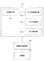
図3は、操作・表示部110の制御に関するブロック図である。ここでは操作・表示部110の制御に関する構成として、例えば画面表示部110a、タッチ位置検出部110b、タッチ判定部110c及びタッチ動作部110dが挙げられる。このうち画面表示部110aは、例えば液晶ディスプレイ及びそのドライバを含む構成単位である。液晶ディスプレイは、画像形成装置2の外装カバー表面で、ユーザから見えやすい位置に設けられている。 FIG. 3 is a block diagram regarding control of the operation /
タッチ位置検出部110bは、タッチ式パネル(入力装置)及びそのドライバを含む構成単位である。タッチ式パネルは、液晶ディスプレイの表示画面を覆う位置に設けられている。またドライバは、タッチ式パネルの検出方式(超音波式、赤外線式、接点式等)に合わせた検出動作を行う。タッチ式パネルの表面には二次元座標(X−Y座標)が仮想的に配置されており、タッチ操作がなされると、タッチ位置検出部110bはそれに応じた座標検出信号を出力する。 The touch
タッチ判定部110cは、タッチ位置検出部110bからの座標検出信号に基づいて、画面表示部110aに対して行われたユーザのタッチ操作位置(座標)を判定する機能を有する。タッチ判定部110cがタッチ操作位置を判定すると、その座標データがタッチ動作部110dに通知される。タッチ動作部110dは、受け取った座標データに基づいてタッチ操作に対応するファンクションを解析し、そのファンクションに基づく動作を実行する。 The
例えば、画面表示部110aの左上の位置に「用紙サイズ」と表示された操作ボタンが表示されており、この操作ボタンに対して「選択可能な用紙トレイを一覧表示する」というファンクションが登録されている場合を想定する。この場合、ユーザが「用紙サイズ」と表示された操作ボタンの有効領域(座標)に触れたことがタッチ判定部110cにより判定された場合、これを受けてタッチ動作部110dは画面表示部110aの表示内容を切り換え、液晶ディスプレイに選択可能な用紙トレイの一覧を表示させる処理を行う。なお、このような操作・表示部110における動作は画像形成制御部120により制御されている。 For example, an operation button displaying “paper size” is displayed at the upper left position of the
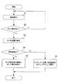
図4は、画像形成制御部120により実行されるプログラムの手順例を示したフローチャートである。画像形成制御部120(CPU)は、フローチャートの手順に従ってプログラムを実行する。以下、ステップS1〜ステップS5の内容について、順を追って説明する。 FIG. 4 is a flowchart illustrating a procedure example of a program executed by the image
ステップS1:画像形成制御部120は、画面表示部110aにより現在(カレント)の画面表示を行う。例えば、現在の画像形成装置2の状態が「待機中」であれば、画面表示部110aには各種の操作ボタンが適宜レイアウトされた初期画面が表示される。ここでいう「待機中」は、特にジョブを実行中ではなく、ユーザからのジョブを待ち受けた状態に相当する。このとき実際に表示するべき画像データは、例えば記憶部130のROMに格納されており、画像形成制御部120は、ROMから読み出した画像データに基づき、画面表示部110aのドライバに駆動信号を与える。 Step S1: The image
ステップS2:画像形成制御部120は、ユーザによるタッチ操作を待ち受ける。特にユーザのタッチ操作が行われなければ、画像形成制御部120はステップS1を繰り返し、画面表示を継続する。 Step S2: The image
ステップS3:ユーザによりタッチ操作が行われると、画像形成制御部120はそのときのタッチ位置(座標)を検出する。
ステップS4:先のステップS3で検出したタッチ位置(座標)に基づいて、画像形成制御部120は現在の表示画面上でいずれかの操作ボタンの有効領域(座標)がタッチされたか否かを判断する。Step S3: When a touch operation is performed by the user, the image
Step S4: Based on the touch position (coordinates) detected in the previous step S3, the image
ステップS5:画像形成制御部120は、先のステップS4でいずれかの操作ボタンの有効領域がタッチされたと判断した(Yes)場合、タッチ動作部110dに登録されている情報にしたがって動作を実行する。これにより、操作・表示部110では各操作ボタンに対応する動作(用紙サイズの選択、メニュー画面の表示更新等)が行われる。 Step S5: When the image
ステップS6:これに対し、先のステップS4で操作ボタンの有効領域がタッチされたと判断されなかった(No)場合、画像形成制御部120はタッチ操作がされている間、画面表示部110aにて有効領域外をグレイアウトして表示させる。 Step S6: On the other hand, if it is not determined in step S4 that the effective area of the operation button has been touched (No), the image
図5は、上記のプログラムの実行に伴う画面表示部110aの動作例を示した図である。現在の画像形成装置2の状態が「待機中」であれば、図5中(A)に示されているように、画面表示部110aには各種の操作ボタンB1〜B5が適宜レイアウトされた初期画面が表示されている。なお、ここでは特に示されていないが、これら操作ボタンB1〜B5の表示枠内には、例えば「用紙サイズ」、「倍率」、「両面印刷」、「パンチ穴開け」、「ステープルとじ」、「ソート」等の文字や絵記号等が合わせて表示されている。 FIG. 5 is a diagram illustrating an example of the operation of the
また、図5中(A)に示されているように、画面表示部110aには操作ボタンB1〜B5の他に、情報表示画像Pが表示されている。この情報表示画像Pは、画像形成装置2及び後処理装置4の外形を象った絵柄から構成されている。情報表示画像Pでは、例えば給紙部160の用紙切れや用紙ジャム、コンタクトガラス上の原稿の取り忘れ等の情報が各位置に対応して表示されるものとなっている。Further, as shown in FIG. 5A, in addition to the operation buttons B1 to B5, an information display image P is displayed on the
いずれにしても、図5中(A)に示される画面表示の例では、ユーザによるタッチ操作は操作ボタンB1〜B5の表示枠内でのみ有効となる。ユーザが操作ボタンB1〜B5のいずれかの有効領域をタッチ操作した場合、画像形成制御部120によりステップS5が実行され、操作ボタンB1〜B5にそれぞれ対応した動作(ファンクション)が実行されることになる。 In any case, in the example of the screen display shown in FIG. 5A, the touch operation by the user is valid only within the display frame of the operation buttons B1 to B5. When the user touches any one of the effective areas of the operation buttons B1 to B5, step S5 is executed by the image
これに対し、操作ボタンB1〜B5の表示枠外をユーザがタッチ操作した場合は、各操作ボタンB1〜B5に対応する動作(ファンクション)は実行されない。その代わり本実施形態では、図5中(B)に示されているように、操作ボタンB1〜B5の表示枠外(有効領域外)がグレイアウトして表示される(ステップS6)。したがって、このようなグレイアウト表示との対比により、操作ボタンB1〜B5の部分における表示の明度が相対的に高くなり、それまでより一段と強調表示されるため、結果的にユーザからの視認性を向上させることができる。 On the other hand, when the user performs a touch operation outside the display frame of the operation buttons B1 to B5, operations (functions) corresponding to the operation buttons B1 to B5 are not executed. Instead, in this embodiment, as shown in FIG. 5B, the operation buttons B1 to B5 outside the display frame (outside the effective area) are grayed out and displayed (step S6). Therefore, the brightness of the display in the operation buttons B1 to B5 becomes relatively high by contrast with the gray-out display as described above, so that the display is more emphasized than before. Can be improved.
このため、ユーザが初期画面(図5中(A))を一見しただけでは操作ボタンB1〜B5の存在を完全に認識できなかった場合であっても、漠然と画面表示部110aのどこかにユーザが触れると、それが操作ボタンB1〜B5の表示枠外であった場合、上記のようなグレイアウト表示が行われることで操作ボタンB1〜B5の存在を際立たせることができる。この後、ユーザはあらためて操作ボタンB1〜B5のいずれかをタッチ操作することで、各操作ボタンB1〜B5に対応する動作を指示することができる。 For this reason, even if the user cannot completely recognize the presence of the operation buttons B1 to B5 just by looking at the initial screen ((A) in FIG. 5), the user vaguely somewhere on the
なお、ここでは非有効領域をグレイアウト表示(明度を低下)することで、相対的に操作ボタンB1〜B5(有効領域)を一段と強調表示させているが、画面表示部110a内での操作ボタンB1〜B5(有効領域)とその表示枠外(非有効領域)との相対的な関係を利用することで、各種の強調表示を行うことが可能である。以下に、いくつか例を挙げる。 Here, the operation buttons B1 to B5 (effective areas) are relatively highlighted by graying out the ineffective area (decreasing the brightness), but the operation buttons in the
(1)操作ボタンB1〜B5を目立たせる表示態様
操作ボタンB1〜B5の表示枠内での表示態様を変化させることで、初期画面での表示態様に比較して操作ボタンB1〜B5の部分を一段と強調表示する。例えば、操作ボタンB1〜B5を強調表示する例として反転表示、ハイライト表示等により色相、明度、彩度を変化させる(高くする)もの、もしくは色調を変化させることで色相、明度、彩度を変化させる(高くする)もの等が挙げられる。その他、操作ボタンB1〜B5を点滅させたり、動画を用いて表示態様を変化させることで強調表示を行ってもよい。なお、このような強調表示は操作ボタンB1〜B5(有効領域)の全域で行ってもよいし、その一部分だけで行ってもよい。例えば、操作ボタンB1〜B5の縁取り(枠)だけを強調表示してもよいし、その文字だけを強調表示してもよい。この場合、縁取りや文字の部分の色相、明度、彩度を変化させて(高くして)強調表示するほか、縁取りを太枠にしたり、文字を太字にしたりすることで強調表示してもよい。(1) Display mode in which the operation buttons B1 to B5 are conspicuous By changing the display mode in the display frame of the operation buttons B1 to B5, the operation buttons B1 to B5 are compared with the display mode on the initial screen. Highlight more. For example, as an example of highlighting the operation buttons B1 to B5, the hue, brightness, and saturation are changed (increased) by reverse display, highlight display, etc., or the hue, brightness, and saturation are changed by changing the hue. What is changed (increased) is mentioned. In addition, highlighting may be performed by blinking the operation buttons B1 to B5 or changing the display mode using a moving image. Such highlighting may be performed on the entire operation buttons B1 to B5 (effective area) or only on a part thereof. For example, only the borders (frames) of the operation buttons B1 to B5 may be highlighted, or only the characters may be highlighted. In this case, in addition to highlighting by changing (increasing) the hue, brightness, and saturation of the border or character portion, it may be highlighted by making the border bold or making the character bold. .
(2)非有効領域を目立たなくする表示態様
先のグレイアウト表示の例で挙げたほか、非有効領域の表示態様を変化(明度や彩度の低下、色調の変化等)させることで、初期画面での表示態様に比較して非有効領域を一段と目立たなくする。(2) Display mode that makes ineffective areas inconspicuous In addition to the gray display example given above, the display mode of ineffective areas can be changed by changing the display mode (decrease in brightness, saturation, color tone, etc.) Compared with the display mode on the screen, the ineffective area is made less noticeable.
(3)上記(1)の表示態様と(2)の表示態様との併用
操作ボタンB1〜B5の表示枠内での表示態様を変化させるとともに、合わせて非有効領域の表示態様を変化させることで、初期画面での表示態様に比較して操作ボタンB1〜B5の部分を一段と強調表示するとともに、非有効領域を一段と目立たなくする。(3) Combined use of the display mode of (1) and the display mode of (2) Changing the display mode of the operation buttons B1 to B5 within the display frame, and changing the display mode of the ineffective area at the same time Thus, compared with the display mode on the initial screen, the portions of the operation buttons B1 to B5 are highlighted more and the ineffective area is made more inconspicuous.
いずれにしても、画面表示部110a内では相対的に操作ボタンB1〜B5(有効領域)の部分がそれまでよりも一段と強調表示されることになるため、ユーザは操作ボタンB1〜B5の存在を容易に視認することができ、それによって次のタッチ操作を容易に行うことができる。 In any case, since the portions of the operation buttons B1 to B5 (effective area) are relatively highlighted in the
この点、初期画面の段階で最初から操作ボタンB1〜B5の部分を極めて強調表示(際立った色調表示、常時点滅表示)しておくという手法もあるが、画面表示部110a全体のカラーバランスやデザインの調和、ユーザの操作性に鑑みると(例えば、はじめから複数の操作ボタンB1〜B5がチカチカと点滅していると、ユーザが操作しづらいと考えられる。)、初期画面としてそのような手法はあまり好ましくない。 In this regard, there is a method of highlighting the operation buttons B1 to B5 from the beginning at the initial screen stage (prominent color tone display, always flashing display), but the color balance and design of the entire
本実施形態では、初期画面の段階では操作ボタンB1〜B5の部分を枠で囲む程度の識別性を持たせることでユーザの操作性を損なわないようにしている。その上で、ユーザが非有効領域をタッチ操作した場合には、それまでよりも一段と操作ボタンB1〜B5の部分を強調表示することで視覚的な識別性を高め、次に行われるユーザのタッチ操作を補助することができる。 In the present embodiment, at the initial screen stage, the operability of the user is not impaired by giving the discriminability to the extent that the operation buttons B1 to B5 are surrounded by a frame. In addition, when the user performs a touch operation on the ineffective area, the visual discrimination is enhanced by highlighting the portions of the operation buttons B1 to B5 more than before, and the next user touch is performed. Operation can be assisted.
また、実際の操作ボタンB1〜B5の配置については図5に例示されるものに限られない。特に本実施形態では、初期状態で操作ボタンB1〜B5を極端に目立たせるように配置していなくても、ユーザが非有効領域に触れた場合に強調表示することで、ユーザに操作ボタンB1〜B5の位置を視覚的に気付かせ易くしている。このため、従来の配置にとらわれず操作ボタンB1〜B5等のレイアウトを自由に組み替えることができ、それによって操作・表示部110全体としてのデザイン性を向上することができる。 Further, the actual arrangement of the operation buttons B1 to B5 is not limited to that illustrated in FIG. In particular, in this embodiment, even if the operation buttons B1 to B5 are not arranged so as to be extremely conspicuous in the initial state, the operation buttons B1 to B1 are displayed to the user by highlighting when the user touches the ineffective area. The position of B5 is visually noticeable. For this reason, the layout of the operation buttons B1 to B5 and the like can be freely rearranged regardless of the conventional arrangement, thereby improving the design of the operation /
なお、図4のフローチャートではユーザが非有効領域に触れている間に操作ボタンB1〜B5の強調表示を行う(ステップS6)こととしているが、ステップS6に続いてタイマをカウントするステップを追加し、ここで一定時間(例えば1〜2秒程度)が経過するまでステップS6がループして繰り返される手順をプログラムに組み込んでもよい。この場合、ユーザが非有効領域から指を離した後も一定時間(1〜2秒程度)にわたり強調表示が継続されるため、その間にユーザが次の操作に移りやすくなる。 In the flowchart of FIG. 4, the operation buttons B1 to B5 are highlighted while the user is touching the ineffective area (step S6), but a step of counting a timer is added following step S6. Here, a procedure in which step S6 is looped and repeated until a certain time (for example, about 1 to 2 seconds) elapses may be incorporated in the program. In this case, since the highlighting is continued for a certain time (about 1 to 2 seconds) even after the user lifts the finger from the ineffective area, the user can easily move to the next operation during that time.
また一実施形態では、ステップS6で全ての操作ボタンB1〜B5を一様に強調表示させているが、その時点で操作が有効となる一部の操作ボタンのみを強調表示させてもよい。この場合、ユーザが無関係な操作ボタンに目を引かれることがないので、より操作性が高まる。 In one embodiment, all the operation buttons B1 to B5 are uniformly highlighted in step S6. However, only a part of the operation buttons that are effective at that time may be highlighted. In this case, since the user is not attracted by irrelevant operation buttons, the operability is further improved.
あるいは、操作ボタンB1〜B5のそれぞれについてユーザがタッチ操作を行った頻度を記憶部130に記録しておき、なかでも比較的に操作頻度が高い操作ボタンのみを優先的に強調表示してもよい。この場合、ユーザがあまり操作しない操作ボタンに目を引かれることがないので、同じく操作性が高まる。 Alternatively, the frequency at which the user performs the touch operation for each of the operation buttons B1 to B5 may be recorded in the
本発明は一実施形態に制約されることなく、各種の電子機器に採用することができる。一実施形態で挙げた画像形成装置2の他に、タッチ式パネルを用いて操作を受け付ける電子機器であれば、例えばパーソナルコンピュータや自動券売機、自動販売機、現金自動預払機(ATM)等の他、リモコンのように操作だけを受け付け、その操作信号を送って本体に動作を実行させるものであっても本発明を適用することができる。 The present invention is not limited to one embodiment and can be employed in various electronic devices. In addition to the
その他、一実施形態で挙げた各種の部材や駆動部品はいずれも好ましい例示であり、これらは適宜変形して実施することが可能である。 In addition, the various members and driving components mentioned in the embodiment are all preferable examples, and these can be appropriately modified and implemented.
2 画像形成装置
110 操作・表示部
120 画像形成制御部
130 記憶部
2
Claims (12)
Translated fromJapanese前記画面表示手段の画面に対する使用者の接触を伴うタッチ操作を受け付けるタッチ入力手段と、
前記タッチ入力手段により前記タッチ操作が受け付けられたとき、そのタッチ操作がなされた前記画面内でのタッチ位置を検出するタッチ位置検出手段と、
前記タッチ位置検出手段により検出されたタッチ位置が前記画面内で前記非有効領域に対応していると判定された場合、前記非有効領域での明度及び彩度の少なくとも一方を低下させて前記非有効領域の表示態様を変化させることにより、前記画面内で前記非有効領域よりも前記有効領域を強調して表示する表示態様変化手段と
を備えたことを特徴とする電子機器。A screen display means for forming an effective area in which operation information about an operation to be performed by a user is displayed in a predetermined screen, and displaying the effective area and the other ineffective area separately in the screen;
Touch input means for accepting a touch operation involving a user's contact with the screen of the screen display means;
When the touch operation is accepted by the touch input means, a touch position detection means for detecting a touch position in the screen where the touch operation is performed;
When it is determined that the touch position detected by the touch position detection unit corresponds to the ineffective area in the screen, atleast one of brightness and saturation in the ineffective area is reduced to reduce the non-effective area. An electronic apparatuscomprising: display mode changing meansfor displaying the effective area in an emphasized manner over the non-effective area by changing the display mode of the effective area .
前記画面表示手段の画面に対する使用者の接触を伴うタッチ操作を受け付けるタッチ入力手段と、
前記タッチ入力手段により前記タッチ操作が受け付けられたとき、そのタッチ操作がなされた前記画面内でのタッチ位置を検出するタッチ位置検出手段と、
前記タッチ位置検出手段により検出されたタッチ位置が前記画面内で前記有効領域に対応していると判定された場合、前記有効領域に表示された操作情報に基づく動作を実行する動作実行手段と、
前記タッチ位置検出手段により検出されたタッチ位置が前記画面内で前記非有効領域に対応していると判定された場合、前記非有効領域での明度及び彩度の少なくとも一方を低下させて前記非有効領域の表示態様を変化させることにより、前記画面内で前記非有効領域よりも前記有効領域を強調して表示する表示態様変化手段と
を備えたことを特徴とする電子機器。A screen display means for forming an effective area in which operation information about an operation to be performed by a user is displayed in a predetermined screen, and displaying the effective area and the other ineffective area separately in the screen;
Touch input means for accepting a touch operation involving a user's contact with the screen of the screen display means;
When the touch operation is accepted by the touch input means, a touch position detection means for detecting a touch position in the screen where the touch operation is performed;
An action executing means for executing an action based on the operation information displayed in the effective area when it is determined that the touch position detected by the touch position detecting means corresponds to the effective area in the screen;
When it is determined that the touch position detected by the touch position detection unit corresponds to the ineffective area in the screen, atleast one of brightness and saturation in the ineffective area is reduced to reduce the non-effective area. An electronic apparatuscomprising: display mode changing meansfor displaying the effective area in an emphasized manner over the non-effective area by changing the display mode of the effective area .
前記表示態様変化手段は、
前記非有効領域での明度を初期画面より低下させて前記非有効領域をグレイアウト表示することにより、前記画面内で前記非有効領域よりも前記有効領域を強調して表示することを特徴とする電子機器。The electronic device according to claim 1 or 2,
The display mode changing means includes
By thelightness of the initial screen grayed the non-effective area is lowered than in thenon-active area, and displaying to emphasize the effective area than the non-active area in the screen Electronics.
前記画面表示手段は、
前記画面内に前記有効領域として複数の前記操作情報に対応した複数の操作ボタンを表示し、
前記表示態様変化手段は、
前記タッチ位置検出手段により検出されたタッチ位置が前記画面内で前記非有効領域に対応していると判定された時点で操作が有効となる一部の前記操作ボタンのみを強調して表示することを特徴とする電子機器。In the electronic device inanyone of Claim1 to 3,
The screen display means includes
Displaying a plurality of operation buttons corresponding to a plurality of the operation information as the effective area in the screen;
The display mode changing means includes
Only a part of the operation buttons whose operations are enabled when the touch position detected by the touch position detection means is determined to correspond to the ineffective area in the screen are highlighted. Electronic equipment characterized by
前記画面表示手段により前記画面内に前記有効領域として複数の前記操作情報に対応した複数の操作ボタンが表示されている場合、複数の前記操作ボタンのそれぞれについてタッチ操作が行われた頻度を記録する記憶部を備え、
前記表示態様変化手段は、
複数ある前記操作ボタンのなかでも、前記記憶部に記録された頻度が比較的に高い前記操作ボタンのみを優先的に強調して表示することを特徴とする電子機器。In the electronic device inanyone of Claim1 to 3,
When a plurality of operation buttons corresponding to a plurality of the operation information are displayed as the effective area in the screen by the screen display means, the frequency of the touch operation for each of the plurality of operation buttons is recorded. A storage unit,
The display mode changing means includes
An electronic apparatus characterizedby preferentially highlighting and displaying only the operation buttons recorded in the storage unit that are relatively high among the plurality of operation buttons .
前記表示態様変化手段は、
前記非有効領域での明度及び彩度の少なくとも一方を低下させ、且つ前記有効領域での明度及び彩度の少なくとも一方を高くすることでそれぞれの表示態様を変化させることにより、前記非有効領域よりも前記有効領域を強調して表示することを特徴とする電子機器。The electronic device according to anyone of claims1 to 5,
The display mode changing means includes
By reducing at least one of lightness and saturation in thenon-effective area and changing each display mode by increasing at least one of lightness and saturation in theeffective area, Also , the electronic device is characterizedin that the effective area is highlighted .
前記表示態様変化手段は、
前記タッチ位置検出手段により検出されたタッチ位置が前記画面内で前記非有効領域に対応していると判定された場合、前記タッチ操作が継続している期間内で前記非有効領域の表示態様を変化させることを特徴とする電子機器。In the electronic device in any one of Claim 1 to 6,
The display mode changing means includes
If it has been touched position detected by the touch position detecting means is determined to correspond to the non-effective area within the screen,the display mode ofthe non-active area within a period in which the touch operation is continuing An electronic device characterized by being changed.
前記表示態様変化手段は、
前記タッチ位置検出手段により検出されたタッチ位置が前記画面内で前記非有効領域に対応していると判定された場合、前記タッチ操作が解除された後に一定期間が経過するまでの期間にわたり前記非有効領域の表示態様を変化させることを特徴とする電子機器。In the electronic device in any one of Claim 1 to 6,
The display mode changing means includes
If has been touched position detected by the touch position detecting means is determined to correspond to the non-effective area within the screen,the non-over period until after a certain period of time after the touch operation has been canceled An electronic apparatus characterizedby changing a display modeof an effective area.
前記表示態様変化手段は、
前記有効領域に表示される前記操作情報の表示態様のみを変化させることで前記非有効領域の表示態様を変化させることを特徴とする電子機器。In the electronic device in any one of Claim 1 to 8,
The display mode changing means includes
An electronic apparatus,wherein the display modeof the ineffective area is changed by changing only the display mode of the operation information displayed in the effective area.
前記表示態様変化手段は、
前記有効領域に表示される前記操作情報の表示態様を保持しつつ、前記操作情報以外の表示態様のみを変化させることで前記非有効領域の表示態様を変化させることを特徴とする電子機器。In the electronic device in any one of Claim 1 to 8,
The display mode changing means includes
An electronic apparatus,wherein the display modeof the ineffective area is changed by changing only the display mode other than the operation information while maintaining the display mode of the operation information displayed in the effective area.
前記表示画面内に使用者が行うべき操作についての操作情報が表示される有効領域を形成し、前記画面内で前記有効領域とそれ以外の非有効領域とを区別して表示する手順と、
前記表示画面に対する使用者の接触を伴うタッチ操作を受け付ける手順と、
前記表示画面に対するタッチ操作が受け付けられたとき、そのタッチ操作がなされた前記表示画面内でのタッチ位置を検出する手順と、
前記検出されたタッチ位置が前記表示画面内で前記有効領域ではなく前記非有効領域に対応していると判定した場合、前記非有効領域での明度及び彩度の少なくとも一方を低下させて前記非有効領域の表示態様を変化させることにより、前記画面内で前記非有効領域よりも前記有効領域を強調して表示する手順と
を実行させるプログラム。In an electronic device computer having a predetermined display screen,
A procedure for forming an effective area in which operation information about an operation to be performed by the user is displayed in the display screen, and displaying the effective area and the other ineffective area separately in the screen;
A procedure for accepting a touch operation involving a user's contact with the display screen;
When a touch operation on the display screen is accepted, a procedure for detecting a touch position in the display screen where the touch operation is performed;
When it is determined that the detected touch position corresponds to the non-effective area instead of the effective area in the display screen, atleast one of brightness and saturation in the non-effective area is reduced to reduce the non-effective area. The program which performsthe procedurewhich emphasizes and displays the said effective area rather than the said non-effective area in the said screen by changing the display mode of an effective area .
前記表示画面内に使用者が行うべき操作についての操作情報が表示される有効領域を形成し、前記画面内で前記有効領域とそれ以外の非有効領域とを区別して表示する手順と、
前記表示画面に対する使用者の接触を伴うタッチ操作を受け付ける手順と、
前記表示画面に対するタッチ操作が受け付けられたとき、そのタッチ操作がなされた前記表示画面内でのタッチ位置を検出する手順と、
前記検出されたタッチ位置が前記表示画面内で前記有効領域に対応しているか否かを判定し、前記有効領域に対応していると判定した場合、前記有効領域に表示された操作情報に基づく動作を実行する手順と、
前記検出されたタッチ位置が前記表示画面内で前記有効領域ではなく前記非有効領域に対応していると判定した場合、前記非有効領域での明度及び彩度の少なくとも一方を低下させて前記非有効領域の表示態様を変化させることにより、前記画面内で前記非有効領域よりも前記有効領域を強調して表示する手順と
を実行させるプログラム。In an electronic device computer having a predetermined display screen,
A procedure for forming an effective area in which operation information about an operation to be performed by the user is displayed in the display screen, and displaying the effective area and the other ineffective area separately in the screen;
A procedure for accepting a touch operation involving a user's contact with the display screen;
When a touch operation on the display screen is accepted, a procedure for detecting a touch position in the display screen where the touch operation is performed;
It is determined whether or not the detected touch position corresponds to the effective area in the display screen, and when it is determined that the detected touch position corresponds to the effective area, based on the operation information displayed in the effective area The steps to perform the action;
When it is determined that the detected touch position corresponds to the non-effective area instead of the effective area in the display screen, atleast one of brightness and saturation in the non-effective area is reduced to reduce the non-effective area. The program which performsthe procedurewhich emphasizes and displays the said effective area rather than the said non-effective area in the said screen by changing the display mode of an effective area .
Priority Applications (2)
| Application Number | Priority Date | Filing Date | Title |
|---|---|---|---|
| JP2006190454AJP4764274B2 (en) | 2006-07-11 | 2006-07-11 | Electronic device and program |
| US11/827,204US7969424B2 (en) | 2006-07-11 | 2007-07-11 | Electronic device, recording medium and method |
Applications Claiming Priority (1)
| Application Number | Priority Date | Filing Date | Title |
|---|---|---|---|
| JP2006190454AJP4764274B2 (en) | 2006-07-11 | 2006-07-11 | Electronic device and program |
Publications (2)
| Publication Number | Publication Date |
|---|---|
| JP2008021000A JP2008021000A (en) | 2008-01-31 |
| JP4764274B2true JP4764274B2 (en) | 2011-08-31 |
Family
ID=38948779
Family Applications (1)
| Application Number | Title | Priority Date | Filing Date |
|---|---|---|---|
| JP2006190454AExpired - Fee RelatedJP4764274B2 (en) | 2006-07-11 | 2006-07-11 | Electronic device and program |
Country Status (2)
| Country | Link |
|---|---|
| US (1) | US7969424B2 (en) |
| JP (1) | JP4764274B2 (en) |
Cited By (2)
| Publication number | Priority date | Publication date | Assignee | Title |
|---|---|---|---|---|
| KR20190123148A (en)* | 2018-04-23 | 2019-10-31 | 현대자동차주식회사 | Input switch and operation method thereof |
| US10510097B2 (en) | 2011-10-19 | 2019-12-17 | Firstface Co., Ltd. | Activating display and performing additional function in mobile terminal with one-time user input |
Families Citing this family (10)
| Publication number | Priority date | Publication date | Assignee | Title |
|---|---|---|---|---|
| KR101646922B1 (en) | 2009-05-19 | 2016-08-23 | 삼성전자 주식회사 | Operation Method of associated with a communication function And Portable Device supporting the same |
| JP5937435B2 (en) | 2012-06-27 | 2016-06-22 | 京セラ株式会社 | Portable terminal, operation prohibited area control program, and operation prohibited area control method |
| KR20150014679A (en)* | 2013-07-30 | 2015-02-09 | 삼성전자주식회사 | Display apparatus and control method thereof |
| US20170038904A1 (en)* | 2014-04-23 | 2017-02-09 | Sharp Kabushiki Kaisha | Input device |
| JP2016062259A (en)* | 2014-09-17 | 2016-04-25 | Jr東日本メカトロニクス株式会社 | Information processing device, information processing method, and program |
| US10144288B2 (en) | 2016-03-31 | 2018-12-04 | Denso International America, Inc. | LCD display with highlighting |
| US10332303B2 (en) | 2016-04-26 | 2019-06-25 | Imagination Technologies Limited | Dedicated ray memory for ray tracing in graphics systems |
| JP6727036B2 (en)* | 2016-06-01 | 2020-07-22 | キヤノン株式会社 | Electronic device, control method thereof, program, and recording medium |
| JP7419051B2 (en)* | 2019-12-17 | 2024-01-22 | キヤノン株式会社 | Electronic devices, their control methods, programs and storage media |
| JP2023131943A (en)* | 2022-03-10 | 2023-09-22 | セイコーエプソン株式会社 | Image forming device, jig to be used in operating image forming device, and electronic instrument |
Family Cites Families (6)
| Publication number | Priority date | Publication date | Assignee | Title |
|---|---|---|---|---|
| JP3427519B2 (en) | 1994-11-07 | 2003-07-22 | 富士ゼロックス株式会社 | Recording device |
| US5790114A (en)* | 1996-10-04 | 1998-08-04 | Microtouch Systems, Inc. | Electronic whiteboard with multi-functional user interface |
| KR100595922B1 (en)* | 1998-01-26 | 2006-07-05 | 웨인 웨스터만 | Method and apparatus for integrating manual input |
| JP2000020200A (en)* | 1998-07-03 | 2000-01-21 | Mitsubishi Electric Corp | User interface device |
| JP4500485B2 (en)* | 2002-08-28 | 2010-07-14 | 株式会社日立製作所 | Display device with touch panel |
| US7821501B2 (en)* | 2005-12-14 | 2010-10-26 | Sigmatel, Inc. | Touch screen driver and methods for use therewith |
- 2006
- 2006-07-11JPJP2006190454Apatent/JP4764274B2/ennot_activeExpired - Fee Related
- 2007
- 2007-07-11USUS11/827,204patent/US7969424B2/ennot_activeExpired - Fee Related
Cited By (6)
| Publication number | Priority date | Publication date | Assignee | Title |
|---|---|---|---|---|
| US10510097B2 (en) | 2011-10-19 | 2019-12-17 | Firstface Co., Ltd. | Activating display and performing additional function in mobile terminal with one-time user input |
| US10896442B2 (en) | 2011-10-19 | 2021-01-19 | Firstface Co., Ltd. | Activating display and performing additional function in mobile terminal with one-time user input |
| US11551263B2 (en) | 2011-10-19 | 2023-01-10 | Firstface Co., Ltd. | Activating display and performing additional function in mobile terminal with one-time user input |
| US12159299B2 (en) | 2011-10-19 | 2024-12-03 | Firstface Co., Ltd. | Activating display and performing additional function in mobile terminal with one-time user input |
| KR20190123148A (en)* | 2018-04-23 | 2019-10-31 | 현대자동차주식회사 | Input switch and operation method thereof |
| KR102575145B1 (en)* | 2018-04-23 | 2023-09-06 | 현대자동차주식회사 | Input switch and operation method thereof |
Also Published As
| Publication number | Publication date |
|---|---|
| US7969424B2 (en) | 2011-06-28 |
| US20080012836A1 (en) | 2008-01-17 |
| JP2008021000A (en) | 2008-01-31 |
Similar Documents
| Publication | Publication Date | Title |
|---|---|---|
| JP4764274B2 (en) | Electronic device and program | |
| US9152261B2 (en) | Display input device, and image forming apparatus including touch panel portion | |
| JP4690272B2 (en) | Electronic device and program | |
| JP5614149B2 (en) | Image forming system | |
| JP5693408B2 (en) | Operating device | |
| JP2008012755A (en) | Image forming system and image formation method | |
| US7417758B2 (en) | Image forming apparatus, and sheet placing direction instructing method | |
| JP6565354B2 (en) | Sheet processing apparatus, image forming apparatus, image forming system, and printer tool of sheet processing system | |
| CN103085504B (en) | Printer, printing control method, and computer-readable recording medium | |
| JP5001613B2 (en) | Image forming apparatus | |
| JP2013014393A (en) | Image forming device | |
| JP2009025858A (en) | Electronic apparatus | |
| US7522855B2 (en) | Image forming system and image forming apparatus | |
| EP3521936B1 (en) | Display input device, image forming apparatus, control method for display input device | |
| JP5084440B2 (en) | Sheet stacking apparatus and image forming system | |
| JP5545241B2 (en) | Image forming system and image forming apparatus | |
| JP5814875B2 (en) | Image forming apparatus | |
| JP2004093988A (en) | Image forming device | |
| JP2008012756A (en) | Image forming system and image formation method | |
| JP2003104575A (en) | Image forming device | |
| JP2007017704A (en) | Image forming apparatus | |
| JP2012071445A (en) | Image forming apparatus and image forming system | |
| JP2006349927A (en) | Image forming system | |
| JP4369414B2 (en) | Image forming apparatus and saddle stitch control program | |
| JP2006085462A (en) | Image forming system and image forming method |
Legal Events
| Date | Code | Title | Description |
|---|---|---|---|
| A621 | Written request for application examination | Free format text:JAPANESE INTERMEDIATE CODE: A621 Effective date:20090625 | |
| A977 | Report on retrieval | Free format text:JAPANESE INTERMEDIATE CODE: A971007 Effective date:20110118 | |
| A131 | Notification of reasons for refusal | Free format text:JAPANESE INTERMEDIATE CODE: A131 Effective date:20110125 | |
| A521 | Request for written amendment filed | Free format text:JAPANESE INTERMEDIATE CODE: A523 Effective date:20110325 | |
| TRDD | Decision of grant or rejection written | ||
| A01 | Written decision to grant a patent or to grant a registration (utility model) | Free format text:JAPANESE INTERMEDIATE CODE: A01 Effective date:20110517 | |
| A01 | Written decision to grant a patent or to grant a registration (utility model) | Free format text:JAPANESE INTERMEDIATE CODE: A01 | |
| A61 | First payment of annual fees (during grant procedure) | Free format text:JAPANESE INTERMEDIATE CODE: A61 Effective date:20110610 | |
| FPAY | Renewal fee payment (event date is renewal date of database) | Free format text:PAYMENT UNTIL: 20140617 Year of fee payment:3 | |
| R150 | Certificate of patent or registration of utility model | Free format text:JAPANESE INTERMEDIATE CODE: R150 Ref document number:4764274 Country of ref document:JP Free format text:JAPANESE INTERMEDIATE CODE: R150 | |
| FPAY | Renewal fee payment (event date is renewal date of database) | Free format text:PAYMENT UNTIL: 20140617 Year of fee payment:3 | |
| S533 | Written request for registration of change of name | Free format text:JAPANESE INTERMEDIATE CODE: R313533 | |
| FPAY | Renewal fee payment (event date is renewal date of database) | Free format text:PAYMENT UNTIL: 20140617 Year of fee payment:3 | |
| R350 | Written notification of registration of transfer | Free format text:JAPANESE INTERMEDIATE CODE: R350 | |
| LAPS | Cancellation because of no payment of annual fees |