JP4762647B2 - Polishing apparatus and polishing method - Google Patents
Polishing apparatus and polishing methodDownload PDFInfo
- Publication number
- JP4762647B2 JP4762647B2JP2005247252AJP2005247252AJP4762647B2JP 4762647 B2JP4762647 B2JP 4762647B2JP 2005247252 AJP2005247252 AJP 2005247252AJP 2005247252 AJP2005247252 AJP 2005247252AJP 4762647 B2JP4762647 B2JP 4762647B2
- Authority
- JP
- Japan
- Prior art keywords
- polishing
- pressure
- roll
- amount
- support
- Prior art date
- Legal status (The legal status is an assumption and is not a legal conclusion. Google has not performed a legal analysis and makes no representation as to the accuracy of the status listed.)
- Expired - Lifetime
Links
Images


Landscapes
- Mechanical Treatment Of Semiconductor (AREA)
- Finish Polishing, Edge Sharpening, And Grinding By Specific Grinding Devices (AREA)
Description
Translated fromJapanese本発明は、光学部品、機械部品、セラミックス及び金属等を研磨する研磨装置ならびに研磨方法に関し、特に、半導体デバイスが形成されたウェーハ等の研磨対象物を平坦且つ鏡面状に研磨するのに好適な研磨装置及び研磨方法に関する。 The present invention relates to a polishing apparatus and a polishing method for polishing optical parts, mechanical parts, ceramics, metals, and the like, and particularly suitable for polishing a polishing object such as a wafer on which a semiconductor device is formed flat and mirror-like. The present invention relates to a polishing apparatus and a polishing method.
近年、半導体デバイスの高集積化が進むにつれて、回路の配線が微細化し、集積される半導体デバイスの寸法もより微細化されつつある。そこで、ウェーハの表面に形成された被膜を研磨により除去して、表面を平坦化する工程が必要となり、この平坦化法の手法として、化学機械研磨(CMP)装置により研磨することが行われている。化学機械研磨装置は、研磨布やパッド等の研磨部材と、研磨対象物を保持するためのトップリングやチャック等の保持部材とを備え、ウェーハ等の研磨対象物の研磨対象面を研磨部材に押し当て、両者の間に砥液、薬液、スラリー、純水等の研磨助剤を供給しつつ相対運動させることにより、研磨対象物の表面を平坦かつ鏡面状に研磨するものである。 In recent years, with the progress of higher integration of semiconductor devices, circuit wiring has become finer, and the dimensions of integrated semiconductor devices have also become finer. Therefore, it is necessary to remove the film formed on the surface of the wafer by polishing and to flatten the surface. As a method of this flattening method, polishing is performed by a chemical mechanical polishing (CMP) apparatus. Yes. The chemical mechanical polishing apparatus includes a polishing member such as a polishing cloth or a pad, and a holding member such as a top ring or a chuck for holding the polishing target, and the polishing target surface of the polishing target such as a wafer is used as a polishing member. The surface of the object to be polished is polished flat and mirror-like by pressing and relatively moving while supplying a polishing aid such as an abrasive, chemical, slurry, or pure water between them.
この種の化学機械研磨装置においては、研磨部材は主に円盤型又は円環型の形状を有しており、研磨部材と研磨対象物との大小関係により、大径研磨部材回転型、小径研磨部材回転走査型などに分類できる。大径研磨部材回転型の研磨装置は、研磨対象物をトップリングにより研磨対象面を下側にして即ちフェイスダウンで保持して回転させながら、研磨対象物よりも大きな研磨部材が備えられたターンテーブルに押し当てて研磨対象物を研磨する。研磨部材は一般的にはターンテーブルにより回転する。一方、小径研磨部材回転走査型の研磨装置は、研磨対象物をチャックにより研磨対象面を上側にして、即ちフェイスアップで保持して回転させながら、研磨対象物よりも小さな研磨部材を研磨対象面に押し当てて回転させつつ走査させて研磨対象物を研磨する。 In this type of chemical mechanical polishing apparatus, the polishing member mainly has a disk shape or an annular shape, and depending on the size relationship between the polishing member and the object to be polished, the large diameter polishing member rotating type, the small diameter polishing is performed. It can be classified as a member rotation scanning type. The large-diameter polishing member rotating type polishing apparatus has a turn provided with a polishing member larger than the polishing object while rotating the polishing object with the top ring held with the polishing target surface facing down, that is, face-down. The object to be polished is polished against the table. The polishing member is generally rotated by a turntable. On the other hand, the small-diameter polishing member rotation scanning type polishing apparatus holds a polishing object smaller than the polishing object surface while holding the surface to be polished with a chuck, that is, holding the face up and rotating it. The object to be polished is polished by being pressed against and rotated while being rotated.
上記のいずれの研磨装置においても、研磨対象物から研磨部材の一部が一時的に又は常時はみ出る。この研磨部材のはみ出しにより研磨対象物のエッジ周辺に過大な研磨圧力が加わり、研磨対象物のエッジ周辺で平坦度が悪くなる。このため、半導体デバイスが形成されたウェーハにおいては半導体デバイスの歩留りが悪化する。これはウェーハの外周部ほど多くの半導体デバイスが存在するためである。したがって、半導体デバイス・メーカ等が定めたエッジ・イクスクルージョンに十分対応できる様に、できるだけエッジの近くにまで平坦度のよい領域を広げることが研磨装置に与えられた課題の一つである。 In any of the above polishing apparatuses, a part of the polishing member protrudes temporarily or constantly from the object to be polished. Due to the protrusion of the polishing member, an excessive polishing pressure is applied around the edge of the object to be polished, and the flatness is deteriorated around the edge of the object to be polished. For this reason, the yield of semiconductor devices deteriorates in a wafer on which semiconductor devices are formed. This is because there are more semiconductor devices on the outer periphery of the wafer. Accordingly, one of the problems given to the polishing apparatus is to widen the region with good flatness as close as possible to the edge so that it can sufficiently cope with the edge exclusion defined by the semiconductor device manufacturer.
上述の過大な研磨圧力は、研磨部材のうちの研磨対象物からはみ出して開放状態になっていた部分が研磨部材と研磨対象物との相対運動により研磨対象物に作用させる圧力、即ち、研磨部材と研磨対象物とを接触させながら移動する際の押付け圧力によって急激に圧迫されるために生じることが知られている。この様な現象はリバウンドと呼ばれている。リバウンドは、研磨対象物の方へ圧迫されていた研磨部材が研磨対象物からはみ出して押付け圧力から開放される場合にも生じる。 The excessive polishing pressure described above is the pressure at which the portion of the polishing member that has been released from the polishing object and is in the open state acts on the polishing object by the relative movement of the polishing member and the polishing object, that is, the polishing member. It is known that it is caused by abrupt pressure caused by the pressing pressure when moving while contacting the object to be polished. Such a phenomenon is called rebound. The rebound also occurs when the polishing member that has been pressed toward the polishing object protrudes from the polishing object and is released from the pressing pressure.
リバウンドに加えて、小径研磨部材回転走査型の場合は通常、研磨部材を保持する機構と共に研磨部材が揺動できる構成となっているため、研磨部材が研磨対象物からはみ出すことによって研磨部材が全面にわたって傾き、研磨対象物のエッジでは更に圧力が大きくなる。 In addition to rebound, in the case of a small-diameter polishing member rotary scanning type, the polishing member usually swings together with a mechanism for holding the polishing member. The pressure is further increased at the edge of the object to be polished.
この様な過大な研磨圧力が研磨対象物のエッジ周辺に加わることを抑制するために、大径研磨部材回転型の研磨装置は、一般に、研磨対象物を保持するトップリング等の保持部材側に研磨対象物を囲むようにリテーナリングを設け、研磨対象物の周囲の研磨部材をリテーナリングによって押付けることによってリバウンドを抑制するようにしている。これは、研磨部材にリテーナリングを押付ける圧力によってリバウンドの影響を制御しようとするものである。したがって、大径研磨部材回転型の研磨装置では、予めダミーのウェーハを試験的に研磨し、その結果から、リバウンドの影響が小さく且つできるだけエッジの近くにまで平坦度のよい領域を広げることができるリテーナリングの圧力条件を見出し、その圧力をリテーナリング圧力として設定して運転することが通常行われている。 In order to suppress such an excessive polishing pressure from being applied to the periphery of the edge of the object to be polished, a large-diameter polishing member rotating type polishing apparatus is generally provided on the holding member side such as a top ring that holds the object to be polished. A retainer ring is provided so as to surround the object to be polished, and rebound is suppressed by pressing a polishing member around the object to be polished by the retainer ring. This is intended to control the influence of rebound by the pressure pressing the retainer ring against the polishing member. Therefore, in the polishing apparatus of the large-diameter polishing member rotating type, a dummy wafer is preliminarily polished on a trial basis, and as a result, it is possible to expand a region having a good flatness as close to the edge as possible with little influence of rebound. It is common practice to find out the pressure condition of the retainer ring and set the pressure as the retainer ring pressure.
また、リバウンドの影響を更に小さくする方法として、保持部材にプロファイル・コントロール型トップリングを用い、ウェーハのエッジ部分の面圧を制御する方法がある。このプロファイル・コントロール型トップリングは、研磨対象物に対し同心円状に区切られたエリア(押圧部分)ごとにウェーハを押し付ける圧力(押付け圧力)を設定できるように構成されている。したがって、ウェーハのエッジ部分を担当する押圧部分(エッジエリア)の押付け圧力を他の部分と独立して制御することができる。エッジエリアの押付け圧力を他の部分よりも小さくすれば、リバウンドによる過大な圧力を抑制することができる。 Further, as a method of further reducing the influence of rebound, there is a method of controlling the surface pressure of the edge portion of the wafer by using a profile control type top ring as a holding member. This profile control type top ring is configured so that a pressure (pressing pressure) for pressing a wafer can be set for each area (pressed portion) concentrically divided with respect to an object to be polished. Therefore, the pressing pressure of the pressing portion (edge area) in charge of the edge portion of the wafer can be controlled independently of the other portions. If the pressing pressure in the edge area is made smaller than that in other portions, excessive pressure due to rebound can be suppressed.
したがって、プロファイル・コントロール型トップリングを具備した大径研磨部材回転型の研磨装置では、リテーナリングの圧力条件を見出す場合と同様に、予めダミーのウェーハを試験的に研磨し、その結果から、リバウンドの影響が小さく且つできるだけエッジの近くにまで平坦度のよい領域を広げることができるエッジエリアの押付け圧力条件を見出し、その押付け圧力をエッジエリア圧力として設定して運転する。なお、リテーナリング圧力とエッジエリア圧力は、共にウェーハ・エッジの平坦度に影響を及ぼすため、より好適な圧力条件を見出すには、それぞれ独立して圧力条件を見出すのではなく、一緒に圧力条件を見出す必要がある。 Therefore, in the polishing apparatus of the large diameter polishing member rotating type equipped with the profile control type top ring, the dummy wafer is preliminarily polished experimentally in the same way as when the pressure condition of the retainer ring is found, and the result is rebound. In this case, an edge area pressing pressure condition that can expand the region having a good flatness as close to the edge as possible is found, and the pressing pressure is set as the edge area pressure. Note that both the retainer ring pressure and the edge area pressure affect the flatness of the wafer edge, so to find a more favorable pressure condition, instead of finding the pressure condition independently, the pressure condition together. It is necessary to find out.
一方、小径研磨部材回転走査型の研磨装置については、特許文献1〜特許文献4が、研磨対象物からはみ出した研磨部材を支持する支持部を設けてリバウンドと研磨部材の傾きを抑制してエッジ・イクスクルージョンを小さくすることができる装置を開示している。これらの特許文献に開示された支持部は、大径研磨部材回転型の研磨装置におけるリテーナリングに相当する働きをする。小径研磨部材回転走査型の研磨装置においては、支持部の支持面高さ、例えば、チャックの上面からの相対的な高さによって、リバウンドや研磨部材の傾きを制御することができる。したがって、こうした研磨装置は、予めダミー・ウェーハを試験的に研磨し、その結果から、リバウンドや研磨部材の傾きの影響が小さく、しかも平坦度のよい領域をウェーハのエッジにより近づけるような支持面高さの条件を見付けて、その高さを支持面高さとして設定して運転される。 On the other hand, with respect to a small-diameter polishing member rotation scanning type polishing apparatus,
そこで、小径研磨部材回転走査型の研磨装置においては、研磨対象物に厚さのばらつきがあった場合には、特許文献4に記載されたように、できるだけエッジの近くにまで平坦度のよい領域を広げるために、支持面高さを研磨対象物の厚さに応じて調整する必要がある。しかし、大径研磨部材回転型の研磨装置では、リテーナリングを使用する場合、リテーナリング圧力を制御することができるので、研磨対象物の厚さのばらつきは殆ど問題にならない。 Therefore, in the polishing apparatus of the small diameter polishing member rotational scanning type, when there is a variation in the thickness of the object to be polished, as described in
ベア・ウェーハのエッジ部には、ウェーハ中央に比べて平坦度が劣り且つ理想的な形状からずれる部分がある。この様なウェーハのエッジ部における形状は、ウェーハ・エッジ・ロールオフ(以後、単にロールオフという)と呼ばれる。ベア・ウェーハのみならず、例えば、素子分離のためにSTI(Shallow Trench Isolation)を形成する際にCMP装置によって研磨される酸化膜ウェーハのエッジ部にも、ベア・ウェーハのロールオフに起因したロールオフが、CMPによる研磨の前から存在する。ロールオフの形状はウェーハによりまちまちである。厚さが同じであっても、ロールオフは異なる。また、一枚のウェーハでも、周方向にばらつきがあるのが普通である。 At the edge portion of the bare wafer, there is a portion that is inferior in flatness compared to the center of the wafer and deviates from an ideal shape. Such a shape at the edge of the wafer is called wafer edge roll-off (hereinafter simply referred to as roll-off). For example, not only a bare wafer but also an edge portion of an oxide film wafer polished by a CMP apparatus when forming STI (Shallow Trench Isolation) for element isolation, a roll caused by the bare wafer roll-off Off exists before polishing by CMP. The roll-off shape varies depending on the wafer. Even with the same thickness, the roll-off is different. Also, even a single wafer usually has variations in the circumferential direction.
最近の半導体集積回路に使用される両面研磨300mmウェーハにおいては、ウェーハ・エッジから内側に1mmの位置でのロールオフによる平坦面からのずれは、高々1μm程度以下である。しかし、発明者らが発表した非特許文献1により、ロールオフはウェーハ・エッジから5mm程度内側までの研磨プロファイルに影響を与えることが明らかとなった。ここで、現在のエッジ・イクスクルージョンは3mmが主流であり、近い将来には2mmとなることが明確になっているので、ロールオフの影響がエッジ・イクスクルージョンの内側にまで及んでいることが分かる。 In a double-side polished 300 mm wafer used in recent semiconductor integrated circuits, the deviation from the flat surface due to roll-off at a position of 1 mm inward from the wafer edge is at most about 1 μm or less. However,
前述したように、従来技術による研磨方法は、予めダミー・ウェーハを研磨して、リバウンドや研磨部材の傾きの影響が小さく、且つ、できるだけエッジの近くにまで平坦度の良好な領域を広げることが可能になるように、大径研磨部材回転型の研磨装置では例えばリテーナリングが研磨パッドに印加する圧力を、小径研磨部材回転走査型の研磨装置では例えば支持部材の支持面の高さを見出し、その圧力や高さをリテーナリング圧力又は支持面高さとして設定して運転するというものである。しかし、このような研磨方法では、ウェーハによりロールオフがばらつくと、研磨プロファイルもばらついてしまい、平坦部を十分にエッジ近くまで引き伸ばすことができない。即ち、設定されたエッジ・イクスクルージョンに十分に対応することができないという問題がある。また、ロールオフが周方向にばらついている場合には、研磨プロファイルが周方向にばらついてしまい、平坦部をエッジ近くまで引き伸ばすことができないという問題がある。
本発明は、上記の問題点に鑑みて提案されたものであり、ロールオフがあっても歩留まりよく研磨することができる研磨装置及び研磨方法を提供することを目的とする。更に、本発明は、低コストで半導体デバイスを製造することができる半導体デバイス製造方法及び低コストの半導体デバイスを提供することを目的とする。 The present invention has been proposed in view of the above problems, and an object of the present invention is to provide a polishing apparatus and a polishing method capable of polishing with high yield even when roll-off occurs. Furthermore, an object of the present invention is to provide a semiconductor device manufacturing method and a low-cost semiconductor device that can manufacture a semiconductor device at low cost.
ロールオフの形状を表すために、ロールオフ量(ROQ:Roll Off Quantity)を、研磨対象物の研磨対象面と、基準点を通り研磨対象物の研磨対象面にほぼ平行な基準線との間の距離の集合であると定義する。図27は、ウェーハを研磨対象物とした場合において、ウェーハの中心を通る断面を、理解を容易にするようROQの値を強調し且つ縦横比を変えて模式的に示した図である。ウェーハの半径方向だけを考える場合、例えば、図27のように基準点を研磨対象面の上方に設定すると、ロールオフ量はウェーハの中心を通る前記断面上に現れた研磨対象面を示す線と基準線との間の距離の集合となり、例えば、ウェーハの中心からの距離をrとすると、rにおけるロールオフ量は、図27に示すように、ROQ(r)となる。図27では半径方向のみを考えているが、ロールオフ量は周方向についても変化し得るため、研磨対象面の位置により一意に決まり、例えば、研磨対象面の座標を研磨対象面の中心を原点として極座標(r、θ)でとると、座標(r、θ)におけるロールオフ量はROQ(r、θ)で表すことができる。 In order to represent the roll-off shape, the roll-off quantity (ROQ) is determined between the surface to be polished of the object to be polished and a reference line that passes through the reference point and is substantially parallel to the surface to be polished of the object to be polished. Define a set of distances. FIG. 27 is a diagram schematically showing a cross section passing through the center of the wafer with the ROQ value emphasized and the aspect ratio changed so as to facilitate understanding when the wafer is an object to be polished. When considering only the radial direction of the wafer, for example, when the reference point is set above the surface to be polished as shown in FIG. 27, the roll-off amount is a line indicating the surface to be polished that appears on the cross section passing through the center of the wafer. For example, if the distance from the center of the wafer is r, the roll-off amount at r is ROQ (r) as shown in FIG. Although only the radial direction is considered in FIG. 27, since the roll-off amount can also change in the circumferential direction, it is uniquely determined by the position of the surface to be polished. As a polar coordinate (r, θ), the roll-off amount at the coordinate (r, θ) can be expressed by ROQ (r, θ).
上の説明では基準点を研磨対象面の上方にとったが、基準点は研磨対象面上(研磨対象表面)にとってもよいし、研磨対象面の下方にとってもよい。また、座標を極座標としたが直交座標としてもよい。また、基準線は、研磨対象面全体に対してほぼ平行な直線であってもよいし、研磨対象面の一部、例えば、研磨対象面のうちの半径r1〜r2の範囲(ただし、r1<r2)にほぼ平行な直線であってもよい。 In the above description, the reference point is above the surface to be polished, but the reference point may be on the surface to be polished (surface to be polished) or below the surface to be polished. Further, although the coordinates are polar coordinates, they may be orthogonal coordinates. The reference line may be a straight line substantially parallel to the entire surface to be polished, or a part of the surface to be polished, for example, a range of radii r1 to r2 of the surface to be polished (where r1 < It may be a straight line substantially parallel to r2).
更に、半径方向だけでなく周方向に関してもROQの値を測定するとき、研磨対象面を2次元とみなす場合は、基準線の代わりに基準面を採用してもよい。その場合、基準面は、研磨対象面全体にほぼ平行な平面であってもよいし、研磨対象面の一部にほぼ平行な平面であってもよい。また、ロールオフ量の測定や使用にあたっては、研磨対象面上の複数の点と基準線(又は基準面)との距離の集合としてではなく、研磨対象面上の1点と基準線(又は基準面)との距離のみを測定して使用してもよい。 Further, when the ROQ value is measured not only in the radial direction but also in the circumferential direction, the reference surface may be used instead of the reference line when the surface to be polished is regarded as two-dimensional. In that case, the reference surface may be a plane substantially parallel to the entire surface to be polished, or may be a plane substantially parallel to a part of the surface to be polished. In measuring and using the roll-off amount, not a set of distances between a plurality of points on the surface to be polished and a reference line (or reference surface), but a point on the surface to be polished and a reference line (or reference line). Only the distance to the surface) may be measured and used.
研磨対象面の一部としてウェーハの最外縁から3mmから6mmの範囲の部分にほぼ平行な直線を基準線とし、研磨対象面上の1点としてウェーハの最外縁から1mmの地点をとり、該地点と基準線との間の距離を測定した例が非特許文献2に示されており、この値はROA(Roll Off Amount)と呼ばれている。 As a part of the surface to be polished, a straight line substantially parallel to a portion in the range of 3 mm to 6 mm from the outermost edge of the wafer is used as a reference line, and a
ところで、発明者は、数値解析手法を用いて研磨部材とウェーハとの間に印加される圧力や研磨部材とリテーナリングとの間に働く圧力など、研磨条件が同一の条件において、後述する△ROQのみを変化させた場合、△ROQが異なるとエッジ・イクスクルージョンより内側の最大研磨レートと最小研磨レートが変化することを見出した。なお、以後、最大研磨レートと最小研磨レートは、特に記述が無い限り、エッジ・イクスクルージョンより内側での値を指すものとする。ここで、△ROQとは、例えばウェーハの研磨対象面において、ウェーハ中心部でのロールオフ量をROQ0とし、ウェーハエッジから1mmの地点でのロールオフ量をROQ1としたとき、△ROQ=ROQ1−ROQ0で算出される値を意味する。なお、ROQ1の値は、ウェーハWの周方向の各点を平均した値を用いても、1つの点のみの値を代表値として用いてもよい。一方、最大研磨レートと最小研磨レートが適切な範囲内にあれば、実用上十分な平坦度で研磨が可能であることが分かっている。 By the way, the inventor uses the numerical analysis method to perform ΔROQ described later under the same polishing conditions such as a pressure applied between the polishing member and the wafer and a pressure acting between the polishing member and the retainer ring. When only ΔROQ was changed, it was found that when ΔROQ was different, the maximum polishing rate and the minimum polishing rate inside the edge exclusion were changed. Hereinafter, unless otherwise specified, the maximum polishing rate and the minimum polishing rate refer to values inside the edge exclusion. Here, ΔROQ is, for example, when the roll-off amount at the center of the wafer is ROQ0 and the roll-off amount at a
従来からウェーハ間のロールオフにばらつきがあると研磨プロファイルもばらつき、場合によっては平坦度が悪化してしまうと言う状況があったが、これは上述の知見からロールオフのばらつきにより最大研磨レートまたは最小研磨レート、またはその両方が適切な範囲の外にはみ出してしまうことが原因であることがわかった。因みに、研磨レートとは研磨対象面が研磨される速さを意味し、通常は速度で示され、例えば、〔長さ〕/〔時間〕で、その次元を表わす事が出来る。なお、本発明においては、この次元を更に圧力で割って単位圧力当りの速度とした次元を研磨レートとして用いている。また、本明細書において研磨プロファイルとは、研磨レートのウェーハ面内での分布形状を指す。 Conventionally, if there is variation in roll-off between wafers, the polishing profile also varies, and in some cases, the flatness deteriorates. It has been found that the cause is that the minimum polishing rate, or both, is outside the appropriate range. Incidentally, the polishing rate means the speed at which the surface to be polished is polished, and is usually indicated by speed, and the dimension can be expressed by, for example, [length] / [time]. In the present invention, the dimension obtained by further dividing this dimension by the pressure to obtain the speed per unit pressure is used as the polishing rate. Further, in this specification, the polishing profile refers to the distribution shape of the polishing rate within the wafer surface.
そこで、発明者は数値解析を用いて、研磨レートを適切な値に制御して好ましい研磨プロファイルを得ることが出来る手段を鋭意研究し、次のような知見を得るに至った。第一の知見としては、研磨部材とウェーハとの間の圧力などの研磨条件を同一としたうえで、更に、同じ△ROQのウェーハをリテーナリング圧力のみを変化させて研磨した場合、リテーナリング圧力に応じて最大研磨レートと最小研磨レートが変化することを見出したことである(これについては図3参照)。このことから発想し、ウェーハの△ROQに応じて、最大研磨レートと最小研磨レートが適切に設定された範囲内に入るようにリテーナリング圧力を調節することにより、実用上十分な平坦度で研磨対象物を研磨することができることに想到した。 Therefore, the inventor has intensively studied means capable of obtaining a preferable polishing profile by controlling the polishing rate to an appropriate value by using numerical analysis, and has obtained the following knowledge. The first finding is that if the polishing conditions such as the pressure between the polishing member and the wafer are the same, and the wafer with the same ΔROQ is polished by changing only the retainer ring pressure, the retainer ring pressure It has been found that the maximum polishing rate and the minimum polishing rate change according to (see FIG. 3 for this). Based on this, polishing with a flatness sufficient for practical use by adjusting the retainer ring pressure so that the maximum polishing rate and the minimum polishing rate fall within the set range according to the △ ROQ of the wafer. It came to mind that the object can be polished.
第二の知見は、やはり他の研磨条件を同一とし同じ△ROQのウェーハを支持面の高さのみを変化させて数値解析を行ったところ、このケースでも最大研磨レートと最小研磨レートが変化することである。このことから発想し、ウェーハの△ROQに応じて、最大研磨レートと最小研磨レートが適切な範囲内に入るように支持面の高さを調節することによっても、実用上十分な平坦度で研磨することができることに想到したのである(これについては図8参照)。 The second finding is that when the other polishing conditions are the same and a wafer with the same ΔROQ is subjected to numerical analysis by changing only the height of the support surface, the maximum polishing rate and the minimum polishing rate also change in this case. That is. Based on this idea, polishing with sufficient flatness is also possible by adjusting the height of the support surface so that the maximum polishing rate and the minimum polishing rate fall within the appropriate range according to the ΔROQ of the wafer. I came up with the idea that this can be done (see FIG. 8 for this).
第三の知見として、保持部材としてプロファイル・コントロール型トップリングを具備した大径研磨部材回転型の研磨装置において、やはり他の研磨条件を同一とし同じ△ROQのウェーハをエッジエリアの押付け圧力のみを変化させて数値解析を行ったところ、このケースでも最大研磨レートと最小研磨レートが変化する事を見出した。このことから発想し、ウェーハの△ROQに応じて、最大研磨レートと最小研磨レートが適切に設定された範囲内に入るようにエッジエリアの押付け圧力を調節することによっても、実用上十分な平坦度で研磨することができる事に想到した。 As a third finding, in a large-diameter polishing member rotating type polishing apparatus equipped with a profile control type top ring as a holding member, the same ΔROQ wafer is pressed only in the edge area with the same other polishing conditions. As a result of numerical analysis by changing, it was found that the maximum polishing rate and the minimum polishing rate also change in this case. From this point of view, it is also possible to obtain a sufficiently flat surface by adjusting the pressing pressure of the edge area so that the maximum polishing rate and the minimum polishing rate fall within the appropriately set range according to the ΔROQ of the wafer. I thought that I could be polished at a high degree.
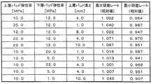
第四の知見として、プロファイル・コントロール型トップリングを具備した大径研磨部材回転型の研磨装置において、ウェーハの△ROQに応じて最大研磨レートと最小研磨レートが適切に設定された範囲内に入るように、エッジエリアの押付け圧力とリテーナリング圧力を共に調節することによっても、実用上十分な平坦度で研磨することができることに想到した。また、研磨部材の弾性率や厚さを変えて数値解析を行なったところ、研磨レートに対するリテーナリング圧力やエッジエリアの押付け圧力の影響力が、研磨部材の弾性率や厚さによって変わることを見出した。このことから鋭意研究した結果、ウェーハのロールオフに応じてリテーナリング圧力やエッジエリアの押付け圧力を調整して実用上十分な平坦度で研磨するのに好適な研磨部材の弾性率や厚さの範囲があることを見出した。 As a fourth finding, in a large-diameter polishing member rotating type polishing apparatus equipped with a profile-control type top ring, the maximum polishing rate and the minimum polishing rate fall within the range set appropriately according to the ΔROQ of the wafer. Thus, it has been conceived that polishing can be achieved with practically sufficient flatness by adjusting both the pressing pressure and the retainer ring pressure in the edge area. In addition, when numerical analysis was performed by changing the elastic modulus and thickness of the polishing member, it was found that the influence of retainer ring pressure and edge area pressing pressure on the polishing rate changes depending on the elastic modulus and thickness of the polishing member. It was. As a result of earnest research from this, as a result of adjusting the retainer ring pressure and the pressing pressure of the edge area according to the roll-off of the wafer, the elastic modulus and thickness of the polishing member suitable for polishing with sufficient flatness for practical use Found that there is a range.
上記の知見に鑑み且つ前記目的を実現するために、
請求項1に記載の発明は、
研磨部材と保持部材とを有する研磨部を備え、前記研磨部材と前記保持部材に保持された研磨対象物との間に圧力を加えつつ、前記研磨部材と前記研磨対象物とを相対運動させて前記研磨対象物を研磨する研磨装置であって、
前記研磨対象物の研磨中に前記研磨部材が該研磨対象物からはみ出したときに、前記研磨部材のはみ出した部分の少なくとも一部を支持するための支持面を有する支持部材と、
前記支持部材の前記支持面における支持圧力を調整するための圧力調整機構と、
前記研磨対象物のロールオフ量自体、ロールオフ量及び/又はロールオフ量を加工して得た情報により、前記支持圧力が所望の圧力となるように前記圧力調整機構を制御する制御部と、
を具備することを特徴とする研磨装置、
を提供する。In view of the above knowledge and in order to realize the above-mentioned object,
The invention described in
A polishing section having a polishing member and a holding member, and applying relative pressure between the polishing member and the polishing object held by the holding member while moving the polishing member and the polishing object relative to each other; A polishing apparatus for polishing the object to be polished,
A support member having a support surface for supporting at least a part of the protruding part of the polishing member when the polishing member protrudes from the polishing object during polishing of the polishing object;
A pressure adjustment mechanism for adjusting a support pressure on the support surface of the support member;
A control unit that controls the pressure adjustment mechanism so that the support pressure becomes a desired pressure according to information obtained by processing the roll-off amount itself, the roll-off amount and / or the roll-off amount of the polishing object;
A polishing apparatus comprising:
I will provide a.
なお、前記のロールオフ量に基づいた情報には、ロールオフ量自体、研磨装置の各部材の位置情報、ロールオフ量及び/又はロールオフ量を加工して得た情報、それらを使用して算出又は選択された支持圧力(リテーナリング圧力)を含むものとする。 The information based on the roll-off amount includes the roll-off amount itself, the position information of each member of the polishing apparatus, the information obtained by processing the roll-off amount and / or the roll-off amount, and the like. It includes the calculated or selected support pressure (retaining ring pressure).
請求項2の発明は、前記ロールオフ量自体、ロールオフ量及び/又はロールオフ量を加工して得た情報を取得するための測定部を備えることを特徴とする。 The invention of
請求項3の発明は、前記支持面の全面が同一の高さを有することを特徴とする。なお、前記支持面は厳密に同一の高さであることが好ましい。しかし、現実の研磨装置では例えば支持面を加工する際の面粗さや圧力調整機構などの遊びなどがあり、厳密に同一の高さにすることは困難であるが、実質的に同一と見なせる程度に高さが揃っていれば良い。 The invention according to
請求項4の発明は、前記支持部材が、前記研磨対象物の周囲に沿って配置された複数の支持要素からなり、それぞれの前記支持要素を、該支持要素の支持面が前記研磨対象物の研磨対象面と平行な平面にあって前記研磨対象物の周囲に沿う第一の位置と、前記研磨対象物の中心から前記第一の位置よりも放射状に離れた第二の位置との間に移動させることができることを特徴とする。 According to a fourth aspect of the present invention, the support member includes a plurality of support elements disposed along the periphery of the polishing object, and each of the support elements has a support surface of the polishing object. Between a first position along the periphery of the polishing object and a second position that is radially away from the center of the polishing object and radially away from the first position, in a plane parallel to the surface to be polished It can be moved.
請求項5の発明は、前記第一の位置が、前記研磨対象物の周縁と前記支持要素の支持面との間に実質的な隙間がない位置であることを特徴とする。 The invention of
請求項6の発明は、前記研磨部を複数備え、前記制御部が、それぞれの前記研磨部における前記支持圧力が独立して所望の圧力となるように、それぞれの前記研磨部に設けられた前記圧力調整機構を独立して作動させることを特徴とする。 The invention of
請求項7の発明は、
研磨部材と保持部材とを有する研磨部を備え、前記研磨部材と前記保持部材に保持された研磨対象物との間に圧力を加えつつ、前記研磨部材と前記研磨対象物とを相対運動させて前記研磨対象物を研磨する研磨装置であって、
前記研磨対象物の研磨中に前記研磨部材が該研磨対象物からはみ出したときに、前記研磨部材のはみ出した部分の少なくとも一部を支持するための支持面を有する支持部材と、
前記支持部材の前記支持面の高さを調整するための高さ調整機構と、
前記研磨対象物のロールオフ量自体、ロールオフ量及び/又はロールオフ量を加工して得た情報により、前記支持面の高さが所望の高さとなるように前記高さ調整機構を制御する制御部と、
を具備することを特徴とする研磨装置、
を提供する。The invention of claim 7
A polishing section having a polishing member and a holding member, and applying relative pressure between the polishing member and the polishing object held by the holding member while moving the polishing member and the polishing object relative to each other; A polishing apparatus for polishing the object to be polished,
A support member having a support surface for supporting at least a part of the protruding part of the polishing member when the polishing member protrudes from the polishing object during polishing of the polishing object;
A height adjustment mechanism for adjusting the height of the support surface of the support member;
The height adjustment mechanism is controlled so that the height of the support surface becomes a desired height based on information obtained by processing the roll-off amount itself, the roll-off amount and / or the roll-off amount of the polishing object. A control unit;
A polishing apparatus comprising:
I will provide a.
なお、前記のロールオフ量に基づいた情報には、ロールオフ量自体、研磨装置の各部材の位置情報、ロールオフ量及び/又はロールオフ量を加工して得た情報、それらを使用して算出又は選択された支持面の高さを含むものとする。 The information based on the roll-off amount includes the roll-off amount itself, position information of each member of the polishing apparatus, information obtained by processing the roll-off amount and / or the roll-off amount, and the like. It shall include the height of the calculated or selected support surface.
請求項8の発明は、前記ロールオフ量自体、ロールオフ量及び/又はロールオフ量を加工して得た情報を取得するための測定部を備えることを特徴とする。 The invention of
請求項9の発明は、前記支持面の全面が同一の高さを有することを特徴とする。なお、前記支持面は厳密に同一の高さであることが好ましい。しかし現実の研磨装置では例えば支持面を加工する際の面粗さや圧力調整機構などの遊びなどがあり、厳密に同一の高さにすることは困難であるが、実質的に同一と見なせる程度に高さが揃っていれば良い。 The invention according to
請求項10の発明は、前記支持部材が、前記研磨対象物の周囲に沿って配置された複数の支持要素からなり、それぞれの前記支持要素を、該支持要素の支持面が前記研磨対象物の研磨対象面と平行な平面にあって前記研磨対象物の周囲に沿う第一の位置と、前記研磨対象物の中心から前記第一の位置よりも放射状に離れた第二の位置との間に移動させることができることを特徴とする。 In the invention of
請求項11の発明は、前記第一の位置が、前記研磨対象物の周縁と前記支持要素の支持面との間に実質的な隙間がない位置であることを特徴とする。 The invention of
請求項12の発明は、前記研磨部を複数備え、前記制御部が、それぞれの前記研磨部における前記支持面の高さが独立して所望の高さとなるように、それぞれの前記研磨部に設けられた前記高さ調整機構を独立して作動させることを特徴とする。 The invention of
請求項13の発明は、
研磨部材と保持部材に保持された研磨対象物との間に圧力を加えつつ前記研磨部材と前記研磨対象物とを相対運動させて前記研磨対象物を研磨する期間に、前記研磨部材が該研磨対象物からはみ出したとき、前記研磨部材のはみ出した部分の少なくとも一部を支持する研磨方法であって、
前記研磨対象物のロールオフ量自体、ロールオフ量及び/又はロールオフ量を加工して得た情報を取得するステップと、
前記情報を含む情報に基づいて、前記はみ出した部分を支持するための支持圧力の所望の値を求めるステップと、
求められた前記所望の値に基づいて、前記支持圧力を調整するステップと、
を含むことを特徴とする研磨方法、
を提供する。The invention of claim 13
During the period in which the polishing member and the polishing object are moved relative to each other while the pressure is applied between the polishing member and the polishing object held by the holding member, the polishing member polishes the polishing object. A polishing method for supporting at least a part of a protruding portion of the polishing member when protruding from an object,
Obtaining information obtained by processing the roll-off amount itself, roll-off amount and / or roll-off amount of the polishing object;
Obtaining a desired value of a support pressure for supporting the protruding portion based on information including the information; and
Adjusting the support pressure based on the determined desired value;
A polishing method comprising:
I will provide a.
請求項14の発明は、
研磨部材と保持部材に保持された研磨対象物との間に圧力を加えつつ前記研磨部材と前記研磨対象物とを相対運動させて前記研磨対象物を研磨する期間に、前記研磨部材が該研磨対象物からはみ出したとき、前記研磨部材のはみ出した部分の少なくとも一部を支持する研磨方法をコンピュータに実施させるためのプログラムであっって、
前記研磨対象物のロールオフ量自体、ロールオフ量及び/又はロールオフ量を加工して得た情報を取得する指令と、
前記情報を含む情報に基づいて、前記はみ出した部分を支持するための支持圧力の所望の値を求める指令と、
求められた前記所望の値に基づいて、前記支持圧力を調整する指令と、
を含むことを特徴とするプログラム、
を提供する。The invention of claim 14
During the period in which the polishing member and the polishing object are moved relative to each other while the pressure is applied between the polishing member and the polishing object held by the holding member, the polishing member polishes the polishing object. A program for causing a computer to perform a polishing method for supporting at least a part of the protruding portion of the polishing member when protruding from an object,
A command to acquire information obtained by processing the roll-off amount itself, roll-off amount and / or roll-off amount of the polishing object;
Based on information including the information, a command for obtaining a desired value of a support pressure for supporting the protruding portion;
A command to adjust the support pressure based on the determined desired value;
A program characterized by including,
I will provide a.
請求項15の発明は、請求項14に係る発明のプログラムを記憶していることを特徴とするコンピュータ読み取り可能な記憶媒体に関する。 A fifteenth aspect of the present invention relates to a computer-readable storage medium that stores the program according to the fourteenth aspect of the present invention.
請求項16の発明は、請求項15に係る発明の記憶媒体に記憶されたプログラムの読み取り装置を備え、該記憶媒体から読み出されたプログラムにしたがって前記制御部が前記圧力調整機構を作動させることを特徴とする研磨装置に関する。 According to a sixteenth aspect of the present invention, there is provided a reading device for a program stored in the storage medium according to the fifteenth aspect, and the control unit operates the pressure adjusting mechanism according to the program read from the storage medium. The present invention relates to a polishing apparatus.
請求項17の発明は、
研磨部材と保持部材に保持された研磨対象物との間に圧力を加えつつ前記研磨部材と前記研磨対象物とを相対運動させて前記研磨対象物を研磨する期間に、前記研磨部材が該研磨対象物からはみ出したとき、前記研磨部材のはみ出した部分の少なくとも一部を支持する研磨方法であって、
前記研磨対象物のロールオフ量自体、ロールオフ量及び/又はロールオフ量を加工して得た情報を取得するステップと、
前記情報を含む情報に基づいて、前記はみ出した部分を支持するための支持面の高さの所望の値を求めるステップと、
求められた前記所望の値に基づいて、前記支持面の高さを調整するステップと、
を含むことを特徴とする研磨方法、
を提供する。The invention of
During the period in which the polishing member and the polishing object are moved relative to each other while the pressure is applied between the polishing member and the polishing object held by the holding member, the polishing member polishes the polishing object. A polishing method for supporting at least a part of a protruding portion of the polishing member when protruding from an object,
Obtaining information obtained by processing the roll-off amount itself, roll-off amount and / or roll-off amount of the polishing object;
Obtaining a desired value of the height of the support surface for supporting the protruding portion based on the information including the information; and
Adjusting the height of the support surface based on the desired value determined;
A polishing method comprising:
I will provide a.
請求項18の発明は、
研磨部材と保持部材に保持された研磨対象物との間に圧力を加えつつ、前記研磨部材と前記研磨対象物とを相対運動させて前記研磨対象物を研磨する期間に前記研磨部材が該研磨対象物からはみ出したとき前記研磨部材のはみ出した部分の少なくとも一部を支持する研磨方法をコンピュータに実施させるためのプログラムであって、
前記研磨対象物のロールオフ量自体、ロールオフ量及び/又はロールオフ量を加工して得た情報を取得する指令と、
前記情報を含む情報に基づいて、前記はみ出した部分を支持するための支持面の高さの所望の値を求める指令と、
求められた前記所望の値に基づいて、前記支持面の高さを調整する指令と、
を含むことを特徴とするプログラム、
を提供する。The invention of claim 18 provides
While the pressure is applied between the polishing member and the polishing object held by the holding member, the polishing member is polished during the period of polishing the polishing object by relatively moving the polishing member and the polishing object. A program for causing a computer to perform a polishing method for supporting at least a part of a protruding portion of the polishing member when protruding from an object,
A command to acquire information obtained by processing the roll-off amount itself, roll-off amount and / or roll-off amount of the polishing object;
Based on the information including the information, a command for obtaining a desired value of the height of the support surface for supporting the protruding portion;
Based on the determined desired value, a command to adjust the height of the support surface;
A program characterized by including,
I will provide a.
請求項19の発明は、請求項18に係る発明のプログラムを記憶していることを特徴とするコンピュータ読み取り可能な記憶媒体に関する。 The invention of claim 19 relates to a computer-readable storage medium characterized by storing the program of the invention of claim 18.
請求項20の発明は、請求項19に係る発明の記憶媒体に記憶されたプログラムの読み取り装置を備え、該記憶媒体から読み出されたプログラムにしたがって前記制御部が前記高さ調整機構を作動させることを特徴とする研磨装置に関する。 A twentieth aspect of the invention includes a reading device for a program stored in the storage medium according to the nineteenth aspect of the invention, and the control unit operates the height adjusting mechanism in accordance with the program read from the storage medium. The present invention relates to a polishing apparatus.
請求項21の発明は、
少なくとも2つの押圧部分を有し、該押圧部分ごとに任意の圧力を研磨対象物に加えることができる保持部材と、研磨部材とを有する研磨部を備え、前記研磨部材と前記保持部材に保持された研磨対象物との間に圧力を加えつつ、前記研磨部材と前記研磨対象物とを相対運動させて前記研磨対象物を研磨する研磨装置であって、
前記保持部材の前記押圧部分のうち、前記研磨対象物の最外部に対する押圧部分における押付け圧力を調整するための圧力調整機構と、
前記研磨対象物のロールオフ量自体、ロールオフ量及び/又はロールオフ量を加工して得た情報により、前記押付け圧力が所望の圧力となるように前記圧力調整機構を制御する制御部と、
を具備することを特徴とする研磨装置、
を提供する。The invention of
A polishing portion having at least two pressing portions, a holding member capable of applying an arbitrary pressure to the object to be polished for each pressing portion, and a polishing member, and held by the polishing member and the holding member A polishing apparatus for polishing the polishing object by relatively moving the polishing member and the polishing object while applying pressure between the polishing object and the polishing object,
A pressure adjusting mechanism for adjusting a pressing pressure in the pressing portion of the holding member with respect to the outermost portion of the polishing object;
A control unit that controls the pressure adjustment mechanism so that the pressing pressure becomes a desired pressure according to information obtained by processing the roll-off amount itself, the roll-off amount and / or the roll-off amount of the polishing object;
A polishing apparatus comprising:
I will provide a.
請求項22の発明は、前記ロールオフ量自体、ロールオフ量及び/又はロールオフ量を加工して得た情報を取得するための測定部を備えることを特徴とする。 According to a twenty-second aspect of the present invention, there is provided a measurement unit for acquiring information obtained by processing the roll-off amount itself, the roll-off amount and / or the roll-off amount.
請求項23の発明は、
少なくとも2つの押圧部分を有し、該押圧部分ごとに任意の圧力を研磨対象物に加えることができる保持部材に保持された研磨対象物と、研磨部材との間に圧力を加えつつ、前記研磨部材と前記研磨対象物とを相対運動させて前記研磨対象物を研磨する研磨方法であって、
前記研磨対象物のロールオフ量自体、ロールオフ量及び/又はロールオフ量を加工して得た情報を取得するステップと、
前記情報を含む情報に基づいて、前記保持部材の前記押圧部分のうち、前記研磨対象物の最外部に対する押圧部分における押付け圧力の所望の値を求めるステップと、
求められた前記所望の値に基づいて、前記押付け圧力を調整するステップと、
を含むことを特徴とする研磨方法、
を提供する。The invention of
The polishing is performed while applying pressure between the polishing object and the polishing object held by a holding member that has at least two pressing parts and can apply an arbitrary pressure to the polishing object for each pressing part. A polishing method for polishing the polishing object by relatively moving a member and the polishing object,
Obtaining information obtained by processing the roll-off amount itself, roll-off amount and / or roll-off amount of the polishing object;
Based on the information including the information, obtaining a desired value of the pressing pressure in the pressing portion with respect to the outermost portion of the polishing object among the pressing portions of the holding member;
Adjusting the pressing pressure based on the determined desired value;
A polishing method comprising:
I will provide a.
請求項24の発明は、
少なくとも2つの押圧部分を有し、該押圧部分ごとに任意の圧力を研磨対象物に加えることができる保持部材に保持された研磨対象物と、研磨部材との間に圧力を加えつつ、前記研磨部材と前記研磨対象物とを相対運動させて前記研磨対象物を研磨する研磨方法をコンピュータに実施させるためのプログラムであって、
前記研磨対象物のロールオフ量自体、ロールオフ量及び/又はロールオフ量を加工して得た情報を取得する指令と、
前記情報を含む情報に基づいて、前記保持部材の前記押圧部分のうち、前記研磨対象物の最外部に対する押圧部分における押付け圧力の所望の値を求める指令と、
求められた前記所望の値に基づいて、前記押付け圧力を調整する指令と、
を含むことを特徴とするプログラム、
を提供する。The invention of
The polishing is performed while applying pressure between the polishing object and the polishing object held by a holding member that has at least two pressing parts and can apply an arbitrary pressure to the polishing object for each pressing part. A program for causing a computer to perform a polishing method for polishing a polishing object by relatively moving a member and the polishing object,
A command to acquire information obtained by processing the roll-off amount itself, roll-off amount and / or roll-off amount of the polishing object;
Based on the information including the information, a command for obtaining a desired value of the pressing pressure in the pressing portion with respect to the outermost part of the polishing object among the pressing portions of the holding member;
A command to adjust the pressing pressure based on the determined desired value;
A program characterized by including,
I will provide a.
請求項25の発明は、請求項24に係る発明のプログラムを記憶していることを特徴とするコンピュータ読み取り可能な記憶媒体を提供する。 The invention of
請求項26の発明は、請求項25に係る発明の記憶媒体に記憶されたプログラムの読み取り装置を備え、該記憶媒体から読み出されたプログラムにしたがって前記制御部が前記圧力調整機構を作動させることを特徴とする研磨装置を提供する。 A twenty-sixth aspect of the invention includes a reading device for a program stored in the storage medium according to the twenty-fifth aspect of the invention, and the control unit operates the pressure adjusting mechanism in accordance with the program read from the storage medium. A polishing apparatus is provided.
請求項27の発明は、
研磨部材と、支持部材と、少なくとも2つの押圧部分とを備える保持部材とを有する研磨部を備え、前記研磨部材と前記保持部材に保持された研磨対象物との間に圧力を加えつつ、前記研磨部材と前記研磨対象物とを相対運動させて前記研磨対象物を研磨する研磨装置であって、前記支持部材が、前記研磨対象物の研磨中に前記研磨部材が前記研磨対象物からはみ出したときに、前記研磨部材のはみ出した部分の少なくとも一部を支持するための支持面を有する研磨装置において、
前記保持部材の前記押圧部分のうち、前記研磨対象物の最外部に対する押圧部分における押付け圧力を調整するための圧力調整機構と、
前記支持部材の前記支持面における支持圧力を調整するための圧力調整機構と、
前記研磨対象物のロールオフ量自体、ロールオフ量及び/又はロールオフ量を加工して得た情報により、前記押付け圧力および前記支持圧力が所望の圧力となるように前記圧力調整機構を制御する制御部と、
を具備することを特徴とする研磨装置、
を提供する。The invention of claim 27 provides
A polishing portion having a polishing member, a support member, and a holding member including at least two pressing portions, and while applying pressure between the polishing member and an object to be polished held by the holding member, A polishing apparatus for polishing a polishing object by relatively moving a polishing member and the polishing object, wherein the support member protrudes from the polishing object during polishing of the polishing object. Sometimes, in the polishing apparatus having a support surface for supporting at least a part of the protruding portion of the polishing member,
A pressure adjusting mechanism for adjusting a pressing pressure in the pressing portion of the holding member with respect to the outermost portion of the polishing object;
A pressure adjustment mechanism for adjusting a support pressure on the support surface of the support member;
The pressure adjustment mechanism is controlled so that the pressing pressure and the support pressure become desired pressures based on information obtained by processing the roll-off amount itself, the roll-off amount and / or the roll-off amount of the polishing object. A control unit;
A polishing apparatus comprising:
I will provide a.
請求項28の発明は、前記ロールオフ量自体、ロールオフ量及び/又はロールオフ量を加工して得た情報を取得するための測定部を備えることを特徴とする。 A twenty-eighth aspect of the invention is characterized by comprising a measurement unit for acquiring information obtained by processing the roll-off amount itself, the roll-off amount and / or the roll-off amount.
請求項29の発明は、
研磨部材と、支持部材と、少なくとも2つの押圧部分とを備える保持部材とを有する研磨部を備え、前記研磨部材と前記保持部材に保持された研磨対象物との間に圧力を加えつつ、前記研磨部材と前記研磨対象物とを相対運動させて前記研磨対象物を研磨する研磨方法であって、前記支持部材が、前記研磨対象物の研磨中に前記研磨部材が前記研磨対象物からはみ出したときに、前記研磨部材のはみ出した部分の少なくとも一部を支持するための支持面を有する研磨装置において、
前記研磨対象物のロールオフ量自体、ロールオフ量及び/又はロールオフ量を加工して得た情報を取得するステップと、
前記情報を含む情報に基づいて、前記支持部材の前記支持面における支持圧力の所望の値を求めるステップと、
前記情報を含む情報に基づいて、前記保持部材の前記押圧部分のうち、前記研磨対象物の最外部に対する押圧部分における押付け圧力の所望の値を求めるステップと、
求められた前記所望の値に基づいて、前記支持圧力および前記押付け圧力を調整するステップと、
を含むことを特徴とする研磨方法、
を提供する。The invention of
A polishing portion having a polishing member, a support member, and a holding member including at least two pressing portions, and while applying pressure between the polishing member and an object to be polished held by the holding member, A polishing method for polishing a polishing object by relatively moving a polishing member and the polishing object, wherein the support member protrudes from the polishing object during polishing of the polishing object. Sometimes, in the polishing apparatus having a support surface for supporting at least a part of the protruding portion of the polishing member,
Obtaining information obtained by processing the roll-off amount itself, roll-off amount and / or roll-off amount of the polishing object;
Obtaining a desired value of the support pressure at the support surface of the support member based on the information including the information; and
Based on the information including the information, obtaining a desired value of the pressing pressure in the pressing portion with respect to the outermost portion of the polishing object among the pressing portions of the holding member;
Adjusting the support pressure and the pressing pressure based on the determined desired value;
A polishing method comprising:
I will provide a.
請求項30の発明は、
研磨部材と、支持部材と、少なくとも2つの押圧部分とを備える保持部材とを有する研磨部を備え、前記研磨部材と前記保持部材に保持された研磨対象物との間に圧力を加えつつ、前記研磨部材と前記研磨対象物とを相対運動させて前記研磨対象物を研磨する研磨方法であって、前記支持部材が、前記研磨対象物の研磨中に前記研磨部材が前記研磨対象物からはみ出したときに、前記研磨部材のはみ出した部分の少なくとも一部を支持するための支持面を有する研磨方法をコンピュータに実施させるためのプログラムにおいて、
前記研磨対象物のロールオフ量自体、ロールオフ量及び/又はロールオフ量を加工して得た情報を取得する指令と、
前記情報を含む情報に基づいて、前記支持部材の前記支持面における支持圧力の所望の値を求める指令と、
前記情報を含む情報に基づいて、前記保持部材の前記押圧部分のうち、前記研磨対象物の最外部に対する押圧部分における押付け圧力の所望の値を求める指令と、
求められた前記所望の値に基づいて、前記支持圧力および前記押付け圧力を調整する指令と、
を含むことを特徴とするプログラム、
を提供する。The invention of
A polishing portion having a polishing member, a support member, and a holding member including at least two pressing portions, and while applying pressure between the polishing member and an object to be polished held by the holding member, A polishing method for polishing a polishing object by relatively moving a polishing member and the polishing object, wherein the support member protrudes from the polishing object during polishing of the polishing object. Sometimes, in a program for causing a computer to perform a polishing method having a support surface for supporting at least a part of the protruding portion of the polishing member,
A command to acquire information obtained by processing the roll-off amount itself, roll-off amount and / or roll-off amount of the polishing object;
Based on information including the information, a command for obtaining a desired value of the support pressure on the support surface of the support member;
Based on the information including the information, a command for obtaining a desired value of the pressing pressure in the pressing portion with respect to the outermost part of the polishing object among the pressing portions of the holding member;
A command for adjusting the support pressure and the pressing pressure based on the desired value obtained;
A program characterized by including,
I will provide a.
請求項31の発明は、請求項30に記載のプログラムを記憶していることを特徴とするコンピュータ読み取り可能な記憶媒体を提供する。 A thirty-first aspect of the invention provides a computer-readable storage medium storing the program according to the thirty-third aspect.
請求項32の発明は、請求項31に係る発明の記憶媒体に記録されたプログラムの読み取り装置を備え、該記憶媒体から読み出されたプログラムにしたがって前記制御部が前記圧力調整機構を作動させることを特徴とする研磨装置を提供する。 According to a thirty-second aspect of the present invention, there is provided a reading device for a program recorded in the storage medium according to the thirty-first aspect, and the control unit operates the pressure adjusting mechanism according to the program read from the storage medium. A polishing apparatus is provided.
請求項33の発明は、請求項1〜12、16、20、21、22、26、27、28及び32のうちのいずれか一つに記載の研磨装置を用いて、ウェーハの表面を平坦化する工程を備えることを特徴とする半導体デバイス製造方法を提供する。 The invention of claim 33 flattens the surface of the wafer using the polishing apparatus according to any one of
請求項34の発明は、請求項13、17、23及び29のうちのいずれか一つに記載の研磨方法を用いて、ウェーハの表面を平坦化する工程を備えることを特徴とする半導体デバイス製造方法を提供する。 A thirty-fourth aspect of the invention is a semiconductor device manufacturing comprising the step of planarizing the surface of a wafer using the polishing method according to any one of the thirteenth, seventeenth, twenty-third, and twenty-ninth aspects. Provide a method.
請求項35の発明は、請求項33又は34に記載の半導体デバイス製造方法により製造されることを特徴とする半導体デバイスを提供する。 A thirty-fifth aspect of the invention provides a semiconductor device manufactured by the semiconductor device manufacturing method according to the thirty-third or thirty-fourth aspect.
請求項1〜35の発明のそれぞれにおいて、研磨部材の大きさは研磨対象物の大きさと同一であっても、研磨部材の方が研磨対象物より大きくても、研磨部材の方が研磨対象物より小さくてもよい。また、支持部は保持部に対して固定されていても、固定されていなくてもよい。更に、ロールオフ量に基づいた情報には、ロールオフ量(例えば、ROQ(r、θ))、ロールオフ量を測定して得た電気信号や数値、それらを加工して得た情報、及び、それらを使用して算出又は選択された支持面の高さ/支持圧力を含むものとする。なお、支持面の高さ/支持圧力を算出するに当たっては、ロールオフ量の他に、研磨装置やロールオフ測定装置の各種部材の位置情報を使用して算出してもよい。
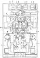
以下、本発明に係る研磨装置の若干の実施の形態について添付図面を参照しながら説明する。図1は、本発明に係る研磨装置の第一の実施の形態である、ウェーハを研磨するための化学機械研磨装置の各部の配置構成を示す平面図である。図1に示す化学機械研磨装置は多数のウェーハをストックするウェーハ・カセット21を載置するための4つのロード・アンロード・ステージ22を備えている。ロード・アンロード・ステージ22は昇降可能な機構を有していてもよい。ロード・アンロード・ステージ22上の各ウェーハ・カセット21に到達可能となるように、走行機構23の上に2つのハンドを有する搬送ロボット24が配置される。 Hereinafter, some embodiments of a polishing apparatus according to the present invention will be described with reference to the accompanying drawings. FIG. 1 is a plan view showing the arrangement of each part of a chemical mechanical polishing apparatus for polishing a wafer, which is a first embodiment of a polishing apparatus according to the present invention. The chemical mechanical polishing apparatus shown in FIG. 1 includes four load / unload
搬送ロボット24における2つのハンドのうち、下側のハンドはウェーハ・カセット21よりウェーハを受け取るときのみに使用され、上側のハンドはウェーハ・カセット21にウェーハを戻すときのみに使用される。これは、洗浄後のクリーンなウェーハを上側にストックし、それ以上ウェーハを汚さないための配置である。下側のハンドはウェーハを真空吸着する吸着型ハンドであり、上側のハンドはウェーハの周縁部を保持する落し込み型ハンドであることが好ましい。吸着型ハンドはカセット内のウェーハのずれに関係なく正確に搬送することができ、落し込み型ハンドは真空吸着のように塵埃を集めてこないのでウェーハ裏面のクリーン度を保って搬送することができる。 Of the two hands in the
搬送ロボット24の走行機構23を対称軸にしてウェーハ・カセット21とは反対側に、2台の洗浄機25、26が配置される。各洗浄機25、26は搬送ロボット24のハンドが到達可能な位置に配置されており、2台の洗浄機25、26の間で搬送ロボット24が到達可能な位置に、4つのウェーハ載置台27、28、29、30を備えたウェーハ・ステーション70が配置されている。洗浄機25、26はウェーハを高速回転させて乾燥させるスピン・ドライ機能を有しており、これにより、モジュール交換することなくウェーハの2段洗浄及び3段洗浄に対応することができる。 Two
洗浄機25、26及び載置台27、28、29、30が配置されている領域Bとウエハ・カセット21及び搬送ロボット24が配置されている領域Aとのクリーン度を分けるために隔壁84が設置される。隔壁84には、両領域A、B間でウェーハを搬送するための開口部にシャッター31が設けられている。洗浄機25と3つの載置台27、29、30とに到達可能な位置に、2つのハンドを有する搬送ロボット80が配置されており、洗浄機26と3つの載置台28、29、30とに到達可能な位置に、2つのハンドを有する搬送ロボット81が配置されている。 A
載置台27は、搬送ロボット24と搬送ロボット80との間でウェーハを相互に受け渡すために使用され、ウェーハの有無を検知するためのセンサ91を備えている。載置台28は、搬送ロボット24と搬送ロボット81との間でウェーハを受け渡すために使用され、ウェーハの有無を検知するためのセンサ92を備える。載置台29は、搬送ロボット81から搬送ロボット80へウェーハを搬送するために使用され、ウェーハの有無を検知するためのセンサ93とウェーハの乾燥防止用又は洗浄用のリンス・ノズル95を備えている。載置台30は、搬送ロボット80から搬送ロボット81へウェーハを搬送するために使用され、ウェーハの有無を検知するためのセンサ94とウェーハの乾燥防止用又は洗浄用のリンス・ノズル96を備えている。載置台29、30は共通の防水カバーの中に配置され、この防水カバーの搬送のための開口部にはシャッター97が設けられている。載置台29は載置台30の上にあり、洗浄後のウェーハは載置台29に、洗浄前のウェーハは載置台30に置かれる。これにより、リンス水の落下による汚染が防止される。なお、図1においては、センサ91、92、93、94、リンス・ノズル95、96及びシャッター97は模式的に示したものであって、位置及び形状は正確に図示されていない。 The mounting table 27 is used to transfer wafers between the
搬送ロボット80、81の上側のハンドは、一度洗浄されたウェーハを洗浄機又はウェーハ・ステーション70の載置台へ搬送するのに使用され、下側のハンドは1度も洗浄されていないウェーハと研磨される前のウェーハとを搬送するのに使用される。下側のハンドで反転機(これについては後述する)へのウェーハの出し入れを行うことにより、反転機の上部の壁からリンス水のしずくが垂れて上側のハンドを汚染することがない。 The upper hand of the
洗浄機25と隣接するように且つ搬送ロボット80のハンドが到達可能な位置に、洗浄機82が配置されている。また、洗浄機26と隣接するように且つ搬送ロボット81のハンドが到達可能な位置に、洗浄機83が配置されている。これらの洗浄機25、26、82、83、ウェーハ・ステーション70の載置台27、28、29、30及び搬送ロボット80、81は全て、領域A内の気圧よりも低い気圧に調整されている領域Bに配置される。洗浄機82、83は両面洗浄可能な洗浄機である。 A cleaning
図1に示す化学機械研磨装置を構成する各機器はハウジング66によって囲まれ、ハウジング66内は隔壁84、85、86、87、67によって(領域A、Bを含む)複数の部屋に区画される。隔壁87によって、領域Bと区分されたポリッシング室が形成される。このポリッシング室は、隔壁67によって、第一の研磨部である領域Cと第二の研磨部である領域Dとに区分される。それぞれの領域C、Dには、2つの研磨テーブルと、1枚のウェーハを保持し且つウェーハを研磨テーブルに対して押し付けながら研磨するための1つのトップリングとが配置される。即ち、領域Cには研磨テーブル54、56が配置され、領域Dには研磨テーブル55、57が配置されており、また、領域Cにはトップリング52が配置され、領域Dにはトップリング53が配置されている。更に、領域Cには、研磨テーブル54に研磨砥液を供給するための砥液ノズル60と、研磨テーブル54のドレッシングを行うためのドレッサ58とが配置され、領域Dには、研磨テーブル55に研磨砥液を供給するための砥液ノズル61と、研磨テーブル55のドレッシングを行うためのドレッサ59とが配置されている。加えて、領域Cには研磨テーブル56のドレッシングを行うためのドレッサ68が、領域Dには研磨テーブル57のドレッシングを行うためのドレッサ69が配置されている。なお、研磨テーブル56、57の代わりに、湿式タイプのウェーハ膜厚測定機を設置してもよい。その場合には、研磨直後のウェーハの膜厚を測定することができるので、ウェーハの削り増しや、測定値を利用しての次のウェーハの研磨プロセスの制御を行うことができる。 1 are surrounded by a
ポリッシング室と領域Bとの間でウェーハの受け渡しを行うために、搬送ロボット80、81と、トップリング52、53が到達可能な位置に、ウェーハを表裏反転させるための反転機99、100、101、102を備えた回転式ウェーハ・ステーション98が配置されている。反転機99、100、101、102は回転式ウェーハ・ステーションの回転に伴って回転する。回転式ウェーハ・ステーション98に配置された反転機99〜102が領域B側、即ち、図1の配置では反転機99、100に相当する位置にあるときにウェーハの研磨対象面のロールオフ量に応じた情報を取得するために、測定部として、触針方式、光学方式、渦電流センサを含む電気方式、磁気方式、電磁方式、流体方式等の変位計103、104が回転式ウェーハ・ステーション98の上方に備えられている。 In order to transfer the wafer between the polishing chamber and the region B, reversing
ここで、ポリッシング室と領域Bとの間でウェーハを受け渡す方法を説明する。ここで、回転式ウェーハ・ステーション98に備えられている反転機について、図1に示すように、領域B側に反転機99、100が、領域C側に反転機101が、領域D側に反転機102が配置されていると仮定する。研磨に供されるウェーハは、搬送ロボット80によりウェーハ・ステーション70から回転式ウェーハ・ステーション98の領域B側に配置された反転機99に渡される。別のウェーハは、搬送ロボット81によりウェーハ・ステーション70から回転式ウェーハ・ステーション98の領域B側に配置された反転機100に渡される。なお、搬送ロボット80がウェーハを回転式ウェーハ・ステーション98に搬送する際、隔壁87に設けられたシャッター45が開くので、領域Bとポリッシング室との間でのウェーハの受け渡しが可能となる。また、搬送ロボット81がウェーハを回転式ウェーハ・ステーション98に搬送する際には、隔壁87に設けられたシャッター46が開き、領域Bとポリッシング室との間でのウェーハの受け渡しを可能とする。反転機99にウェーハを渡した後、変位計103によってウェーハの研磨対象面のロールオフ量が測定され、反転機100に別のウェーハを渡した後に変位計104によって研磨対象面のロールオフ量が測定される。 Here, a method for delivering a wafer between the polishing chamber and the region B will be described. Here, as shown in FIG. 1, the reversing machines provided in the
こうしてロールオフ量の測定が完了すると、回転式ウェーハ・ステーション98がその軸を中心に180度回転し、反転機99を領域D側に、反転機100を領域C側に移動させる。回転ウェーハ・ステーションにより領域C側へ移動させられたウェーハは、反転機100により、研磨対象面が上向きから下向きになるよう反転させられてからトップリング52へ移送される。また、回転ウェーハ・ステーションにより領域D側へ移動させられたウェーハは、反転機99により、研磨対象面が上向きから下向きになるよう反転させられてからトップリング53へ移送される。トップリング52、53へ移送されたウェーハは、トップリングの真空吸着機構により吸着されて研磨テーブル54又は研磨テーブル55まで吸着されたまま搬送された後、研磨テーブル54、55上に取り付けられた研磨パッドによって研磨される。 When the measurement of the roll-off amount is completed in this way, the
以下、本発明に係る研磨装置における研磨部とその制御系統との実施の形態について説明する。 Hereinafter, embodiments of a polishing unit and its control system in a polishing apparatus according to the present invention will be described.
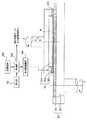
図2は、本発明に係る研磨装置における研磨部とその制御系統との第一の実施の形態を示す図で、研磨部はトップリングと研磨テーブルとを備え、図2は、トップリング52及び研磨テーブル54の一部の断面と制御系統の一例とを模式的に示している。トップリング53と研磨テーブル55も同様の構造を有する。図2に示すように、トップリング52はウェーハWが研磨パッド201のエッジからはみ出さないように位置決めされる。研磨対象物であるウェーハWを保持するトップリング52は、ウェーハWを研磨パッド201に所定の圧力で押付けるためのエアバッグ202と、ウェーハWを取り囲むように設置されたリテーナリング203と、リテーナリング203に所定の支持圧力でウェーハWの周囲の研磨パッド201を押付けさせるためのエアバッグ204とを備えている。以下の説明において、リテーナリング203の下面が研磨パッド201を押し付ける圧力を「支持圧力」と呼ぶことにする。 FIG. 2 is a diagram showing a first embodiment of a polishing unit and its control system in a polishing apparatus according to the present invention. The polishing unit includes a top ring and a polishing table. A partial cross section of the polishing table 54 and an example of a control system are schematically shown. The top ring 53 and the polishing table 55 have the same structure. As shown in FIG. 2, the
ここで説明している第一の実施の形態においては、エアバッグ202は、図2に示すように一つの区画であっても、同心円状に複数の区画に分かれていてもよい。また、リテーナリング203は、図2に示すように、トップリング52に保持されたウェーハWの外周との間に若干の隙間をあけ且つ該外周に沿う円環状をなすとともに断面長方形状の単一の部材205で構成されている。因みに、本実施の形態ではリテーナリング203は単一の部材から成る例を示したが、例えば、積層された部材等の複合的な部材から構成されていても良い。この部材205の下面は、ウェーハWの研磨対象面の周囲を囲む研磨パッド201の部分を押し付ける押圧面をなすよう、全体に渡ってほぼ同一の高さを持つ平面となっている。部材205は、例えば、ジルコニアやアルミナ等のセラミック材料や、エポキシ(EP)樹脂、フェノール(PF)樹脂、ポリフェニレンサルファイド(PPS)樹脂等のエンジニアリング・プラスチック材料で構成されることが望ましい。 In the first embodiment described here, the
リテーナリング203が研磨パッド201を押し付ける支持圧力は、圧力調整機構206によってエアバッグ204の圧力を制御することにより調整される。なお、エアバッグ204を設けずに軸からの荷重を圧力調整機構206により制御することによって上記支持圧力を調整するようにしてもよい。 The support pressure at which the
研磨テーブル54は研磨パッド201と研磨定盤207とを備えている。研磨パッド201は、図2のように一層の単層パッドであっても、二層以上の多層パッドであってもよい。研磨の際、トップリング52は、ウェーハWを研磨パッド201に押付けながら、その軸を中心に矢印Aの向きに回転する。同時に、研磨テーブル54もその軸を中心に矢印Bの方向に回転する。この場合、後述のように、リテーナリング203の支持圧力を、測定したロールオフ量により適切に設定すると、ロールオフのばらつきによる研磨プロファイルのばらつきを抑えることができ、実用上十分な平坦度でウェーハWを研磨することができる。 The polishing table 54 includes a
ここで図1に戻って、トップリング52、53がそれぞれに到達可能な位置に、前述した第2の研磨テーブル56、57が配置されている。これにより、ウェーハは第1の研磨テーブル54、55で研磨された後、第2の研磨テーブル56、57に貼着された仕上げ用研磨パッドで仕上げ研磨される。仕上げ用の第2の研磨テーブル56、57においては、SUBA400やPolytex(共にロデール・ニッタ製の研磨パッドの商品名である)等の研磨パッドに砥粒を含まない薬液又は純水を供給しながら純水仕上げを行い、又はスラリを供給して研磨を行う。 Here, referring back to FIG. 1, the above-described second polishing tables 56 and 57 are arranged at positions where the top rings 52 and 53 can reach each other. As a result, the wafer is polished by the first polishing tables 54, 55 and then polished by the finishing polishing pad attached to the second polishing tables 56, 57. In the second polishing tables 56 and 57 for finishing, a chemical solution or pure water not containing abrasive grains is supplied to a polishing pad such as SUBA400 or Polytex (both are trade names of polishing pads manufactured by Rodel Nitta). Polishing with pure water finish or supplying slurry.
なお、研磨期間に、搬送ロボット80、81により、次の研磨に供されるウェーハを領域B側に移動した反転機101、102に渡して変位計103、104によりロールオフ量を測定してもよい。こうすると、研磨とロールオフ量の測定とを同時に行うことができるので、研磨のスループットを向上させることができる。
研磨が終了したウェーハは、トップリング52、53により、それぞれ反転機99、100に移送される。反転機99、100に移送されたウェーハは、反転機99、100により研磨対象面が上向きなるように反転させられる。その後、回転式ウェーハ・ステーション98が180度回転してウェーハを領域B側へ移動させる。領域B側へ移動したウェーハは、搬送ロボット80により反転機99から洗浄機82又はウェーハ・ステーション70に搬送される。領域B側へ移動した別のウェーハは、搬送ロボット81により反転機100から洗浄機83又はウェーハ・ステーション70に搬送される。その後、適切な洗浄工程を経て、ウェーハ・カセット21へ収納される。Note that during the polishing period, the
The polished wafers are transferred to the reversing
本実施の形態においては、ウェーハの研磨対象面のロールオフ量に応じた情報を取得する測定部として、変位計103、104を回転式ウェーハ・ステーション98の上方に設ける構成としたが、測定部を研磨装置のどこに設置するかは任意である。また、測定部は研磨装置と一体となっていなくてもよく、ウェーハを研磨装置に投入する前に、研磨装置の外部に設けた測定器を用いてロールオフ量を予め測定しておき、その情報を図示しない入力装置で制御部124又は記憶媒体126に入力するようにしてもよい。測定器としては、例えば(株)コベルコ科研のエッジロールオフ測定装置(LER−100)がある。 In the present embodiment, the
次に、リテーナリング203の支持圧力を設定する方法の一例を説明する。なお、説明の便宜上、支持圧力は、ウェーハWの研磨対象面に研磨パッド201を押付ける圧力即ち研磨圧力に対する相対値として表すこととする。ウェーハWの研磨対象面のロールオフ量がウェーハ中心部ではROQ0、ウェーハ・エッジから1mmの地点でROQ1であるとする。ROQ1として、ウェーハWの周方向の各点を平均した値を用いても、1つの点のみの値を代表値として用いてもよい。 Next, an example of a method for setting the support pressure of the
まず、ウェーハ・エッジから1mmの地点でのロールオフ量とウェーハ中心部でのロールオフ量との差△ROQ=ROQ1−ROQ0を算出する。次に、研磨後にエッジ・イクスクルージョンの内側が平坦な領域となるように、予め求めておいた△ROQと支持圧力との関係に基づいて、算出した△ROQに対応する面圧を求める。最後に、制御部208によって、リテーナリング203の支持圧力を上記により求めた面圧に設定する。 First, the difference ΔROQ = ROQ1−ROQ0 between the roll-off amount at a
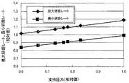
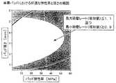
ここで、エッジ・イクスクルージョンの内側が平坦な領域となるように△ROQと支持圧力との関係を予め求める方法の一例を説明する。図3は、△ROQ=0.5μmのウェーハにおいて、エッジ・イクスクルージョンを2mmとしたときの最大研磨レート及び最小研磨レートの相対値と支持圧力との関係を示している。通常の研磨においては、幾何学的に完全に平坦な面は作成不可能であるが、例えばリソグラフィー・プロセスなどの半導体デバイス製造プロセスにおいては、実用上十分な平坦度まで研磨できれば十分である。そこで、以下の説明においては、このような実用上十分な平坦度に研磨された表面を「平坦な表面」であるとする。また、研磨レートのばらつきの許容値として適切な値を選ぶことにより、研磨後の研磨対象面を十分な平坦度とすることできるということが経験的に分かっている。したがって、最大研磨レート及び最小研磨レートが共に研磨レートのばらつきの許容値内に入っていれば、エッジ・イクスクルージョンの内側は研磨後には平坦な領域となると言える。したがって、図3の場合、研磨レートのばらつきの許容値を研磨レートの相対値で例えば1.0±0.1とすると、支持圧力を研磨圧力に対しておよそ0.75倍から0.80倍の間に設定すれば、エッジ・イクスクルージョンの内側は平坦な領域となることが分かる。 Here, an example of a method for obtaining in advance the relationship between ΔROQ and the support pressure so that the inside of the edge exclusion is a flat region will be described. FIG. 3 shows the relationship between the relative values of the maximum polishing rate and the minimum polishing rate and the support pressure when the edge exclusion is 2 mm in a wafer with ΔROQ = 0.5 μm. In normal polishing, it is impossible to create a geometrically completely flat surface. However, in a semiconductor device manufacturing process such as a lithography process, it is sufficient that polishing can be performed to a sufficiently flatness for practical use. Therefore, in the following description, it is assumed that the surface polished to such a practically sufficient flatness is a “flat surface”. Further, it has been empirically known that the surface to be polished after polishing can have a sufficient flatness by selecting an appropriate value as an allowable value of variation in polishing rate. Therefore, if the maximum polishing rate and the minimum polishing rate are both within the allowable value of variation in the polishing rate, it can be said that the inside of the edge exclusion is a flat region after polishing. Therefore, in the case of FIG. 3, when the allowable value of the variation in the polishing rate is, for example, 1.0 ± 0.1 in terms of the relative value of the polishing rate, the support pressure is approximately 0.75 to 0.80 times the polishing pressure. It can be seen that the inside of the edge exclusion is a flat region if set between.
△ROQが異なれば、最大研磨レート及び最小研磨レートの相対値と支持圧力との関係も異なってくる。したがって、各△ROQにおける支持圧力を上記のようにして求めておけば、エッジ・イクスクルージョンの内側が平坦な領域となるように△ROQと支持圧力との関係を予め求めることができる。しかし、全ての△ROQに対して支持圧力を求めることは困難なため、実際には、数点の△ROQに対して支持圧力を求め、それらの点間を補間式を用いて補間することになる。 If ΔROQ is different, the relationship between the relative values of the maximum polishing rate and the minimum polishing rate and the support pressure is also different. Therefore, if the support pressure at each ΔROQ is determined as described above, the relationship between ΔROQ and the support pressure can be determined in advance so that the inside of the edge exclusion is a flat region. However, since it is difficult to obtain support pressures for all ΔROQs, in practice, support pressures are obtained for several ΔROQs, and interpolation between these points is performed using an interpolation formula. Become.
上述の支持圧力の設定例では、ウェーハ・エッジから1mmの地点でのロールオフ量とウェーハ中心部でのロールオフ量との差△ROQを用いている。しかし、支持圧力の設定は前述の△ROQに限られるものではなく、ロールオフ量に基づいた情報であれば、非特許文献2に記載のROAであってもよいし、ロールオフ量を多項式等の近似式で近似したときの係数であってもよい。 In the above setting example of the support pressure, the difference ΔROQ between the roll-off amount at a
エッジ・イクスクルージョンの内側が平坦な領域となるように予め求めておいた△ROQと支持圧力との関係に関する情報は、記憶媒体209に記憶される。そこで、制御部208は、記憶媒体209に記憶されている、エッジ・イクスクルージョンの内側が平坦な領域となるように予め求めた△ROQと支持圧力との関係に関する情報と、それにアクセスするためのプログラムとにより、変位計103により取得されたウェーハWの研磨対象面のロールオフ量の測定結果に基づいて、支持圧力を制御する。記憶媒体209には、前述の情報やプログラムの他に、変位計103により取得されたウェーハWの研磨対象面のロールオフ量の測定結果に基づいて支持圧力を制御するためのプログラムを記憶させてもよい。また、トップリング52、53、研磨テーブル54、55、56、57を駆動するモータ、変位計103、104、搬送ロボット80、81等の、研磨装置を構成する他の部位を制御するためのプログラムも記憶媒体209に記憶しておくことができる。 Information regarding the relationship between ΔROQ and the support pressure, which is obtained in advance so that the inside of the edge exclusion is a flat region, is stored in the
以上説明したところから理解されるように、本発明の第一の実施の形態においては、研磨パッド201のリバウンドによるウェーハWへの影響を、ウェーハWのロールオフ量のばらつきに応じて最適化することによって低減することができる。 As can be understood from the above description, in the first embodiment of the present invention, the influence on the wafer W due to the rebound of the
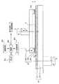
図4は、本発明に係る研磨装置の第二の実施の形態における研磨部の断面とその制御系統とを模式的に示す図である。図2に示す第一の実施の形態と同様に、研磨部はトップリングと研磨テーブルとを備え、図4は、トップリング52′及び研磨テーブル54の一部の断面と制御系統の一例とを模式的に示している。図5は、図4における線DEに沿って矢印の方向を見たときの断面図である。図4及び図5において、図2における構成要素と同一又は対応する構成要素には同一符号を付すこととし、それらについての重複する説明は省略する。そこで、以下では、本発明の第二の実施の形態が第一の実施の形態と異なる点を中心にして説明する。 FIG. 4 is a diagram schematically showing a cross section of a polishing portion and its control system in the second embodiment of the polishing apparatus according to the present invention. As in the first embodiment shown in FIG. 2, the polishing section includes a top ring and a polishing table. FIG. 4 shows a partial cross section of the top ring 52 'and the polishing table 54 and an example of a control system. This is shown schematically. FIG. 5 is a cross-sectional view of the arrow direction along the line DE in FIG. 4 and 5, the same or corresponding components as those in FIG. 2 are denoted by the same reference numerals, and redundant description thereof is omitted. Therefore, in the following, the second embodiment of the present invention will be described focusing on differences from the first embodiment.
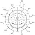
まず、第二の実施の形態では、図2における単一のリテーナリング203の代わりに、研磨パッド201を押付ける押圧面を有する複数の押圧部材からなるリテーナリング301が用いられる。具体的には、リテーナリング301はウェーハWの周囲に沿って順次配置され且つトップリング52′の中心軸を通る面に沿って所定の角度ずつ互いに分離された所定の個数の独立した押圧部材からなる。図5においては、リテーナリング301は、ウェーハWの周囲に沿って順次配置され且つトップリング52′の中心軸を通る面に沿って30゜ずつ互いに分離された12個の独立した押圧部材301a〜301lから構成される。押圧部材301aは、図4及び図5に示すように、ウェーハWの外周に内周面側が若干の隙間を空けて沿うように形成され、その長さ方向に円弧状をなし且つ断面が長方形の単一の部材302で構成されている。なお、本実施の形態では押圧部材301aなどは単一の部材から成る例を示したが、例えば、積層された部材等の複合的な部材から構成されていても良い。部材302の下面は、ウェーハWの研磨対象面の周囲を囲む研磨パッド201の部分を押し付ける押圧面をなし、全体に渡って同一の高さを持つ平面となっている。他の押圧部材301b〜301lも押圧部材301aと同じに構成されている。その結果、12個の押圧部材を互いに接することにより、ウェーハWの外周に沿って若干の隙間をあけて配置された断面長方形のリング部材が形成される。 First, in the second embodiment, a
また、本発明の第二の実施の形態は、図2における単一のエアバッグ204に代えて、12個の押圧部材301a〜301lそれぞれに対して独立して支持圧力を印加することのできる12個の独立したサブエアバッグからなるエアバッグ303と、それぞれのサブエアバッグの圧力を調整するための12個の独立したサブ圧力調整機構からなる圧力調整機構304とを備えている。例えば、押圧部材301aには、それに対応するサブエアバッグとサブ圧力調整機構とが備えられ、このサブ圧力調整機構によってサブエアバックに供給するエア圧力を制御することにより、押圧部材301aの支持圧力を独立して制御する。図4及び図5に示す第二の実施の形態においては、12個のサブエアバッグに加えるエア圧力を、それぞれに対応して設けられたサブ圧力制御機構で個別に調整するので、12個の押圧部材301a〜301lが研磨パッド201をそれぞれ独立した支持圧力で押すことができる。 Further, in the second embodiment of the present invention, instead of the
第二の実施の形態では、制御部208が、各サブエアバッグの支持圧力を調整するように各サブ圧力制御機構を制御する。他のトップリングもトップリング52´と同じように構成され且つ制御される。制御部208は、ウェーハWの研磨対象面のロールオフ量に基づいた情報により、それぞれの押圧部材301a〜301lに対応して設けられたサブエアバッグに加えるエア圧力を個別に制御し、各押圧部材の支持圧力をそれぞれ調整して所望の支持圧力に設定することができる。こうした支持圧力の設定は、前記した第一の実施の形態におけるリテーナリング203の支持圧力の設定と同様である。 In the second embodiment, the
以上の説明から理解されるように、本発明の第二の実施の形態も、前記した第一の実施の形態と同様の効果を奏する。更に、各押圧部材301a〜301lが研磨パッドに印加する支持圧力を、押圧部材301a〜301lのそれぞれに対応するウェーハWの領域Wa〜Wl(図5)のロールオフ量に基づいた情報によって調整して所望の支持圧力に設定することにより、ロールオフの周方向のばらつきにも対応することが可能である。 As can be understood from the above description, the second embodiment of the present invention also has the same effects as the first embodiment described above. Further, the support pressure applied to the polishing pad by each of the
例えば、押圧部材301aの支持圧力を、ウェーハWの領域Waの研磨対象面上の任意の位置における△ROQに対応する支持圧力に設定する。同様に、押圧部材301bの支持圧力を、ウェーハWの領域Wbの研磨対象面上の任意の位置における△ROQに対応する支持圧力に設定する。このような操作を12個の押圧部材301a〜301l全てに行う。なお、ここでは支持圧力を△ROQによって設定する方法を説明したが、ロールオフ量に基づいた情報によって支持圧力を制御する方法であれば、いかなる方法であってもよい。例えば、押圧部材301aの支持圧力を、ウェーハWの領域Waの研磨対象面のロールオフ量から算出した複数の△ROQの平均値に対応する支持圧力に設定し、残り全ての押圧部材においても同様に支持圧力を設定してもよい。また、各押圧部材に対応するウェーハWの各領域における任意の位置でのROAに対応する支持圧力に設定しても、ウェーハWの各領域における複数のROAの平均値に対応する支持圧力に設定してもよい。これらの点は、後述する各実施の形態についても同様である。 For example, the support pressure of the
以上説明した第一の実施形態及び第二の実施形態は、大径研磨部材回転型の研磨装置に関するものである。以下、本発明を小径研磨部材回転走査型の研磨装置に適用した実施の形態について説明する。この場合も、ウェーハのロールオフ量のばらつきに応じてそれぞれ最適化した研磨プロファイルを得ることができる。 The first embodiment and the second embodiment described above relate to a large-diameter polishing member rotating type polishing apparatus. Hereinafter, an embodiment in which the present invention is applied to a small-diameter polishing member rotary scanning type polishing apparatus will be described. Also in this case, an optimized polishing profile can be obtained in accordance with variations in the wafer roll-off amount.
図6は、本発明に係る研磨装置の第三の実施形態における研磨部の断面と制御系統とを模式的に示す図であり、図7は、図6における線JKに沿って矢印の方向に見たときの断面図である。なお、図2及び図4における構成要素と同一又は対応する構成要素には同一符号を付し、その重複した説明を省略する。 FIG. 6 is a diagram schematically showing a cross section of a polishing section and a control system in the third embodiment of the polishing apparatus according to the present invention, and FIG. It is sectional drawing when seen. Note that the same or corresponding components as those in FIGS. 2 and 4 are denoted by the same reference numerals, and redundant description thereof is omitted.
第三の実施の形態においては、研磨部はウェーハ保持部とウェーハ研磨部とからなる。ウェーハWを適切に保持するためのウェーハ保持部として、図6に示すように、真空チャック401が設けられる。真空チャック401は円盤状に構成されており、真空吸着可能な機構(図示せず)によってウェーハWを真空吸着することにより、ウェーハWの研磨対象面を上向きとして、上面にウェーハWを保持し得る。真空チャック401の下面には軸402の一端が固着され、軸402の下端は電動モータ(図示せず)に連結される。これにより、電動モータ(図示せず)が軸402を図6の矢印Fの方向に回転させると、真空チャック401も同方向に回転する。 In the third embodiment, the polishing unit includes a wafer holding unit and a wafer polishing unit. As shown in FIG. 6, a
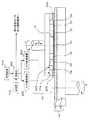
一方、ウェーハ研磨部は研磨ヘッドと支持部材とを備える。研磨ヘッド403は、図6に示すように、研磨定盤207の下面に研磨部材としての研磨パッド201を設けたものである。図6に示す例では、研磨パッド201として2層の多層パッドを用いているが、これに限定されるものではない。研磨ヘッド403は、アクチュエータとして電動モータを有する機構(図示せず)によって、図6の矢印G、H、Iで示す方向に回転、上下方向及び左右方向に揺動できるように支持されている。また、研磨定盤207も角度追従性を持つように支持されている。研磨パッド201の径は、ウェーハWの径よりも小さい。ウェーハWの研磨時に、研磨ヘッド403の矢印Iの方向の揺動によって、図6に示すように、研磨パッド201の一部が一時的にウェーハWの端部より図6に向かって右側の方へはみ出すことがある。図6は、研磨パッド201が最も右側へはみ出した状態を示している。なお、研磨ヘッド403はスラリー等の研磨助剤の供給機構(図示せず)を有しており、研磨定盤207の下面の回転中心に形成された給液孔から研磨パッド201及びウェーハWに研磨助剤を供給し得るように構成されている。 On the other hand, the wafer polishing unit includes a polishing head and a support member. As shown in FIG. 6, the polishing
支持部材404は、図6及び図7に示すように、真空チャック401に保持されたウェーハWの外周に若干の隙間Gをあけて沿うように円弧状をなし且つ断面長方形の単一の部材405(図7)で構成されている。因みに、部材405は単一の部材に代えて、例えば、積層された部材等の複合的な部材から構成されていても良い。この部材405の上面は、研磨パッド201がウェーハWのエッジからはみ出した部分を所定の圧力で押し上げる又は支持する支持面をなしており、全体に渡って同一の高さを持つ平面、即ち、真空チャック401に保持されたウェーハWの研磨対象面と実質的に平行な平面となっている。以下、研磨パッド201がウェーハWのエッジからはみ出した部分を支持部材が押し上げる圧力を「支持圧力」と呼ぶことにする。部材405は、例えば、ジルコニアやアルミナ等のセラミック材料や、エポキシ(EP)樹脂、フェノール(PF)樹脂、ポリフェニレンサルファイド(PPS)樹脂等のエンジニアリング・プラスチックで構成されることが望ましい。 As shown in FIGS. 6 and 7, the
第三の実施の形態には、図6に示すように、支持部材404における研磨パッド201がウェーハのエッジからはみ出した部分を支持する支持面の高さ(即ち、部材405の上面の図6における上下方向の位置)を調整して設定することができるよう、高さ調整機構406が設けられている。本実施の形態では、高さ調整機構406の下面は基部(ベース部材)407に固定され、その上面には、支持部材404に対して機械的に連結されていてウェーハWの研磨対象面を基準として支持部材404の支持面の高さを調整して設定し得る機構が設けられている。なお、図示のとおり、支持部材404は真空チャック401から独立した構成であり、真空チャック401と一緒に回転することはない。 In the third embodiment, as shown in FIG. 6, the height of the support surface that supports the portion of the
高さ調整機構406としては、精度の良好な周知の位置決め機構、例えば、ボールねじを使った精密位置決め機構を利用することができる。また、本実施の形態による研磨装置では、図6に示すように、真空チャック401に保持された状態におけるウェーハWの研磨対象面のロールオフ量に応じた情報を取得する測定部として、触針方式、光学方式、渦電流センサを含む電気方式、磁気方式、電磁方式、流体方式等の変位計103が設けられる。変位計103は、真空チャック401に保持されている研磨前のウェーハWの研磨対象面のロールオフ量を、真空チャック401におけるウェーハの研磨対象面の所定個所を基準点として計測する。ただし、ロールオフ量の上記測定方法はこれに限定されるものではなく、例えば、真空チャック401に保持される前のウェーハWのロールオフ量を測定してウェーハWのロールオフ量を得るようにしてもよい。このための測定器としては、例えば(株)コベルコ科研のエッジロールオフ測定装置(LER−100)などがある。また、研磨中のウェーハのロールオフ量を測定してもよい。ウェーハWの研磨対象面の高さは、本実施形態の研磨装置における真空チャック401や変位計103、エッジロールオフ測定装置におけるウェーハ保持面や測定部位などの幾何学的位置などを用いて、ウェーハWのロールオフ量から知ることができる。変位計103からの計測結果であるウェーハWの研磨対象面のロールオフ量は、制御部208により高さ調整機構406を制御するために用いられる。 As the
本発明の第三の実施の形態による研磨装置の動作は、制御部208によって制御される。つまり、制御部208は、前述した各部のモータ、変位計103、真空チャック401にウェーハWを受け渡す搬送ロボット(図示せず)、真空チャック401からウェーハWを引き取る搬送ロボット(図示せず)等を制御することによって、以下の動作を行う。図示しない搬送ロボットにより、ウェーハWが真空チャック401に受け渡されると、真空チャック401にウェーハWが保持された状態で、変位計103によりウェーハWの研磨対象面のロールオフ量が計測される。制御部208は、ウェーハWの研磨対象面のロールオフ量に基づいて高さ調整機構406を作動させ、支持部材404の支持面の高さを調整して所望の高さに設定する。支持部材404の支持面の高さの設定とそれによる効果については後述する。なお、部材405の支持面の高さを、ウェーハWの厚さを基準にして設定される高さからロールオフ量に応じた高さだけ補正することによって設定するようにしてもよい。 The operation of the polishing apparatus according to the third embodiment of the present invention is controlled by the
図6に示すように、ウェーハWの研磨は、研磨ヘッド403をウェーハWの研磨対象面に所定の圧力で押付けながら回転且つ揺動(すなわち走査)させることで実施される。真空チャック401を回転させながらウェーハWを回転させてウェーハWと研磨ヘッド403との間で相対運動を行わせている状態で、前述したように研磨助剤が研磨ヘッド403からウェーハW上に供給される。そのため、研磨助剤はウェーハW上で拡散し、研磨ヘッド403とウェーハWとの相対運動に伴って研磨パッド201とウェーハWとの間に入り込み、ウェーハWの研磨対象面を研磨する。換言すると、研磨ヘッド201とウェーハWとの相対運動による機械的研磨と研磨助剤の化学的作用とが相乗的に作用してウェーハWの研磨が行われる。なお、当業者には明らかなように、研磨助剤及び研磨パッド201の種類や、研磨ヘッド403及び真空チャック401の回転速度、研磨ヘッド403の揺動速度、揺動量等の研磨条件は研磨対象面の平坦化処理に適したものに設定される。 As shown in FIG. 6, the polishing of the wafer W is performed by rotating and swinging (that is, scanning) the polishing
なお、変位計103によって、研磨中のウェーハWの研磨対象面のロールオフ量を逐次測定し、その測定結果に合うように支持部材404の支持面の高さを調整して所望の高さに設定することも可能である。研磨が終了したウェーハWは搬送ロボット(図示せず)により洗浄工程等を行う場所に搬送される。 The
ここで、支持部材404の支持面の高さを設定するための方法の一例と、それによる効果について説明する。説明の便宜上、支持面の高さは、ウェーハWの中心部における研磨対象面の高さをゼロとし、研磨対象面の高さより研磨パッドの研磨面(換言すれば支持部材404の支持面)の方が高い(本実施の形態では上側にある)場合には+を、研磨対象面の高さより研磨パッドの研磨面(換言すれば支持部材404の支持面)の方が低い(本実施の形態では下側にある)場合には−を付すことにする。因みに、図8の横軸(支持面の高さ)の数値の符号はこの方法で付されている。 Here, an example of a method for setting the height of the support surface of the
まず、支持部材404の支持面の高さを設定する方法の一例について説明する。ウェーハWの研磨対象面のロールオフ量がウェーハ中心部でROQ0、ウェーハ・エッジから1mmの地点でROQ1であるとする。ROQ1はウェーハWの周方向の各点を平均した値でも、1点のみの値を代表値として用いてもよい。まず、ウェーハ・エッジから1mmの地点でのロールオフ量とウェーハ中心部でのロールオフ量の差△ROQ=ROQ1−ROQ0を算出する。次に、研磨後にエッジ・イクスクルージョンの内側が平坦な領域となるように、予め求めておいた△ROQと支持面の高さの関係に基づいて、算出した△ROQに対応する支持面の高さを求める。最後に、制御部208により支持部材404の支持面の高さを、上記により求めた高さに設定する。 First, an example of a method for setting the height of the support surface of the
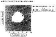
エッジ・イクスクルージョンの内側が平坦な領域となるように△ROQと支持面の高さとの関係を予め求める方法の一例を以下に説明する。図8は、△ROQ=0.5μmのウェーハにおいて、エッジ・イクスクルージョンを2mmとしたときの最大研磨レート及び最小研磨レートの相対値と支持面の高さとの関係を示すグラフである。通常の研磨においては幾何学的に完全に平坦な面を作成することは不可能であるが、例えばリソグラフィー・プロセスなどの半導体デバイス製造プロセスにおいて実用上十分な平坦度まで研磨すればウェーハの平坦度は十分である。このような実用上十分な平坦度に研磨された表面を「平坦な表面」であるとする。研磨レートのばらつきの許容値として適切な値を選ぶことにより、研磨後の研磨対象面が十分な平坦度となることが経験的に分かっているので、最大研磨レート及び最小研磨レートが共に研磨レートのばらつきの許容値内に入っていれば、エッジ・イクスクルージョンの内側は研磨後に実用上十分に平坦な領域となる。仮に、研磨レートのばらつきの許容値を研磨レートの相対値で1.0±0.1とすると、図8の場合、支持面の高さをおよそ−3.3μmから−3.7μmの範囲に入るようにすると、エッジ・イクスクルージョンの内側は平坦な領域となる。 An example of a method for obtaining in advance the relationship between ΔROQ and the height of the support surface so that the inside of the edge exclusion is a flat region will be described below. FIG. 8 is a graph showing the relationship between the relative values of the maximum polishing rate and the minimum polishing rate and the height of the support surface when the edge exclusion is 2 mm in a wafer with ΔROQ = 0.5 μm. Although it is impossible to create a geometrically perfectly flat surface in normal polishing, the flatness of a wafer can be achieved by polishing it to a practically sufficient flatness in a semiconductor device manufacturing process such as a lithography process. Is enough. A surface polished to such a practically sufficient flatness is assumed to be a “flat surface”. Since it has been empirically known that the surface to be polished after polishing has sufficient flatness by selecting an appropriate value as the tolerance of variation in the polishing rate, both the maximum polishing rate and the minimum polishing rate are the polishing rate. If it is within the tolerance value of the variation, the inside of the edge exclusion is a practically sufficiently flat region after polishing. If the allowable value of the polishing rate variation is 1.0 ± 0.1 as a relative value of the polishing rate, in the case of FIG. 8, the height of the support surface is in the range of about −3.3 μm to −3.7 μm. When entering, the inside of the edge exclusion is a flat area.
△ROQが異なれば、最大研磨レート及び最小研磨レートの相対値と支持面の高さとの関係も異なってくる。したがって、各△ROQにおける支持面の高さを上記のようにして求めれば、エッジ・イクスクルージョンの内側が平坦な領域となるように△ROQと支持面の高さとの関係を予め求めることができる。なお、全ての△ROQに対して支持面の高さを求めることは困難なため、実際には数点の△ROQに対して支持面の高さを求め、これらの点の間は補間式を用いて補間することになる。 If ΔROQ is different, the relationship between the relative values of the maximum polishing rate and the minimum polishing rate and the height of the support surface is also different. Therefore, if the height of the support surface at each ΔROQ is obtained as described above, the relationship between ΔROQ and the height of the support surface can be obtained in advance so that the inside of the edge exclusion is a flat region. it can. Since it is difficult to obtain the height of the support surface for all ΔROQs, the height of the support surface is actually obtained for several ΔROQs, and an interpolation formula is used between these points. Will be interpolated.
上述した支持面の高さの設定例では、ウェーハ・エッジから1mmの地点でのロールオフ量とウェーハ中心部でのロールオフ量との差△ROQを用いているが、支持面の高さの設定は、△ROQに限られるものではなく、ロールオフ量に基づいた情報であればよいので、非特許文献2に記載のROAであってもよいし、ロールオフ量を多項式などの近似式で近似したときの係数であってもよい。また、説明の便宜上、支持面の高さは、ウェーハWの中心部における研磨対象面の高さを基準としたが、ウェーハWの研磨対象面の任意の場所の高さを基準としてもよい。ただし、ウェーハWの研磨対象面が平坦であるとみなせる場所の高さを基準とすることが好ましい。 In the example of setting the height of the support surface described above, the difference ΔROQ between the roll-off amount at a
エッジ・イクスクルージョンの内側が平坦な領域となるように予め求めた△ROQと支持面の高さとの関係に関する情報は、記憶媒体209に記憶される。制御部208は、記憶媒体209に記憶されている上記情報にアクセスするためのプログラムを備えることにより、変位計103により取得したウェーハWの研磨対象面のロールオフ量の測定結果に基づいて支持面の高さを制御する。記憶媒体209には、前述の情報やプログラムの他に、変位計103により取得したウェーハWの研磨対象面のロールオフ量の測定結果に基づいて支持面の高さを制御するためのプログラムを記憶させておいてもよい。また、記憶媒体209には、前述した各部のモータ、変位計103及び搬送ロボットを制御するためのプログラムを記憶させておくことができる。記憶媒体209は制御部208と物理的に独立していても、制御部208の中に物理的に組み込まれていてもよい。 Information relating to the relationship between ΔROQ and the height of the support surface obtained in advance so that the inside of the edge exclusion is a flat region is stored in the
このようにして支持部材404の支持面の高さを設定すると、研磨時において、研磨ヘッド403の研磨パッド201のリバウンドによるウェーハWへの影響が低減され、この点からエッジ・イクスクルージョンを小さくすることができると共に、ロールオフ量に拘わらず、ウェーハの平坦研磨が可能となる。また、研磨ヘッド403の傾きも実質的に生じないので、エッジ・ファーストが低減され、これによってもエッジ・イクスクルージョンが小さくなる。 When the height of the support surface of the
本発明の第三の実施の形態においては、変位計103によって取得されたウェーハWの研磨対象面のロールオフ量に基づいて、支持部材404の高さが調整されるので、個々のウェーハWのロールオフのばらつきにも拘わらず、ウェーハWの研磨対象面を基準として支持部材404の高さを所望の高さに設定することができ、所定の効果を適切に奏することができる。即ち、研磨ヘッド403の研磨パッド201のリバウンドによるウェーハWへの影響を、ウェーハWのロールオフ量のばらつきに応じて最適化して低減することができる。 In the third embodiment of the present invention, since the height of the
本発明の第三の実施の形態においては、真空チャック401に対して研磨ヘッド403の研磨パッド201がウェーハWからはみ出す箇所にのみ支持部材404が設けられているが、例えば、支持部材404に代えて、真空チャック401に保持されるウェーハWの外周全体に沿ってリング状に配置した支持部材を設けてもよい。この場合、この支持部材は、前述の支持部材と同様に、真空チャック401と独立し且つ真空チャック401と共に回転しないようにしても、真空チャック401と共に回転するようにしてもよい。後者の場合、支持部材に対して設けられる高さ調整機構406に相当する高さ調整機構のベースを、真空チャック401に対して固定すればよい。 In the third embodiment of the present invention, the
図9の(a)及び(b)は、本発明に係る研磨装置の第四の実施の形態における研磨部の支持部材とウェーハWとを模式的に示す図であり、図7に対応している。以下、本発明の第四の実施の形態が前述の第三の実施の形態と異なる所について説明する。 FIGS. 9A and 9B are diagrams schematically showing a support member of the polishing unit and the wafer W in the fourth embodiment of the polishing apparatus according to the present invention, and correspond to FIG. Yes. Hereinafter, the fourth embodiment of the present invention will be described where the third embodiment is different from the third embodiment.
第四の実施の形態においては、図7に示す支持部材404に代えて、ウェーハWの周囲へはみ出す研磨パッド201の部分を支持するために、図9の(a)及び(b)に示すように、ウェーハWの周囲を囲むように順次配置され且つ互いに120゜の間隔で分離された3つの独立した支持要素501a、501b、501cで構成されたリング状の支持部材501を用いている。支持要素501aは、図9の(a)に示すように、真空チャック401に保持されたウェーハWの外周に内周面が適合する円弧状をなし断面長方形の単一の部材で構成されている。支持部材501aの上面は、研磨パッド201がウェーハWのエッジからはみ出した部分を支持する支持面の一部をなし、全体に渡って同一の高さを持つ平面、即ち、真空チャック401におけるウェーハ保持面と実質的に同じ平面をなす。他の支持要素501b、501cも支持要素501aと同様に構成される。 In the fourth embodiment, instead of the
支持部材501が上記のように構成されているため、それぞれの支持要素501a〜501cに対して、対応する支持要素の上面の高さを独立して調整して設定し得る、図6の高さ調整機構406に相当する高さ調整機構に加えて、移動機構(図示せず)が設けられる。各移動機構は、対応する支持要素を図9(a)に示す第一の位置と図9(b)に示す第二の位置とに保持できるよう、ウェーハWを中心にウェーハWの研磨対象面に平行に且つ放射方向に支持要素を移動させるように構成されている。なお、この実施の形態における高さ調整機構及び移動機構は周知の位置決め機構により構成することができる。 Since the
支持要素501aに対して設けられた移動機構は、真空チャック401又は軸402に直接又は間接的に固定されたベース部と、支持要素501aに対して設けられた高さ調節機構を固定する可動部とを備えている。また、支持要素501aに対して設けられた高さ調節機構は、支持要素501aに対して設けられた移動機構に直接又は間接的に固定されたベース部と、支持要素501aを固定する可動部とを備えている。したがって、本実施の形態では、支持要素501a、移動機構及び高さ調整機構は、真空チャック401と一緒に回転する。支持要素501b、501cに設けられた移動機構、高さ調節機構もそれぞれ個別に同様に構成される。それぞれの移動機構及び高さ調整機構の動作は制御部208によって制御される。 The moving mechanism provided for the
本発明の第四の実施の形態においては、それぞれの支持要素501a〜501cが図9(b)に示すように前記第二の位置に移動された状態で、図示しない搬送ロボットにより、ウェーハWが真空チャック401にローディングされる。このため、支持要素501a〜501cがウェーハWのローディングの邪魔にならない。真空チャック401にウェーハWが保持された状態で、変位計103によりウェーハWの研磨対象面のロールオフ量が計測される。制御部208は、ウェーハWの研磨対象面のロールオフ量に基づく情報により支持要素501a〜501cに対応して設けられた高さ調整機構をそれぞれ作動させ、支持要素501a〜501cの上面の高さをそれぞれ調整して所望の高さに設定する。これらの高さの設定の仕方は、本発明の第三の実施の形態において支持部材404の高さの設定と同様である。その後、制御部208は各移動機構を制御し、支持要素501a〜501cを図9(a)に示す第一の位置に移動させる。その結果、支持要素501a〜501cの内周側とウェーハWの外周との間には実質的に隙間がなくなる。この状態は研磨が終了するまで維持される。 In the fourth embodiment of the present invention, each
次いで、研磨による平坦化処理が行われる。研磨が終了したウェーハWがアンロードされ、搬送ロボット(図示せず)により洗浄工程等を行う図示しない場所に搬送される。このウェーハWのアンローディングは、各支持要素501a〜501cが図9(b)に示すように前記の第二の位置に移動された状態で行われる。このため、各支持要素501a〜501cがウェーハWのアンローディングの邪魔になるようなことがないので、ウェーハのアンローディングが容易となる。 Next, a planarization process by polishing is performed. The polished wafer W is unloaded and transferred to a place (not shown) where a cleaning process or the like is performed by a transfer robot (not shown). The unloading of the wafer W is performed in a state where the
以上の説明から理解されるように、本発明の第四の実施の形態も前述の第三の実施の形態と同等の効果を奏する。更に、第四の実施の形態によれば、第三の実施の形態に比べて、ウェーハWの外縁で生ずる研磨パッド201のリバウンドの影響を低減することができる。即ち、第三の実施の形態では、支持部材404とウェーハWとの間に隙間G(図6参照)が生じているので、この隙間のために、少ないながらも、ウェーハWの外縁で生ずる研磨パッド201のリバウンドの影響が生じる。これに対し、第四の実施の形態では、研磨は、図9の(a)に示すように、支持要素501a〜501cの内周とウェーハWの外周との間に実質的に隙間がない状態で行われるので、ウェーハWの外縁で生ずる研磨パッド201のリバウンドの影響を更に低減することができ、エッジ・イクスクルージョンを一層小さくすることができ、ウェーハ研磨後の平坦度を一層向上させることができる。また、第四の実施の形態によれば、ウェーハWのローディング及びアンローディングは、図9(b)に示すように、支持要素501a〜501cがウェーハWの外周から離れた状態で行われるので、ウェーハWのローディング及びアンローディングを容易に行うことができる。 As can be understood from the above description, the fourth embodiment of the present invention also has the same effect as the above-described third embodiment. Furthermore, according to the fourth embodiment, it is possible to reduce the influence of the rebound of the
なお、支持要素501a〜501cの上面の高さを、ウェーハWの図9(b)に示した対応の領域Wa、Wb、Wcのロールオフ量に基づいた情報によりそれぞれ調整して所望の高さに設定することにより、ロールオフの周方向のばらつきの影響を軽減することが可能である。例えば、ウェーハWの領域Waの研磨対象面上の任意の位置における△ROQに対応する支持面の高さに、支持要素501aの高さを設定する。同様に、ウェーハWの領域Wbの研磨対象面上の任意の位置における△ROQに対応する支持面の高さに支持要素501bの高さを設定し、ウェーハWの領域Wcの研磨対象面上の任意の位置における△ROQに対応する支持面の高さに支持要素501cの高さを設定する。ただし、支持面の高さを△ROQによって設定する代わりに、ロールオフ量に基づいた情報によって支持面の高さを制御してもよく、任意の方法を用いることができる。例えば、ウェーハWの領域Waの研磨対象面のロールオフ量から算出した複数の△ROQの平均値に対応する支持面の高さに設定しても、ウェーハWの領域Waの任意の位置でのROAに対応する支持面の高さに設定しても、また、ウェーハWの領域Waの複数のROAの平均値に対応する支持面の高さに設定してもよい。これらの点は、後述する各実施の形態についても同様である。 It should be noted that the heights of the upper surfaces of the
更に、図10に示すように、それぞれの支持要素501a〜501cを、独立して支持面の高さを制御可能な複数の支持片501a1〜501a4、501b1〜501b4、501c1〜501c4からなる部材として構成することも可能である。これにより、ロールオフの周方向のばらつきによる研磨量のばらつきを一層抑制することが可能となる。図10に示す場合も、それぞれの支持要素501a〜501cを構成する支持片501a1〜501a4、501b1〜501b4、501c1〜501c4は、図9(a)に示す第一の位置と図9(b)に示す第二の位置とに選択的に保持されるよう、ウェーハWを中心にウェーハWの研磨対象面に沿って放射方向に移動させるための移動機構を備えている。同様に、支持片501a1〜501a4、501b1〜501b4、501c1〜501c4のそれぞれは、その支持面の高さを独立して設定するための高さ調整機構を備えている。前記のとおり、こうした高さ調整機構及び移動機構は周知の位置決め機構により構成することができる。 Furthermore, as shown in FIG. 10, each
図11は、本発明に係る研磨装置の第五の実施の形態における研磨部の断面とその制御系統とを模式的に示す図であり、図6に対応している。図11において、図6に示す構成要素と同一又は対応する構成要素には同一符号を付すこととし、その重複する説明は省略する。図11は研磨パッド201が最も右側へはみ出した時の状態を示している。 FIG. 11 is a diagram schematically showing a cross section of a polishing portion and its control system in the fifth embodiment of the polishing apparatus according to the present invention, and corresponds to FIG. In FIG. 11, the same or corresponding components as those shown in FIG. 6 are denoted by the same reference numerals, and redundant description thereof is omitted. FIG. 11 shows a state when the
以下、本発明の第五の実施の形態が図6により説明した第三の実施の形態と異なる点について説明する。図6の第三の実施の形態では、ウェーハWの研磨対象面のロールオフ量に基づいた情報により、支持部材404の支持面の高さを所望の高さとして、ロールオフのばらつきによる研磨量のばらつきを低減している。これに対し、図11の第五の実施の形態においては、ウェーハWの研磨対象面のロールオフ量に基づいた情報を用いて支持部材404が研磨パッドに印加する支持圧力を圧力調整機構601により所望の圧力に設定することにより、ロールオフのばらつきによる研磨量のばらつきを低減する。 Hereinafter, the difference of the fifth embodiment of the present invention from the third embodiment described with reference to FIG. 6 will be described. In the third embodiment of FIG. 6, the amount of polishing due to variations in roll-off is determined by setting the height of the support surface of the
圧力調整機構601の一例を図12に示す。図12においては、圧力調整機構601は、ベース部材407に固定された空気圧シリンダ602と、空気圧シリンダ602のロッド603から構成され、ロッド603の一端は支持部材404に連結されている。支持部材404の一方の側面は、支持部材404をロッド603の軸方向に案内するためのガイド部材604に結合されている。圧力調整機構601により、支持部材404を研磨パッド201に押付ける支持圧力を所望の値になるよう調節することができる。なお、圧力調整機構601の構成は図12に示すものに限定されるものではなく、種々の機構を採用し得る。 An example of the
図11に示す第五の実施の形態において支持部材404の支持圧力は、既述の第一の実施の形態におけると同様の方法で設定することができ、制御部208は、研磨パッド201がウェーハWからはみ出した場合に支持部材404の支持圧力を所定の面圧に設定する。しかし、研磨パッド201がウェーハWからはみ出していないときには支持圧力を加える必要が無く、圧力調整機構601により支持部材404の支持面の高さをウェーハWとほぼ同一に保持しておけばよい。 In the fifth embodiment shown in FIG. 11, the support pressure of the
エッジ・イクスクルージョンの内側が平坦な領域となるように△ROQと支持圧力との関係を予め求めるために、既に第一の実施の形態について説明したのと同じ方法を用いることができる。エッジ・イクスクルージョンの内側が平坦な領域となるように予め求めておいた△ROQと支持圧力との関係に関する情報は、第一の実施の形態と同様に、記憶媒体209に記憶されている。制御部208は、記憶媒体209に記憶されているエッジ・イクスクルージョンの内側が平坦な領域となるように予め求めておいた、△ROQと支持圧力との関係に関する情報にアクセスすることにより、変位計103により取得したウェーハWの研磨対象面のロールオフ量の測定結果に基づいて支持圧力を制御する。記憶媒体209に記憶される情報は第一の実施の形態について述べたとおりである。前記のとおり、記憶装置209は制御部208と物理的に独立して設置されても、制御部209の中に物理的に組み込まれて設置されてもよい。 In order to obtain in advance the relationship between ΔROQ and the support pressure so that the inside of the edge exclusion is a flat region, the same method as already described in the first embodiment can be used. Information about the relationship between ΔROQ and the support pressure, which has been obtained in advance so that the inside of the edge exclusion is a flat region, is stored in the
本発明の第五の実施の形態においても、第一の実施の形態と同様に、研磨ヘッド403の研磨パッド201のリバウンドによるウェーハWへの影響の低減効果を、ウェーハWのロールオフ量のばらつきに応じて最適化して得ることができる。 Also in the fifth embodiment of the present invention, as in the first embodiment, the effect of reducing the influence on the wafer W due to the rebound of the
ここで、図13を用いて本発明に係る研磨装置の第六の実施の形態を説明する。この第六の実施の形態は、図9を用いて説明した第四の実施の形態による研磨装置において、各支持要素501a〜501cの支持面の高さを調整する高さ調整機構の代わりに圧力調整機構を設けるようにしたものである。第六の実施の形態が図9の第四の実施の形態と異なる点について以下説明する。第四の実施の形態では、ウェーハWの研磨対象面のロールオフ量に基づいた情報により、各支持要素501a〜501cの支持面の高さを所望の高さに設定してロールオフのばらつきによる研磨量のばらつきを低減するようにしていた。これに対し、図13に示す第六の実施の形態においては、ウェーハWの研磨対象面のロールオフ量に基づく情報によって、各支持要素501a〜501cが研磨パッドに加える支持圧力をそれぞれの支持要素に対応して設けられた圧力調整機構によって所望の圧力に設定し、ロールオフのばらつきによる研磨量のばらつきを低減するようにしている。なお、ウェーハWの研磨対象面のロールオフ量に基づく情報によって各支持要素501a〜501cの支持圧力を所望の圧力に設定する方法は、第一の実施の形態、第二の実施の形態及び第五の実施の形態について説明したのと同様である。 Here, a sixth embodiment of the polishing apparatus according to the present invention will be described with reference to FIG. In the sixth embodiment, in the polishing apparatus according to the fourth embodiment described with reference to FIG. 9, pressure is used instead of the height adjustment mechanism that adjusts the height of the support surface of each of the
図13は、本発明に係る研磨装置の第六の実施の形態における移動機構及び圧力調整機構の構成の一例を示す図であり、支持要素501a〜501cのうちの支持要素501aに対して移動機構701と圧力調整機構702とを設けた例を示している。他の支持要素501b、501cに対しても同様の機構が設けられる。 FIG. 13 is a diagram showing an example of the configuration of the moving mechanism and the pressure adjusting mechanism in the sixth embodiment of the polishing apparatus according to the present invention, and the moving mechanism with respect to the
支持要素501aに対して設けられた移動機構701は、エアシリンダ703と連結部材704とストッパ705とから構成されている。エアシリンダ703のシリンダ本体706は、ベース部材407によって案内されて図13の左右方向即ちウェーハWの径方向に移動できるように構成されている。連結部材704はエアシリンダ703のピストン・ロッド707の先端とベース部材407とを連結する。連結部材704はシリンダ本体706の図13における右方向への移動を規制するストッパを兼ねている。シリンダ本体706が連結部材704によって規制される位置は図9の(b)に示す第二の位置に相当する。ストッパ705はベース部材407に固定され、シリンダ本体706の図13における左方向への移動を規制するよう動作する。シリンダ本体706がストッパ705で規制される位置は図9の(a)に示す第一の位置に相当する。 The moving
シリンダ本体706内のピストン708によって画成される両側の気密室709、710には、それぞれ図示しない通気路が連通しており、これらの通気路を利用して、切替弁(図示せず)により、気密室709を真空に引くとともに気密室710を大気に解放して、支持要素501a〜501cのそれぞれを前記の第一の位置(シリンダ本体706がストッパ705に当接する位置)まで移動させた状態と、気密室709を大気に解放するとともに気密室710を真空に引いて支持要素501a〜501cを前記の第二の位置(シリンダ本体706が連結部材704に当接する位置)まで移動させた状態とを切り替えることができる。 The
図13に示す構成において、圧力調整機構702は、シリンダ本体706に固定された空気圧シリンダ711と、空気圧シリンダ711のロッド712と、支持要素501aの上下方向の移動を案内するガイド713とを備えており、ロッド712の上端は支持要素501aに固定される。このように圧力調整機構702を設けているので、支持要素501aが研磨パッド201を押し上げる支持圧力を所望の値に調節して設定することができる。なお、圧力調整機構702の構成は図13に示すものに限定されるものではなく、他の種々の機構を採用し得る。 In the configuration shown in FIG. 13, the
図13に示す第六の実施の形態も図11の第五の実施形態と同様の効果を奏する。更に、第六の実施の形態によれば、第五の実施形態に比べて、ウェーハWの外縁で生ずる研磨パッドのリバウンドの影響を低減することができる。即ち、第五の実施の形態では、支持部材404とウェーハWとの間に隙間Gが生じ、この隙間のために、少ないながらも、ウェーハWの外縁で生ずる研磨パッドのリバウンドの影響が生じる。これに対し、第六の実施の形態では、第四の実施の形態と同様に、それぞれの支持要素501a〜501cの内周側とウェーハWの外周との間には実質的に隙間がないので、ウェーハWの外縁で生ずる研磨パッドのリバウンドの影響を更に低減することができ、エッジ・イクスクルージョンをより小さくすることができる。また、第六の実施の形態によれば、第四の実施形態と同様に、ウェーハWのローディング及びアンローディングが容易である。それぞれの支持要素501a〜501cの支持圧力を、第四の実施の形態と同様に、ウェーハWの図9(b)に示す各領域Wa〜Wcにおけるロールオフ量に基づく情報によりそれぞれ調整して所望の圧力に設定することにより、ロールオフの周方向のばらつきによる影響も軽減される。 The sixth embodiment shown in FIG. 13 has the same effect as the fifth embodiment shown in FIG. Furthermore, according to the sixth embodiment, it is possible to reduce the influence of the rebound of the polishing pad generated at the outer edge of the wafer W, as compared with the fifth embodiment. In other words, in the fifth embodiment, a gap G is generated between the
加えて、第四の実施形態のように、各支持要素501a〜501cを、独立して支持圧力を制御することができる複数の支持要素から構成し、各支持要素に圧力調整機構を設けることにより、ロールオフ量の周方向のばらつきによる研磨量のばらつきを、より抑制することが可能となる。 In addition, as in the fourth embodiment, each of the
図14は、本発明に係る研磨装置の第七の実施の形態における研磨部の断面とその制御系統とを模式的に示す図である。図2に示す第一の実施の形態と同様に、研磨部はトップリングと研磨テーブルとを備える。図14は、トップリング52及び研磨テーブル54の一部の断面と制御系統の一例とを模式的に示している。図14において、図2における構成要素と同一又は対応する構成要素には同一符号を付すこととし、それらについての重複する説明は省略する。そこで、以下では、本発明の第七の実施の形態が第一の実施の形態と異なる点を中心にして説明する。 FIG. 14 is a diagram schematically showing a cross section of a polishing unit and its control system in the seventh embodiment of the polishing apparatus according to the present invention. As in the first embodiment shown in FIG. 2, the polishing unit includes a top ring and a polishing table. FIG. 14 schematically shows a partial cross section of the
まず、第七の実施の形態では、トップリング52が、図2における単一のエアバッグ202の代わりに、同心円状に複数の区画に分かれたエアバッグ802を有しており、プロファイル・コントロール型トップリングとなっている。トップリング52は、中心の円盤状のエアバックZ1、該エアバックZ1を囲むドーナツ状のエアバックZ2、該エアバックZ2を囲むドーナツ状のエアバックZ3、該エアバックZ3を囲むドーナツ状のエアバックZ4の4つエアバッグを有している。それぞれのエアバッグのエア圧力を調節することにより、それぞれが担当するウェーハWのエリアに対する押付け圧力を独立して調節可能である。ウェーハWのエッジ部分の研磨レートを下げたい場合には、圧力調整機構806によってエアバッグZ4のエア圧力を下げ、エッジ部分を担当する押圧部分の押付け圧力を小さくすれば良い。なお、押付け圧力は、通常エア圧力とほぼ同じ圧力となる。 First, in the seventh embodiment, the
このように、図14に示すようなプロファイル・コントロール型トップリングを用いれば、それぞれのエアバッグのエア圧力を調節することにより、研磨レートの半径方向分布を制御することができる。したがって、ウェーハのエッジ部分を担当する押圧部分(エッジエリア)の押付け圧力をロールオフに応じて調節すれば、ロールオフのばらつきに対応することができる。 As described above, when the profile control type top ring as shown in FIG. 14 is used, the radial distribution of the polishing rate can be controlled by adjusting the air pressure of each airbag. Therefore, if the pressing pressure of the pressing portion (edge area) responsible for the edge portion of the wafer is adjusted according to the roll-off, it is possible to cope with the roll-off variation.
ここで、エッジエリアの押付け圧力、すなわちエアバッグZ4のエア圧力を設定する方法の一例を説明する。なお、説明の便宜上、エッジエリアを除く押圧部分の押付け圧力(すなわち、エアバッグZ1、Z2、Z3の各エア圧力)とリテーナリングによる押圧面圧力は同一とし、エッジエリアの押付け圧力は、その圧力に対する相対値として表すこととする。ウェーハWの研磨対象面のロールオフ量がウェーハ中心部ではROQ0、ウェーハ・エッジから1mmの地点でROQ1であるとする。ROQ1として、ウェーハWの周方向の各点を平均した値を用いても、1つの点のみの値を代表値として用いてもよい。 Here, an example of a method for setting the pressing pressure of the edge area, that is, the air pressure of the airbag Z4 will be described. For convenience of explanation, the pressing pressure of the pressing portion excluding the edge area (that is, each air pressure of the airbags Z1, Z2, and Z3) and the pressing surface pressure by the retainer ring are the same, and the pressing pressure of the edge area is the pressure. It will be expressed as a relative value to. Assume that the roll-off amount of the polishing target surface of the wafer W is ROQ0 at the center of the wafer and ROQ1 at a
まず、ウェーハ・エッジから1mmの地点でのロールオフ量とウェーハ中心部でのロールオフ量との差△ROQ=ROQ1−ROQ0を算出する。次に、研磨後にエッジ・イクスクルージョンの内側が平坦な領域となるように、予め求めておいた△ROQとエッジエリア押付け圧力との関係に基づいて、算出した△ROQに対応する押付け圧力を求める。最後に、制御部208によって、エアバッグZ4のエア圧力を上記により求めた圧力に設定する。 First, the difference ΔROQ = ROQ1−ROQ0 between the roll-off amount at a
ここで、エッジ・イクスクルージョンの内側が平坦な領域となるように△ROQとエッジエリア押付け圧力との関係を予め求める方法の一例を説明する。図15は、△ROQ=0.5μmのウェーハにおいて、エッジ・イクスクルージョンを2mmとしたときの最大研磨レート及び最小研磨レートの相対値とエッジエリアの押付け圧力との関係を示している。通常の研磨においては、幾何学的に完全に平坦な面は作成不可能であるが、例えばリソグラフィー・プロセスなどの半導体デバイス製造プロセスにおいては、実用上十分な平坦度まで研磨できれば十分である。そこで、以下の説明においては、このような実用上十分な平坦度に研磨された表面を「平坦な表面」であるとする。また、研磨レートのばらつきの許容値として適切な値を選ぶことにより、研磨後の研磨対象面を十分な平坦度とすることできるということが経験的に分かっている。したがって、最大研磨レート及び最小研磨レートが共に研磨レートのばらつきの許容値内に入っていれば、エッジ・イクスクルージョンの内側は研磨後には平坦な領域となると言える。したがって、図15の場合、研磨レートのばらつきの許容値を研磨レートの相対値で例えば1.0±0.1とすると、エッジエリアの押付け圧力を研磨圧力に対しておよそ0.80倍から0.94倍の間に設定すれば、エッジ・イクスクルージョンの内側は平坦な領域となることが分かる。 Here, an example of a method for obtaining in advance the relationship between ΔROQ and the edge area pressing pressure so that the inside of the edge exclusion is a flat region will be described. FIG. 15 shows the relationship between the relative values of the maximum polishing rate and the minimum polishing rate and the pressing pressure in the edge area when the edge exclusion is 2 mm in a wafer of ΔROQ = 0.5 μm. In normal polishing, it is impossible to create a geometrically completely flat surface. However, in a semiconductor device manufacturing process such as a lithography process, it is sufficient that polishing can be performed to a sufficiently flatness for practical use. Therefore, in the following description, it is assumed that the surface polished to such a practically sufficient flatness is a “flat surface”. Further, it has been empirically known that the surface to be polished after polishing can have a sufficient flatness by selecting an appropriate value as an allowable value of variation in polishing rate. Therefore, if the maximum polishing rate and the minimum polishing rate are both within the allowable value of variation in the polishing rate, it can be said that the inside of the edge exclusion is a flat region after polishing. Therefore, in the case of FIG. 15, if the allowable value of the polishing rate variation is, for example, 1.0 ± 0.1 as a relative value of the polishing rate, the pressing pressure of the edge area is about 0.80 times to 0 with respect to the polishing pressure. It can be seen that if it is set to .94 times, the inside of the edge exclusion is a flat area.
△ROQが異なれば、最大研磨レート及び最小研磨レートの相対値とエッジエリア押付け圧力との関係も異なってくる。したがって、各△ROQにおけるエッジエリアの押付け圧力を上記のようにして求めておけば、エッジ・イクスクルージョンの内側が平坦な領域となるように△ROQとエッジエリア押付け圧力との関係を予め求めることができる。しかし、全ての△ROQに対してエッジエリア押付け圧力を求めることは困難なため、実際には、数点の△ROQに対してエッジエリア押付け圧力を求め、それらの点間を補間式を用いて補間することになる。 When ΔROQ is different, the relationship between the relative values of the maximum polishing rate and the minimum polishing rate and the edge area pressing pressure is also different. Therefore, if the edge area pressing pressure at each ΔROQ is determined as described above, the relationship between ΔROQ and the edge area pressing pressure is determined in advance so that the inside of the edge exclusion is a flat region. be able to. However, since it is difficult to obtain the edge area pressing pressure for all ΔROQ, the edge area pressing pressure is actually obtained for several ΔROQ and an interpolation formula is used between these points. Will be interpolated.
上述のエッジエリア押付け圧力の設定例では、ウェーハ・エッジから1mmの地点でのロールオフ量とウェーハ中心部でのロールオフ量との差△ROQを用いている。しかし、エッジエリア押付け圧力の設定は前述の△ROQに限られるものではなく、ロールオフ量に基づいた情報であれば、非特許文献2に記載のROAであってもよいし、ロールオフ量を多項式等の近似式で近似したときの係数であってもよい。 In the above-described setting example of the edge area pressing pressure, the difference ΔROQ between the roll-off amount at a
エッジ・イクスクルージョンの内側が平坦な領域となるように予め求めておいた△ROQとエッジエリア押付け圧力との関係に関する情報は、記憶媒体209に記憶される。そこで、制御部208は、記憶媒体209に記憶されている、エッジ・イクスクルージョンの内側が平坦な領域となるように予め求めた△ROQとエッジエリア押付け圧力との関係に関する情報と、それにアクセスするためのプログラムとにより、変位計103により取得されたウェーハWの研磨対象面のロールオフ量の測定結果に基づいて、エッジエリア押付け圧力を制御する。記憶媒体209には、前述の情報やプログラムの他に、変位計103により取得されたウェーハWの研磨対象面のロールオフ量の測定結果に基づいてエッジエリア押付け圧力を制御するためのプログラムを記憶させてもよい。また、記憶媒体209には、前述した各部のモータ、変位計103及び搬送ロボットを制御するためのプログラムを記憶させておくことができる。記憶媒体209は制御部208と物理的に独立していても、制御部208の中に物理的に組み込まれていてもよい。 Information regarding the relationship between ΔROQ and the edge area pressing pressure, which has been obtained in advance so that the inside of the edge exclusion is a flat region, is stored in the
以上説明したところから理解されるように、本発明の第七の実施の形態においては、研磨パッド201のリバウンドによるウェーハWへの影響を、ウェーハWのロールオフ量のばらつきに応じて最適化することによって低減することができる。 As can be understood from the above description, in the seventh embodiment of the present invention, the influence on the wafer W due to the rebound of the
なお、上述の説明では、同心円状に区画された4つのエアバックを有するトップリングを用いて説明した。しかし、プロファイル・コントロール型トップリングは、複数の押圧部分を有するトップリングの総称である。即ち、複数のメンブレンで同心円状に区画されたエアバックやウォータバックによる複数の押圧部分を有するもの、区画された空気室に個別に加圧することによりウェーハ裏面を空気圧で直接押圧する部分を複数有するもの、圧力をばねによって発生させる部分を有するもの、1つ又は複数の圧電素子を配置して局所的な押圧部分を有するものや、これらを組み合わせたものがプロファイル・コントロール型トップリングとして使用される。 In the above description, a top ring having four airbags concentrically divided is used. However, the profile control type top ring is a general term for a top ring having a plurality of pressing portions. That is, it has a plurality of pressing portions by air bags and water bags concentrically divided by a plurality of membranes, and a plurality of portions that directly press the back surface of the wafer by air pressure by individually pressurizing the partitioned air chambers One having a part for generating pressure by a spring, one having a local pressing part by arranging one or a plurality of piezoelectric elements, or a combination thereof is used as a profile control type top ring .
ここで、エアバックとはウェーハを押し付ける空気による背圧を意味し、印加手段としてはエアバッグに限られない。同様に、ウォータバックとはウェーハを押し付ける液体(水)による背圧を意味し、印加手段としてはウォータバッグに限られない。 Here, the air bag means a back pressure by the air pressing the wafer, and the application means is not limited to the airbag. Similarly, the water back means a back pressure caused by a liquid (water) pressing the wafer, and the application means is not limited to the water bag.
図16は、本発明に係る研磨装置の第八の実施の形態における研磨部の断面とその制御系統とを模式的に示す図である。本発明の第八の実施の形態は、第一の実施の形態と第七の実施の形態とを組み合わせた形態となっている。すなわち、本発明の第八の実施の形態は、ロールオフのばらつきによる研磨レートのばらつきを、リテーナリングの押圧面圧力とエッジエリアの押付け圧力の両方を調節して最適化することにより、低減することができる。 FIG. 16 is a diagram schematically showing a cross section of a polishing portion and its control system in the eighth embodiment of the polishing apparatus according to the present invention. The eighth embodiment of the present invention is a combination of the first embodiment and the seventh embodiment. In other words, the eighth embodiment of the present invention reduces the polishing rate variation due to the roll-off variation by adjusting both the pressing surface pressure of the retainer ring and the pressing pressure of the edge area. be able to.
ここで、リテーナリング203の押圧面圧力とエッジエリアの押付け圧力(すなわちエアバッグZ4のエア圧力)を設定する方法の一例を説明する。ウェーハWの研磨対象面のロールオフ量がウェーハ中心部ではROQ0、ウェーハ・エッジから1mmの地点でROQ1であるとする。ROQ1として、ウェーハWの周方向の各点を平均した値を用いても、1つの点のみの値を代表値として用いてもよい。 Here, an example of a method for setting the pressing surface pressure of the
まず、ウェーハ・エッジから1mmの地点でのロールオフ量とウェーハ中心部でのロールオフ量との差△ROQ=ROQ1−ROQ0を算出する。次に、研磨後にエッジ・イクスクルージョンの内側が平坦な領域となるように、予め求めておいた△ROQとリテーナリングの押圧面圧力及びエッジエリア押付け圧力との関係に基づいて、算出した△ROQに対応するリテーナリング203の押圧面圧力とエッジエリアの押付け圧力を求める。最後に、制御部208によって、リテーナリング203の押圧面圧力とエアバッグZ4のエア圧力を上記により求めた圧力に設定する。 First, the difference ΔROQ = ROQ1−ROQ0 between the roll-off amount at a
ここで、エッジ・イクスクルージョンの内側が平坦な領域となるように△ROQとリテーナリングの押圧面圧力及びエッジエリアの押付け圧力との関係を予め求める方法の一例を説明する。図17は、△ROQ=0.5μmのウェーハにおいて、エッジ・イクスクルージョンを2mmとしたときの最大研磨レート及び最小研磨レートの相対値が、研磨レートのばらつきの許容値1.0±0.1に入るリテーナリングの押圧面圧力とエッジエリア押付け圧力との関係を示している。図17は、エッジエリアを除く押圧部分の押付け圧力(すなわち、エアバッグZ1、Z2、Z3の各エア圧力)を同一とし、リテーナリングの押圧面圧力とエッジエリアの押付け圧力を変化させて関係を求めた図である。 Here, an example of a method for obtaining in advance the relationship between ΔROQ, the pressing surface pressure of the retainer ring, and the pressing pressure of the edge area so that the inside of the edge exclusion is a flat region will be described. FIG. 17 shows that for a wafer with ΔROQ = 0.5 μm, the relative values of the maximum polishing rate and the minimum polishing rate when the edge exclusion is 2 mm are the allowable values of polishing rate variation of 1.0 ± 0. The relationship between the pressing surface pressure of the retainer ring which enters 1 and the edge area pressing pressure is shown. FIG. 17 shows the relationship between the pressing pressures of the pressing portions excluding the edge area (that is, the air pressures of the airbags Z1, Z2, and Z3), and the pressing surface pressure of the retainer ring and the pressing pressure of the edge area are changed. FIG.
具体的には、まず、リテーナリングの押圧面圧力とエッジエリアの押付け圧力の組み合わせを実験計画法により計画する。次に、各組み合わせにおける面圧分布を、有限要素法を用いた数値解析により求め、エッジ・イクスクルージョンの内側の最小相対面圧と最大相対面圧を求める。ここで求めた最小相対面圧及び最大相対面圧が、それぞれ最小研磨レートの相対値及び最大研磨レートの相対値となる。次に、応答曲面法により最小研磨レーとの相対値及び最大研磨レートの相対値が共に1.0±0.1に入るリテーナリングの押圧面圧力とエッジエリアの押付け圧力を求める。以上の手順において、実験計画法及び応答曲面法には、実験計画法を実行可能な市販ソフト(例えば、Minitab Inc.社MINITAB等)を使用することができる。 Specifically, first, the combination of the pressing surface pressure of the retainer ring and the pressing pressure of the edge area is planned by the experimental design method. Next, the surface pressure distribution in each combination is obtained by numerical analysis using the finite element method, and the minimum relative surface pressure and the maximum relative surface pressure inside the edge exclusion are obtained. The minimum relative surface pressure and the maximum relative surface pressure obtained here are the relative value of the minimum polishing rate and the relative value of the maximum polishing rate, respectively. Next, the pressing surface pressure of the retainer ring and the pressing pressure of the edge area are determined by the response surface method so that the relative value of the minimum polishing rate and the relative value of the maximum polishing rate are both 1.0 ± 0.1. In the above procedure, commercially available software (for example, Minitab Inc. MINITAB, etc.) capable of executing the experiment design method can be used for the experiment design method and the response surface method.
先に説明したように、最大研磨レート及び最小研磨レートが共に研磨レートのばらつきの許容値内に入っていれば、エッジ・イクスクルージョンの内側は研磨後には平坦な領域となる。したがって、図17の場合、リテーナリングの押圧面圧力とエッジエリア押付け圧力が白抜きの範囲に入っていれば、エッジ・イクスクルージョンの内側は研磨後には平坦な領域となる。 As described above, if the maximum polishing rate and the minimum polishing rate are both within the allowable value of the variation in the polishing rate, the inside of the edge exclusion is a flat region after polishing. Therefore, in the case of FIG. 17, if the pressing surface pressure of the retainer ring and the edge area pressing pressure are within the white range, the inside of the edge exclusion is a flat area after polishing.
△ROQが異なれば、最大研磨レート及び最小研磨レートの相対値が、研磨レートのばらつきの許容値に入るリテーナリングの押圧面圧力とエッジエリア押付け圧力との関係も異なってくる。したがって、各△ROQにおけるリテーナリングの押圧面圧力とエッジエリア押付け圧力を上記のようにして求めておけば、エッジ・イクスクルージョンの内側が平坦な領域となるように△ROQとリテーナリングの押圧面圧力およびエッジエリア押付け圧力との関係を予め求めることができる。しかし、全ての△ROQに対してリテーナリングの押圧面圧力およびエッジエリア押付け圧力を求めることは困難なため、実際には、数点の△ROQに対してリテーナリングの押圧面圧力およびエッジエリア押付け圧力を求め、それらの点間を補間式を用いて補間することになる。 If ΔROQ is different, the relationship between the pressing surface pressure of the retainer ring and the edge area pressing pressure where the relative values of the maximum polishing rate and the minimum polishing rate fall within the allowable value of the polishing rate variation also differs. Therefore, if the pressing surface pressure and the edge area pressing pressure of the retainer ring in each ΔROQ are obtained as described above, the ΔROQ and the retainer ring are pressed so that the inside of the edge exclusion is a flat region. The relationship between the surface pressure and the edge area pressing pressure can be obtained in advance. However, since it is difficult to determine the pressure pressure and edge area pressing pressure of the retainer ring for all ΔROQs, in reality, the pressure pressure and edge area pressing of the retainer ring for several ΔROQs The pressure is obtained and the points are interpolated using an interpolation formula.
上述のリテーナリングの押圧面圧力およびエッジエリア押付け圧力の設定例では、ウェーハ・エッジから1mmの地点でのロールオフ量とウェーハ中心部でのロールオフ量との差△ROQを用いている。しかし、リテーナリングの押圧面圧力およびエッジエリア押付け圧力の設定は前述の△ROQに限られるものではなく、ロールオフ量に基づいた情報であれば、非特許文献2に記載のROAであってもよいし、ロールオフ量を多項式等の近似式で近似したときの係数であってもよい。 In the setting example of the pressing surface pressure and edge area pressing pressure of the retainer ring described above, the difference ΔROQ between the roll-off amount at a
エッジ・イクスクルージョンの内側が平坦な領域となるように予め求めておいた△ROQとリテーナリングの押圧面圧力およびエッジエリア押付け圧力との関係に関する情報は、記憶媒体209に記憶される。そこで、制御部208は、記憶媒体209に記憶されている、エッジ・イクスクルージョンの内側が平坦な領域となるように予め求めた△ROQとリテーナリングの押圧面圧力およびエッジエリア押付け圧力との関係に関する情報と、それにアクセスするためのプログラムとにより、変位計103により取得されたウェーハWの研磨対象面のロールオフ量の測定結果に基づいて、リテーナリングの押圧面圧力およびエッジエリア押付け圧力を制御する。記憶媒体209には、前述の情報やプログラムの他に、変位計103により取得されたウェーハWの研磨対象面のロールオフ量の測定結果に基づいてリテーナリングの押圧面圧力およびエッジエリア押付け圧力を制御するためのプログラムを記憶させてもよい。また、記憶媒体209には、前述した各部のモータ、変位計103及び搬送ロボットを制御するためのプログラムを記憶させておくことができる。記憶媒体209は制御部208と物理的に独立していても、制御部208の中に物理的に組み込まれていてもよい。 Information regarding the relationship between ΔROQ, the retaining surface pressing surface pressure, and the edge area pressing pressure, which has been obtained in advance so that the inside of the edge exclusion is a flat region, is stored in the
以上説明したところから理解されるように、本発明の第八の実施の形態においては、研磨パッド201のリバウンドによるウェーハWへの影響を、ウェーハWのロールオフ量のばらつきに応じて最適化することによって低減することができる。 As can be understood from the above description, in the eighth embodiment of the present invention, the influence on the wafer W due to the rebound of the
これまで支持部材の支持面における支持圧力(リテーナリングの押圧面圧力)や支持面の高さ、プロファイル・コントロール型トップリングにおけるエッジエリアの押付け圧力などを最適化して、ロールオフのばらつきによる研磨レートのばらつきを低減する方法および装置について説明した。ここで、これまで研磨部材については言及してこなかったが、支持圧力などの変化に対する研磨レートの変化は、研磨部材の弾性率(圧縮弾性率、またはヤング率)と厚さに大きく影響することがわかった。したがって、鋭意研究した結果、これらの方法で実用上十分な平坦度で研磨するのに好適な研磨部材の弾性率や厚さの範囲があることを見出した。ここで、好適な研磨部材の弾性率や厚さを見出すために、実験計画法により計算条件を計画し、応答曲面法によりその結果を解析した。 Up to now, the support pressure on the support surface of the support member (retainer ring pressing surface pressure), the height of the support surface, the pressing pressure on the edge area of the profile control type top ring, etc. are optimized and the polishing rate due to roll-off variation A method and apparatus for reducing the variation of the above has been described. Here, the polishing member has not been mentioned so far, but the change in the polishing rate with respect to the change in the support pressure or the like greatly affects the elastic modulus (compression elastic modulus or Young's modulus) and thickness of the polishing member. I understood. Therefore, as a result of earnest research, it has been found that there is a range of the elastic modulus and thickness of the polishing member suitable for polishing with a practically sufficient flatness by these methods. Here, in order to find a suitable elastic modulus and thickness of the polishing member, calculation conditions were planned by an experimental design method, and the results were analyzed by a response surface method.
図18は、単層パッドにおける好適な研磨部材の弾性率や厚さの範囲を示した図である。白抜きの範囲が、最大研磨レートの相対値≦1.1、且つ最小研磨レートの相対値≧0.9となる範囲であり、本発明の方法に好適な弾性率と厚さの範囲である。この範囲は、弾性率をX〔MPa〕、厚さをY〔mm〕とした場合、式1と式2によって表される。 FIG. 18 is a diagram showing a range of elastic modulus and thickness of a suitable polishing member in a single layer pad. The white range is a range in which the relative value of the maximum polishing rate ≦ 1.1 and the relative value of the minimum polishing rate ≧ 0.9, and is a range of elastic modulus and thickness suitable for the method of the present invention. . This range is expressed by
式1:0.9≦0.88+0.0336Y+0.000259X−0.0063Y2
−0.000021X2+0.0004XY
式2:1.1≧1.19−0.153Y+0.0022X+0.025Y2
+0.000032X2−0.00041XY
白抜きの範囲は、式1と式2を満たす弾性率と厚さの範囲である。Formula 1: 0.9 ≦ 0.88 + 0.0336Y + 0.000259X−0.0063Y2
-0.000021X2 + 0.0004XY
Formula 2: 1.1 ≧ 1.19−0.153Y + 0.0022X + 0.025Y2
+ 0.000032X2 -0.00041XY
The white range is a range of elastic modulus and thickness
図19は、同じく単層パッドにおける好適な研磨部材の弾性率や厚さの範囲を示した図である。白抜きの範囲が、最大研磨レートの相対値≦1.06、且つ最小研磨レートの相対値≧0.94となる範囲であり、本発明の方法に更に好適な弾性率と厚さの範囲である。この範囲は、弾性率をX〔MPa〕、厚さをY〔mm〕とした場合、式3と式4によって表される。 FIG. 19 is a view showing a range of elastic modulus and thickness of a suitable polishing member in the single-layer pad. The white range is a range in which the relative value of the maximum polishing rate ≦ 1.06 and the relative value of the minimum polishing rate ≧ 0.94, and the elastic modulus and thickness ranges are more suitable for the method of the present invention. is there. This range is expressed by
式3:0.94≦0.88+0.0336Y+0.000259X−0.0063Y2
−0.000021X2+0.0004XY
式4:1.06≧1.19−0.153Y+0.0022X+0.025Y2
+0.000032X2−0.00041XY
白抜きの範囲は、式3と式4を満たす弾性率と厚さの範囲である。Formula 3: 0.94 ≦ 0.88 + 0.0336Y + 0.000259X−0.0063Y2
-0.000021X2 + 0.0004XY
Formula 4: 1.06 ≧ 1.19−0.153Y + 0.0022X + 0.025Y2
+ 0.000032X2 -0.00041XY
The white range is a range of elastic modulus and thickness
図20は、単層パッドの弾性率と厚さを図18および図19における白抜きの範囲から選び、数値解析したときの最大研磨レートの相対値と最小研磨レートの相対値を示す表である。図18および図19の白抜きの範囲から弾性率と厚さを選んだ場合、最大研磨レートと最小研磨レートが、所望の研磨レートの範囲に入ることが分かる。 FIG. 20 is a table showing the relative values of the maximum polishing rate and the minimum polishing rate when the elastic modulus and thickness of the single-layer pad are selected from the white areas in FIGS. 18 and 19 and numerical analysis is performed. . When the elastic modulus and thickness are selected from the white areas in FIGS. 18 and 19, it can be seen that the maximum polishing rate and the minimum polishing rate fall within the desired polishing rate range.
図21〜図24は、二層パッドにおける好適な研磨部材の弾性率や厚さの範囲を示した図の例である。ここで、研磨対象物に接する層を上層パッド、他方を下層パッドと呼ぶことにする。二層パッドの場合、下層パッドの厚さは、支持圧力などの変化に対する研磨レートの変化に、さほど影響がないことが分かった。したがって、本発明の方法に好適な二層パッドとして、上層パッドの弾性率Xu〔MPa〕、上層パッドの厚さYu〔mm〕と、下層パッドの弾性率Xd〔MPa〕の範囲は、
式5:0.9≦0.763−0.0031Xu+0.0281Xd
+0.0323Yu+0.000018Xu2−0.0008Xd2
−0.0017Yu2+0.00011XuXd
+0.000097XuYu−0.0017XdYu
および
式6:0.9≦0.877+0.0023Xu+0.055Yu
+0.0000055Xu2+0.00032Xd2
−0.0052Yu2−0.000099XuXd
+0.00072XuYu−0.00137XdYu
≦1.1
を満たす範囲である。FIGS. 21 to 24 are examples of diagrams showing ranges of elastic modulus and thickness of suitable polishing members in the two-layer pad. Here, the layer in contact with the object to be polished is called an upper layer pad, and the other is called a lower layer pad. In the case of the two-layer pad, it has been found that the thickness of the lower layer pad has no significant influence on the change in the polishing rate with respect to the change in the support pressure or the like. Therefore, as a two-layer pad suitable for the method of the present invention, the range of the elastic modulus Xu [MPa] of the upper layer pad, the thickness Yu [mm] of the upper layer pad, and the elastic modulus Xd [MPa] of the lower layer pad is
Formula 5: 0.9 ≦ 0.763−0.0031Xu + 0.0281Xd
+ 0.0323Yu + 0.000018Xu2 -0.0008Xd2
−0.0017Yu2 + 0.00011XuXd
+ 0.000097XuYu-0.0017XdYu
And Formula 6: 0.9 ≦ 0.877 + 0.0023Xu + 0.055Yu
+ 0.0000055Xu2 + 0.00032Xd2
−0.0052Yu2 −0.000099XuXd
+ 0.00072XuYu-0.00137XdYu
≦ 1.1
It is the range which satisfies.
図21は、式5および式6を満たす範囲の一例である。図21の白抜き部分は、下層パッド弾性率を12MPaに固定した場合の、上層パッド弾性率と上層パッド厚さの好適な範囲を示している。また、図22は、式5および式6を満たす範囲の他の一例である。図22の白抜き部分は、上層パッド弾性率を10MPaに固定した場合の、下層パッド弾性率と上層パッド厚さの好適な範囲を示している。 FIG. 21 is an example of a range that satisfies
また、本発明の方法に更に好適な二層パッドとして、上層パッドの弾性率Xu〔MPa〕、上層パッドの厚さYu〔mm〕と、下層パッドの弾性率Xd〔MPa〕の範囲は、
式7:0.94≦0.763−0.0031Xu+0.0281Xd
+0.0323Yu+0.000018Xu2−0.0008Xd2
−0.0017Yu2+0.00011XuXd
+0.000097XuYu−0.0017XdYu
および
式8:0.94≦0.877+0.0023Xu+0.055Yu
+0.0000055Xu2+0.00032Xd2
−0.0052Yu2−0.000099XuXd
+0.00072XuYu−0.00137XdYu
≦1.06
を満たす範囲である。Further, as a two-layer pad more suitable for the method of the present invention, the range of the elastic modulus Xu [MPa] of the upper layer pad, the thickness Yu [mm] of the upper layer pad, and the elastic modulus Xd [MPa] of the lower layer pad is
Formula 7: 0.94 ≦ 0.763−0.0031Xu + 0.0281Xd
+ 0.0323Yu + 0.000018Xu2 -0.0008Xd2
−0.0017Yu2 + 0.00011XuXd
+ 0.000097XuYu-0.0017XdYu
And Formula 8: 0.94 ≦ 0.877 + 0.0023Xu + 0.055Yu
+ 0.0000055Xu2 + 0.00032Xd2
−0.0052Yu2 −0.000099XuXd
+ 0.00072XuYu-0.00137XdYu
≦ 1.06
It is the range which satisfies.
図23は、式7および式8を満たす範囲の一例である。図23の白抜き部分は、下層パッド弾性率を12MPaに固定した場合の、上層パッド弾性率と上層パッド厚さの好適な範囲を示している。また、図24は、式7および式8を満たす範囲の他の一例である。図24の白抜き部分は、上層パッド弾性率を10MPaに固定した場合の、下層パッド弾性率と上層パッド厚さの好適な範囲を示している。 FIG. 23 is an example of a range that satisfies Equation 7 and
図25は、二層パッドの上層パッド弾性率、下層パッド弾性率、および上層パッド厚さを図21から図24における白抜きの範囲から選び、数値解析したときの最大研磨レートの相対値と最小研磨レートの相対値を示す表である。図21から図24の白抜きの範囲から上層パッド弾性率、下層パッド弾性率、および上層パッド厚さを選んだ場合、最大研磨レートと最小研磨レートが、所望の研磨レートの範囲に入ることが分かる。これは、式5と式6を満たす範囲、または、式7と式8を満たす範囲から上層パッド弾性率、下層パッド弾性率、および上層パッド厚さを選んだ場合についても同様である。 FIG. 25 shows the relative value and the minimum value of the maximum polishing rate when the upper layer pad elastic modulus, the lower layer pad elastic modulus, and the upper layer pad thickness are selected from the white areas in FIGS. 21 to 24 and numerically analyzed. It is a table | surface which shows the relative value of a polishing rate. When the upper layer pad elastic modulus, the lower layer pad elastic modulus, and the upper layer pad thickness are selected from the white areas in FIGS. 21 to 24, the maximum polishing rate and the minimum polishing rate may fall within the desired polishing rate range. I understand. The same applies to the case where the upper layer pad elastic modulus, the lower layer pad elastic modulus, and the upper layer pad thickness are selected from the
図26は、二層パッドにおいて△ROQ=0.5μmのロールオフを持つ半径150mmのウェーハを研磨する際の、本発明による最適化を行なった場合の研磨対象物表面の面圧分布と、最適化を行わなかった場合の面圧分布を数値解析により求めた図である。図26において、実線は、上層パッド弾性率、下層パッド弾性率、および上層パッド厚さを式7と式8を満たす範囲から選択して、更にリテーナリング圧力およびエッジエリアの押付け圧力を最適化した場合の面圧分布である。また、破線は、研磨部材の弾性率および厚さが好適な範囲でなく、さらにリテーナリング圧力およびエッジエリアの押付け圧力を最適化せずにウェーハ中央の押付け圧力と同じ圧力とした場合の面圧分布である。 FIG. 26 shows the surface pressure distribution on the surface of an object to be polished and optimized when polishing a wafer having a radius of 150 mm having a roll-off of ΔROQ = 0.5 μm in a two-layer pad. It is the figure which calculated | required the surface pressure distribution at the time of not converting into numerical analysis. In FIG. 26, the solid line indicates that the upper layer pad elastic modulus, the lower layer pad elastic modulus, and the upper layer pad thickness are selected from the
エッジ・イクスクルージョンを2mmとした場合、半径148mmより内側の面圧分布のばらつきが許容値に入っていれば、先に説明したように研磨後に「平坦な表面」となる。また、半径148mmより内側の面圧分布が平坦であればあるほど良い。ここで、面圧分布の許容値を相対値で1.0±0.1とする。最適化を行なわなかった場合は、半径148mmより内側で相対面圧が1.1を超えているので、研磨後に「平坦な平面」とならない。一方、最適化を行った場合は、半径148mmの内側で相対面圧が1.0±0.1に入っており、非常に平坦な面圧分布である。したがって、研磨後に「平坦な平面」となる。 When the edge exclusion is 2 mm, if the variation in the surface pressure distribution inside the radius of 148 mm is within the allowable value, as described above, a “flat surface” is obtained after polishing. Further, it is better that the surface pressure distribution inside the radius of 148 mm is flat. Here, the allowable value of the surface pressure distribution is set to 1.0 ± 0.1 as a relative value. When the optimization is not performed, the relative surface pressure exceeds 1.1 inside the radius of 148 mm, so that it does not become a “flat plane” after polishing. On the other hand, when optimization is performed, the relative surface pressure is within 1.0 ± 0.1 inside the radius of 148 mm, and the surface pressure distribution is very flat. Therefore, it becomes a “flat plane” after polishing.
以上、本発明に係る研磨装置の第一〜第八の実施の形態を説明してきたが、こうした研磨装置を半導体デバイス製造方法に応用すると、CMP工程でのチップ収率が向上し、従来の半導体デバイス製造方法に比べて低コストで半導体デバイスを製造することができるという効果がある。 As described above, the first to eighth embodiments of the polishing apparatus according to the present invention have been described. When such a polishing apparatus is applied to a semiconductor device manufacturing method, the chip yield in the CMP process is improved and the conventional semiconductor is improved. There is an effect that a semiconductor device can be manufactured at a lower cost than the device manufacturing method.
以上、本発明に係る研磨装置の実施の形態を説明してきたが、本発明はこうした実施の形態に限定されるものではない。例えば、本発明においては、複数の研磨部を設けることができる。これにより、所定時間内に多くのウェーハを処理することができるという利点がある。また、複数の研磨部を粗研磨と仕上げ研磨とに分けて使用すると、粗研磨と仕上げ研磨とにそれぞれ適応した研磨助剤、研磨パッド、真空チャック回転数、研磨ヘッド回転数、研磨ヘッド押付け圧力等の研磨条件を設定することができ、効率のよい平坦化研磨を行うことができる。 Although the embodiments of the polishing apparatus according to the present invention have been described above, the present invention is not limited to such embodiments. For example, in the present invention, a plurality of polishing portions can be provided. Thereby, there is an advantage that many wafers can be processed within a predetermined time. In addition, when a plurality of polishing parts are divided into rough polishing and finish polishing, the polishing aid, polishing pad, vacuum chuck rotation speed, polishing head rotation speed, polishing head pressing pressure adapted to rough polishing and final polishing, respectively. The polishing conditions such as the above can be set, and efficient planarization polishing can be performed.
複数の研磨部を有する研磨装置において粗研磨と仕上げ研磨をそれぞれ別個の研磨部で行う場合、仕上げ研磨は粗研磨の後に行われるので、仕上げ研磨のための研磨部における支持部材の高さもしくは支持圧力の設定は、粗研磨によるロールオフ量の変化を予め見込んで行うことが好ましい。即ち、変位計103により得られたウェーハWの研磨対象面のロールオフ量から粗研磨による研磨量を差し引いたロールオフ量を基準として、仕上げ研磨のための研磨部での支持部材の高さもしくは支持圧力を設定することが好ましい。ただし、仕上げ研磨のための研磨部での支持部材の高さの設定に際しては、必ずしも粗研磨による研磨量を見込む必要はない。 In a polishing apparatus having a plurality of polishing units, when rough polishing and final polishing are performed in separate polishing units, finish polishing is performed after rough polishing, so the height or support of the support member in the polishing unit for final polishing It is preferable that the pressure is set taking into account a change in roll-off amount due to rough polishing in advance. That is, based on the roll-off amount obtained by subtracting the polishing amount by rough polishing from the roll-off amount of the surface to be polished of the wafer W obtained by the
また、本発明においては、記憶装置209は、制御部208と物理的に独立していてもよいし、制御部208の中に物理的に組み込まれていてもよい。 In the present invention, the
本発明に係る研磨装置の第一〜第八の実施の形態についての上記説明から理解されるように、本発明は、ロールオフがあっても歩留まりよくウェーハを研磨することができる研磨装置及び研磨方法を提供することができるうえ、こうした研磨装置及び研磨方法を応用することによって低コストで半導体デバイスを製造することができる半導体デバイス製造方法を提供することができる。 As will be understood from the above description of the first to eighth embodiments of the polishing apparatus according to the present invention, the present invention provides a polishing apparatus and a polishing capable of polishing a wafer with high yield even when there is roll-off. In addition to providing a method, a semiconductor device manufacturing method capable of manufacturing a semiconductor device at low cost can be provided by applying such a polishing apparatus and polishing method.
21:ウェーハ・カセット、 22:ロード・アンロード・ステージ、 23:走行機構、 24:搬送ロボット、 25、26:洗浄機、 27〜30:載置台、 52、52´、53:トップリング、 54〜57:研磨テーブル、 91〜94:センサ、 103:変位計、
201:研磨パッド、 202、204:エアバッグ、 203:リテーナリング、 207:研磨定盤、 208:制御部、 209:記憶媒体、
301:リテーナリング、 301a〜301l:押圧部材、 303:エアバッグ、
401:真空チャック、 403:研磨ヘッド、 404:支持部材、406:高さ調整機構、 407:ベース部材、
501:支持要素、 501a〜501c:支持要素、 501a1〜501c4:支持片、
601:圧力調整機構、 602:空気圧シリンダ、 603:ロッド、 604:ガイド部材、
701:移動機構、 702:圧力調整機構、 703:エアシリンダ、 704:連結部材、 705:ストッパ、 706:シリンダ本体、 707:ピストン・ロッド、 708:ピストン、 709.710:室、 711:空気圧シリンダ、 712:ロッド、 713:ガイド部材、
802:エアバッグ、 806:圧力調整機構、21: Wafer cassette, 22: Load / unload stage, 23: Traveling mechanism, 24: Transfer robot, 25, 26: Cleaning machine, 27-30: Mounting table, 52, 52 ', 53: Top ring, 54 -57: Polishing table, 91-94: Sensor, 103: Displacement meter,
201:
301: Retainer ring, 301a to 301l: Press member, 303: Air bag,
401: Vacuum chuck, 403: Polishing head, 404: Support member, 406: Height adjustment mechanism, 407: Base member,
501: Support element, 501a to 501c: Support element, 501a1 to 501c4: Support piece,
601: Pressure adjusting mechanism, 602: Pneumatic cylinder, 603: Rod, 604: Guide member,
701: Movement mechanism, 702: Pressure adjusting mechanism, 703: Air cylinder, 704: Connecting member, 705: Stopper, 706: Cylinder body, 707: Piston rod, 708: Piston, 709.710: Chamber, 711: Pneumatic cylinder 712: Rod, 713: Guide member,
802: Airbag, 806: Pressure adjustment mechanism,
Claims (35)
Translated fromJapanese前記研磨対象物の研磨中に前記研磨部材が該研磨対象物からはみ出したときに、前記研磨部材のはみ出した部分の少なくとも一部を支持するための支持面を有する支持部材と、
前記支持部材の前記支持面における支持圧力を調整するための圧力調整機構と、
前記研磨対象物のロールオフ量自体、ロールオフ量及び/又はロールオフ量を加工して得た情報により、前記支持圧力が所望の圧力となるように前記圧力調整機構を制御する制御部と、
を具備することを特徴とする研磨装置。A polishing section having a polishing member and a holding member, and applying relative pressure between the polishing member and the polishing object held by the holding member while moving the polishing member and the polishing object relative to each other; A polishing apparatus for polishing the object to be polished,
A support member having a support surface for supporting at least a part of the protruding part of the polishing member when the polishing member protrudes from the polishing object during polishing of the polishing object;
A pressure adjustment mechanism for adjusting a support pressure on the support surface of the support member;
A control unit that controls the pressure adjustment mechanism so that the support pressure becomes a desired pressure accordingto information obtained by processing the roll-off amountitself, the roll-off amount and / or the roll-off amount of the polishing object;
A polishing apparatus comprising:
前記制御部が、それぞれの前記研磨部における前記支持圧力が独立して所望の圧力となるように、それぞれの前記研磨部に設けられた前記圧力調整機構を独立して作動させることを特徴とする、請求項1から5に記載の研磨装置。A plurality of the polishing parts are provided,
The control unit operates the pressure adjusting mechanism provided in each polishing unit independently so that the support pressure in each polishing unit becomes a desired pressure independently. The polishing apparatus according to any one of claims 1 to 5.
前記研磨対象物の研磨中に前記研磨部材が該研磨対象物からはみ出したときに、前記研磨部材のはみ出した部分の少なくとも一部を支持するための支持面を有する支持部材と、
前記支持部材の前記支持面の高さを調整するための高さ調整機構と、
前記研磨対象物のロールオフ量自体、ロールオフ量及び/又はロールオフ量を加工して得た情報により、前記支持面の高さが所望の高さとなるように前記高さ調整機構を制御する制御部と、
を具備することを特徴とする研磨装置。A polishing section having a polishing member and a holding member, and applying relative pressure between the polishing member and the polishing object held by the holding member while moving the polishing member and the polishing object relative to each other; A polishing apparatus for polishing the object to be polished,
A support member having a support surface for supporting at least a part of the protruding part of the polishing member when the polishing member protrudes from the polishing object during polishing of the polishing object;
A height adjustment mechanism for adjusting the height of the support surface of the support member;
The height adjustment mechanism is controlled so that the height of the support surface becomes a desired height based oninformation obtained by processing the roll-off amountitself, the roll-off amount and / or the roll-off amount of the polishing object. A control unit;
A polishing apparatus comprising:
前記制御部が、それぞれの前記研磨部における前記支持面の高さが独立して所望の高さとなるように、それぞれの前記研磨部に設けられた前記高さ調整機構を独立して作動させるこことを特徴とする請求項7〜11のいずれか一つに記載の研磨装置。A plurality of the polishing parts are provided,
Here, the control unit independently operates the height adjusting mechanism provided in each of the polishing units so that the height of the support surface in each of the polishing units becomes a desired height independently. The polishing apparatus according to claim 7, wherein:
前記研磨対象物のロールオフ量自体、ロールオフ量及び/又はロールオフ量を加工して得た情報を取得するステップと、
前記情報を含む情報に基づいて、前記はみ出した部分を支持するための支持圧力の所望の値を求めるステップと、
求められた前記所望の値に基づいて、前記支持圧力を調整するステップと、
を含むことを特徴とする研磨方法。During the period in which the polishing member and the polishing object are moved relative to each other while the pressure is applied between the polishing member and the polishing object held by the holding member, the polishing member polishes the polishing object. A polishing method for supporting at least a part of a protruding portion of the polishing member when protruding from an object,
Obtaininginformation obtained by processing the roll-off amountitself, roll-off amount and / or roll-off amount of the polishing object;
Obtaining a desired value of a support pressure for supporting the protruding portion based on information including the information; and
Adjusting the support pressure based on the determined desired value;
A polishing method comprising:
前記研磨対象物のロールオフ量自体、ロールオフ量及び/又はロールオフ量を加工して得た情報を取得する指令と、
前記情報を含む情報に基づいて、前記はみ出した部分を支持するための支持圧力の所望の値を求める指令と、
求められた前記所望の値に基づいて、前記支持圧力を調整する指令と、
を含むことを特徴とするプログラム。During the period in which the polishing member and the polishing object are moved relative to each other while the pressure is applied between the polishing member and the polishing object held by the holding member, the polishing member polishes the polishing object. A program for causing a computer to perform a polishing method for supporting at least a part of the protruding portion of the polishing member when protruding from an object,
A command to acquireinformation obtained by processing the roll-off amountitself, roll-off amount and / or roll-off amount of the polishing object;
Based on information including the information, a command for obtaining a desired value of a support pressure for supporting the protruding portion;
A command to adjust the support pressure based on the determined desired value;
The program characterized by including.
前記研磨対象物のロールオフ量自体、ロールオフ量及び/又はロールオフ量を加工して得た情報を取得するステップと、
前記情報を含む情報に基づいて、前記はみ出した部分を支持するための支持面の高さの所望の値を求めるステップと、
求められた前記所望の値に基づいて、前記支持面の高さを調整するステップと、
を含むことを特徴とする研磨方法。During the period in which the polishing member and the polishing object are moved relative to each other while the pressure is applied between the polishing member and the polishing object held by the holding member, the polishing member polishes the polishing object. A polishing method for supporting at least a part of a protruding portion of the polishing member when protruding from an object,
Obtaininginformation obtained by processing the roll-off amountitself, roll-off amount and / or roll-off amount of the polishing object;
Obtaining a desired value of the height of the support surface for supporting the protruding portion based on the information including the information; and
Adjusting the height of the support surface based on the desired value determined;
A polishing method comprising:
前記研磨対象物のロールオフ量自体、ロールオフ量及び/又はロールオフ量を加工して得た情報を取得する指令と、
前記情報を含む情報に基づいて、前記はみ出した部分を支持するための支持面の高さの所望の値を求める指令と、
求められた前記所望の値に基づいて、前記支持面の高さを調整する指令と、
を含むことを特徴とするプログラム。While the pressure is applied between the polishing member and the polishing object held by the holding member, the polishing member is polished during the period of polishing the polishing object by relatively moving the polishing member and the polishing object. A program for causing a computer to perform a polishing method for supporting at least a part of a protruding portion of the polishing member when protruding from an object,
A command to acquireinformation obtained by processing the roll-off amountitself, roll-off amount and / or roll-off amount of the polishing object;
Based on the information including the information, a command for obtaining a desired value of the height of the support surface for supporting the protruding portion;
Based on the determined desired value, a command to adjust the height of the support surface;
The program characterized by including.
前記保持部材の前記押圧部分のうち、前記研磨対象物の最外部に対する押圧部分における押付け圧力を調整するための圧力調整機構と、
前記研磨対象物のロールオフ量自体、ロールオフ量及び/又はロールオフ量を加工して得た情報により、前記押付け圧力が所望の圧力となるように前記圧力調整機構を制御する制御部と、
を具備することを特徴とする研磨装置。A polishing portion having at least two pressing portions, a holding member capable of applying an arbitrary pressure to the object to be polished for each pressing portion, and a polishing member, and held by the polishing member and the holding member A polishing apparatus for polishing the polishing object by relatively moving the polishing member and the polishing object while applying pressure between the polishing object and the polishing object,
A pressure adjusting mechanism for adjusting a pressing pressure in the pressing portion of the holding member with respect to the outermost portion of the polishing object;
A control unit that controls the pressure adjustment mechanism so that the pressing pressure becomes a desired pressure accordingto information obtained by processing the roll-off amountitself, the roll-off amount and / or the roll-off amount of the polishing object;
A polishing apparatus comprising:
前記研磨対象物のロールオフ量自体、ロールオフ量及び/又はロールオフ量を加工して得た情報を取得するステップと、
前記情報を含む情報に基づいて、前記保持部材の前記押圧部分のうち、前記研磨対象物の最外部に対する押圧部分における押付け圧力の所望の値を求めるステップと、
求められた前記所望の値に基づいて、前記押付け圧力を調整するステップと、
を含むことを特徴とする研磨方法。The polishing is performed while applying pressure between the polishing object and the polishing object held by a holding member that has at least two pressing parts and can apply an arbitrary pressure to the polishing object for each pressing part. A polishing method for polishing the polishing object by relatively moving a member and the polishing object,
Obtaininginformation obtained by processing the roll-off amountitself, roll-off amount and / or roll-off amount of the polishing object;
Based on the information including the information, obtaining a desired value of the pressing pressure in the pressing portion with respect to the outermost portion of the polishing object among the pressing portions of the holding member;
Adjusting the pressing pressure based on the determined desired value;
A polishing method comprising:
前記研磨対象物のロールオフ量自体、ロールオフ量及び/又はロールオフ量を加工して得た情報を取得する指令と、
前記情報を含む情報に基づいて、前記保持部材の前記押圧部分のうち、前記研磨対象物の最外部に対する押圧部分における押付け圧力の所望の値を求める指令と、
求められた前記所望の値に基づいて、前記押付け圧力を調整する指令と、
を含むことを特徴とするプログラム。The polishing is performed while applying pressure between the polishing object and the polishing object held by a holding member that has at least two pressing parts and can apply an arbitrary pressure to the polishing object for each pressing part. A program for causing a computer to perform a polishing method for polishing a polishing object by relatively moving a member and the polishing object,
A command to acquireinformation obtained by processing the roll-off amountitself, roll-off amount and / or roll-off amount of the polishing object;
Based on the information including the information, a command for obtaining a desired value of the pressing pressure in the pressing portion with respect to the outermost part of the polishing object among the pressing portions of the holding member;
A command to adjust the pressing pressure based on the determined desired value;
The program characterized by including.
前記保持部材の前記押圧部分のうち、前記研磨対象物の最外部に対する押圧部分における押付け圧力を調整するための圧力調整機構と、
前記支持部材の前記支持面における支持圧力を調整するための圧力調整機構と、
前記研磨対象物のロールオフ量自体、ロールオフ量及び/又はロールオフ量を加工して得た情報により、前記押付け圧力および前記支持圧力が所望の圧力となるように前記圧力調整機構を制御する制御部と、
を具備することを特徴とする研磨装置。A polishing portion having a polishing member, a support member, and a holding member including at least two pressing portions, and while applying pressure between the polishing member and an object to be polished held by the holding member, A polishing apparatus for polishing a polishing object by relatively moving a polishing member and the polishing object,wherein the support member protrudes from the polishing object during polishing of the polishing object. Sometimes, in the polishing apparatus having a support surface for supporting at least a part of the protruding portion of the polishing member,
A pressure adjusting mechanism for adjusting a pressing pressure in the pressing portion of the holding member with respect to the outermost portion of the polishing object;
A pressure adjusting mechanism for adjusting a supporting pressure onthe supporting surface of said supporting member,
The pressure adjustment mechanism is controlled so that the pressing pressure and the support pressure become desired pressures based oninformation obtained by processing the roll-off amountitself, the roll-off amount and / or the roll-off amount of the polishing object. A control unit;
A polishing apparatus comprising:
前記研磨対象物のロールオフ量自体、ロールオフ量及び/又はロールオフ量を加工して得た情報を取得するステップと、
前記情報を含む情報に基づいて、前記支持部材の前記支持面における支持圧力の所望の値を求めるステップと、
前記情報を含む情報に基づいて、前記保持部材の前記押圧部分のうち、前記研磨対象物の最外部に対する押圧部分における押付け圧力の所望の値を求めるステップと、
求められた前記所望の値に基づいて、前記支持圧力および前記押付け圧力を調整するステップと、
を含むことを特徴とする研磨方法。A polishing portion having a polishing member, a support member, and a holding member including at least two pressing portions, and while applying pressure between the polishing member and an object to be polished held by the holding member, A polishing method for polishing a polishing object by relatively moving a polishing member and the polishing object,wherein the support member protrudes from the polishing object during polishing of the polishing object. Sometimes, in the polishing apparatus having a support surface for supporting at least a part of the protruding portion of the polishing member,
Obtaininginformation obtained by processing the roll-off amountitself, roll-off amount and / or roll-off amount of the polishing object;
Based on the information including the information, determining a desired value of the supporting pressure inthe supporting surface of said supporting member,
Based on the information including the information, obtaining a desired value of the pressing pressure in the pressing portion with respect to the outermost portion of the polishing object among the pressing portions of the holding member;
Adjusting the support pressure and the pressing pressure based on the determined desired value;
A polishing method comprising:
前記研磨対象物のロールオフ量自体、ロールオフ量及び/又はロールオフ量を加工して得た情報を取得する指令と、
前記情報を含む情報に基づいて、前記支持部材の前記支持面における支持圧力の所望の値を求める指令と、
前記情報を含む情報に基づいて、前記保持部材の前記押圧部分のうち、前記研磨対象物の最外部に対する押圧部分における押付け圧力の所望の値を求める指令と、
求められた前記所望の値に基づいて、前記支持圧力および前記押付け圧力を調整する指令と、
を含むことを特徴とするプログラム。A polishing portion having a polishing member, a support member, and a holding member including at least two pressing portions, and while applying pressure between the polishing member and an object to be polished held by the holding member, A polishing method for polishing a polishing object by relatively moving a polishing member and the polishing object,wherein the support member protrudes from the polishing object during polishing of the polishing object. when,in program for carrying outthe polishing method having a support surface for supporting at least a portion of the surplus part of the polishing member to the computer,
A command to acquireinformation obtained by processing the roll-off amountitself, roll-off amount and / or roll-off amount of the polishing object;
Based on the information including the information, a command for obtaining the desired value of the supporting pressure inthe supporting surface of said supporting member,
Based on the information including the information, a command for obtaining a desired value of the pressing pressure in the pressing portion with respect to the outermost part of the polishing object among the pressing portions of the holding member;
A command for adjusting the support pressure and the pressing pressure based on the desired value obtained;
The program characterized by including.
Priority Applications (1)
| Application Number | Priority Date | Filing Date | Title |
|---|---|---|---|
| JP2005247252AJP4762647B2 (en) | 2005-02-25 | 2005-08-29 | Polishing apparatus and polishing method |
Applications Claiming Priority (3)
| Application Number | Priority Date | Filing Date | Title |
|---|---|---|---|
| JP2005050481 | 2005-02-25 | ||
| JP2005050481 | 2005-02-25 | ||
| JP2005247252AJP4762647B2 (en) | 2005-02-25 | 2005-08-29 | Polishing apparatus and polishing method |
Publications (2)
| Publication Number | Publication Date |
|---|---|
| JP2006263903A JP2006263903A (en) | 2006-10-05 |
| JP4762647B2true JP4762647B2 (en) | 2011-08-31 |
Family
ID=37200396
Family Applications (1)
| Application Number | Title | Priority Date | Filing Date |
|---|---|---|---|
| JP2005247252AExpired - LifetimeJP4762647B2 (en) | 2005-02-25 | 2005-08-29 | Polishing apparatus and polishing method |
Country Status (1)
| Country | Link |
|---|---|
| JP (1) | JP4762647B2 (en) |
Cited By (1)
| Publication number | Priority date | Publication date | Assignee | Title |
|---|---|---|---|---|
| KR20150060238A (en)* | 2013-11-26 | 2015-06-03 | 주식회사 케이씨텍 | Carrier head of chemical mechanical polishing apparatus |
Families Citing this family (21)
| Publication number | Priority date | Publication date | Assignee | Title |
|---|---|---|---|---|
| KR100840012B1 (en)* | 2006-12-28 | 2008-06-20 | 주식회사 실트론 | Polishing head and polishing apparatus comprising same |
| JP2009038232A (en)* | 2007-08-02 | 2009-02-19 | Toshiba Corp | Semiconductor manufacturing apparatus and semiconductor device manufacturing method |
| JP5464820B2 (en) | 2007-10-29 | 2014-04-09 | 株式会社荏原製作所 | Polishing equipment |
| US9238293B2 (en)* | 2008-10-16 | 2016-01-19 | Applied Materials, Inc. | Polishing pad edge extension |
| JP5677004B2 (en)* | 2010-09-30 | 2015-02-25 | 株式会社荏原製作所 | Polishing apparatus and method |
| US8545289B2 (en)* | 2011-04-13 | 2013-10-01 | Nanya Technology Corporation | Distance monitoring device |
| CN102229105A (en)* | 2011-06-28 | 2011-11-02 | 清华大学 | Chemically mechanical polishing method |
| JP6279276B2 (en) | 2013-10-03 | 2018-02-14 | 株式会社荏原製作所 | Substrate cleaning apparatus and substrate processing apparatus |
| KR102181101B1 (en)* | 2014-09-23 | 2020-11-23 | 주식회사 케이씨텍 | Carrier head of chemical mechanical apparatus |
| KR102257450B1 (en)* | 2014-11-03 | 2021-05-31 | 주식회사 케이씨텍 | Carrier head of chemical mechanical apparatus |
| JP2016165792A (en)* | 2015-03-05 | 2016-09-15 | ミクロ技研株式会社 | Polishing head and polishing process device |
| JP2018164052A (en)* | 2017-03-27 | 2018-10-18 | 株式会社東京精密 | Wafer processing system |
| JP6513174B2 (en)* | 2017-12-25 | 2019-05-15 | 信越半導体株式会社 | Design method of wafer holding carrier |
| KR102681176B1 (en)* | 2019-01-15 | 2024-07-03 | 삼성디스플레이 주식회사 | Polishing appratus of substrate |
| JP2021091033A (en) | 2019-12-10 | 2021-06-17 | キオクシア株式会社 | Polishing device, polishing head, polishing method, and manufacturing method of semiconductor device |
| JP7220648B2 (en)* | 2019-12-20 | 2023-02-10 | 株式会社荏原製作所 | SUBSTRATE PROCESSING APPARATUS AND SUBSTRATE PROCESSING METHOD |
| JP7365282B2 (en)* | 2020-03-26 | 2023-10-19 | 株式会社荏原製作所 | Polishing head system and polishing equipment |
| JP7290140B2 (en) | 2020-09-09 | 2023-06-13 | 株式会社Sumco | Wafer polishing method and wafer polishing apparatus |
| JP7466434B2 (en) | 2020-11-19 | 2024-04-12 | 株式会社荏原製作所 | SUBSTRATE PROCESSING APPARATUS AND SUBSTRATE PROCESSING METHOD |
| CN112605786B (en)* | 2020-11-29 | 2022-09-09 | 厦门理工学院 | Airbag polishing device and its polishing head mechanism |
| CN119300951A (en)* | 2022-06-02 | 2025-01-10 | 超微细技研有限公司 | Grinding head and grinding processing device |
Family Cites Families (10)
| Publication number | Priority date | Publication date | Assignee | Title |
|---|---|---|---|---|
| JP3795128B2 (en)* | 1996-02-27 | 2006-07-12 | 株式会社荏原製作所 | Polishing device |
| JP3807807B2 (en)* | 1997-02-27 | 2006-08-09 | 株式会社荏原製作所 | Polishing device |
| JP3027551B2 (en)* | 1997-07-03 | 2000-04-04 | キヤノン株式会社 | Substrate holding device, polishing method and polishing device using the substrate holding device |
| JP2000246628A (en)* | 1999-02-23 | 2000-09-12 | Ebara Corp | Substrate holding device and polishing device |
| JP2002079454A (en)* | 2000-09-06 | 2002-03-19 | Canon Inc | Board holding device, and board polishing method and device using the same |
| JP2002200553A (en)* | 2000-11-06 | 2002-07-16 | Nikon Engineering Co Ltd | Polishing equipment |
| JP2002157723A (en)* | 2000-11-21 | 2002-05-31 | Tdk Corp | Method of manufacturing magnetic head slider and method of polishing bar |
| JP2003229388A (en)* | 2002-02-01 | 2003-08-15 | Nikon Corp | Polishing apparatus, polishing method, semiconductor device, and semiconductor device manufacturing method |
| JP3645227B2 (en)* | 2002-03-18 | 2005-05-11 | 株式会社半導体先端テクノロジーズ | Polishing apparatus and polishing method |
| JP2004327774A (en)* | 2003-04-25 | 2004-11-18 | Nikon Corp | Polishing apparatus, semiconductor device manufacturing method using the same, and semiconductor device manufactured by the method |
- 2005
- 2005-08-29JPJP2005247252Apatent/JP4762647B2/ennot_activeExpired - Lifetime
Cited By (2)
| Publication number | Priority date | Publication date | Assignee | Title |
|---|---|---|---|---|
| KR20150060238A (en)* | 2013-11-26 | 2015-06-03 | 주식회사 케이씨텍 | Carrier head of chemical mechanical polishing apparatus |
| KR102150409B1 (en)* | 2013-11-26 | 2020-09-01 | 주식회사 케이씨텍 | Carrier head of chemical mechanical polishing apparatus |
Also Published As
| Publication number | Publication date |
|---|---|
| JP2006263903A (en) | 2006-10-05 |
Similar Documents
| Publication | Publication Date | Title |
|---|---|---|
| JP4762647B2 (en) | Polishing apparatus and polishing method | |
| CN101128285B (en) | Polishing apparatus and polishing method | |
| JP6827663B2 (en) | Substrate polishing device | |
| US7150673B2 (en) | Method for estimating polishing profile or polishing amount, polishing method and polishing apparatus | |
| CN106463383B (en) | Method, system and polishing pad for chemical mechanical polishing | |
| JP2019162716A (en) | Polishing apparatus and polishing method | |
| JPWO2018235619A1 (en) | Substrate processing system, substrate processing method, and computer storage medium | |
| JP6937370B2 (en) | Grinding equipment, grinding methods and computer storage media | |
| JP2008528300A (en) | Substrate polishing method and apparatus | |
| KR102795946B1 (en) | Method and device for in-situ control of wafer slip detection during polishing of workpiece | |
| TWI875845B (en) | Polishing method and polishing apparatus | |
| JP7516528B2 (en) | Thickness measuring device and thickness measuring method | |
| KR20160030855A (en) | Processing module, processing apparatus and processing method | |
| KR102370992B1 (en) | Substrate procesing apparatus | |
| JP4689367B2 (en) | Method for predicting polishing profile or polishing amount, polishing method and polishing apparatus | |
| US20210170542A1 (en) | Polishing device, polishing head, polishing method, and method of manufacturing semiconductor device | |
| JP5311190B2 (en) | Adsorber manufacturing method and polishing apparatus | |
| JP2003229388A (en) | Polishing apparatus, polishing method, semiconductor device, and semiconductor device manufacturing method | |
| TW202346022A (en) | Apparatus and method for selective material removal during polishing | |
| JP7653269B2 (en) | Processing method and processing device | |
| JP7581374B2 (en) | SUBSTRATE PROCESSING SYSTEM AND SUBSTRATE PROCESSING METHOD | |
| JP2008294093A (en) | Polishing apparatus, semiconductor device, and semiconductor device manufacturing method | |
| JP2022085344A (en) | Substrate processing system and substrate processing method |
Legal Events
| Date | Code | Title | Description |
|---|---|---|---|
| A621 | Written request for application examination | Free format text:JAPANESE INTERMEDIATE CODE: A621 Effective date:20080805 | |
| A131 | Notification of reasons for refusal | Free format text:JAPANESE INTERMEDIATE CODE: A131 Effective date:20100914 | |
| A977 | Report on retrieval | Free format text:JAPANESE INTERMEDIATE CODE: A971007 Effective date:20100916 | |
| A521 | Request for written amendment filed | Free format text:JAPANESE INTERMEDIATE CODE: A523 Effective date:20101115 | |
| TRDD | Decision of grant or rejection written | ||
| A01 | Written decision to grant a patent or to grant a registration (utility model) | Free format text:JAPANESE INTERMEDIATE CODE: A01 Effective date:20110518 | |
| A01 | Written decision to grant a patent or to grant a registration (utility model) | Free format text:JAPANESE INTERMEDIATE CODE: A01 | |
| A61 | First payment of annual fees (during grant procedure) | Free format text:JAPANESE INTERMEDIATE CODE: A61 Effective date:20110608 | |
| FPAY | Renewal fee payment (event date is renewal date of database) | Free format text:PAYMENT UNTIL: 20140617 Year of fee payment:3 | |
| R150 | Certificate of patent or registration of utility model | Ref document number:4762647 Country of ref document:JP Free format text:JAPANESE INTERMEDIATE CODE: R150 Free format text:JAPANESE INTERMEDIATE CODE: R150 | |
| R250 | Receipt of annual fees | Free format text:JAPANESE INTERMEDIATE CODE: R250 | |
| R250 | Receipt of annual fees | Free format text:JAPANESE INTERMEDIATE CODE: R250 | |
| R250 | Receipt of annual fees | Free format text:JAPANESE INTERMEDIATE CODE: R250 | |
| R250 | Receipt of annual fees | Free format text:JAPANESE INTERMEDIATE CODE: R250 | |
| R250 | Receipt of annual fees | Free format text:JAPANESE INTERMEDIATE CODE: R250 | |
| R250 | Receipt of annual fees | Free format text:JAPANESE INTERMEDIATE CODE: R250 | |
| R250 | Receipt of annual fees | Free format text:JAPANESE INTERMEDIATE CODE: R250 | |
| R250 | Receipt of annual fees | Free format text:JAPANESE INTERMEDIATE CODE: R250 | |
| R250 | Receipt of annual fees | Free format text:JAPANESE INTERMEDIATE CODE: R250 | |
| R250 | Receipt of annual fees | Free format text:JAPANESE INTERMEDIATE CODE: R250 | |
| R250 | Receipt of annual fees | Free format text:JAPANESE INTERMEDIATE CODE: R250 |