JP4759742B2 - Play data collection, analysis system, data collection and analysis program for volleyball competition - Google Patents
Play data collection, analysis system, data collection and analysis program for volleyball competitionDownload PDFInfo
- Publication number
- JP4759742B2 JP4759742B2JP2006082181AJP2006082181AJP4759742B2JP 4759742 B2JP4759742 B2JP 4759742B2JP 2006082181 AJP2006082181 AJP 2006082181AJP 2006082181 AJP2006082181 AJP 2006082181AJP 4759742 B2JP4759742 B2JP 4759742B2
- Authority
- JP
- Japan
- Prior art keywords
- input
- player
- image
- attack
- team
- Prior art date
- Legal status (The legal status is an assumption and is not a legal conclusion. Google has not performed a legal analysis and makes no representation as to the accuracy of the status listed.)
- Active
Links
Images


Landscapes
- Management, Administration, Business Operations System, And Electronic Commerce (AREA)
Description
Translated fromJapanese本発明は、バレーボール競技のプレー進行中における選手のプレー状況に関するデータを収集し、そのデータを解析して戦力分析を行う、いわゆる偵察活動(又はスカウティング活動)に利用することを目的としたデータ収集、解析処理システム及び同システムに使用されるプログラムに関する。 The present invention collects data relating to a player's play situation during the play of a volleyball game, and analyzes the data to analyze the strength, so that it is used for so-called reconnaissance activities (or scouting activities). The present invention relates to an analysis processing system and a program used in the system.
従来から、運動競技において偵察活動(又はスカウティング活動)が行われている。「偵察活動」とは、運動競技において、対戦チームあるいは自チームの選手のプレーを偵察すること、また、対戦予定のチームのプレーを偵察(又はスカウティング)することを意味する。また、「偵察システム」(又はスカウティングシステム)とは、偵察活動に使用するコンピュータを利用したツールであって、競技中の選手のプレー状況に関するデータを収集し、解析することが可能なシステムである。偵察システムをコンピュータ上で実現するプログラムを「偵察プログラム」(又はスカウティングプログラム)と呼ぶ。 Conventionally, reconnaissance activities (or scouting activities) have been performed in athletic competitions. The “reconnaissance activity” means scouting the play of the opponent team or the players of the own team in the athletic competition, and scouting (or scouting) the play of the team scheduled to fight. In addition, the “reconnaissance system” (or scouting system) is a computer-based tool used for reconnaissance activities, and is a system that can collect and analyze data on the playing situation of players during competition. . A program for realizing a reconnaissance system on a computer is called a “reconnaissance program” (or scouting program).
バレーボールでは1984年と1988年のオリンピックに2連覇した米国男子チームがスカウティング情報活用の先駆であったが、以後他国においても盛んにおこなわれるようになった(非特許文献7参照)。スカウティング情報の収集方法には、調査用紙を持ったスコアラーが分担して手作業でデータを収集する方法や特許文献1及び特許文献2で開示された、テレビカメラにより撮影した画像を処理して選手とボール位置を検出して自動的にデータ収集を行うものが提案され、また使用されている。 Volleyball was a pioneer in using scouting information in the United States men ’s team that won the 1984 and 1988 Olympics for the second time, but it has become popular in other countries since then (see Non-Patent Document 7). Scouting information can be collected by a method in which scorers with survey papers share the data manually or by processing images taken with a TV camera disclosed in
パソコンを利用することにより、スコアラー等により行う選手の動作の入力を、より簡便にするとともに、収集データの解析をも簡単かつ短時間に行えるものが出現している。イタリア男子チームが使用したスカウティング情報収集解析用コンピュータプログラムはData Volleyと名付けられて市販され、現在日本の実業団バレーボールチームを含め世界各国のチームが使用している。 By using a personal computer, it has become easier to input a player's action by a scorer or the like, and the collected data can be analyzed easily and in a short time. The computer program for collecting and analyzing scouting information used by the Italian men's team is marketed under the name Data Volley and is currently used by teams around the world, including the Japanese business team volleyball team.
日本国内においてもスカウティングプログラムに関する研究報告が行われているが、前記Data Volleyのような相手チームのプレーをも含めて総合的に偵察できるスカウティングプログラムは現在のところ存在しない。
前記したバレーボールの偵察プログラムであるData Volleyの動作により、図9に示すようなコンピュータの表示画面が表示される。同画面はバレーコートの一方のチームのコート全体を表す矩形と、同コート全体を3X3に9分割し、特定の番号を割り当てた小矩形を表示する。前記の小矩形に割り当てた番号を入力することにより、選手の位置をコートの9分割したゾーンの何れかとしてコンピュータシステムに認識させるようにプログラムされている。 The operation of Data Volley, which is the volleyball reconnaissance program described above, displays a computer display screen as shown in FIG. This screen displays a rectangle representing the entire court of one team of the valley court and a small rectangle to which the entire court is divided into 3 × 3 and assigned a specific number. By inputting the number assigned to the small rectangle, the computer system is programmed to recognize the position of the player as one of the nine divided zones of the court.
バレーボールの試合中に、選手のプレーについてのデータをData Volleyを使用して収集する偵察者は、一連のプレー中にボールに接触した選手名(又は選手識別番号)と接触した位置を前記9分割ゾーンに対応する番号で入力し、またボールがコートに落下した場合にはボールとコートの接触位置を同様に9分割ゾーンの番号として入力する。このような入力を繰り返して得たデータを使用して図10に示すように、各選手について試合中にプレーしたボールの軌跡を線で表し、線の分布状態で軌跡の方向に対する頻度をグラフィカルに表示することができる。 A scout who uses Data Volley to collect data about player play during a volleyball game, the position of contact with the name (or player identification number) of the player who touched the ball during a series of play was divided into nine parts. The number corresponding to the zone is entered, and when the ball falls on the court, the contact position between the ball and the court is similarly entered as the number of the nine-division zone. As shown in FIG. 10, using the data obtained by repeating such input, the trajectory of the ball played during the game for each player is represented by a line, and the frequency with respect to the direction of the trajectory is graphically represented in the distribution state of the line. Can be displayed.
Data Volleyを使用してバレーボール試合中の選手のプレーについての入力を行うには、一連のプレーを「7SQ65.4#」のようにキーボード操作で入力する必要がある。この入力の意味は「7番の選手がゾーン6から打ったジャンプサーブを相手の4番の選手がゾーン5で完璧に返球した」という一連のプレーを表す。 In order to make an input about the play of a player during a volleyball game using Data Volley, it is necessary to input a series of play by keyboard operation like “7SQ65.4 #”. The meaning of this input represents a series of play in which “the 7th player hits the jump serve from the
以上説明したData Volleyの問題点は、第一にプレーした位置がコートの9分割したゾーンについてしか入力できないので、位置データが精密でないことである。第二に一連のプレーを前記のようなキーボード入力で行うことから偵察者は特別の技能訓練を必要とすることである。第3の問題点は、バレーボールの試合を構成する各種プレー、例えばサーブ、サーブレシーブ、コンビ攻撃、アタックレシーブ等の異なるプレーについて一人の偵察者が全て入力しなければならず、負担が大きいことである。結局Data Volleyが使用できるのは高度な訓練を受けた偵察者を擁する特定のチームか、専門家に限定される可能性が大きい。 The problem of Data Volley described above is that the position data is not precise because the position where the game was played can be input only for the nine-zone zone of the court. Second, the scout needs special skill training because a series of play is performed with the keyboard input as described above. The third problem is that one scout has to input all the different types of play that make up a volleyball game, such as serve, serve receive, combination attack, attack receive, etc. is there. Eventually, Data Volley is likely to be limited to specific teams or experts with highly trained scouts.
特許文献1及び特許文献2により開示された技術は、テレビカメラにより球技のコートやフィールドを撮影し、選手やボールの位置、動きを、コンピュータを使用した画像処理によって自動的に計測、記録するシステムに関するものである。また特許文献3は、テレビカメラによって得たコートの静止画像をコンピュータに入力し、コンピュータの表示装置に表示された同静止画像上において、コートの特定の点を指定し、続いて、あらかじめ設定した基準点から同点への距離をコンピュータに設定する。前記入力したデータを使用して、表示装置の画面上に表示されたテレビ画像上の任意物体の位置を、コート平面に対応した相対位置に変換するための係数がコンピュータにより算出される。そして同じテレビラメラで試合中の模様を撮影し、選手のプレーする位置を前記表示装置の画面上で指定すると、前記係数を使用して選手の位置がコート平面に対して自動的に演算、決定されるものである。 The technology disclosed in
上記の特許文献1ないし同3に開示された技術はいずれもテレビカメラによるコートの撮影と、撮影した像の画像処理を必要とする。従って設備コストが高く、カメラ設置等で準備が大掛かりであり使用の機会や使用できるチームが極めて限定される。 All of the techniques disclosed in
バレーボールはプレヤーの配置の巧拙が競技結果に大きい影響を与えるスポーツであり、相手チームのサービスや、アタックにおけるプレヤー配置上の傾向を、偵察システムで得たデータからあらかじめ知ることは、戦略および戦術上大きい優位となる。また、指導者やコーチによる選手指導においても、偵察システムで得たデータを具体的に示すことでより効果をあげることが期待できる。バレーボールは広く普及したスポーツであり、プロ級から地域、小学校チームまで多数のチームがあるが、特にプレーを始めたばかりのメンバーを多く抱える小学生チームにおいては初心者指導に多くの時間が割かれ、相手チームとの対応を考えて行動するよう積極的に指導し、訓練するチームはまれであった。身体の動きの調整を司る脳、神経系の訓練とともに、競技相手の弱点を突く攻撃など頭脳プレーの訓練をも小学生等初心者レベルの段階から行うことは、今後トップチームを含めたバレーボール全体の競技レベルを上げる上から是非必要なことである。操作が簡単でコストの安い偵察システムを小学生チーム等初心者レベルのチームにも広く導入し、利用される意義は大きい。しかし、上述した従来の偵察システムは、構成が複雑であったり、使用に専門技能を要求することから、経費的にも人的にも制約の多い地域チームや小学校のチームに対しては採用できる余地が限られている。本発明は、主に小学生のバレーボール競技において一般的に採用されているローテーションなしルールを偵察システムに織り込むことにより、より簡単な構成で低廉で使用容易な偵察システムを提供することを課題とする。 Volleyball is a sport in which the skill of player placement has a great impact on the outcome of the competition. Knowing the opponent team's service and the tendency of player placement in attack from the data obtained from the reconnaissance system in advance is strategic and tactical. A great advantage. In addition, in coaching players by coaches and coaches, it can be expected that the data obtained by the reconnaissance system will be shown more effectively. Volleyball is a widespread sport, and there are many teams ranging from professional to local, elementary school teams, but especially in elementary school teams with many new members who have just started playing, a lot of time is spent on beginner instruction, Few teams actively instructed and trained to act in consideration of the response. In addition to training the brain and nervous system that regulates body movements, brain play such as attacks that attack the weaknesses of competitors will also be performed from the beginner level, such as elementary school students. It is necessary from the top to raise. The reconnaissance system, which is easy to operate and low in cost, is widely introduced to beginner-level teams such as elementary school teams, and it has great significance for use. However, the above-mentioned conventional reconnaissance system can be adopted for regional teams and elementary school teams, which are complicated in construction and require specialized skills to use, and are limited in terms of cost and human resources. There is limited room. SUMMARY OF THE INVENTION An object of the present invention is to provide a reconnaissance system that is simple and inexpensive and easy to use, by incorporating into a reconnaissance system, a rule without rotation that is generally adopted mainly in elementary school volleyball competitions.
本発明の発明者は特許文献4により他の偵察システムについて特許出願している。同特許文献に記載したシステムは、本発明が解決しようとする課題とほぼ同様であるが、ローテーションを行う一般的なルールに対応できる機能を有するシステムを指向している点に違いがある。特許文献4に記載した発明では、ローテーションに伴う選手の配置変化に対する入力を容易にする方法として、ラージコートとスモールコートと呼ぶ大小のコートの画像を同一表示部に表示する方法を提示している。スモールコートは各種のローテーションに対応する選手配置を表示するものであり、ローテーションのパターンに応じて複数表示される。ラージコートはプレー中における選手の位置の観察結果を入力する画面であって、所定のローテーションに対応するスモールコートを選択すれば、該スモールコートに表示されていた選手配置をラージコート上に表示する。ラージコートに表示された選手を任意に選択し、当該選手が実際のコート上でプレーした位置の観察にもとずき、ラージコート画面上の相当位置をポインティングデバイスでクリックすれば、選手の位置を入力できるものである。前記したスモールコートとラージコートを含む表示画面構成において、スモールコートの切り替えをしない場合は、ローテーションを行わないで進行した競技についての観察を入力した結果的になる。すなわち、前記した偵察システムはローテーション無しのルールによる試合にも適用可能である。 The inventor of the present invention has applied for a patent for another reconnaissance system according to US Pat. The system described in the patent document is substantially the same as the problem to be solved by the present invention, but is different in that it is directed to a system having a function that can handle general rules for rotation. In the invention described in
本発明は上記の特許文献4に提示した発明を改善し、ローテーション無しルールで競技する機会が多い、小学生など初心者レベルの競技用に適した偵察システムを提案するものである。ローテーション無しのルールを考慮すると、特許文献4に記載された発明よりさらに簡単で操作の容易なシステムを構成できる。そのような簡易システムはローテーション無しのルールのみの競技にしか適用できないものの、安価で操作容易であり、小学生チームなど訓練された偵察者を得難たく、運営費にも制約のあるチームにも広く採用可能である。 The present invention proposes a reconnaissance system suitable for beginner-level competitions such as elementary school students who improve the invention presented in the above-mentioned
以上の課題を実現するために、本発明の偵察システム又は同システムを動作させる偵察プログラムは、バレーボール競技の偵察者が、選手がボールに接触する位置あるいはボールがコート上に着地する位置として観察した情報をグラフィカルに入力することを可能とする。すなわち、本発明の偵察システムを構成する表示部の画面には、バレーコートの模擬画像と、同模擬画像との相対位置関係を表すポイント画像とを表示し、さらに該ポイントの位置を指定するポインティングデバイスを備えたグラフィカルインターフェースとして構成される。このグラフィカルインターフェースにおいては、コートの模擬図形を前記表示部に表示するステップ、同模擬図形上にポイント画像を重ねて表示するステップ、ならびにポインティングデバイスによって前記ポイントの位置を指定するステップを含むことを特徴とする。 In order to realize the above-described problems, the reconnaissance system of the present invention or the reconnaissance program for operating the system was observed by a scout of a volleyball game as a position where a player touches the ball or a position where the ball lands on the court. Allows information to be entered graphically. That is, on the screen of the display unit constituting the reconnaissance system of the present invention, a simulated image of the valley court and a point image representing a relative positional relationship with the simulated image are displayed, and pointing for designating the position of the point Configured as a graphical interface with devices. The graphical interface includes a step of displaying a simulated figure of the court on the display unit, a step of displaying a point image superimposed on the simulated figure, and a step of designating the position of the point by a pointing device. And
バレーボール試合の偵察者は選手がボールに接触した時の実コートに対する相対位置を、前記表示部におけるコート模擬表示画像に対するポイントの相対位置としてポインティングデバイスで指定する。該指定されたポイントの位置は表示部上の位置としてディジタイズされ、選手がボールにプレーした位置のコートとの相対位置情報としてコンピュータに入力される。このような入力方法によれば、コートを分割したゾーンの選択により位置情報を入力する従来方法(非特許文献6参照)に比べて精密な情報の入力が可能である。 The scout of the volleyball game designates the relative position with respect to the actual court when the player touches the ball with the pointing device as the relative position of the point with respect to the simulated court display image on the display unit. The position of the designated point is digitized as a position on the display unit, and is input to the computer as relative position information with respect to the court where the player played on the ball. According to such an input method, it is possible to input more accurate information than the conventional method (see Non-Patent Document 6) in which position information is input by selecting a zone into which a court is divided.
本発明の偵察システムは、バレーボール競技のプレー状態に関するデータを入力するための入力操作のガイダンスを与えるグラフィックインターフェースと、入力されたデータをデータの集計、分析した結果をグラフィカルに表示する、いわゆるGUI機能を持つことを特徴とする。 The reconnaissance system of the present invention is a so-called GUI function for graphically displaying the result of aggregating and analyzing the input data and a graphic interface that provides guidance for input operations for inputting data relating to the play state of volleyball competition It is characterized by having.
上記のようにして入力されたある選手のプレー位置(選手がボールを打った位置)と、続いてそのボールをレシーブした他の選手の位置、あるいはそのボールがコートへ落下した場合には落下位置のデータとは、本システムのコンピュータ処理により1組のデータセットとなり、プレーされたボールの軌跡に対応するベクトルを生成する。本発明によるシステムは、相続く二つの位置データを結合して生成したボール軌跡に対応する前記ベクトルを、コートの模擬画像に重複して線分で表示するように構成しているので、プレー中のボールの経路を容易に画像上で認識することができる。 このような入力データの処理によって、Data Volleyにおけるように偵察者が常に2人の選手間のボールの動きを追い、ボールの出し手と受け手双方の位置を確認した後に入力することは必要なくなる。本システムによれば偵察者はボールに接触した一人の選手の位置のみを注視し、その結果を入力すればよく、偵察者の負担を軽くし、熟練を要せず入力が行えることになる。 The play position (position where the player hit the ball) entered as described above and the position of another player who subsequently received the ball, or the drop position if the ball fell to the court This data becomes a set of data by computer processing of this system, and a vector corresponding to the trajectory of the played ball is generated. In the system according to the present invention, the vector corresponding to the ball trajectory generated by combining two successive position data is configured to be displayed as a line segment overlapping the simulated image of the court. The path of the ball can be easily recognized on the image. By processing such input data, it is not necessary for the scout to always follow the movement of the ball between the two players and confirm the positions of both the ball issuer and receiver as in Data Volley. According to this system, the scout needs to watch only the position of one player who has touched the ball and input the result, which reduces the burden on the scout and allows input without requiring skill.
本発明のシステムは、バレーボール競技中の選手及びボールの位置データの入力をプレーの局面毎に別々の偵察者に割り振り、分担することにより入力の負担軽減及び非熟練者による入力が行える構成であることを特徴とする。 The system of the present invention is configured to reduce input burden and input by an unskilled person by allocating and sharing the input of player and ball position data during volleyball competition to different scouters for each aspect of play. It is characterized by that.
前記した分担入力するプレーの局面は種々の区分方法が考えられるが、典型的にはサーブレシーブ、攻撃及びアタックレシーブの3つの局面に分割して、3人の監視者に分担入力させることができる。このように複数の局面に分割し、対応した複数の観察者に入力を分担させるためには、本発明に係るコンピュータシステムは、前記局面のいずれか、又は複数の局面のデータを入力できるように、1又は複数の端末を接続した構成か、又は1又は複数のコンピュータで構成される。各局面に対応した入力端末又は相当用途のコンピュータをそれぞれ第1偵察端末、第2偵察端末及び第3偵察端末と呼ぶ。それら端末又はコンピュータは、表示部、ポインティングデバイス、またその他の入力を行う必要に応じてキーボード等を含む。以後の記載においては、本発明に係る偵察システムの構成に含まれるコンピュータを「コンピュータ」又は「本システムのコンピュータ」と、本偵察システムの構成に含まれる表示部を「表示部」又は「偵察端末の表示部」と呼ぶことがある。また、「本システム」とある場合は、本偵察システムのことを示すものとする。 Various division methods can be considered for the above-described divisional input play situation, but typically, it can be divided into three aspects of receive, attack, and attack receive, and three supervisors can input the share. . In this way, in order to divide into a plurality of aspects and share the input with the corresponding observers, the computer system according to the present invention can input data of any one of the aspects or a plurality of aspects. One or a plurality of terminals are connected, or one or a plurality of computers. The input terminal corresponding to each situation or the computer for an equivalent purpose is called a first reconnaissance terminal, a second reconnaissance terminal, and a third reconnaissance terminal, respectively. These terminals or computers include a display unit, a pointing device, and a keyboard or the like as necessary to perform other inputs. In the following description, the computer included in the configuration of the reconnaissance system according to the present invention is referred to as “computer” or “computer of the present system”, and the display unit included in the configuration of the reconnaissance system is referred to as “display unit” or “reconnaissance terminal”. May be referred to as a “display section”. In addition, “the present system” indicates the present reconnaissance system.
前記した第1、第2及び第3偵察端末から入力されたプレー状態のデータは、本システムの構成の一部であるコンピュータのメモリ装置に蓄積保存される。該メモリ装置は第1から第3偵察端末に個々に設けてもよく、共通に設けてもよい。前記メモリ装置に蓄積されたデータを集計、分析するプログラムが本システムに搭載され、第1から第3の偵察端末、又は本システムに含まれるコンピュータで処理され、第1から第3の偵察端末に接続した表示部又は他の表示手段に表示できる。 The play state data input from the first, second and third reconnaissance terminals is stored and stored in a memory device of a computer which is a part of the configuration of the present system. The memory devices may be provided individually in the first to third reconnaissance terminals, or may be provided in common. A program for summing up and analyzing the data stored in the memory device is installed in the present system, and is processed by the first to third reconnaissance terminals or the computer included in the system, and the first to third reconnaissance terminals. It can be displayed on a connected display unit or other display means.
本偵察システムのコンピュータを動作させるプログラムは前記したプレーの各局面に対応する画像表示と入力処理、データ蓄積保存、保存されたデータの集計、分析、及び集計、分析データを表示する機能を実行するものである。該プログラムは第1から第3偵察端末又は個別コンピュータの機能に対応して個別にインストールすることも、全ての偵察端末の機能をカバーするプログラムを端末又は個々のコンピュータに搭載するか、本システム全体に共通のメモリ装置を設けてインストールし、必要に応じて読み出して実行する構成にすることも可能である。上記端末又はコンピュータは、収集、蓄積したデータをコンピュータによって集計、分析した結果の表示も可能とする。集計、分析結果は上記端末又はコンピュータの表示部の、前記入力用画像に重畳して表示することができる。 The program for operating the computer of the reconnaissance system executes the function of displaying the image display and input processing corresponding to each aspect of the play, storing and storing data, summing up and analyzing the stored data, and displaying the analysis data. Is. The program can be individually installed corresponding to the functions of the first to third reconnaissance terminals or individual computers, or the program covering all the reconnaissance terminal functions can be installed in the terminals or individual computers, or the entire system A common memory device may be provided and installed, and read and executed as necessary. The terminal or computer can also display the results of collecting and analyzing collected and accumulated data by the computer. Aggregation and analysis results can be displayed superimposed on the input image on the display unit of the terminal or computer.
サーブレシーブに関するプレーの入力を行う第1偵察端末の表示画面には、(1)バレーコートの模擬的画像(以後「コート画像」と呼ぶ)の部分、(2)相手チームの選手識別名称(一般には背番号又は名前)によって相手チーム選手を登録入力する画像部分、(3)スターティングメンバーをポジション略号(6人制競技ではRB,RF,CF,LF,LB,及びCB。前記は一般的なポジション名の例であるが、他のポジション名を使用しても良い)で指定する画像の部分(相手チーム選手識別名称及びスターティングメンバーを入力する画面の部分を以後「相手チーム一覧」と呼ぶ)、(4)味方チームのスターティングメンバーの選手識別名称とサービス順序を入力する画像の部分(以後「味方チーム一覧」と呼ぶ)、(5)サーブレーシーブ評価の入力用の画像部分(以後サーブレシーブ評価画像」と呼ぶ)、(6)選手交代を入力する画像の部分(以後「選手交代画像」と呼ぶ)、などを表示する。また、特定の選手のプレー状態のデータを入力するか、選手全体のプレー状態データを表示するかを選択する画像を表示する部分(以後「全体/個別選択」と呼ぶ)を設けてもよい。個々の選手又は選手全体のデータかを選択する「全体/個別選択」によって、「全体」を選択するとデータ入力時には選手全員の状態の表示、あるいは入力が可能となり、さらに、収集、蓄積データをもとに、全選手のデータの集計、分析データを出力することが可能である。当該部分において選手を個別に選択すると、選択した選手の状態の表示、あるいは入力が可能となり、さらに、収集、蓄積データをもとに、選択した選手個々の集計、分析データを出力することが可能である。 The display screen of the first reconnaissance terminal that inputs the play related to the serve is displayed on the screen as follows: (1) a simulated image of a volleyball court (hereinafter referred to as “court image”), (2) a player identification name of the opponent team (generally (3) The starting member is a position abbreviation (RB, RF, CF, LF, LB, and CB. In the case of a six-player competition, the above is general. This is an example of a position name, but the part of the image specified by other position names may be used (the part of the screen for entering the opponent team player identification name and starting member will be referred to as the “partner team list”). ), (4) Image part (hereinafter referred to as “team team list”) for inputting the player identification name and service order of the starting member of the team, (5) For input of the receive evaluation Image portion (hereinafter referred to as Saab receive evaluation image "), (6) portion of the image to enter the Substitution (hereinafter referred to as the" Substitution image "), such as to display. Further, a portion (hereinafter referred to as “total / individual selection”) for displaying an image for selecting whether to input the play status data of a specific player or to display the play status data of the entire player may be provided. By selecting “Overall / Individual selection” to select individual players or the entire player data, if you select “Overall”, it is possible to display or input the status of all players at the time of data entry. In addition, it is possible to aggregate and analyze data for all players. If you select individual players in that area, you can display or enter the status of the selected player, and you can also output the aggregate and analysis data for each selected player based on the collected and accumulated data It is.
図1は第1偵察端末の入力画面構成の例である。図1を例に第1偵察端末の機能を説明する。第1偵察端末の前記入力画面を使用して相手チームのサーブレシーブ状態データを入力する場合は以下の手順で行う。(1)相手チームの出場選手の識別名称の入力をキーボードにより「相手チーム一覧」1において行う。(2)相手選手のスターティングメンバーを「スターティングメンバー入力用のオプションボタン」2において入力する。前記したスターティングメンバーの入力方法としては、守備ポジションの順番、例えば、6人制のバレーボールではRB,RF,CF,LF,LB,及びCBに対応して、スターティングメンバーの識別名称に合わせて1番、2番,3番,4番,5番及び6番という番号を入力するか、選手識別名称選択ボタンの画像を前記順序でクリックすることなどが可能であって、コンピュータは相手チームのスターティングメンバーと守備ポジションを対応付けて保存する。(3)味方チームについて、 「味方チーム一覧」画像5において、サーブを行う順番でスターティングメンバー識別名称を入力する。本偵察システムのコンピュータは、前記手順の入力に従い、味方のチーム構成データを保存する。前記のような手順で入力した相手チームのスターティングメンバーの識別名称を、「相手チーム一覧」とは別の画象部分(以後「スターティングメンバー画像」4と呼ぶ)に表示してもよい。本偵察システムはローテーション無しのルールを対象にするので、以上の手順を試合開始前に行えば、以降は選手交代時に選手識別名称の変更入力を行うだけで、試合を通じて偵察データ入力が可能となるように前記コンピュータのプログラムを構成する。 FIG. 1 is an example of the input screen configuration of the first reconnaissance terminal. The function of the first reconnaissance terminal will be described using FIG. 1 as an example. When inputting the receiving state data of the opponent team using the input screen of the first reconnaissance terminal, the following procedure is used. (1) An identification name of an opponent team participating player is input in the “opposite team list” 1 using a keyboard. (2) Enter the starting member of the opponent player in “Option button for starting member input” 2. The starting member input method described above is based on the order of the defensive position, for example, in the case of a six-person volleyball, corresponding to RB, RF, CF, LF, LB, and CB, according to the starting member identification name. It is possible to enter
第1偵察端末の前記入力画面を使用して、味方チームのサーブに対する相手チームのレシーブプレーのデータ入力する場合に、「全体/個別選択」7により、相手チーム特定選手を対象とするか相手チーム選手全体を対象とするかを選択できる。特定の選手を「全体/個別選択」画像7から指定した場合には、相手チームスターティングメンバーの入力データにおいて指定した選手のポジションに応じて、「コート画像」8にポインタが表示される。例えばポジションが「RB」であれば、コート画像の右下コーナー付近、「CB」であれば、コート画像の縦中央ライン下方に表示される。ついで同選手のコート上における実際位置の観察にもとずき「コート画像」の相当位置にポインティングデバイスでクリックすると、その位置にポイントが表示される。「全体」を指定した場合には「コート画像」8に、スターティングメンバーを指定する際に入力した全ての選手のポジション名に対応して、「コート画像」8の相当位置に選手全員のポイントが表示される。選手位置を表すポイントは、選手の識別を容易にするよう色別あるいは模様による識別等をおこなうことができる。当該色別、又は模様は「相手チーム一覧」1に表示して選手の判別を容易にすることができる。 When using the input screen of the first reconnaissance terminal to input the data of the opponent team ’s receive play for the team ’s serve, the “whole / individual selection” 7 indicates whether the opponent team is a specific player You can choose whether to target the entire player. When a specific player is designated from the “whole / individual selection”
コート画像上に表示された相手チームを示すポイントをクリックするか、「スターティングメンバー画像」4において、選手識別名称をクリックすることにより相手チームの選手を指定し、続いて、当該ポイントに対応する選手のコート上における位置を、偵察者の観察にもとずき、コート画面上の相当位置においてポインティングデバイスでクリックすれば、コンピュータは、当該クリックされた位置を、サーブレシーブ隊形における相手チームの選手の位置として認識し、コート画像8の当該クリック位置にポインタで表示する。選択した全選手について前記と同様な手順を行えば相手チームのサーブレシーブ隊形データとしてコンピュータに入力される。「味方チーム一覧」から選択した味方チームのサーバ名を入力(「味方チーム一覧」の該当する選手名をクリックすることでも良い)することにより、前記相手チームの隊形データは、該指定した味方サーバに対する相手チームの守備隊形としてコンピュータが認識し、保存する。 Click the point indicating the opponent team displayed on the court image, or click the player identification name in the “Starting Member Image” 4 to specify the player of the opponent team, and then correspond to the point If a player clicks the position of the player on the court with a pointing device at an appropriate position on the court screen, based on the observation of the scout, the computer displays the clicked position on the opponent team player in the Serve Receive formation. The position is recognized and displayed at the click position of the
サーブレシーブのプレーが行われた後、当該レシーブした選手のコート画面上のポイントをポインティングデバイスでクリックするか、又は「スターティングメンバー画像」4から当該選手を選択し、その後、観察にもとずき当該レシーブが行われたコート上の位置に相当するコート画像8上の位置をポインティングデバイスでクリックする。前記クリックに対応して、コンピュータはコート画像8上の位置を認識し、保存するとともに、コート画像にはサーブレシーブした選手の位置のポイントを表示する。さらに、サーブレシーブ評価入力用の画像10の部分で、適切な評価値を選択する。前記評価値は「コンビ、2段チャンス、エース」とすることができる。ここで「コンビ」とはクイック攻撃に繋がったサーブレシーブ、「2段チャンス」は相手コートに2段攻撃あるいはパスで返球したレシーブ、「エース」はサービスエースを取られた場合と決めておくことができる。また、サーブレシーブの評価値入力に対応して、レシーブ位置のコート画面上のポイントの表示形状を変えて表示することも可能である。例えば、「コンビ」の場合は色抜き記号、「2段チャンス」の場合は塗り潰し記号を割り当てて識別を容易にすることが可能である。 After the play of the serve is performed, click the point on the court screen of the received player with the pointing device or select the player from the “Starting Member Image” 4 and then observe. Then, the position on the
以上述べたサーブレシーブのデータ入力を試合の進行に応じて繰り返すことにより、味方チームの選手が行ったサーブに対する相手チーム全体又は選手個々のレシーブ結果のデータが蓄積され、そのデータを集計、分析して必要に応じて表示部に表示できる。表示項目としては、味方チーム選手全部のサーブ又は個々の選手のサーブに対する、相手チーム全体又は選手個々のサーブレシーブ回数、成功、失敗回数又は割合の数値、コート画像へのサーブレシーブ隊形を示すポイント表示などである。 By repeating the receive data input described above according to the progress of the game, the data of the entire opponent team or the individual player's receive results for the serve performed by the players of the teammate team is accumulated, and the data is aggregated and analyzed. Can be displayed on the display unit as needed. The display items include the number of times of success, failure, or ratio of the entire opponent team or individual players, and the point display indicating the formation of the serve on the court image. Etc.
選手交代が発生した場合には、相手チームについては「相手チーム一覧」1画像において、交代させられた選手に付けたポジション識別記号、又はポジション順序番号を削除し、交代する選手に割り当てる入力を行えば良い。味方チームについても「味方チーム一覧」において選手交代を入力する。 If a player change occurs, delete the position identification symbol or position sequence number assigned to the changed player in the “Partner Team List” 1 image for the opponent team, and enter the assignment to the changed player. Just do it. For the team of teammates, the player change is entered in the “team team list”.
本偵察システムの第2偵察端末の表示部画面を利用して、相手チームの行った攻撃ついてのデータを入力、蓄積し、また、蓄積データを分析して相手チームがした攻撃における打球軌跡を表示できる。 Using the display screen of the second reconnaissance terminal of this reconnaissance system, input and accumulate data on the attack performed by the opponent team, and analyze the accumulated data to display the trajectory of the attack made by the opponent team it can.
第2偵察端末の表示部画面の一例は図4に示すものである、図4においてバレーコートの模擬的画面である「コート画像」8、相手チームの選手を指定する画面の部分である「相手チーム一覧」1、全体/個別選択指定用画像である、「全体/個別選択」7を含み、それらは第1偵察端末の表示と同様である。第2偵察端末の表示部画面は攻撃評価の入力用の画面部分12(以後「攻撃評価」画像と呼ぶ)を表示する。 An example of the display screen of the second reconnaissance terminal is shown in FIG. 4. In FIG. 4, a “court image” 8 which is a simulated screen of a volleyball court, and a “partner” which is a part of a screen for specifying an opponent team player. A “team list” 1 and an “all / individual selection”
さらに、第2偵察端末の表示部画面は、相手チームがアタックトスしたボールの高さを段階的に入力し、また当該ボールの味方コートに着床した位置、又は味方チームの選手がアタックレーシーブした位置をコートのネットとの平行方向成分について入力する画面部分(以後「攻撃方向画像」と呼ぶ)を設ける。「攻撃方向画像」の例としては図4において、「コート画像」8に対してネットと平行方向に、コート幅相当の矩形画像を3個並べて表示し(該矩形の高さは表示部全体配置に合わせて任意に選択可能)、当該矩形の各々を「クイック攻撃トス」13a、「時間差攻撃、平行トス」13b及び「2段攻撃トス」13cに対応させ、該当する矩形のエリアをクリックしてトス高さを指定する。また前記矩形エリアでのクリックの幅方向位置は、相手チームがアタックしたボールの着床位置、又は味方選手のレシーブ位置のネット方向成分に相当する。 In addition, on the display screen of the second reconnaissance terminal, the height of the ball attacked by the opponent team is entered in stages, and the position where the ball is landed on the team's team or the team team player receives the attack A screen portion (hereinafter referred to as an “attack direction image”) for inputting a position in the direction parallel to the coat net is provided. As an example of the “attack direction image”, in FIG. 4, three rectangular images corresponding to the coat width are displayed side by side in the direction parallel to the net with respect to the “coat image” 8 (the height of the rectangle is the entire display portion arrangement) Each of the rectangles corresponds to “Quick Attack Toss” 13a, “Time Difference Attack, Parallel Toss” 13b and “Two-Step Attack Toss” 13c, and click on the corresponding rectangular area. Specify the toss height. The position in the width direction of the click in the rectangular area corresponds to the net direction component of the landing position of the ball attacked by the opponent team or the receiving position of the teammate player.
第1偵察端末について説明したと同様な手順で、相手チームの選手名とポジション入力を行う。従って当該手順の入力方法の詳細記述は省略する。前記のような手順で入力した相手チームのスターティングメンバーの識別名称を、「相手チーム一覧」1とは別の画面部分(以後「スターティングメンバー画像」4と呼ぶ)に表示してもよい。本偵察システムのコンピュータは、前記手順の入力に従い、相手チーム構成とスターティングメンバーの識別を行う。本偵察システムはローテーション無しのルールを対象にするので、以上の手順を試合開始前に行えば、以降は選手交代時に選手識別名称の変更入力を行うだけで偵察データ入力が可能となるように前記コンピュータのプログラムを構成する。 Input the player name and position of the opponent team in the same procedure as described for the first reconnaissance terminal. Therefore, the detailed description of the input method of the procedure is omitted. The identification name of the starting member of the opponent team input in the above-described procedure may be displayed on a screen portion (hereinafter referred to as “starting member image” 4) different from the “counter team list” 1. The computer of the reconnaissance system identifies the opponent team configuration and the starting member according to the input of the procedure. Since this reconnaissance system targets the rules without rotation, if the above procedure is performed before the start of the game, the reconnaissance data can be entered by simply changing the player identification name when the player is changed. Configure a computer program.
「全体/個別選択」7により、相手チーム特定選手を対象とするか相手チーム選手全体を対象とするかを選択できる。特定の選手を「全体/個別選択」画像7から指定した場合には、相手チームスターティングメンバーの入力データにおいて指定した選手のポジションに応じて、「コート画像」8にポインタが表示される。例えばポジションが「RB」であれば、コート画像の右下コーナー付近、「CB」であれば、コート画像の縦中央ライン下方に表示される。「全体」を指定した場合には「コート画像」8に、スターティングメンバーを指定する際に入力した全ての選手のポジション名に対応して、「コート画像」8の相当位置に選手全員のポイントが表示される。選手位置を表すポイントは、選手の識別を容易にするよう色別あるいは模様による識別等をおこなうことができる。当該色別、又は模様は「相手チーム一覧」1に表示して選手の判別を容易にすることができる。 By “total / individual selection” 7, it is possible to select whether the opponent team specific player is targeted or the entire opponent team player is targeted. When a specific player is designated from the “whole / individual selection”
「コート画像」8に表示された相手チームの選手を表示するポイントを、ポインティングデバイスでクリックするか、又は「スターティングメンバー画像」4から該当する選手をクリックして指定し、続いて、当該ポイントに対応する選手のコート上における位置を、偵察者の観察にもとずいてコート画像8上の相当位置においてポインティングデバイスでクリックすれば、当該クリックされた位置が、攻撃隊形における相手チームの選手の位置としてコンピュータに認識され、コート画面の当該クリック位置にポインタを表示する。選択した全選手について前記と同様な手順を行えば相手チームの攻撃隊形データとしてコンピュータに入力される。 Click on the pointing device to specify the player's player on the opponent team displayed in the “Court Image” 8 or click on the corresponding player from the “Starting Member Image” 4 to specify the point. If the position corresponding to the player on the court is clicked with a pointing device at a corresponding position on the
攻撃のプレーが行われた都度、当該アタックした選手のポイントをポインティングデバイスでクリックするか、又は「スターティングメンバー画像」4から当該選手を選択し、その後当該アタックを行った選手の位置を、観察にもとずいて、コート画像8上の相当位置でクリックする。さらに、「攻撃方向画面」13において、トス高さ入力画像13a、13bあるいは13cの何れかを選択して、当該アタックのトス位置と、該当アタックしたボールが味方コートにおいて着床した位置、あるいはアタックレシーブした味方選手の位置として観察した結果にもとずいて、相当位置をポインティングデバイスでクリックする。なお、トス高さ表示画像は図4では3個としているが、3個以外の数を設定することも可能である。さらに、攻撃評価入力用の画面の部分12で、適切な評価値を選択する。前記評価値は「決定、ラリー、シャット、ミス」とすることができる。ここで「決定」とはアタックポイント、「ラリー」とはレシーブされた場合、「シャット」とはブロックが成功した場合、また、「ミス」とはアタックミスを意味するよう決めておくことができる。前記クリックに対応してコンピュータはコート画面上の位置と「攻撃方向画面」13上の位置を認識して保存するとともに、コート画像8のアタックした位置と、「攻撃方向画面」13におけるトス高さ及び着床、レシーブ位置として入力したポイントをつなぐ線分の表示を行う。また、サーブレシーブの評価値入力に対応して、アタック位置のコート画像8上のポイントの表示形状を変えて表示することも可能である。例えば、「コンビ」の場合は色抜き記号、「2段チャンス」の場合は塗り潰し記号を割り当てて識別を容易にすることが可能である。当該線分についても相手選手を識別する色により表示することができる。 Each time an attack is played, the point of the attacked player is clicked with a pointing device, or the player is selected from the “starting member image” 4 and then the position of the player who made the attack is observed. Based on the above, the user clicks at a corresponding position on the
以上述べた攻撃のデータ入力を試合の進行に応じて繰り返すことにより、相手チーム全体又は選手個々のアタックの結果のデータが蓄積され、そのデータを集計、分析して必要に応じて表示部に表示できる。表示項目としては、相手チーム全体又は選手個々のアタック回数、成功、失敗回数又は割合の数値、コート画像へのアタックボールの軌跡を示す線分表示などである。 By repeating the attack data input described above according to the progress of the match, the data of the attack results of the entire opponent team or each player is accumulated, and the data is aggregated and analyzed and displayed on the display unit as necessary. it can. The display items include the number of attacks, the number of successes, the number of failures or the ratio of individual opponent teams or individual players, and a line segment display indicating the trajectory of the attack ball on the court image.
選手交代が発生した場合には、相手チームについては「相手チーム一覧」1画面において、交代させられた選手に付けたポジション識別記号、又はポジション順序番号を削除し、交代する選手に割り当てる入力を行えば良い。 If a player change occurs, delete the position identification symbol or position sequence number assigned to the changed player on the “Counter Team List” 1 screen for the opponent team, and enter the assignment to the changed player. Just do it.
図6に一例を示す本偵察システムの第3偵察端末の表示部画面を利用して、味方チームの攻撃に対応する相手チームの守備データを入力、蓄積し、また、蓄積データを分析して相手チームの守備隊形を表示できる。 Using the display screen of the 3rd reconnaissance terminal of this reconnaissance system as shown in FIG. 6, the opponent team ’s defense data corresponding to the team ’s attack is input and accumulated, and the accumulated data is analyzed and the opponent is analyzed. You can display the team's garrison form.
第3偵察端末の表示部には3個のバレーコートの模擬的画像(以後、3個のバレーコート模擬画像を、表示部の左側から右側へ順に、「コート画面L」8a、「コート画面C」8bおよび「コート画面R」8cと呼ぶ)を表示する。第3偵察端末の表示部の、相手チームの選手を指定する画面の部分(相手チーム一覧)の画面は第1偵察端末の表示と同様である。第3偵察端末の表示部には、さらに守備の評価入力用の画面部分(以後「守備評価画像」15と呼ぶ)、及び味方チームアタッカーの名前その他の識別記号を入力する画像(以後「アタッカ一覧」16と呼ぶ)の部分を表示する。 The display unit of the third reconnaissance terminal displays three simulated images of the volleyball (hereinafter, three simulated courts of the volleyball in order from the left side to the right side of the display unit, “Coat Screen L” 8a, “Coat Screen C "8b and" Coat screen R "8c). The screen (partner team list) of the screen for designating the player of the opponent team in the display section of the third reconnaissance terminal is the same as the display of the first reconnaissance terminal. In the display section of the third reconnaissance terminal, an image for inputting a defensive evaluation input screen (hereinafter referred to as “defense evaluation image” 15), and the name of the team team attacker and other identification symbols (hereinafter referred to as “attacker list”). "16") is displayed.
第3偵察端末の表示部を表示して、相手チームの選手名登録とポジション入力を第1偵察端末について説明したと同様な手順行う。従って当該手順の入力方法の詳細記述は省略する。本偵察システムのコンピュータは、前記手順の入力に従い、相手チーム構成とスターティングメンバーの識別を行う。前記のような手順で入力した相手チームのスターティングメンバーの識別名称を、「相手チーム一覧」とは別の画面部分(以後「スターティングメンバー画面」4と呼ぶ)に表示してもよい。本偵察システムはローテーション無しのルールを対象にするので、以上の手順を試合開始前に行えば、以降は選手交代時に選手識別名称の変更入力を行うだけで偵察データ入力が可能となるように前記コンピュータのプログラムを構成する。
第3偵察端末の表示部には「アッタカー一覧」16の画像部分を表示する。「アッタカー一覧」16の画像において、左翼(L側)、中央(C)、及び右翼(R側)に各1名の味方チームアタッカーを指定してその識別名称を入力する。本システムはローテーション無しのルールを前提としているので、味方チームのアタッカーは交代がない限り変更されることがなく、試合開始前に「アタッカー一覧」入力を行えば、その後は選手交代がない限り変更入力は不要である。The display unit of the third reconnaissance terminal is displayed, and the player name registration and position input of the opponent team are performed in the same manner as described for the first reconnaissance terminal. Therefore, the detailed description of the input method of the procedure is omitted. The computer of the reconnaissance system identifies the opponent team configuration and the starting member according to the input of the procedure. The identification name of the starting member of the opponent team input in the above-described procedure may be displayed on a screen portion (hereinafter referred to as “starting member screen” 4) different from the “counter team list”. Since this reconnaissance system targets the rules without rotation, if the above procedure is performed before the start of the game, the reconnaissance data can be entered by simply changing the player identification name when the player is changed. Configure a computer program.
The image portion of “Attacker List” 16 is displayed on the display unit of the third reconnaissance terminal. In the “Attacker List” 16 image, one teammate attacker is designated for each of the left wing (L side), the center (C), and the right wing (R side), and the identification name is input. Since this system is based on the rule of no rotation, the teammate's attackers will not be changed unless there is a change, and if the `` Attacker List '' is entered before the match starts, it will be changed unless there is a change of players No input is required.
第3偵察端末の表示部の画面を使用し、味方チームがアタックした結果を次の手順で入力する。(1)「アタッカー一覧」16からアタックした味方選手を指定する。(2)当該味方チームのアタックに対する相手チームの選手隊形を入力する。すなわち、当該味方のアッタクがL側から行われた場合には「コート画面L」8a、中央Cからのアタックの場合は「コート画面C」8b、R側からのアタックの場合は「コート画面R」8cの画面に、相手チーム選手を示すポイントを表示し、前記により選択した「コート画像」上の、相手選手が当該攻撃に対応して取った守備位置に対応する位置をマウンティングデバイスでクリックする。さらに、当該味方チームのアタックをレシーブした相手選手の位置に相当する「コート画像」上のポイントをクリックし、次いで「守備評価画面」15において、当該相手選手のプレーに対する評価を入力するする。守備評価の選択は、例えば「良レシーブ、ラリー、攻撃決定」から行うこととし、該当する画像の箇所をクリックする。ここで「良レシーブ」とは相手がレシーブした後、アタックで再反撃した場合、「ラリー」とは相手チームがアタックで反撃できないもののボールを味方コートに返球した場合、「攻撃決定」とは見方アタックが決まったことを意味するよう設定できる。 Using the screen of the display section of the 3rd reconnaissance terminal, input the result of the team's attack using the following procedure. (1) Designate an attacking teammate from the “Attacker List” 16. (2) Enter the team form of the opponent team for the attack of the team. That is, “Coat screen L” 8a when attacking from the L side, “Coat screen C” 8b when attacking from the center C, and “Coat screen R” when attacking from the R side. The point indicating the opponent team player is displayed on the screen of “8c”, and the position corresponding to the defensive position taken by the opponent player in response to the attack on the “court image” selected by the above is clicked with the mounting device. . Further, a point on the “court image” corresponding to the position of the opponent player who received the attack of the teammate team is clicked, and then an evaluation of the opponent player's play is input on the “defense evaluation screen” 15. The defensive evaluation is selected from, for example, “good receive, rally, attack decision”, and the corresponding image is clicked. Here, “good receive” means that the opponent receives a counterattack after the opponent has received, and “rally” means that if the opponent team returns a ball that cannot be counterattacked by the attack to the ally court, “attack decision” It can be set to mean that the attack has been decided.
以上述べた相手チームがアタックに対応して取った守備位置のデータ入力を試合の進行に応じて繰り返すことにより、味方選手個々のアタックの結果のデータが蓄積され、そのデータを集計、分析して必要に応じて表示部に表示できる。表示項目としては、味方チーム選手に対する相手チームの守備隊形の画像表示、相手選手個々のアタック守備回数、守備成功、失敗回数又は割合の数値表示などである。 By repeating the data input of the defensive position taken by the opposing team in response to the attack described above according to the progress of the game, the data of the attack results of each teammate player is accumulated, and the data is aggregated and analyzed. It can be displayed on the display unit as necessary. The display items include an image display of the opponent team's garrison type for the teammate player, a numerical display of the number of times the opponent players have attacked, the success of the defense, the number of failures, or the ratio.
選手交代が発生した場合には、相手チームについては「相手チーム一覧」1画面において、交代させられた選手に付けたポジション識別記号、又はポジション順序番号を削除し、交代する選手に割り当てる入力を行えば良い。 If a player change occurs, delete the position identification symbol or position sequence number assigned to the changed player on the “Counter Team List” 1 screen for the opponent team, and enter the assignment to the changed player. Just do it.
本発明は、バレーボール試合の偵察データを収集、蓄積し、当該データにより、プレーの状況を集計、分析する偵察システムとして、特に小学生チーム等初心者、低レベルチーム用に開発したもので、ローテーション無しルールの競技用として機能を限定したものである。従って、ルールに限定を付さない同様の目的のシステムと比較してより簡単なソフトウエアで作動するのでコストを低廉化する効果がある。本発明のシステムは、偵察データの入力をGUIベースで行なうこと、また、バレーボールの試合の異なる局面に関するデータを複数の偵察者が分担して行えるように構成してあることから、偵察者の入力負担の軽減し、入力技能の訓練の必要性を減らす効果、及び表示部に表示したコート画面で選手のプレー位置やボールの着床位置を入力するので、それら位置データを高精度で収集できる効果に加え、前記の如くルールを限定したことにより、GUIの入力インタフェースはさらに簡単化され、入力を容易にする効果を有する。 The present invention was developed as a reconnaissance system for collecting and accumulating reconnaissance data of volleyball games and collecting and analyzing the status of play based on the data, especially for beginners such as elementary school teams, low-level teams, and a rule without rotation The functions are limited for use in competitions. Therefore, since it operates with simpler software as compared with a system having the same purpose without limiting the rules, the cost can be reduced. The system of the present invention is configured so that the reconnaissance data can be input on a GUI basis, and the data related to different aspects of the volleyball game can be shared among a plurality of scouts. The effect of reducing the burden and reducing the need for training of input skills, and the effect of being able to collect the position data with high accuracy because the play position of the player and the landing position of the ball are input on the court screen displayed on the display unit In addition, by limiting the rules as described above, the input interface of the GUI is further simplified and has an effect of facilitating input.
その他にローテーションなしルールに適用する偵察システムであるため、選手全員のデータを一つのコートにまとめて分析・表示できる、各選手別にデータを分析・表示できる、各選手別にデータを分析した後で選手全員のデータを結果表示できる、及び選手全員のデータ分析をした後で各選手別に結果表示することもできる特徴がある。 In addition, since it is a reconnaissance system applied to the no-rotation rule, the data of all players can be analyzed and displayed in one court, the data can be analyzed and displayed for each player, the players after analyzing the data for each player There is a feature that the data of all the players can be displayed as a result, and the results can be displayed for each player after analyzing the data of all the players.
図8に、本実施形態の偵察システムを構成するコンピュータ端末のブロック図を示す。図8において、入力手段としてキーボード及びポインティングデバイス、表示部として画像表示可能なディスプレイ、入力手段及びディスプレイの制御、データ入力、データ処理のための制御部、データとプログラムを保持するメモリが接続される。図8は全体としてパーソナルコンピュータであっても良い。通常は、図8の構成のハードウエアを第1、第2及び第3偵察端末に対して1式ずつ使用する。 In FIG. 8, the block diagram of the computer terminal which comprises the reconnaissance system of this embodiment is shown. In FIG. 8, a keyboard and pointing device as input means, a display capable of displaying an image as a display section, a control section for input means and display control, data input and data processing, and a memory for holding data and programs are connected. . FIG. 8 may be a personal computer as a whole. Usually, one set of hardware having the configuration shown in FIG. 8 is used for each of the first, second, and third reconnaissance terminals.
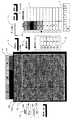
図1は,相手および味方選手の第1偵察画面のサーブレシーブデータ入力画面を示したものである。図中に表示した1は「相手チーム一覧」の画像部分である。同図中の2は「スターティングメンバー入力用のオプションボタン」画像である。「相手チーム名入力」画像11に、相手チーム名を入力し、相手選手の識別名称(図1では背番号で識別)を「相手チーム一覧」1にキーボードで入力する。次いで「スターティングメンバー入力用のオプションボタン」2をゲームに出場する相手選手6人について、RB,RF,CF,LF,LB,CBのポジション順に選択し,「スタメン」ボタン画像3を実行する。そうすると「スターティングメンバー表示画像」4に出場選手名(図1では識別番号)が選手識別色分けのカラーで表示される。また、「相手チーム一覧」1にもスターティングメンバーの色分けが表示される。 Fig. 1 shows the receive data input screen of the first reconnaissance screen of the opponent and teammates.
小学生バレーボールはローテーションなしのフリーポジションであるから,最初にコートのR B,RF,CF,LF,LB,CBのポジションに居る相手チーム選手の配置を確認して前記のポジション順による入力を行えば、相手チームの選手交代がない限り、その後の相手選手のポジション変更入力は不要である。選手交代が生じた場合は、「オプションボタン」2で交代する選手を指定し、さらに「選手交代」ボタン画像6をクリックすれば、「スターティングメンバー表示画面」4の選手識別名が変更される。さらに、ゲームに出場する味方選手6人をサーブ順に「味方チーム一覧」5に入力する。以上の前記した選手登録の入力作業は,サーブレシーブのデータ入力を開始する前に完了させておく。 Since elementary school volleyball is a free position without rotation, first confirm the placement of the opponent team players in the RB, RF, CF, LF, LB, and CB positions on the court and input in the above order of positions. As long as there is no player change of the opponent team, it is not necessary to input the position change of the opponent player thereafter. When a player change occurs, a player to be changed is designated with the “option button” 2 and the player identification name on the “starting member display screen” 4 is changed by clicking the “player change”
図2は試合中に行うサーブレシーブデータの入力状況の例である。味方チームのサーブ開始前に、先ず味方チームのサーバを「味方チーム一覧」5で選択する。次いで「全体/個別選択」ボタン画像7により、相手チームの特定選手について入力するか、相手チーム全体について入力するかを選択する。すなわち「全体/個別選択」ボタン画像7は、「全体」か、相手チームの選手識別名(図2では選手識別番号を使用)を表示したボタン画像で構成され、相手チームの特定選手の識別名称(図2では番号で表示)を選択し、さらに当該選手の実際のコート上での位置を観測し、「コート画像」8内の相当位置をクリックすれば当該選択の位置がコート画像8上のクリックした位置に表示される。「コート画像」8はコートの片面を矩形画像で表し、さらに位置入力を容易にするため、3X3の矩形エリアに区分してある。当該全体矩形に対する相対位置を、実際のバレーコート上の位置に対応させる。 FIG. 2 shows an example of the input status of the receive data that is performed during the match. Before the team of the teammates starts serving, the server of the teammates is first selected in the “team team list” 5. Next, the “all / individual selection”
図3において、「全体/個別選択ボタン」7で「全体」をクリックした後、相手チーム選手の位置の観察結果にもとずいて、後衛3人、続いて前衛3人の相当する「コート画像」8上の位置を順次クリックすると、当該後衛選手3人のコート上位置を塗りつぶしたポイント9aで、前衛選手3人のそれを観察した当該選手の位置を色抜きポイント9bで表示される。前記した入力により、味方サーバに対する相手チームのサーブレシーブ隊形をコンピュータに入力させることができる。さらに図3において、「隊形分析」ボタン画像9は、味方サーバに関連付けて相手チーム選手の守備隊形を選択的にコンピュータに入力し、保存するためのものである。すなわち、味方サーバ名を選択し、コート画像8上で相手チーム選手の位置に相当する点をクリックし、次いで「隊形分析」ボタン画像9をクリックすれば、コンピュータは、当該コート画像8上でクリックした位置を、相手チームの後衛選手から前衛選手の順序で個々に対応させて認識する。コンピュータは、そのように認識した相手チーム選手の位置データを、選択した味方サーバに対する相手チームの守備隊形のデータとして保存し、図3において9a、9bとして表示したポイントを、コート画像8上の前記クリック位置に表示する。このような「隊形分析」ボタンに関連する機能は、偵察者が観察の結果にもとずいて、相手チームの代表的な守備隊形を選択し、コンピュータに保存する目的に利用できる。 In FIG. 3, after clicking “all” with the “total / individual selection button” 7, based on the observation result of the position of the opponent team player, the corresponding “court image” of three rear guards and then three front guards When the position on 8 is sequentially clicked, the position of the player who observed the positions of the three avant-garde players is displayed as a
味方選手によるサーブが行われた結果を観察し、レシーブした相手選手を「相手チームスターティングメンバー」画像4の中からクリックして選択し、レシーブした位置を「コート画像」8上でクリックする。さらに、レシーブの評価値を入力する画面10から、「コンビ」、「2段、チャンス」あるいは「エース」の何れかをクリックして選択入力する。 The result of serving by the teammate player is observed, the received opponent player is clicked and selected from the “partner team starting member”
上記データ入力結果を分析して表示した例を図2に示す。図2では蓄積、保存データを処理して、「相手チーム一覧」画像1の成功率リストに相手チームの個々の選手について(図2の画面では1と5の識別番号の選手)の成功率と打数を表示している。 An example of analyzing and displaying the data input result is shown in FIG. In FIG. 2, the accumulated and saved data are processed, and the success rate list for each player of the opponent team (players with
ゲームの途中で選手交代が生じたら,その時点で出場選手そして交代選手の順番で選手名簿の「オプションボタン」2を選択し,「選手交代」ボタン6を実行すると,「スターティングメンバ表示画像」4の選手識別名が変更され,その後継続して入力を行う。 If a player change occurs in the middle of the game, select “Option Button” 2 in the player list in the order of the participating player and the substitute player at that time, and execute “Change Player”
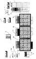
図4は第2偵察端末の表示部における、攻撃データ入力画面を示す。図4中に表示した「相手チーム一覧」1、「スターティングメンバー入力用のオプションボタン」2、「スタメンボタン」3、「スターティングメンバ表示」画像4、「チーム名入力」画像11、及び「選手交代ボタン」6は第1偵察端末の表示画面と同様な機能を有する。「アタックレシーブ評価入力」画像12は「決定」12a、「ラリー」12b、「シャット」12c及び「ミス」12dの4段階表示画像ボタンから成る。 FIG. 4 shows an attack data input screen on the display unit of the second reconnaissance terminal. In FIG. 4, the “partner team list” 1, “starting member input option button” 2, “starting member button” 3, “starting member display”
図4に示すように、第1偵察端末の画像表示に記載した、「コート画像」8と同様な矩形画像と、該画像8の輪郭を成す矩形の水平方向辺に平行に、3つの矩形を上下3段に並べて配置した「攻撃方向画像」13を表示する。当該3個の矩形で構成する「攻撃方向画像」13のうち、最下段の矩形13aはクイック攻撃に相当するアタックトス高さを表示し、2番目の矩形13bは、平行トスに相当するアタックパスの高さを、3段目の矩形13cは、2段攻撃のアタックトスの高さに対応する。矩形13の横方向幅は、コートの幅に相当し、相手チームのアタックに対して行った味方チームのサーブレシーブ位置、又はアタック球の着床位置についてのコート横方成分を、コート幅に対する相対位置で表す。例えば、アタックトスが「クイック攻撃」相当トス高さで行われた場合には、矩形13aのエリア内において、該アタックをレシーブした味方選手のコート横方向位置に相当する該矩形の幅(又は横)方向位置でクリックすれば、攻撃球のトス高さとレシーブ横方向位置の入力が可能である。 As shown in FIG. 4, a rectangular image similar to the “coat image” 8 described in the image display of the first reconnaissance terminal and three rectangles parallel to the horizontal side of the rectangle that forms the outline of the
選手登録の入力作業は,ゲームの開始前に完了させておく。相手チームの選手及び同スターティングメンバーの入力は第1偵察端末について上記に記載したと同様の手順で行う。相手チームの攻撃が行われる度に、「スターティングメンバ表示」画像4でアタックした相手チームの選手を指定し、「攻撃方向画像」13から前記攻撃時のトス高さに相当する矩形を選択し、そのエリア内のレシーブ横方向位置に相当する点をクリックする。さらに、「アタックレシーブ評価入力」画像12において当該攻撃の評価値を13aないし13dから選択する。 The player registration input work must be completed before the game starts. The player and the starting member of the opponent team are input in the same procedure as described above for the first reconnaissance terminal. Each time the opponent team is attacked, the player of the opponent team who attacked is designated in the “starting member display”
図5は上記第2偵察端末からの入力結果を利用して、攻撃分析データ表示したものである。上記の相手チームアタッカーがアタックした「コート画像」8上の位置と、該アタック球のレシーブあるいは着床位置として入力時にクリックした「攻撃方向画像」13上位置に相当する2点を接続して、該攻撃の方向を示す線分14を表示する。 FIG. 5 shows attack analysis data displayed using the input result from the second reconnaissance terminal. Two points corresponding to the position on the “court image” 8 attacked by the opponent team attacker and the position on the “attack direction image” 13 clicked at the time of input as the receive or landing position of the attack ball, are connected, A
図6は第3偵察端末の表示部における、攻撃に対する守備データ入力画面を示す。図6中に表示した「相手チーム一覧」1、「スターティングメンバー入力用のオプションボタン」2、「スタメンボタン」3、「チーム名入力」画像11、及び「選手交代ボタン」6は第1偵察端末の表示画面と同様な機能を有する。「守備評価入力」画像15は「良レシーブ」15a、「ラリー」15b、及び「攻撃決定」15cの3段階表示画像ボタンから成る。「スターティングメンバ表示」画像4も第1偵察端末の当該画像と同様な機能である。 FIG. 6 shows a defensive data input screen for an attack on the display unit of the third reconnaissance terminal. In FIG. 6, “list of opponent teams” 1, “option button for starting member input” 2, “stamen button” 3, “team name input”
第3偵察端末の入力画面においては、「左攻撃コート画像」8a、「中央攻撃コート画像」8b、及び「右攻撃コート画像」8cと3画像が表示される。味方の攻撃がコートの左サイドから行われた場合は「左攻撃コート画像」8a、中央からの場合は「中央攻撃コート画像」8b、右側の場合は「右攻撃コート画像」8cをそれぞれ使用して、当該味方攻撃をレシーブした相手チーム選手の位置、あるいは着床したボール位置を入力する。 On the input screen of the third reconnaissance terminal, “left attack court image” 8a, “center attack court image” 8b, and “right attack court image” 8c are displayed. When a teammate's attack is made from the left side of the court, the “left attack court image” 8a is used, “center attack court image” 8b is used from the center, and “right attack court image” 8c is used from the right side. Then, the position of the opponent team player who received the friendly attack or the position of the ball that landed is input.
図6において、味方アタッカー名を入力するために「味方アタッカー画像」16を表示する。この画像中の選手名入力欄に味方スタッカー3名を入力する。ローテーションなしルールをベースとした偵察システムであるから、味方アタッカーは3名に限定されており、ローテーションありルール対応の偵察システムにおけるようにアタッカーをローテーションに対応して変更する入力画像は不要である。従って入力画像の構成は簡単化され、入力操作の負担も軽減する。 In FIG. 6, a “friend attacker image” 16 is displayed in order to input a friend name. Enter three teammate stackers in the player name input field in this image. Since it is a reconnaissance system based on the rule without rotation, the number of friendly attackers is limited to three, and an input image for changing the attacker according to the rotation is not required as in the reconnaissance system corresponding to the rule with rotation. Therefore, the configuration of the input image is simplified and the burden of the input operation is reduced.
相手チーム選手登録、相手スターティングメンバーの入力は第1偵察端末について説明したのと同様に行なった後、試合中の味方アタッカーの攻撃の都度、その状況を入力する。すなわち、味方アタッカー名を「味方アタッカー画像」16から選択し、該攻撃球をレシーブした相手チームの選手を「スターティングメンバ表示」画像4で選択する。前記味方アタッカーによる攻撃がコートの左、中央又は右側のいずれで行われたかに応じて、8aないし8cの「攻撃コート画像」を選択し、当該画像上において前記相手選手のレシーブ位置(又は着床位置)に相当する前記選択したコート画像上でクリックする。次いで「守備評価入力」画像15により、攻撃結果を15aないし15cの選択により入力する。 The opponent team player registration and the opponent starting member are input in the same manner as described for the first reconnaissance terminal, and then the status is entered every time a friendly attacker attacks during the match. That is, the name of the ally attacker is selected from the “friend attacker image” 16, and the player of the opponent team that received the attack ball is selected in the “starting member display”
図7は、前記第3偵察端末により入力した守備データを利用した分析画面の表示例である。「味方アタッカー画像」16より選手を選択すれば、当該選手の攻撃に対して相手チームが取った守備隊形が、相手チーム選手の位置を示す「コート画像」上のポイントで表示される。図7ではレフト攻撃の選手に対する結果であるから、「左攻撃コート画像」8aにポイントが表示される。また相手チーム守備隊形を表示するポイントは後衛選手が白抜きポイントで、前衛選手が塗りつぶしのポイントで表示されている。さらに図7において、「隊形分析」ボタン画像9は、味方アタッカに関連付けて相手チーム選手のアタック守備隊形を選択的にコンピュータに入力し、保存するためのものである。すなわち、味方アタッカ名を選択し、コート画像8上で相手チーム選手の位置に相当する点をクリックし、次いで「隊形分析」ボタン画像9をクリックすれば、コンピュータは、当該コート画像8上でクリックした位置を、相手チームの後衛選手から前衛選手の順序で個々に対応させて認識する。コンピュータは、そのように認識した相手チーム選手の位置データを、選択した味方アタッカに対する相手チームの守備隊形のデータとして保存し、図7において9a、9bとして表示したポイントを、コート画像8上の前記クリック位置に表示する。このような「隊形分析」ボタンに関連する機能は、偵察者が観察の結果にもとずいて、相手チームの代表的な守備隊形を選択し、コンピュータに保存する目的に利用できる。
FIG. 7 is a display example of an analysis screen using defensive data input by the third reconnaissance terminal. If a player is selected from the “friend attacker image” 16, the garrison form taken by the opponent team against the attack of the player is displayed as a point on the “court image” indicating the position of the opponent team player. In FIG. 7, since it is the result for the player of the left attack, points are displayed in the “left attack court image” 8a. In addition, the points for displaying the opponent team garrison form are the white points for the rear guard and the solid points for the front guard. Further, in FIG. 7, a “form formation analysis”
ローテーションなしルールのバレーボール競技用の偵察システムとして必要な機能に限定して簡素な入力画面構成を可能とした。これにより、安価で、入力の容易なシステムを提供し、経費や人的に制約の多い小学生や初心者チームでも広く、簡単に使用できる偵察システムを実現し、スポーツ教育の向上、発展にも資する。 A simple input screen configuration is possible only for functions required as a reconnaissance system for volleyball competition with no rotation rules. This provides an inexpensive and easy-to-input system, and realizes a reconnaissance system that can be used easily and easily by elementary school students and beginner teams with limited costs and human resources, contributing to the improvement and development of sports education.
1 「相手チーム一覧」入力の画像部分
2 「スターティングメンバー入力用のオプションボタン」の画像部分
3 「スタメン」入力の画像部分
4 「相手チームスターティングメンバー」の画像部分
5 「味方チーム一覧」入力の画像部分
6 「選手交代」ボタン画像
7 「全体/個別選択ボタン」画像
8 「コート画像」
8a 「左攻撃コート画像」
8b 「中央攻撃コート画像」
8c 「右攻撃コート画像」
9 「隊形分析」ボタン画像
9a 後衛選手位置のポイント画像
9b 前衛選手位置のポイント画像
10 「レシーブの評価値」を入力する画像
11 チーム名入力用画像
12 「アタックレシーブ(又は攻撃レシーブ)評価値」の入力用画像
12a 「決定」選択用画像
12b 「ラリー」選択用画像
12c 「シャット」選択用画像
12d 「ミス」選択用画像
13 「攻撃方向」入力用画像
14 攻撃方向を示す線の画像
15 「守備評価値」の入力用画像
15a 「良レシーブ」選択用画像
15b 「ラリー」選択用画像
15c 「攻撃決定」選択用画像
16 「味方アタッカ」入力用画像
17 表示部
18 キーボード
19 ポインティングデバイス
20 制御部
21 メモリ1 "Partner team list"
4 “Partner team starting member”
8a "Left attack court image"
8b "Central attack court image"
8c “Right attack court image”
9 “Form formation analysis”
14 Image of line indicating
Claims (4)
Translated fromJapanese(1)前記コンピュータ端末の第1のものは、表示部に、サーブレシーブ状況のデータ入力用のグラフィック画面を表示するよう構成され、同グラフィック画面には、バレーコートの模擬画像、相手チームの選手の登録と、相手チームのスターティングメンバーをポジションに対応させて選定する入力画像、味方チームのメンバーをサーブプレー順に指定するための入力画像、及びサーブプレーの評価値の入力画像の表示を含み、
(イ)試合開始前に、前記相手チーム選手登録および相手チームスターティングメンバー選定のための前記入力画象からの入力と、前記サーブプレー順を指定する入力画面を使用して味方チームのメンバーをサーブプレーの順番で指定する入力を行うことにより、該入力した相手、味方選手のデータをメモリに保存し、
(ロ)味方選手のサーブ球をレシーブした相手チームの選手を選択し、当該選択した選手がレシーブしたコート上の位置に相当する、前記コート模擬画像上の対応する位置をポインティングデバイスによりクリックして入力し、さらに当該サーブレシーブプレーの評価値を入力すると、サーブした味方選手、当該サーブ球をレシーブした相手チーム選手とレシーブした位置、及び該レシーブプレーを評価する値を含むデータを取得し、保存し、サーブレシーブした相手選手位置を前記コート模擬画像上にポインタで表示する。
(2)前記コンピュータ端末の第2のものは、表示部において、攻撃状況のデータ入力用のグラフィック画面を表示するよう構成され、同グラフィック画面には、バレーコートの模擬画像、相手チームの選手の登録と、相手チームのスターティングメンバーをポジションに対応させて選定する入力画像、攻撃プレーの評価値の入力画像、及び攻撃のアタックトスの高さと、味方コートにおける当該攻撃球の着床位置又は味方チーム選手によるレシーブ位置を入力する複数の矩形から構成される画像を含み、
(イ)試合開始前に、前記相手チーム選手登録およびスターティングメンバー入力画像を使用して相手チーム選手を登録選定する入力行うことにより、該入力した相手選手のデータをメモリに保存し、
(ロ)相手チームの選手がアタックを行う毎に、当該相手チームの選手を選択し、当該選手がアタックした位置をコート模擬画像上においてポインティングデバイスでクリック入力し、
(ハ)該攻撃のアタックトスの高さは、コート模擬画像と平行に積み重ねて表示した、前記複数個の矩形の画像のエリアの1を選択することにより、さらに、前記味方コートにおける攻撃球の着床又は攻撃レシーブを行った味方選手のコート上位置の横方向成分を、前記選択した矩形エリアの横方向位置を指定してクリックすることにより入力し、さらに攻撃プレー評価値を選択入力すると、前記入力されたデータは相手チームアタッカー名と対応するアタックトス高さ、レシーブ又は着床位置及び攻撃評価値として蓄積、保存され、
(ニ)前記保存された相手チームの攻撃位置を1の端点とし、攻撃球の着床あるいはレシーブ位置、及びアタックトス高さを示すポイントを他の端点とした、コート模擬画像上の線分の表示を可能とする。
(3)前記コンピュータ端末の第3のものは、表示部において、アタックに対する、相手チームの守備隊形状況のデータ入力用のグラフィック画面を表示するよう構成され、同グラフィック画面には、アタックが行われた位置が、コート右側、中央又は左側のいずれであるかに対応して選択し、相手守備隊形データを入力する3個のバレーコート模擬画像、相手チームの選手の登録と、相手チームのスターティングメンバーをポジションに対応させて選定する入力画像、味方チームのアタックを行うメンバーを指定するための入力画像、及びアタックに対する守備プレーの評価値の入力画像を含み、
(イ)試合開始前に、前記スターティングメンバー入力画像により相手チームの選手と相手チームスターティングメンバーの入力、及び味方チームのアタックメンバー入力画像により味方アタックメンバーの入力を行うことにより、相手スターティングメンバーと味方アタックメンバーのデータを保存し、
(ロ)味方選手がアタックを行う毎に、アタックを行った味方選手の選択入力、そのアタックの行われた位置がコート右側か、中央か、あるいは左側かに応じて、前記3個のコート模擬画像から対応するものを選択し、味方アタックに対応して守備レシーブをした相手選手を選択し、前記選択したコート模擬画像上において、当該守備レシーブが行われた位置をクリックして入力し、さらに当該守備レシーブの評価値を入力すれば、前記入力されたデータは味方チームのアタックした選手名との対応で、相手チームのアタック守備隊形のデータとして取得、保存され、
(ハ)前記のように保存されたデータにより、コート模擬画面上に、アタックレシーブを行った相手チーム選手の位置がポインタで重畳表示される、A volleyball reconnaissance system that enables the input of data observed by scouts, stores and saves the input data, and displays the analysis results of the data regarding the playing state of volleyball competitions according to the rule without rotation. A reconnaissance system comprising a plurality of computer terminals provided with a device, wherein the graphic interface and the input / output data processing in the display unit of the computer terminal are configured as follows.
(1) The first computer terminal is configured to display on the display unit a graphic screen for data input of a serve-being situation. The graphic screen includes a simulated image of a volleyball court and a player of the opponent team. Registration, the input image that selects the starting member of the opponent team corresponding to the position, the input image for designating the members of the ally team in the order of serve play, and the display of the input image of the evaluation value of the serve play,
(B) Before starting the match, use the input screen to register the opponent team player and select the opponent team starting member, and use the input screen to specify the order of serve play. By performing the input specified in the order of serve play, the input opponent and teammate data is saved in the memory,
(B) Select a player of the opponent team that received the serve ball of the teammate player, and click the corresponding position on the court simulated image corresponding to the position on the court that the selected player received with the pointing device. If you input the evaluation value of the serve-behind play, the data including the saved teammate player, the opponent team player who received the serve ball and the received position, and the value to evaluate the receive-play are acquired and saved. Then, the position of the opponent player serving as a serve is displayed on the court simulated image with a pointer.
(2) The second computer terminal is configured to display on the display unit a graphic screen for data input of the attack status, and on the graphic screen, the simulated image of the volleyball court, the player of the opponent team Registration, input image to select the starting member of the opponent team corresponding to the position, input image of evaluation value of attack play, attack attack toss height, landing position or ally of the attack ball on the ally court It contains an image composed of multiple rectangles that enter the receive position by the team player,
(B) Before starting the match, by performing input to register and select the opponent team player using the opponent team player registration and starting member input image, the input opponent player data is stored in the memory,
(B) Each time a player of the opponent team attacks, the player of the opponent team is selected, and the position where the player has attacked is click-inputted on the court simulated image with a pointing device,
(C) The attack toss height of the attack is selected by selecting one of the plurality of rectangular image areas stacked and displayed in parallel with the simulated coat image. Enter the horizontal component of the on-court position of the teammate who made the landing or attack receive by specifying the horizontal position of the selected rectangular area and clicking, and further select and input the attack play evaluation value, The input data is stored and stored as the attack toss height, receive or landing position and attack evaluation value corresponding to the opponent team attacker name,
(D) A line segment on the court simulation image in which the attack position of the saved opponent team is one end point and the attack ball landing or receive position and the point indicating the attack toss height are other end points. Enable display.
(3) The third computer terminal is configured to display on the display unit a graphic screen for data input of the opponent team's garrison status against the attack, and the graphic screen is attacked. 3 positions are selected according to whether the position is on the right side, center, or left side of the court, and the opponent's team players are registered. Including an input image for selecting members according to positions, an input image for designating members to attack teammates, and an input image of an evaluation value of defensive play against the attack,
(A) Before starting the match, by inputting the opponent team's player and opponent team starting member with the above starting member input image, and with the team member's attack member input image, the opponent starting member is input. Save data of members and friendly attack members,
(B) Each time a teammate performs an attack, the selection of the teammate who performed the attack, and the three court simulations, depending on whether the attack was made on the right side, center, or left side Select the corresponding one from the images, select the opponent player who received the defensive reception in response to the team attack, click on the position where the defensive reception was performed on the selected court simulated image, and input it. If the evaluation value of the defensive receive is input, the input data is acquired and saved as the attack team formation data of the opposing team in correspondence with the name of the player who attacked the team.
(C) Based on the data stored as described above, the position of the opponent team player who performed the attack receive is superimposed on the court simulation screen with a pointer.
(1)前記サーブレシーブ状況データ入力用のグラフィック画面において、サーブを行う味方選手を選択する入力、相手チーム選手個々の守備位置をあらかじめ設定された順序に従ってコート模擬画像上においてポインティングデバイスによるクリックを行って指定する入力、及び前記「隊形分析」ボタン画像を指定する入力操作を行うことにより、
(2)前記のようにクリックして入力したコート模擬画像上の位置を、前記のように選択した味方選手のサーブに対応する相手チームの守備隊形のデータとして保存し、該相手チームの守備隊形を、相手選手個々の位置を示すポインターによりコート模擬画像に重畳して表示する機能を含むことを特徴とする、請求項1に記載の偵察システム。The graphic screen for inputting the serve situation data in the first terminal display unit according to claim 1 includes a “form analysis” button image,
(1) On the graphic screen for inputting the serve situation data, an input for selecting a teammate player to serve, and a click on the simulated image of the opponent team player on the court simulated image according to a preset order. By performing an input operation for designating and specifying the “form formation analysis” button image,
(2) The position on the court simulated image clicked and input as described above is stored as the data of the opponent team's garrison type corresponding to the serve of the teammate player selected as described above, and the opponent team's garrison type 2. The reconnaissance system according to claim 1, further comprising: a function of displaying an image superimposed on a court simulated image with a pointer indicating the position of each opponent player.
(1)前記アタックに対する、相手チームの守備隊形状況のデータ入力用のグラフィック画面において、アタックを行う味方選手を選択する入力、相手チーム選手個々の守備位置をあらかじめ設定された順序に従ってコート模擬画像上においてポインティングデバイスによるクリックを行って指定する入力、及び前記「隊形分析」ボタン画像を指定する入力操作を行うことにより、
(2)前記のようにクリックして入力したコート模擬画像上の位置を、前記のように選択した味方選手のアタックに対応する相手チームの守備隊形のデータとして保存し、該相手チームの守備隊形を、相手選手個々の位置を示すポインターによりコート模擬画像に重畳して表示する機能を含むことを特徴とする、請求項1に記載の偵察システム。In the third terminal display section according to claim 1, the graphic screen for data input of the defensive team status of the opponent team for the attack includes a “form formation analysis” button image,
(1) On the graphic screen for data input of the opponent team's defensive team status for the attack, on the court simulated image according to the order in which the opponent team player's individual defensive position is set in advance By performing an input operation to specify by performing a click with a pointing device and specifying the “form formation analysis” button image,
(2) The position on the court simulated image input by clicking as described above is saved as the data of the opponent team's garrison shape corresponding to the attack of the teammate player selected as described above, and the opponent team's garrison shape 2. The reconnaissance system according to claim 1, further comprising: a function of displaying an image superimposed on a court simulated image with a pointer indicating the position of each opponent player.
Priority Applications (1)
| Application Number | Priority Date | Filing Date | Title |
|---|---|---|---|
| JP2006082181AJP4759742B2 (en) | 2006-03-24 | 2006-03-24 | Play data collection, analysis system, data collection and analysis program for volleyball competition |
Applications Claiming Priority (1)
| Application Number | Priority Date | Filing Date | Title |
|---|---|---|---|
| JP2006082181AJP4759742B2 (en) | 2006-03-24 | 2006-03-24 | Play data collection, analysis system, data collection and analysis program for volleyball competition |
Publications (2)
| Publication Number | Publication Date |
|---|---|
| JP2007252697A JP2007252697A (en) | 2007-10-04 |
| JP4759742B2true JP4759742B2 (en) | 2011-08-31 |
Family
ID=38627524
Family Applications (1)
| Application Number | Title | Priority Date | Filing Date |
|---|---|---|---|
| JP2006082181AActiveJP4759742B2 (en) | 2006-03-24 | 2006-03-24 | Play data collection, analysis system, data collection and analysis program for volleyball competition |
Country Status (1)
| Country | Link |
|---|---|
| JP (1) | JP4759742B2 (en) |
Families Citing this family (6)
| Publication number | Priority date | Publication date | Assignee | Title |
|---|---|---|---|---|
| CN102380185B (en)* | 2011-10-18 | 2013-05-15 | 中国科学院合肥物质科学研究院 | A control system for mountain training based on intelligent treadmill |
| JP7296546B2 (en)* | 2018-10-04 | 2023-06-23 | パナソニックIpマネジメント株式会社 | Play analysis device and play analysis method |
| JP7300668B2 (en)* | 2019-05-10 | 2023-06-30 | パナソニックIpマネジメント株式会社 | Play analysis device and play analysis method |
| JP7345108B2 (en)* | 2019-06-20 | 2023-09-15 | パナソニックIpマネジメント株式会社 | Play analysis device, play analysis method, and computer program |
| CN112528785B (en)* | 2020-11-30 | 2025-01-24 | 联想(北京)有限公司 | Information processing method and device |
| JP7144778B1 (en) | 2022-08-02 | 2022-09-30 | シンメディクト株式会社 | Competition Management Program, Competition Management Device |
Family Cites Families (5)
| Publication number | Priority date | Publication date | Assignee | Title |
|---|---|---|---|---|
| JPS6214874U (en)* | 1985-07-10 | 1987-01-29 | ||
| JP2001273500A (en)* | 2000-03-23 | 2001-10-05 | Hitachi Ltd | Moving object measurement device, ball game analysis system, and data service system |
| JP2004046647A (en)* | 2002-07-12 | 2004-02-12 | Univ Waseda | Method and device for tracking moving object based on dynamic image data |
| JP3760237B2 (en)* | 2003-05-30 | 2006-03-29 | 国立大学法人広島大学 | Scouting system, method and program |
| JP3975276B2 (en)* | 2004-09-30 | 2007-09-12 | 国立大学法人広島大学 | Reconnaissance system, reconnaissance program, computer-readable recording medium |
- 2006
- 2006-03-24JPJP2006082181Apatent/JP4759742B2/enactiveActive
Also Published As
| Publication number | Publication date |
|---|---|
| JP2007252697A (en) | 2007-10-04 |
Similar Documents
| Publication | Publication Date | Title |
|---|---|---|
| KR100708494B1 (en) | Use in computer games of voronoi diagrams for partitioning a gamespace for analysis | |
| US8016664B2 (en) | Systems and methods for simulating a particular user in an interactive computer system | |
| EP2234681B1 (en) | Athletic training system | |
| US10471357B2 (en) | Systems and methods for simulating a particular user in an interactive computer system | |
| JP4759742B2 (en) | Play data collection, analysis system, data collection and analysis program for volleyball competition | |
| CN110727826A (en) | A visual analysis method of table tennis tactics mining | |
| CN113610010B (en) | Visual analysis system of badminton tactics based on immersive formula | |
| Flores-Rodríguez et al. | Variability in performance indicators of the Netherlands women’s national handball team at the 2019 World Championship | |
| JP3975276B2 (en) | Reconnaissance system, reconnaissance program, computer-readable recording medium | |
| Külah et al. | Quantifying the value of sprints in elite football using spatial cohesive networks | |
| JP7268738B2 (en) | DISPLAY METHOD, DISPLAY PROGRAM AND INFORMATION PROCESSING DEVICE | |
| US11776266B1 (en) | Assessing player performance in a sport using a graphical user interface | |
| JP6302524B1 (en) | Program creation system, game execution system and program | |
| Bouzarth et al. | Storytelling with sports analytics | |
| Andrianova et al. | Digital scouting technologies in game sports | |
| Varga et al. | Esports player analytics | |
| Plener | Opponent Analysis in Football | |
| Alonso-Pérez-Chao et al. | Identifying winning strategies: analysis of play-types in professional European basketball leagues | |
| JP3760237B2 (en) | Scouting system, method and program | |
| Sobhana | ARTIFICIAL INTELLIGENCE AND SPORTS ANALYTICS | |
| Tilp | Modelling in the analysis of tactical behavior in team handball | |
| Chang et al. | An animation assisted training system for the baseball cover, relay and cutoff play | |
| Szwarc et al. | Proposal of an observation sheet for basketball players’ performance assessment | |
| Verlin et al. | PoloTrac: A Water Polo Tracking and Advanced Statistics Application. | |
| CN113625876A (en) | Immersion-based badminton tactics analysis method |
Legal Events
| Date | Code | Title | Description |
|---|---|---|---|
| A621 | Written request for application examination | Free format text:JAPANESE INTERMEDIATE CODE: A621 Effective date:20090206 | |
| A977 | Report on retrieval | Free format text:JAPANESE INTERMEDIATE CODE: A971007 Effective date:20110421 | |
| A01 | Written decision to grant a patent or to grant a registration (utility model) | Free format text:JAPANESE INTERMEDIATE CODE: A01 Effective date:20110510 | |
| R150 | Certificate of patent or registration of utility model | Free format text:JAPANESE INTERMEDIATE CODE: R150 |