JP4759168B2 - Liquid heater and analyzer equipped with the same - Google Patents
Liquid heater and analyzer equipped with the sameDownload PDFInfo
- Publication number
- JP4759168B2 JP4759168B2JP2001172964AJP2001172964AJP4759168B2JP 4759168 B2JP4759168 B2JP 4759168B2JP 2001172964 AJP2001172964 AJP 2001172964AJP 2001172964 AJP2001172964 AJP 2001172964AJP 4759168 B2JP4759168 B2JP 4759168B2
- Authority
- JP
- Japan
- Prior art keywords
- liquid
- substrate
- sealing plate
- opening
- internal space
- Prior art date
- Legal status (The legal status is an assumption and is not a legal conclusion. Google has not performed a legal analysis and makes no representation as to the accuracy of the status listed.)
- Expired - Fee Related
Links
- 239000007788liquidSubstances0.000titleclaimsdescription74
- 239000000758substrateSubstances0.000claimsdescription37
- 238000007789sealingMethods0.000claimsdescription26
- 210000002445nippleAnatomy0.000claimsdescription14
- 238000010438heat treatmentMethods0.000claimsdescription12
- 239000000126substanceSubstances0.000claimsdescription11
- 239000000463materialSubstances0.000claimsdescription3
- 238000012856packingMethods0.000claimsdescription3
- 230000000149penetrating effectEffects0.000claimsdescription3
- 238000007599dischargingMethods0.000claimsdescription2
- 230000035515penetrationEffects0.000claimsdescription2
- 239000003153chemical reaction reagentSubstances0.000description14
- 239000011347resinSubstances0.000description14
- 229920005989resinPolymers0.000description14
- 238000004140cleaningMethods0.000description13
- 239000000523sampleSubstances0.000description8
- 239000012470diluted sampleSubstances0.000description7
- 210000004369bloodAnatomy0.000description4
- 239000008280bloodSubstances0.000description4
- 229910052751metalInorganic materials0.000description4
- 239000002184metalSubstances0.000description4
- 238000005070samplingMethods0.000description4
- 238000003860storageMethods0.000description4
- 210000004027cellAnatomy0.000description3
- 238000010586diagramMethods0.000description3
- 238000000034methodMethods0.000description3
- 239000004697PolyetherimideSubstances0.000description2
- 229910052782aluminiumInorganic materials0.000description2
- XAGFODPZIPBFFR-UHFFFAOYSA-NaluminiumChemical compound[Al]XAGFODPZIPBFFR-UHFFFAOYSA-N0.000description2
- 239000000919ceramicSubstances0.000description2
- 238000007865dilutingMethods0.000description2
- 239000003085diluting agentSubstances0.000description2
- 238000009413insulationMethods0.000description2
- 238000004519manufacturing processMethods0.000description2
- 150000002739metalsChemical class0.000description2
- 239000002245particleSubstances0.000description2
- 229920001601polyetherimidePolymers0.000description2
- 239000000243solutionSubstances0.000description2
- 229910001220stainless steelInorganic materials0.000description2
- 239000010935stainless steelSubstances0.000description2
- RYGMFSIKBFXOCR-UHFFFAOYSA-NCopperChemical compound[Cu]RYGMFSIKBFXOCR-UHFFFAOYSA-N0.000description1
- 229930182556PolyacetalNatural products0.000description1
- -1PolyethylenePolymers0.000description1
- 239000004698PolyethyleneSubstances0.000description1
- 206010037660PyrexiaDiseases0.000description1
- XUIMIQQOPSSXEZ-UHFFFAOYSA-NSiliconChemical compound[Si]XUIMIQQOPSSXEZ-UHFFFAOYSA-N0.000description1
- BQCADISMDOOEFD-UHFFFAOYSA-NSilverChemical compound[Ag]BQCADISMDOOEFD-UHFFFAOYSA-N0.000description1
- 239000000853adhesiveSubstances0.000description1
- 230000001070adhesive effectEffects0.000description1
- 229910052802copperInorganic materials0.000description1
- 239000010949copperSubstances0.000description1
- 230000003247decreasing effectEffects0.000description1
- 239000012895dilutionSubstances0.000description1
- 238000010790dilutionMethods0.000description1
- 230000000694effectsEffects0.000description1
- 238000009429electrical wiringMethods0.000description1
- 210000003743erythrocyteAnatomy0.000description1
- 239000006260foamSubstances0.000description1
- 239000003219hemolytic agentSubstances0.000description1
- 238000001746injection mouldingMethods0.000description1
- 239000011810insulating materialSubstances0.000description1
- 230000002934lysing effectEffects0.000description1
- 238000000465mouldingMethods0.000description1
- 229920001643poly(ether ketone)Polymers0.000description1
- 229920000573polyethylenePolymers0.000description1
- 229920006324polyoxymethylenePolymers0.000description1
- 229910052710siliconInorganic materials0.000description1
- 239000010703siliconSubstances0.000description1
- 229920002379silicone rubberPolymers0.000description1
- 229910052709silverInorganic materials0.000description1
- 239000004332silverSubstances0.000description1
Images


Classifications
- F—MECHANICAL ENGINEERING; LIGHTING; HEATING; WEAPONS; BLASTING
- F25—REFRIGERATION OR COOLING; COMBINED HEATING AND REFRIGERATION SYSTEMS; HEAT PUMP SYSTEMS; MANUFACTURE OR STORAGE OF ICE; LIQUEFACTION SOLIDIFICATION OF GASES
- F25B—REFRIGERATION MACHINES, PLANTS OR SYSTEMS; COMBINED HEATING AND REFRIGERATION SYSTEMS; HEAT PUMP SYSTEMS
- F25B21/00—Machines, plants or systems, using electric or magnetic effects
- F25B21/02—Machines, plants or systems, using electric or magnetic effects using Peltier effect; using Nernst-Ettinghausen effect
- F25B21/04—Machines, plants or systems, using electric or magnetic effects using Peltier effect; using Nernst-Ettinghausen effect reversible
- B—PERFORMING OPERATIONS; TRANSPORTING
- B01—PHYSICAL OR CHEMICAL PROCESSES OR APPARATUS IN GENERAL
- B01L—CHEMICAL OR PHYSICAL LABORATORY APPARATUS FOR GENERAL USE
- B01L7/00—Heating or cooling apparatus; Heat insulating devices
- B—PERFORMING OPERATIONS; TRANSPORTING
- B01—PHYSICAL OR CHEMICAL PROCESSES OR APPARATUS IN GENERAL
- B01L—CHEMICAL OR PHYSICAL LABORATORY APPARATUS FOR GENERAL USE
- B01L2200/00—Solutions for specific problems relating to chemical or physical laboratory apparatus
- B01L2200/16—Reagents, handling or storing thereof
- B—PERFORMING OPERATIONS; TRANSPORTING
- B01—PHYSICAL OR CHEMICAL PROCESSES OR APPARATUS IN GENERAL
- B01L—CHEMICAL OR PHYSICAL LABORATORY APPARATUS FOR GENERAL USE
- B01L2300/00—Additional constructional details
- B01L2300/18—Means for temperature control
- B01L2300/1805—Conductive heating, heat from thermostatted solids is conducted to receptacles, e.g. heating plates, blocks
- B01L2300/1822—Conductive heating, heat from thermostatted solids is conducted to receptacles, e.g. heating plates, blocks using Peltier elements
- B—PERFORMING OPERATIONS; TRANSPORTING
- B01—PHYSICAL OR CHEMICAL PROCESSES OR APPARATUS IN GENERAL
- B01L—CHEMICAL OR PHYSICAL LABORATORY APPARATUS FOR GENERAL USE
- B01L2300/00—Additional constructional details
- B01L2300/18—Means for temperature control
- B01L2300/1883—Means for temperature control using thermal insulation
- B—PERFORMING OPERATIONS; TRANSPORTING
- B01—PHYSICAL OR CHEMICAL PROCESSES OR APPARATUS IN GENERAL
- B01L—CHEMICAL OR PHYSICAL LABORATORY APPARATUS FOR GENERAL USE
- B01L3/00—Containers or dishes for laboratory use, e.g. laboratory glassware; Droppers
- B01L3/50—Containers for the purpose of retaining a material to be analysed, e.g. test tubes
- B01L3/508—Containers for the purpose of retaining a material to be analysed, e.g. test tubes rigid containers not provided for above
- G—PHYSICS
- G01—MEASURING; TESTING
- G01N—INVESTIGATING OR ANALYSING MATERIALS BY DETERMINING THEIR CHEMICAL OR PHYSICAL PROPERTIES
- G01N35/00—Automatic analysis not limited to methods or materials provided for in any single one of groups G01N1/00 - G01N33/00; Handling materials therefor
- G01N2035/00346—Heating or cooling arrangements
- G01N2035/00356—Holding samples at elevated temperature (incubation)
- G01N2035/00376—Conductive heating, e.g. heated plates
- G—PHYSICS
- G01—MEASURING; TESTING
- G01N—INVESTIGATING OR ANALYSING MATERIALS BY DETERMINING THEIR CHEMICAL OR PHYSICAL PROPERTIES
- G01N35/00—Automatic analysis not limited to methods or materials provided for in any single one of groups G01N1/00 - G01N33/00; Handling materials therefor
- G01N35/10—Devices for transferring samples or any liquids to, in, or from, the analysis apparatus, e.g. suction devices, injection devices
- G01N35/1002—Reagent dispensers
Landscapes
- Engineering & Computer Science (AREA)
- Physics & Mathematics (AREA)
- Mechanical Engineering (AREA)
- Thermal Sciences (AREA)
- General Engineering & Computer Science (AREA)
- Health & Medical Sciences (AREA)
- Clinical Laboratory Science (AREA)
- Chemical & Material Sciences (AREA)
- Chemical Kinetics & Catalysis (AREA)
- Sampling And Sample Adjustment (AREA)
- Devices For Use In Laboratory Experiments (AREA)
- Automatic Analysis And Handling Materials Therefor (AREA)
Description
Translated fromJapanese【0001】
【発明の属する技術分野】
この発明は、液体加温器に関し、例えば試料分析装置において、希釈液や液体状試薬の温度を所定温度に加温又は保温して試料の希釈又は反応状態を一定にするために適用される加温器に関する。
【0002】
【従来の技術】
従来のこの種の加温器としては、ステンレス鋼製やセラミックス製の立方体状ブロックに液体を収容する円筒状の収容室を設け、ブロックの対向する2つの面に設けたヒータで収容室内の液体を加熱すると共に、液体への熱伝達を制御するために液体を収容室の壁面近くに導く機構や加熱済みの液体と未加熱の液体とを分離する機構などを収容室内に設置したものが知られている(例えば、実用新案登録第2589789号,第2554298号公報参照)。
【0003】
【発明が解決しようとする課題】
この発明は、従来のこの種の加温器に比べて、熱交換効率が高く、しかも構成が簡単で製作が容易な液体加温器を提供することを課題とするものである。
【0004】
【課題を解決するための手段】
この発明は、表面から裏面へ貫通する開口を有する基板と、基板の両面から開口を密閉して内部空間を形成する第1および第2密閉板とを備え、第1密閉板は、開口の表面側から内部空間へ熱を供給するための第1加熱部材を有し、第2密閉板は、開口の裏面側から内部空間へ熱を供給するための第2加熱部材を有し、基板は内部空間に対して液体を給排する給液口と排液口を有し、基板の開口の貫通方向が、給液口から内部空間への液体の流入方向と交わる方向である液体加温器を提供するものである。
【0005】
この発明の加温器の内部空間の容積Vは実質的に開口の面積Sと基板の厚さTとの積で決定され、V=STとなる。
この発明では内部空間に容積Vの液体が収容されると、加熱部材が面積Sの開口の両側全体からその液体を加熱する。
従って、容積Vが一定であると、開口面積Sを大きくして厚さTを小さくすることにより、液体の熱交換効率をきわめて高くすることができる。
また、この加温器は開口を有する基板と第1および第2密閉板とを主構成とするので、構成が簡単で、かつ、製作が容易である。
【0006】
【発明の実施の形態】
この発明において、各密閉板は熱伝導板からなり、加熱部材がフィルム状ヒータからなり、そのヒータは熱伝導板の背面に取り付けられてもよい。
その場合、熱伝導板の材料としては、熱伝導度の高い金属、例えば、アルミニウム,銅,銀などが挙げられる(ただし、これらの金属は耐薬品性は低い)。
また、フィルム状ヒータとしてはシリコンラバーヒータを用いることができる。
【0007】
この発明の加温器を試薬の加温に用いる場合には、基板および第1、第2密閉板には耐薬品性が求められる。この場合、基板は耐薬品性に優れた金属,樹脂又はセラミックスのような材料からなることが好ましく、例えば金属であればステンレス鋼、樹脂であればポリエーテルイミド,ポリエーテルケトン,又はポリアセタールなどが挙げられる。
なお、上記のような樹脂を用いれば射出成型のような成型加工により、基板を安価で精度よく量産することができる。
【0008】
また、密閉板に高い耐薬品性と熱伝導性とをもたせるには、各密閉板が上記のような熱伝導板からなり、その表面に耐薬品性フィルムを有し、各熱伝導板がそのフィルムを介して基板に設置されることが好ましい。
耐薬品性フィルムとしては、例えばフッ素樹脂フィルムを用いることができ、その厚さは、熱伝導の点からみて薄い程好ましいが、機械的強度から見て0.1〜0.5mmが適当である。
【0009】
基板の開口周縁にOリングのようなパッキング部材を設け、密閉板による開口の密閉性の向上をはかることが好ましい。
また、この発明は、断熱材をさらに備え、加温器全体を包むことが好ましいが、少なくとも加熱部材の一部を覆うことによってヒータの不要な熱の漏洩や消費を抑制することができる。
また、基板に複数の開口を設け、それらの開口を基板両面から樹脂フィルムを介して第1および第2密閉板で密閉するようにしてもよい。
【0010】
そして、形成された複数の内部空間のそれぞれに給液口および排液口を設ければ、複数回路用の液体加温器を簡単に構成することができる。
なお、給液口および排液口には、配管用チューブとの接続を容易に行うためにそれぞれニップルを設けることが好ましい。
【0011】
実施例
以下、図面に示す実施例に基づいてこの発明を詳述する。これによってこの発明が限定されるものではない。
図1はこの発明の一実施例の液体加温器の分解斜視図である。同図に示すように本体100は、基板1と、第1および第2密閉板101,102を備える。基板1は表面から裏面へ貫通する2つの開口2,3を有する。
【0012】
第1密閉板101は第1熱伝導板4と樹脂フィルム6とフィルム状ヒータ8と断熱板10を備える。第2密閉板102は第2熱伝導板5と樹脂フィルム7とフィルム状ヒータ9と断熱板11を備える。
【0013】
第1および第2熱伝導板4,5はそれぞれの背面にフィルム状ヒータ8,9がシリコン接着剤によって接着される。第1および第2熱伝導板4,5は、基板1の両面からそれぞれ樹脂フィルム6,7を介して開口2,3を密閉し、ヒータ8,9から熱を開口2,3へ伝導するためのものである。
【0014】
ヒータ8,9のそれぞれの背面にさらに断熱板10,11が設置される。基板1の表面および裏面には開口2,3の周縁の環状溝(図示しない)にそれぞれ2つずつ合計4つのOリング12が設置され、基板1の4隅にはそれぞれ貫通ネジ孔13が設けられている。
【0015】
組立て時には、貫通ネジ孔13に係合可能な4つのビス14によって断熱板10,第1熱伝導板4,および樹脂フィルム6が基板1の表面に締付けられ固着される。同様に貫通ネジ孔13に係合可能な4つのビス14によって断熱板11,熱伝導板5,および樹脂フィルム7が基板1の裏面に締付けられ固着される。
【0016】
これによって、第1および第2熱伝導板4,5は開口2,3を樹脂フィルム6,7を介して完全に密閉し2つの内部空間を形成する。
なお、基板1には下端面から開口2,3へ連通する給液口15,16が設けられ、給液口15,16にはそれぞれ試薬供給チューブを接続するするニップル15a,16aが設けられている。
【0017】
また、基板1には上端面から開口2,3へ連通する排液口17,18が設けられ、排液口17,18にはそれぞれ試薬排出チューブを接続するニップル17a,17aが設けられている。
【0018】
そして、熱伝導板4,5にはそれぞれ温度センサ19,20が設置されている。
ここで、基板1は板厚T=6mmのポリエーテルイミド板、樹脂フィルム6,7は厚さ0.2mmのフッ素樹脂フィルムであり、予め熱伝導板4,5の表面に接着されている。熱伝導板4,5は厚さ3.0mmのアルミニウム板である。断熱板10,11には、発泡ポリエチレンが用いられる。ここで、開口2,3はそれぞれ13cmの周長さLと10cm2の面積Sを有し、開口2,3によって形成される内部空間はそれぞれ6mLの容積Vを有する。
【0019】
そこで、本体100の2つの内部空間へそれぞれニップル15a,16aを介して6mLの液体が供給され、フィルム状ヒータ8,9へ通電が行われると、フィルム状ヒータ8,9から熱伝導板4,5と樹脂フィルム6,7を介して液体へ熱が供給される。この時、開口2,3の各内部空間内の液体は、27.8cm2(L×T+2S)の表面積を有する壁面で囲まれ、その内、面積20cm2(2×S)の壁面から、つまり全壁面の72%、2S×100/(L×T+2S)の壁面からヒータ8,9の熱を受け取ることになる。従って、フィルム状ヒータ8,9の熱は液体に対して極めて効率よく伝達され高い熱交換効率が得られる。
【0020】
図2は、この発明の液体加温器を駆動する電気配線図である。フィルム状ヒータ8,9および温度センサ19,20は温度制御回路60に接続されている。温度制御回路60は、温度センサ19,20から得られた温度情報に基づき、本体100内に収容される液体の温度が目的の温度になるように、フィルム状ヒータ8,9への電力供給状態を制御する。この実施例では、一例として液体の温度を47±2℃になるようにする。温度制御の方法としては公知技術を用いることができる。
【0021】
ニップル15a,16aから本体100へ供給された液体は所定時間、本体100内で保持され、目的の温度になった段階で排出されるようになっている。このように加温される液体としては、血液試料を希釈するための希釈液や、赤血球を溶血させるための溶血剤などが挙げられる。
【0022】
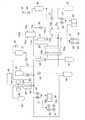
図3は、図1と図2に示す液体加温器を2つ用いた血液分析装置、つまりフローサイトメータを示す構成説明図である。
同図において、先ず、バルブ21を開き、試薬チャンバ22とダイアフラムポンプ23とを連通させる。次に、バルブ24を開くと、陰圧25により試薬(希釈液)がダイアフラムポンプ23に1mLだけ吸引される。バルブ21,24を閉、バルブ26,27を開にすると、陽圧28により1mLの試薬がダイアフラムポンプ23から液体加温器本体100aへニップル15aを介して供給され加熱される。
【0023】
以上の動作を複数回くり返すことにより、所定温度まで上昇した試薬がニップル17aから送出され、サンプリングバルブ29の試薬流路29aを介して反応チャンバ30の手前までの流路を満たす。
【0024】
次に、シリンジ31を作動させ試料チャンバ32から試料(血液)をサンプリングバルブ29の定量流路29bへ吸引する。サンプリングバルブ29を回転させ4μLの試料を定量し、定量流路29bを試薬流路29aと切換える。これによって、試料は試薬によって前後がはさまれる。そこで、上述のようにダイアフラムポンプ23を作動させて本体100aから1mL試薬を送出すると、4μLの試料が1mLの試薬と共に反応チャンバ30に流入し、反応チャンバ30で撹拌されて希釈試料が作成される。
【0025】
次に、バルブ33,34,35を開にし、ダイアフラムポンプ36に陰圧37を印加すると、反応チャンバ30とバルブ34との間の流路が希釈試料で満たされる。バルブ33,34を閉にし、シリンジ38を作動させると、希釈試料はシースフローセル39内のノズル40から吐出される。
【0026】
一方、バルブ57を開にすると、シース液がチャンバ41から陽圧42によりシースフローセル39に供給され、ノズル40から吐出される希釈試料を包み込んで、いわゆる、シースフローを形成する。そのシースフローに発光素子43から光が照射され、希釈試料に含有される粒子からの散乱光や蛍光などの光が受光素子44によって検出される。
【0027】
分析部45は検出された光強度に基づいて希釈試料中の粒子の特徴を分析する。そして、シースフローを形成した希釈試料とシース液は排液チャンバ46へ排出される。
以上のようにして分析動作が終了すると、次に洗浄動作が行われる。
【0028】
まず、バルブ47,48を開にする。洗浄液チャンバ49に陽圧50を印加して洗浄液を、バルブ47,ニップル16a,本体100a,ニップル18a,サンプリングバルブ29,および反応チャンバ30へと流し、反応チャンバ30があふれる前にバルブ47,48を閉にする。
【0029】
バルブ33,34,35を開き、陰圧37をダイアフラムポンプ36に印加して、洗浄液を反応チャンバ30からバルブ33,34を介してダイアフラムポンプ36まで吸引する。バルブ34,35を閉、バルブ51,52を開にして陽圧53をダイアフラムポンプ36に印加すると、ダイアフラムポンプ36の洗浄液はバルブ51を介して排液チャンバ54へ排出される。次に、バルブ55を開くと、反応チャンバ30の残りの洗浄液も排液チャンバ54へ排出される。
【0030】
次にバルブ48,56を開にし、洗浄液チャンバ49に陽圧50を印加すると、洗浄液は洗浄液チャンバ49からバルブ56,液体加温器本体100b,シリンジ38,ノズル40およびシースフローセル39を経て排液チャンバ46へ排出される。このようにして洗浄動作が終了する。なお、洗浄液も試薬と同様に液体加温器で加熱するのは、洗浄液によって流路を冷やさないためである。
【0031】
【発明の効果】
この発明によれば、基板に液体を収容する開口を設け、開口の両側から加熱部材で液体を加熱するようにしたので、構成が簡単で、熱交換効率が高い液体加温器を提供することができる。
【図面の簡単な説明】
【図1】この発明の一実施例の液体加温器を示す分解斜視図である。
【図2】この発明の実施例を制御する電気回路図である。
【図3】図1に示す液体加温器を用いた血液分析装置の構成説明図である。
【符号の説明】
1 基板
2 貫通開口
3 貫通開口
4 第1熱伝導板
5 第2熱伝導板
6 樹脂フィルム
7 樹脂フィルム
8 フィルム状ヒータ
9 フィルム状ヒータ
10 断熱板
11 断熱板
12 Oリング
13 ネジ穴
14 ビス
15 給液口
15a ニップル
16 給液口
16a ニップル
17 排液口
17a ニップル
18 排液口
18a ニップル
19 温度センサ
20 温度センサ
100 本体
101 第1密閉板
102 第2密閉板[0001]
BACKGROUND OF THE INVENTION
The present invention relates to a liquid warmer, for example, in a sample analyzer, applied to warm or keep the temperature of a diluent or a liquid reagent at a predetermined temperature so that the dilution or reaction state of the sample becomes constant. Related to warmers.
[0002]
[Prior art]
As a conventional heater of this type, a cylindrical storage chamber for storing a liquid is provided in a stainless steel or ceramic cubic block, and the liquid in the storage chamber is formed by heaters provided on two opposing surfaces of the block. It is known that a mechanism for guiding the liquid near the wall surface of the storage chamber and a mechanism for separating heated and unheated liquid are installed in the storage chamber in order to control heat transfer to the liquid. (For example, see Utility Model Registration Nos. 2589789 and 2554298).
[0003]
[Problems to be solved by the invention]
An object of the present invention is to provide a liquid warmer that has higher heat exchange efficiency than that of a conventional warmer of this type and that is simple in configuration and easy to manufacture.
[0004]
[Means for Solving the Problems]
The present invention includes a substrate having an opening penetrating from the front surface to the back surface, and first and second sealing plates that seal the opening from both sides of the substrate to form an internal space, andthe first sealing plate is asurface ofthe opening. has afirst heating element for supplying heat to theside or al interior space,the second sealing plate has a second heating member for supplying heat to the interior space from the back side of the opening, the substrate liquidhave a drain port and liquid supply ports for supplying and discharging to the internalspace, the penetration direction of the opening of the substrate, the liquid heating deviceis a direction intersecting the flowing direction of the liquid into the interior space from the liquid supply ports Is to provide.
[0005]
The volume V of the internal space of the heater of the present invention is substantially determined by the product of the area S of the opening and the thickness T of the substrate, and V = ST.
In this invention, when the volume V of liquid is stored in the internal space, the heating member heats the liquid from the entire sides of the opening of area S.
Therefore, when the volume V is constant, the heat exchange efficiency of the liquid can be made extremely high by increasing the opening area S and decreasing the thickness T.
Moreover, since this heater mainly comprises a substrate having an opening and the first and second sealing plates, the configuration is simple and the manufacture is easy.
[0006]
DETAILED DESCRIPTION OF THE INVENTION
In the present invention, each sealing plate may be a heat conductive plate, the heating member may be a film heater, and the heater may be attached to the back surface of the heat conductive plate.
In this case, examples of the material for the heat conductive plate include metals having high heat conductivity, such as aluminum, copper, and silver (however, these metals have low chemical resistance).
A silicon rubber heater can be used as the film heater.
[0007]
When the heater of the present invention is used for reagent heating, the substrate and the first and second sealing plates are required to have chemical resistance. In this case, the substrate is preferably made of a material such as a metal, resin or ceramic having excellent chemical resistance. For example, stainless steel is used for metal, and polyetherimide, polyetherketone, or polyacetal is used for resin. Can be mentioned.
If the resin as described above is used, the substrate can be mass-produced with high accuracy at low cost by a molding process such as injection molding.
[0008]
In addition, in order to make the sealing plate have high chemical resistance and thermal conductivity, each sealing plate is composed of the above-mentioned heat conductive plate, and has a chemical resistant film on its surface, and each heat conductive plate has its It is preferable to install on a board | substrate through a film.
As the chemical-resistant film, for example, a fluororesin film can be used, and the thickness is preferably as thin as possible from the viewpoint of heat conduction, but 0.1 to 0.5 mm is appropriate from the viewpoint of mechanical strength. .
[0009]
It is preferable to provide a packing member such as an O-ring around the opening periphery of the substrate to improve the sealing performance of the opening by the sealing plate.
Moreover, although this invention is further equipped with a heat insulating material and it is preferable to wrap the whole warmer, the leakage and consumption of the unnecessary heat | fever of a heater can be suppressed by covering at least one part of a heating member.
Further, a plurality of openings may be provided in the substrate, and these openings may be sealed with first and second sealing plates via resin films from both sides of the substrate.
[0010]
If a liquid supply port and a liquid discharge port are provided in each of the plurality of formed internal spaces, a liquid heater for a plurality of circuits can be easily configured.
In addition, it is preferable that a nipple is provided at each of the liquid supply port and the liquid discharge port in order to easily connect the piping tube.
[0011]
The present invention will be described in detail below based on the embodiments shown in the drawings. This does not limit the invention.
FIG. 1 is an exploded perspective view of a liquid heater according to an embodiment of the present invention. As shown in the figure, the
[0012]
The
[0013]
[0014]
Further,
[0015]
At the time of assembly, the
[0016]
Thus, the first and second heat
The
[0017]
Further, the
[0018]
Here, the
[0019]
Therefore, when 6 mL of liquid is supplied to the two internal spaces of the
[0020]
FIG. 2 is an electrical wiring diagram for driving the liquid heater of the present invention. The
[0021]
The liquid supplied from the
[0022]
FIG. 3 is a structural explanatory view showing a blood analyzer using two liquid heaters shown in FIGS. 1 and 2, that is, a flow cytometer.
In the figure, first, the
[0023]
By repeating the above operation a plurality of times, the reagent that has risen to a predetermined temperature is sent out from the
[0024]
Next, the
[0025]
Next, when the
[0026]
On the other hand, when the
[0027]
The
When the analysis operation is completed as described above, a cleaning operation is performed next.
[0028]
First, the
[0029]
The
[0030]
Next, when the
[0031]
【The invention's effect】
According to the present invention, an opening for storing a liquid is provided in the substrate, and the liquid is heated by the heating member from both sides of the opening. Therefore, a liquid heater with a simple configuration and high heat exchange efficiency is provided. Can do.
[Brief description of the drawings]
FIG. 1 is an exploded perspective view showing a liquid heater according to an embodiment of the present invention.
FIG. 2 is an electric circuit diagram for controlling an embodiment of the present invention.
FIG. 3 is a configuration explanatory diagram of a blood analyzer using the liquid warmer shown in FIG. 1;
[Explanation of symbols]
DESCRIPTION OF
Claims (10)
Translated fromJapanese基板の両面から開口を密閉して内部空間を形成する第1および第2密閉板とを備え、
第1密閉板は、開口の表面側から内部空間へ熱を供給するための第1加熱部材を有し、
第2密閉板は、開口の裏面側から内部空間へ熱を供給するための第2加熱部材を有し、
基板は内部空間に対して液体を給排する給液口と排液口を有し、
基板の開口の貫通方向が、給液口から内部空間への液体の流入方向と交わる方向である液体加温器。A substrate having an opening penetrating from the front surface to the back surface;
A first and a second sealing plate that form an internal space by sealing the opening from both sides of the substrate;
Thefirst sealing platehas afirst heating element for supplying heat to thesurface or found inside space of the opening,
The second sealing plate has a second heating member for supplying heat from the back side of the opening to the internal space,
Substratewill have a liquid supply port and drain port for supplying and discharging liquid to the internalspace,
A liquid warmer in whichthe penetration direction of the opening of the substrate intersects with the liquidinflow direction from the liquid supply port to the internal space .
第2密閉板は、表面に第2耐薬品性フィルムを有し、第2耐薬品性フィルムを介して基板に設置されてなる請求項1〜3のいずれか1項に記載の液体加温器。The first sealing plate has afirst chemical resistant film on the surface,and is installed on the substrate via the first chemical resistant film,
The liquid heater accordingto any one of claims 1 to3,wherein the second sealing plate has a second chemical-resistant film on a surface thereof and is installed on the substrate viathe second chemical-resistant film. .
第2密閉板と基板との間に介在する第2パッキング部材とをさらに備えてなる請求項1〜4のいずれか1項に記載の液体加温器。Afirst packing member interposed betweenthe first sealing plate and the substrate;
Liquid warmer accordingto any one of claims 1-4, further comprising comprisingasecond packing member interposed betweenthesecond sealing plate andthe substrate.
排液口が内部空間から基板の他方の端面に連通する第2連通孔からなる請求項1〜5のいずれか1項に記載の液体加温器。The liquid supply port comprises a first communication hole that communicates from the internal space to one end face of the substrate,
The liquid heater accordingto any one of claims 1 to5, wherein the drainage port includes a second communication hole communicating with the other end surface of the substrate from the internal space.
Priority Applications (2)
| Application Number | Priority Date | Filing Date | Title |
|---|---|---|---|
| JP2001172964AJP4759168B2 (en) | 2001-06-07 | 2001-06-07 | Liquid heater and analyzer equipped with the same |
| US10/163,388US6694747B2 (en) | 2001-06-07 | 2002-06-04 | Liquid container and an analyzer equipped therewith |
Applications Claiming Priority (1)
| Application Number | Priority Date | Filing Date | Title |
|---|---|---|---|
| JP2001172964AJP4759168B2 (en) | 2001-06-07 | 2001-06-07 | Liquid heater and analyzer equipped with the same |
Publications (2)
| Publication Number | Publication Date |
|---|---|
| JP2002365181A JP2002365181A (en) | 2002-12-18 |
| JP4759168B2true JP4759168B2 (en) | 2011-08-31 |
Family
ID=19014508
Family Applications (1)
| Application Number | Title | Priority Date | Filing Date |
|---|---|---|---|
| JP2001172964AExpired - Fee RelatedJP4759168B2 (en) | 2001-06-07 | 2001-06-07 | Liquid heater and analyzer equipped with the same |
Country Status (2)
| Country | Link |
|---|---|
| US (1) | US6694747B2 (en) |
| JP (1) | JP4759168B2 (en) |
Families Citing this family (13)
| Publication number | Priority date | Publication date | Assignee | Title |
|---|---|---|---|---|
| US8293471B2 (en)* | 2004-01-28 | 2012-10-23 | Marshall University Research Corporation | Apparatus and method for a continuous rapid thermal cycle system |
| US10741034B2 (en) | 2006-05-19 | 2020-08-11 | Apdn (B.V.I.) Inc. | Security system and method of marking an inventory item and/or person in the vicinity |
| JP4977912B2 (en)* | 2007-02-16 | 2012-07-18 | 株式会社Kelk | Fluid temperature controller |
| US20100217550A1 (en)* | 2009-02-26 | 2010-08-26 | Jason Crabtree | System and method for electric grid utilization and optimization |
| US8596340B1 (en)* | 2010-10-13 | 2013-12-03 | Horn-Barber Technologies, LLC | Apparatus for heating liquid samples for analysis |
| US9963740B2 (en) | 2013-03-07 | 2018-05-08 | APDN (B.V.I.), Inc. | Method and device for marking articles |
| US9904734B2 (en) | 2013-10-07 | 2018-02-27 | Apdn (B.V.I.) Inc. | Multimode image and spectral reader |
| CN103645333A (en)* | 2013-12-25 | 2014-03-19 | 嘉善加斯戴克医疗器械有限公司 | Reagent preheating device |
| US10745825B2 (en) | 2014-03-18 | 2020-08-18 | Apdn (B.V.I.) Inc. | Encrypted optical markers for security applications |
| EP3119610B1 (en) | 2014-03-18 | 2024-05-22 | APDN (B.V.I.) Inc. | Encrypted optical markers for security applications |
| CN109070130B (en) | 2016-04-11 | 2022-03-22 | 亚普蒂恩(B V I)公司 | Method for marking cellulose products |
| US10995371B2 (en) | 2016-10-13 | 2021-05-04 | Apdn (B.V.I.) Inc. | Composition and method of DNA marking elastomeric material |
| US10920274B2 (en) | 2017-02-21 | 2021-02-16 | Apdn (B.V.I.) Inc. | Nucleic acid coated submicron particles for authentication |
Family Cites Families (19)
| Publication number | Priority date | Publication date | Assignee | Title |
|---|---|---|---|---|
| JPS4917291A (en)* | 1972-06-05 | 1974-02-15 | ||
| JPS569046U (en)* | 1979-06-29 | 1981-01-26 | ||
| JPS57147059A (en)* | 1981-03-06 | 1982-09-10 | Toshiba Corp | Constant temperature flow cell |
| JPS57163845A (en)* | 1981-04-02 | 1982-10-08 | Toshiba Corp | Thermostatic flow cell |
| US4494380A (en)* | 1984-04-19 | 1985-01-22 | Bilan, Inc. | Thermoelectric cooling device and gas analyzer |
| JP2589789Y2 (en)* | 1991-02-15 | 1999-02-03 | シスメックス株式会社 | Liquid temperature controller for sample analyzer |
| AU643089B2 (en) | 1991-02-15 | 1993-11-04 | Toa Medical Electronics Co., Ltd. | Apparatus for regulating liquid temperature |
| US5232516A (en)* | 1991-06-04 | 1993-08-03 | Implemed, Inc. | Thermoelectric device with recuperative heat exchangers |
| JPH0539645U (en)* | 1991-10-31 | 1993-05-28 | 京セラ株式会社 | Thermostat for physics and chemistry equipment |
| JPH0875726A (en)* | 1994-09-09 | 1996-03-22 | Nippon Steel Corp | Method and apparatus for determining abnormal blood site |
| EP0759141B1 (en)* | 1994-05-13 | 2003-04-16 | Hydrocool Pty. Ltd. | Cooling apparatus |
| JPH08178824A (en) | 1994-12-21 | 1996-07-12 | Toa Medical Electronics Co Ltd | Particle measuring apparatus |
| JPH0961312A (en)* | 1995-08-30 | 1997-03-07 | Mochida Pharmaceut Co Ltd | Simple measuring device |
| US5737923A (en)* | 1995-10-17 | 1998-04-14 | Marlow Industries, Inc. | Thermoelectric device with evaporating/condensing heat exchanger |
| JPH09304265A (en)* | 1996-05-10 | 1997-11-28 | Toa Medical Electronics Co Ltd | Pellet for particle detector and its production |
| US5802856A (en)* | 1996-07-31 | 1998-09-08 | Stanford University | Multizone bake/chill thermal cycling module |
| US5761909A (en)* | 1996-12-16 | 1998-06-09 | The United States Of America As Represented By The Secretary Of The Navy | Breathing gas temperature modification device |
| JP3347977B2 (en)* | 1997-07-02 | 2002-11-20 | フリヂスター株式会社 | Liquid circulation type thermoelectric cooling / heating device |
| US6446442B1 (en)* | 1999-10-07 | 2002-09-10 | Hydrocool Pty Limited | Heat exchanger for an electronic heat pump |
- 2001
- 2001-06-07JPJP2001172964Apatent/JP4759168B2/ennot_activeExpired - Fee Related
- 2002
- 2002-06-04USUS10/163,388patent/US6694747B2/ennot_activeExpired - Lifetime
Also Published As
| Publication number | Publication date |
|---|---|
| US20030000225A1 (en) | 2003-01-02 |
| JP2002365181A (en) | 2002-12-18 |
| US6694747B2 (en) | 2004-02-24 |
Similar Documents
| Publication | Publication Date | Title |
|---|---|---|
| JP4759168B2 (en) | Liquid heater and analyzer equipped with the same | |
| US7892493B2 (en) | Fluid sample transport device with reduced dead volume for processing, controlling and/or detecting a fluid sample | |
| US9110044B2 (en) | System for the integrated and automated analysis of DNA or protein and method for operating said type of system | |
| CN114789639A (en) | Fluid Management Devices | |
| JP2006527369A5 (en) | ||
| RU2010134426A (en) | BATTERY COMPONENTS ASSEMBLY AND METHOD FOR ASSEMBLY OF THE BATTERY COMPONENTS ASSEMBLY | |
| US9012185B2 (en) | Thermal cycling device with phase changing fluids | |
| CN204202237U (en) | Attemperating unit | |
| CN116373554A (en) | Heat exchange modules, thermal management systems, electric vehicles and energy storage systems | |
| CN112322486A (en) | A single-cell nucleic acid processing instrument | |
| CN107735180A (en) | Distributor for analyzer | |
| CN112859953A (en) | Temperature control module in biological reaction instrument | |
| CN115926967A (en) | A fully integrated nucleic acid detection cartridge chip | |
| CN103308502B (en) | Handheld general microfluidic chip real-time detection device and application | |
| US20080135116A1 (en) | Fluid manifolds | |
| CN114618599A (en) | Heating temperature control device and microfluidic system | |
| JP6179723B2 (en) | Pressure sensor inspection equipment | |
| JP2003337626A (en) | Fluid temperature controller | |
| CN103645333A (en) | Reagent preheating device | |
| CN108982754A (en) | Reagent preheating and reaction device and sample analyzer | |
| CN217910516U (en) | A water heating type water bath | |
| CN115537320A (en) | Fully enclosed nucleic acid rapid test paper detection microfluidic chip and its portable system | |
| EP3700673A1 (en) | Fluid thermal processing | |
| CN115044658A (en) | A multi-flux microfluidic PCR amplification device and amplification method | |
| CN111454834B (en) | PCR augmentor |
Legal Events
| Date | Code | Title | Description |
|---|---|---|---|
| A621 | Written request for application examination | Free format text:JAPANESE INTERMEDIATE CODE: A621 Effective date:20080410 | |
| A977 | Report on retrieval | Free format text:JAPANESE INTERMEDIATE CODE: A971007 Effective date:20100804 | |
| A131 | Notification of reasons for refusal | Free format text:JAPANESE INTERMEDIATE CODE: A131 Effective date:20110208 | |
| A521 | Request for written amendment filed | Free format text:JAPANESE INTERMEDIATE CODE: A523 Effective date:20110408 | |
| A01 | Written decision to grant a patent or to grant a registration (utility model) | Free format text:JAPANESE INTERMEDIATE CODE: A01 Effective date:20110517 | |
| A01 | Written decision to grant a patent or to grant a registration (utility model) | Free format text:JAPANESE INTERMEDIATE CODE: A01 | |
| A61 | First payment of annual fees (during grant procedure) | Free format text:JAPANESE INTERMEDIATE CODE: A61 Effective date:20110606 | |
| R150 | Certificate of patent or registration of utility model | Free format text:JAPANESE INTERMEDIATE CODE: R150 | |
| FPAY | Renewal fee payment (event date is renewal date of database) | Free format text:PAYMENT UNTIL: 20140610 Year of fee payment:3 | |
| R250 | Receipt of annual fees | Free format text:JAPANESE INTERMEDIATE CODE: R250 | |
| LAPS | Cancellation because of no payment of annual fees |