JP4758447B2 - Mobile device - Google Patents
Mobile deviceDownload PDFInfo
- Publication number
- JP4758447B2 JP4758447B2JP2008010107AJP2008010107AJP4758447B2JP 4758447 B2JP4758447 B2JP 4758447B2JP 2008010107 AJP2008010107 AJP 2008010107AJP 2008010107 AJP2008010107 AJP 2008010107AJP 4758447 B2JP4758447 B2JP 4758447B2
- Authority
- JP
- Japan
- Prior art keywords
- panel
- mobile terminal
- lock
- dressing
- terminal according
- Prior art date
- Legal status (The legal status is an assumption and is not a legal conclusion. Google has not performed a legal analysis and makes no representation as to the accuracy of the status listed.)
- Expired - Fee Related
Links
Images


Landscapes
- Telephone Set Structure (AREA)
Description
Translated fromJapanese本発明は、携帯端末本体に着せ替えパネルを着脱自在な携帯端末に関し、特に着せ替えパネルの着脱性を改善するものである。 The present invention relates to a portable terminal in which a dressing panel can be freely attached to and detached from a portable terminal body, and in particular, to improve the detachability of the dressing panel.
従来より、外観の着せ替え自在な携帯端末のニーズが増えてきている。このニーズに合わせて携帯端末本体に着せ替えパネルを着脱自在な携帯端末が流通している。 Conventionally, there is an increasing need for portable terminals whose appearance can be freely changed. In order to meet this need, portable terminals with removable dressing panels on the portable terminal main body are in circulation.
例えば、特許文献1によれば、第1及び第2の筐体を開いた第1の状態と、第1及び第2の筐体を閉じた第2の状態とを取り得る折り畳み可能に構成し、第1の筐体と第2の筐体を、第2の状態で隠蔽される内面と、この内面と対向する外面と、内面と外面の間に形成される周側面とをそれぞれ備えた扁平な箱体で構成し、内面と周側面とで一方が解放した主筐体を構成し、主筐体に対して、板状の外面の取付手段を介して着脱可能に構成し、取付手段を主筐体の周側面に設け、筐体の一部を構成する筐体面を交換することでデザインを簡単に変更することが可能な着せ替え形の携帯電話を提供している。
しかしながら、特許文献1では、着せ替えパネルがビス等により固定されているので、脱着するためには常時持ち歩かないドライバーや特殊な道具等が必要となるという問題があった。また、外観に着せ替えパネル固定用のビス等が露出し、デザイン的に制約を受けたり、必ず表側からビス等の脱着をしなければならないという制約もあった。 However, in
本発明は、かかる点に鑑みてなされたものであり、その目的とするところは、ビスを取り外すことなく、脱着を容易に行うことができるようにすると共に、外観をよくすることにある。 This invention is made | formed in view of this point, The place made into the objective is to make it easy to remove | desorb without removing a screw | thread and to improve an external appearance.
上記の目的を達成するために、この発明では、ロックレバーを解除するロック解除ボタンの押圧部を携帯端末本体の開口から露出させるようにした。 In order to achieve the above object, in the present invention, the pressing portion of the lock release button for releasing the lock lever is exposed from the opening of the mobile terminal body.
具体的には、第1の発明では、携帯端末本体に着せ替えパネルを着脱自在な携帯端末を対象とし、
上記携帯端末は、
上記携帯端末本体に形成され、上記着せ替えパネルが嵌め込まれるパネル装着用凹部と、
上記着せ替えパネルに形成された係合爪と、
上記パネル装着用凹部に形成され、上記係合爪が係合する係合穴と、
上記パネル装着用凹部に内蔵され、上記着せ替えパネルをロック部でロックするロックレバーと、
上記着せ替えパネルに形成され、上記ロックレバーのロック部が係合する被ロック部と、
上記ロック部が被ロック部から外れるのを規制する方向に上記ロックレバーを押圧する弾性部材と、
上記弾性部材の付勢力に抗して上記ロックレバーをスライドさせ、上記ロック部と被ロック部との係合を解除すると同時に、上記着せ替えパネルを押し上げるロック解除ボタンと、
上記携帯端末本体の外表面に開口し、上記ロック解除ボタンが挿入されると共に、該ロック解除ボタンの押圧部を露出させるロック解除ボタン用孔部とを備えている。Specifically, in the first invention, the portable terminal body is intended for a portable terminal with a removable dressing panel,
The mobile device
A panel mounting recess formed in the mobile terminal body and into which the dress-up panel is fitted;
An engaging claw formed on the dressing panel;
An engagement hole formed in the panel mounting recess and engaged with the engagement claw;
A lock lever built in the recess for mounting the panel and locking the dressing panel with a lock;
A locked portion that is formed on the dressing panel and engages with a lock portion of the lock lever;
An elastic member that presses the lock lever in a direction that restricts the lock portion from coming off the locked portion;
A lock release button that slides the lock lever against the urging force of the elastic member, releases the engagement between the lock portion and the locked portion, and simultaneously pushes up the dressing panel;
There is an opening on the outer surface of the mobile terminal body, the lock release button is inserted, and a lock release button hole for exposing the pressing portion of the lock release button.
上記の構成によると、着せ替えパネルをパネル装着用凹部に嵌め込むと、着せ替えパネルの係合爪がパネル装着用凹部の係合穴に係合すると共に、弾性部材がロックレバーを押圧することにより、ロック部が被ロック部を確実にロックするので、通常使用時に誤って着せ替えパネルが外れることはない。一方、着せ替え時には、携帯端末本体の外表面に設けたロック解除ボタン用孔部から露出するロック解除ボタンの押圧部を筆記具の先端などで押圧することで、弾性部材を押し戻しながらロック部によるロックを解除すると同時に着せ替えパネルが押し上げられる。このように、身近な筆記具などを利用してロック解除ボタンの押圧部を押圧するだけで、ロック部と被ロック部との係合が解除されると共に着せ替えパネルが浮き上がるので、着せ替えパネルの取り外しが、ビス等を特殊な工具を用いて外すことなく容易に行われる。また、ロックレバー及びロック解除ボタンがパネル装着用凹部に内蔵されて外観に現れないので、見映えがよい。 According to the above configuration, when the dressing panel is fitted into the panel mounting recess, the engaging pawl of the dressing panel engages with the engagement hole of the panel mounting recess and the elastic member presses the lock lever. Thus, the lock portion securely locks the locked portion, so that the dress-up panel is not accidentally detached during normal use. On the other hand, when changing clothes, the lock part is locked while the elastic member is pushed back by pressing the pressing part of the unlocking button exposed from the unlocking button hole provided on the outer surface of the mobile terminal body with the tip of the writing instrument. The dress-up panel is pushed up simultaneously with releasing. In this way, just by pressing the pressing part of the unlocking button using a familiar writing instrument etc., the engagement between the locking part and the locked part is released and the dressing panel floats up. The removal can be easily performed without removing the screw or the like using a special tool. Further, the lock lever and the lock release button are built in the panel mounting recess and do not appear on the appearance, so that the appearance is good.
第2の発明では、第1の発明において、
上記着せ替えパネルは、樹脂成形品よりなるパネル本体に装飾用シートが貼り付けられたものよりなる。In the second invention, in the first invention,
The dress-up panel is formed by attaching a decorative sheet to a panel body made of a resin molded product.
上記の構成によると、パネル本体は、樹脂成形品であるので、軽量で成形が容易であると共に、適度に変形するので着脱がし易く、着せ替えパネルのベースとして適している。一方、パネル本体に装飾用シートを貼り付けるようにしているので、パネル本体は1つの型で成形でき、その共通のパネル本体に様々な種類の装飾用シートを貼り付けるようにすれば、ユーザの好みに応じた多種多様の着せ替えパネルを容易かつ安価に製造することができる。 According to said structure, since a panel main body is a resin molded product, while being lightweight and easy to shape | mold, since it deform | transforms moderately, it is easy to attach or detach and is suitable as a base of a dress-up panel. On the other hand, since the decorative sheet is pasted on the panel main body, the panel main body can be formed with a single mold, and various kinds of decorative sheets can be pasted on the common panel main body. A wide variety of dress-up panels according to preferences can be easily and inexpensively manufactured.
第3の発明では、第2の発明において、
上記装飾用シートは、人工皮革、本革、木、セラミック及びカーボンからなる群から選択された材料よりなる
ことを特徴とする携帯端末。In the third invention, in the second invention,
The mobile terminal is characterized in that the decorative sheet is made of a material selected from the group consisting of artificial leather, genuine leather, wood, ceramic and carbon.
上記の構成によると、ユーザの好みに応じた手触りと外観の装飾用シートが選択可能である。 According to the above configuration, it is possible to select a decorative sheet having a touch and appearance according to the user's preference.
第4の発明では、第2又は第3の発明において、
上記パネル本体の裏面の上記被ロック部の近傍周縁には、引っ掛け用のテーパー面が形成されている。In the fourth invention, in the second or third invention,
A taper surface for hooking is formed in the vicinity of the locked portion on the back surface of the panel body.
上記の構成によると、ロック解除ボタンを押圧して着せ替えパネルが浮き上がったときに、引っ掛け用のテーパー面に筆記部や指の先端を挿入することにより、着せ替えパネルの取り外しが容易に行われる。 According to the above configuration, when the dress-up panel is lifted by pressing the unlock button, the dress-up panel can be easily removed by inserting the writing portion or the tip of the finger into the taper surface for hooking. .
第5の発明では、第1乃至第4のいずれか1つの発明において、
上記ロック解除ボタン及びロックレバーは、ポリアセタールコポリマーで成形されている。In a fifth invention, in any one of the first to fourth inventions,
The unlock button and the lock lever are formed of polyacetal copolymer.
上記の構成によると、ポリアセタールコポリマーは結晶性が高く、熱可塑性のあるエンジニアリングプラスチックの一種で、バランスのとれた機械的性質を持ち、耐疲労性と耐摩擦摩耗特性に優れているので、繰り返し着せ替えパネルを着脱することによるロック解除ボタン及びロックレバーの損傷が防止される。 According to the above configuration, polyacetal copolymer is a kind of engineering plastic with high crystallinity and thermoplasticity, balanced mechanical properties, and excellent fatigue resistance and frictional wear characteristics. The lock release button and the lock lever are prevented from being damaged by attaching / detaching the replacement panel.
第6の発明では、第1乃至第4のいずれか1つの発明において、
上記ロック解除ボタンは、金属で形成され、ロックレバーは、ポリアセタールコポリマーで成形されている。In a sixth invention, in any one of the first to fourth inventions,
The lock release button is made of metal, and the lock lever is made of polyacetal copolymer.
上記の構成によると、ロック解除ボタンを金属で構成することで剛性及び耐久性が向上し、先の尖ったもので操作しても傷が付き難い。また、ポリアセタールコポリマーは結晶性が高く、熱可塑性のあるエンジニアリングプラスチックの一種で、バランスのとれた機械的性質を持ち、耐疲労性と耐摩擦摩耗特性に優れているので、繰り返し着せ替えパネルを着脱することによるロックレバーの損傷が防止される。 According to said structure, rigidity and durability improve by comprising a lock release button with a metal, and even if it operates with a pointed thing, it is hard to be damaged. Polyacetal copolymer is a kind of engineering plastic with high crystallinity and thermoplasticity, balanced mechanical properties, and excellent fatigue and frictional wear characteristics. This prevents the lock lever from being damaged.
第7の発明では、第1乃至第6のいずれか1つの発明において、
上記弾性部材は、圧縮コイルバネよりなる。In a seventh invention, in any one of the first to sixth inventions,
The elastic member is a compression coil spring.
上記の構成によると、簡単な構成で耐久性のある弾性部材が得られる。 According to the above configuration, a durable elastic member can be obtained with a simple configuration.
第8の発明では、第1乃至第7のいずれか1つの発明において、
上記ロック解除ボタンの押圧部には、押圧用凹部が形成されている。In an eighth invention, in any one of the first to seventh inventions,
A pressing recess is formed in the pressing portion of the lock release button.
上記の構成によると、押圧用凹部に筆記具や爪楊枝の先端を差し込んだときに、筆記具や爪楊枝の先端が押圧用凹部から外れにくくなるので、ロック解除ボタンが押しやすい。 According to said structure, when the front-end | tip of a writing tool or a toothpick is inserted in the recessed part for a press, since the front-end | tip of a writing instrument or a toothpick becomes difficult to remove | deviate from a recessed part for a press, a lock release button is easy to push.
第9の発明では、第1乃至第8のいずれか1つの発明において、
上記着せ替えパネルは、表示部の背面に設けられている。In a ninth invention, in any one of the first to eighth inventions,
The dress-up panel is provided on the back surface of the display unit.
上記の構成によると、表示部の背面側は、カメラなどが設けられることが少ないので、背面側全体を着せ替えパネルとすることが可能であり、着せ替えパネルの構成が簡単なものとなる。 According to the above configuration, a camera or the like is rarely provided on the back side of the display unit, so that the entire back side can be used as a dress-up panel, and the configuration of the dress-up panel becomes simple.
第10の発明では、第1乃至第9のいずれか1つの発明において、
上記ロックレバー側の係合穴には、板バネが突設されている。In a tenth invention, in any one of the first to ninth inventions,
A leaf spring projects from the engagement hole on the lock lever side.
上記の構成によると、携帯端末本体と別部品の板バネを設けることで、パネル保持力が容易に調整可能となる。また、板バネの付勢力により、パネル装着用凹部の中で着せ替えパネルが、がたつくことはない。さらに、着せ替えパネルを押し上げた後に、板バネの突部に係合爪が乗り上げるので、着せ替えパネルがパネル装着用凹部に戻ることなく、ロック解除状態が保持され、着せ替えパネルの取り外しが容易になる。 According to said structure, a panel holding force can be adjusted easily by providing the leaf | plate spring of a separate component from a portable terminal main body. Further, the dressing panel does not rattle in the panel mounting recess due to the urging force of the leaf spring. In addition, after pushing up the dressing panel, the engaging claws ride on the protrusions of the leaf springs, so the dressing panel does not return to the panel mounting recess and the unlocked state is maintained, making it easy to remove the dressing panel. become.
第11の発明では、第1乃至第10のいずれか1つの発明において、
携帯端末は、携帯電話機とする。In an eleventh invention, in any one of the first to tenth inventions,
The mobile terminal is a mobile phone.
上記の構成によると、頻繁に携帯する携帯電話機の外観をTPOに合わせて着せ替えすることができるので、その商品性が格段に向上する。 According to said structure, since the external appearance of the mobile telephone carried frequently can be changed according to TPO, the commercial property improves markedly.
以上説明したように、本発明によれば、着せ替えパネルをパネル装着用凹部にロックするロックレバーと、弾性部材の付勢力に抗してロックレバーをスライドさせ、ロック部と被ロック部との係合を解除すると同時に、着せ替えパネルを押し上げるロック解除ボタンとを設け、このロック解除ボタンを携帯端末本体の外表面に開口するロック解除ボタン用孔部に挿入し、その押圧部を露出させるようにしたことにより、押圧部を押圧すれば、ロック解除ボタンが、ロック部と被ロック部との係合の解除と、着せ替えパネルをパネル装着用凹部から取り外すことの2つの動作を同時に行うので、ビスを取り外すことなく、筆記具などの身近な道具を利用して着せ替えパネルの脱着を容易に行うことができると共に、着せ替えパネルをロックする機構が外観に現れないので、見映えを向上させることができる。 As described above, according to the present invention, the lock lever that locks the dressing panel in the panel mounting recess, and the lock lever is slid against the urging force of the elastic member, so that the lock portion and the locked portion A lock release button that pushes up the dressing panel at the same time as releasing the engagement is provided, and the lock release button is inserted into the hole for the lock release button that opens on the outer surface of the mobile terminal body so that the pressing portion is exposed. As a result, if the pressing part is pressed, the lock release button simultaneously performs two operations of releasing the engagement between the lock part and the locked part and removing the dressing panel from the panel mounting recess. Without changing the screw, it is possible to easily attach and detach the dress-up panel using familiar tools such as writing instruments, and lock the dress-up panel. Since configuration is not shown on the outward appearance, it can be improved visual quality.
以下、本発明の実施形態を図面に基づいて説明する。 Hereinafter, embodiments of the present invention will be described with reference to the drawings.
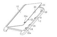
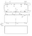
図1乃至図3は本発明の実施形態の携帯端末としての携帯電話機1を示し、この携帯電話機1は、表示部2を有する第1の筐体3と、操作部4を有する第2の筐体5とが、ヒンジ部6を中心に折り畳み開閉自在に構成されている。第1の筐体3は、携帯端末本体としての矩形状の表示部側キャビネット7を備え、この表示部側キャビネット7は、樹脂成形品やマグネシウム合金等よりなる。表示部側キャビネット7の表面側は、表示部2を保護する透明な表示部カバー2aで覆われている。表示部側キャビネット7の背面側は、着せ替えパネル10で覆われている。 1 to 3 show a
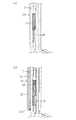
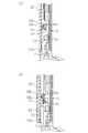
図4〜図7に図3に示す携帯電話機1の(a)着せ替えパネル10を装着したときと、(b)着せ替えパネルを押し上げたときの側方から見た拡大側面図又は断面図を示す。図9及び図10に図8に示した断面で切断したときの、(a)着せ替えパネル10を装着したときと、(b)着せ替えパネルを押し上げたときの下方から見た拡大断面図を示す。図11に着せ替えパネルの分解平面図を示す。 FIGS. 4 to 7 are an enlarged side view or a cross-sectional view as viewed from the side when (a) the
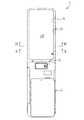
図11に示すように、着せ替えパネル10は、ポリカーボネイト(PC)やABS樹脂を材料とする樹脂成形品よりなる略矩形状のパネル本体11に装飾用シート12が貼り付けられたものよりなる。なお、図2では、装飾用シート12は省略している。パネル本体11は、樹脂成形品であるので、軽量で成形が容易であると共に、適度に変形するので着脱がし易く、着せ替えパネル10のベースとして適している。装飾用シート12は、例えば、人工皮革、本革、木、セラミック、カーボンなどからなり、その裏面側に両面テープ(図示せず)が貼り付けられている。このように、パネル本体11に装飾用シート12を貼り付けるようにしているので、パネル本体11は1つの型で成形でき、その共通のパネル本体11に様々な種類の装飾用シート12を貼り付けるようにすれば、ユーザの好みに応じた多種多様の触りと外観の着せ替えパネル10を容易かつ安価に製造することができる。 As shown in FIG. 11, the dress-up
着せ替えパネル10は、表示部側キャビネット7の背面側に形成した略矩形状のパネル装着用凹部8に嵌め込まれている。着せ替えパネル10は、カメラなどが設けられることが少ない表示部2の背面に設けられているので、背面側のほぼ全体を着せ替えパネル10とすることが可能であり、着せ替えパネル10の構成が簡単なものとなっている。 The dressing
パネル装着用凹部8には、複数の(本実施形態では、6つの)係合穴9,19が形成されている。これに対応して、図12にも示すように、パネル本体11には、係合穴9,19に係合する係合爪13,13が突出して形成されている。具体的には、図9に示すように、右側の2つの係合穴19には、金属製の板バネ20がパネル装着用凹部8の表面から突出するように設けられ、これに対応する係合爪23に設けた凹みに板バネ20の突部が嵌合するようになっている。このように、表示部側キャビネット7と別部品の板バネ20を設けることで、着せ替えパネル10の保持力が容易に調整可能となっている。また、図10に示すように、係合爪13と係合穴9とが互いに係合するようになっている。 A plurality (six in this embodiment) of
パネル装着用凹部8には、ロックレバー挿入用開口14が貫通形成されている。このロックレバー挿入用開口14内には、図13に示すロックレバー15が内蔵されている。このロックレバー15は、軸部15aと、この軸部15aから垂直に延びるロック部15bとを備え、軸部15aが表示部側キャビネット7の上下方向に延び、ロック部15bが表示部側キャビネット7の表裏方向に延びるように配置されている。また、ロックレバー15は、表示部側キャビネット7の上下方向にスライド可能なように配置されると共に、ロック部15bの先端で着せ替えパネル10をロック可能に構成されている。 A lock
図7で拡大して示すように、パネル本体11には、ロックレバー15のロック部15bが係合する被ロック部11aが形成されている。また、図5に示すように、ロックレバー挿入用開口14の内部には、ロック部15bが被ロック部11aから外れるのを規制する方向(つまり表示部側キャビネット7の上方向)にロックレバー15を押圧する弾性部材としての圧縮コイルバネ16が内蔵されている。圧縮コイルバネ16は、簡単な構成で耐久性があるため、弾性部材として適している。また、巻き数を調整することで、表示部側キャビネット7の厚みを厚くすることなく、バネ定数を増加させることができる。 As shown in an enlarged view in FIG. 7, the panel
表示部側キャビネット7の外表面には、ロック解除ボタン用孔部17が開口している。正確には、表示部カバー2aにロック解除ボタン用孔部17が開口し、このロック解除ボタン用孔部17は、ロックレバー挿入用開口14に連通している。ロック解除ボタン用孔部17の内部には、圧縮コイルバネ16の付勢力に抗してロックレバー15をスライドさせると共に、着せ替えパネル10を押し上げるロック解除ボタン18が内蔵されている。ロック解除ボタン用孔部17からロック解除ボタン18の円柱状の押圧部が露出している。図14に示すように、ロック解除ボタン18の押圧部の先端には、丸く押圧用凹部18aが凹陥されている。押圧用凹部18aの反対側には、ロック部15bを押し上げて被ロック部11aとの係合を解除させるレバー押圧部18bが突設されている。レバー押圧部18bは、被ロック部11aを押し上げる直方体状の押上部18cの表面の一部から突出している。 On the outer surface of the display
上記パネル本体11の裏面の上記被ロック部11aの近傍の角部には、扇状に薄肉となるようにテーパー面11bが形成されている。このことで、ロック解除ボタン18を押圧して着せ替えパネル10が浮き上がったときに、テーパー面11bに筆記部や指の先端を挿入することにより、着せ替えパネル10の取り外しが容易に行われるようになっている。テーパー面11bの位置は、必ずしも角部でなくてもよく、角部からある程度ずれたパネル本体11の周縁でもよい。また、その形状は扇状に限定されず、三角形等でもよく、要は筆記部や指の先端を引っ掛け易くする形状であればよい。 A
ロック解除ボタン18及びロックレバー15は、ポリアセタールコポリマーで成形されている。ポリアセタールコポリマーは結晶性が高く、熱可塑性のあるエンジニアリングプラスチックの一種で、バランスのとれた機械的性質を持ち、耐疲労性と耐摩擦摩耗特性に優れているので、繰り返し着せ替えパネル10を着せ替えることによるロック解除ボタン18及びロックレバー15の損傷が防止される。 The
−着せ替えパネルの着脱方法−
次に、本実施形態にかかる着せ替えパネルの着脱方法について説明する。-Attaching / detaching dress-up panel-
Next, a method for attaching and detaching the dressing panel according to the present embodiment will be described.
着せ替えパネル10を取り付けるときには、まず、図2に示すように、着せ替えパネル10の左側の係合爪13をパネル装着用凹部8の係合穴9に係合させた後、右側の係合爪13をパネル装着用凹部8の係合穴9に係合させながら、着せ替えパネル10をパネル装着用凹部8に嵌め込む。この装着状態では、図9(a)に示すように、係合爪23に設けた凹みに板バネ20の突部が嵌合することで、着せ替えパネルが左右方向に固定されるので、パネル装着用凹部8の中で着せ替えパネル10が、がたつかない。また、図10(a)に示すように、係合爪13が係合穴9に係合する。また、図7(a)に示すように、被ロック部11aの下面がロック部15bのテーパを押圧し、図5(a)に示すように、圧縮コイルバネ16を押し戻しながら、ロックレバー15を下方へ移動させる。被ロック部11aがロック部15bを越えると、ロックレバー15が圧縮コイルバネ16に押されて元に戻り、ロック部15bが被ロック部11aに係合する。このように、圧縮コイルバネ16がロックレバー15を押圧することにより、ロック部15bが被ロック部11aを確実にロックするので、通常使用時に誤って着せ替えパネル10が外れることはない。 When attaching the dressing
一方、着せ替え時には、まず、図3に示す表示部側キャビネット7の外表面に設けたロック解除ボタン用孔部17から露出するロック解除ボタン18の押圧用凹部18aを筆記具の先端などで押圧する。すると、図6に示すように、突出するレバー押圧部18bがロック部15bの先端裏面側を押圧してロックレバー15を白矢印の方向へ移動させる。このとき、図5(b)に示すように、軸部15aが圧縮コイルバネ16を押し戻しながら移動し、図7(b)に示すように、ロック部15bと被ロック部11aとのロックが解除される。ロック解除ボタン18の押圧部には、押圧用凹部18aが形成されているので、押圧用凹部18aに筆記具や爪楊枝の先端を差し込んだときに、筆記具や爪楊枝の先端が押圧用凹部18aから外れにくくなるので、ロック解除ボタン18が押しやすい。 On the other hand, when changing clothes, first, the
その後、さらに押上部18cが被ロック部11aを押し上げるので、着せ替えパネル10が押し上げられる。すると、図7(b)に示すように、着せ替えパネル10が押し出される途中から着せ替えパネル10を押し上げる方向に板バネ20が係合爪23を付勢するので、着せ替えパネル10が容易に外れる。着せ替えパネル10が外れた後は、板バネ20の突部に係合爪23が乗り上げるので、着せ替えパネル10がパネル装着用凹部8に戻ることなく、ロック解除状態が保持される。そして、テーパー面11bと表示部側キャビネット7との間に隙間ができるので、その隙間に指の先端などを挿入することで、着せ替えパネル10の取り外しが可能となる。 Thereafter, the push-up
このように、身近な筆記具などを利用してロック解除ボタン18の押圧用凹部18aを押圧するだけで、ロック部15bと被ロック部11aとのロックの解除と、着せ替えパネル10をパネル装着用凹部8から取り外すという2つの動作を同時に行うので、着せ替えパネル10の取り外しが特殊な工具を用いることなく極めて容易に行われる。 In this way, by simply pressing the
最後に着せ替えパネル10を交換して再び上記と同様に取り付けることによって着せ替えが行われる。 Finally, the dress-up
−実施形態の効果−
したがって、本実施形態にかかる携帯電話機1によると、着せ替えパネル10をパネル装着用凹部8にロックするロックレバー15と、圧縮コイルバネ16の付勢力に抗してロックレバー15をスライドさせ、ロック部15bと被ロック部11aとの係合を解除すると同時に、着せ替えパネル10を押し上げるロック解除ボタン18とを設け、このロック解除ボタン18を表示部側キャビネット7の外表面に開口するロック解除ボタン用孔部17に挿入し、その押圧用凹部18aを露出させるようにしたことにより、押圧用凹部18aを押圧すれば、ロック解除ボタン18が、ロック部15bと被ロック部11aとの係合の解除と、着せ替えパネル10をパネル装着用凹部8から取り外すことの2つの動作を同時に行うので、ビスを取り外すことなく、筆記具などの身近な道具を利用して着せ替えパネル10の脱着を容易に行うことができると共に、着せ替えパネル10をロックする機構が外観に現れないので、見映えを向上させることができる。-Effect of the embodiment-
Therefore, according to the
(その他の実施形態)
本発明は、上記実施形態について、以下のような構成としてもよい。(Other embodiments)
The present invention may be configured as follows with respect to the above embodiment.
上記実施形態では、着せ替えパネル10の着せ替えを筆記具の先端などで行えるようにしているが、ロック解除ボタン用孔部17に挿入してロック解除ボタン18を押圧する突起部と、パネル本体11のテーパー面11bに差し込んで着せ替えパネル10を剥がす薄肉部とを備えた専用工具を備品として備えるようにしてもよい。このことで、着せ替えパネル10と同時に持ち歩いている専用工具を利用し、ロック解除ボタン18を突起部で押圧し、浮き上がった着せ替えパネル10のテーパー面11bを薄肉部で押し上げることにより、着せ替えパネル10の取り外しが確実かつ容易に行われる。 In the above embodiment, the dressing
上記実施形態では、ロック解除ボタン18をポリアセタールコポリマーで成形したが、金属で成形してもよい。このことで、ロック解除ボタン18の剛性及び耐久性が向上し、先の尖ったもので操作しても傷が付き難くなる。 In the above embodiment, the
上記実施形態では、携帯端末は、携帯電話機としたが、PHS、PDA、PC、モバイルツール、電子辞書、電卓、複写機等であってもよい。 In the above embodiment, the mobile terminal is a mobile phone, but it may be a PHS, PDA, PC, mobile tool, electronic dictionary, calculator, copier, or the like.
なお、以上の実施形態は、本質的に好ましい例示であって、本発明、その適用物や用途の範囲を制限することを意図するものではない。 In addition, the above embodiment is an essentially preferable illustration, Comprising: It does not intend restrict | limiting the range of this invention, its application thing, or a use.
1 携帯電話機(携帯端末)
7 表示部側キャビネット(携帯端末本体)
8 パネル装着用凹部
9,19 係合穴
10 着せ替えパネル
11 パネル本体
11a 被ロック部
11b テーパー面
12 装飾用シート
13,23 係合爪
15 ロックレバー
15b ロック部
16 圧縮コイルバネ(弾性部材)
17 ロック解除ボタン用孔部
18 ロック解除ボタン
18a 押圧用凹部
20 板バネ1 Mobile phone (mobile terminal)
7 Display side cabinet (mobile terminal body)
DESCRIPTION OF
17 Lock
Claims (11)
Translated fromJapanese上記携帯端末本体に形成され、上記着せ替えパネルが嵌め込まれるパネル装着用凹部と、
上記着せ替えパネルに形成された係合爪と、
上記パネル装着用凹部に形成され、上記係合爪が係合する係合穴と、
上記パネル装着用凹部に内蔵され、上記着せ替えパネルをロック部でロックするロックレバーと、
上記着せ替えパネルに形成され、上記ロックレバーのロック部が係合する被ロック部と、
上記ロック部が被ロック部から外れるのを規制する方向に上記ロックレバーを押圧する弾性部材と、
上記弾性部材の付勢力に抗して上記ロックレバーをスライドさせ、上記ロック部と被ロック部との係合を解除すると同時に、上記着せ替えパネルを押し上げるロック解除ボタンと、
上記携帯端末本体の外表面に開口し、上記ロック解除ボタンが挿入されると共に、該ロック解除ボタンの押圧部を露出させるロック解除ボタン用孔部とを備えている
ことを特徴とする携帯端末。In a portable terminal with a removable dressing panel on the portable terminal body,
A panel mounting recess formed in the mobile terminal body and into which the dress-up panel is fitted;
An engaging claw formed on the dressing panel;
An engagement hole formed in the panel mounting recess and engaged with the engagement claw;
A lock lever built in the recess for mounting the panel and locking the dressing panel with a lock;
A locked portion that is formed on the dressing panel and engages with a lock portion of the lock lever;
An elastic member that presses the lock lever in a direction that restricts the lock portion from coming off the locked portion;
A lock release button that slides the lock lever against the urging force of the elastic member, releases the engagement between the lock portion and the locked portion, and simultaneously pushes up the dressing panel;
A portable terminal comprising: an opening on an outer surface of the portable terminal main body, the unlocking button being inserted therein, and an unlocking button hole exposing the pressing portion of the unlocking button.
上記着せ替えパネルは、樹脂成形品よりなるパネル本体に装飾用シートが貼り付けられたものよりなる
ことを特徴とする携帯端末。The mobile terminal according to claim 1,
The dressing panel comprises a panel body made of a resin molded product and a decorative sheet attached to the panel body.
上記装飾用シートは、人工皮革、本革、木、セラミック及びカーボンからなる群から選択された材料よりなる
ことを特徴とする携帯端末。The mobile terminal according to claim 2,
The mobile terminal is characterized in that the decorative sheet is made of a material selected from the group consisting of artificial leather, genuine leather, wood, ceramic and carbon.
上記パネル本体の裏面の上記被ロック部の近傍周縁には、引っ掛け用のテーパー面が形成されている
ことを特徴とする携帯端末。In the portable terminal according to claim 2 or 3,
A portable terminal, wherein a hooking taper surface is formed on a peripheral edge of the back surface of the panel body in the vicinity of the locked portion.
上記ロック解除ボタン及びロックレバーは、ポリアセタールコポリマーで成形されている
ことを特徴とする携帯端末。The mobile terminal according to any one of claims 1 to 4,
The mobile terminal characterized in that the lock release button and the lock lever are formed of polyacetal copolymer.
上記ロック解除ボタンは、金属で形成され、ロックレバーは、ポリアセタールコポリマーで成形されている
ことを特徴とする携帯端末。The mobile terminal according to any one of claims 1 to 4,
The mobile terminal according to claim 1, wherein the lock release button is made of metal, and the lock lever is molded of polyacetal copolymer.
上記弾性部材は、圧縮コイルバネよりなる
ことを特徴とする携帯端末。The mobile terminal according to any one of claims 1 to 6,
The portable terminal characterized in that the elastic member comprises a compression coil spring.
上記ロック解除ボタンの押圧部には、押圧用凹部が形成されている
ことを特徴とする携帯端末。The mobile terminal according to any one of claims 1 to 7,
A portable terminal characterized in that a pressing recess is formed in the pressing portion of the lock release button.
上記着せ替えパネルは、表示部の背面に設けられている
ことを特徴とする携帯端末。The mobile terminal according to any one of claims 1 to 8,
The portable terminal characterized in that the dress-up panel is provided on the back surface of the display unit.
上記ロックレバー側の係合穴には、板バネが突設されている
ことを特徴とする携帯端末。The mobile terminal according to any one of claims 1 to 9,
A portable terminal characterized in that a leaf spring projects from the engagement hole on the lock lever side.
携帯電話機である
ことを特徴とする携帯端末。The mobile terminal according to any one of claims 1 to 10,
A mobile terminal characterized by being a mobile phone.
Priority Applications (1)
| Application Number | Priority Date | Filing Date | Title |
|---|---|---|---|
| JP2008010107AJP4758447B2 (en) | 2008-01-21 | 2008-01-21 | Mobile device |
Applications Claiming Priority (1)
| Application Number | Priority Date | Filing Date | Title |
|---|---|---|---|
| JP2008010107AJP4758447B2 (en) | 2008-01-21 | 2008-01-21 | Mobile device |
Publications (2)
| Publication Number | Publication Date |
|---|---|
| JP2009171489A JP2009171489A (en) | 2009-07-30 |
| JP4758447B2true JP4758447B2 (en) | 2011-08-31 |
Family
ID=40972122
Family Applications (1)
| Application Number | Title | Priority Date | Filing Date |
|---|---|---|---|
| JP2008010107AExpired - Fee RelatedJP4758447B2 (en) | 2008-01-21 | 2008-01-21 | Mobile device |
Country Status (1)
| Country | Link |
|---|---|
| JP (1) | JP4758447B2 (en) |
Families Citing this family (1)
| Publication number | Priority date | Publication date | Assignee | Title |
|---|---|---|---|---|
| JP6883940B2 (en)* | 2015-10-09 | 2021-06-09 | スリーエム イノベイティブ プロパティズ カンパニー | Goods, how to make goods, how to attach goods |
Family Cites Families (3)
| Publication number | Priority date | Publication date | Assignee | Title |
|---|---|---|---|---|
| JP2972626B2 (en)* | 1997-02-28 | 1999-11-08 | 埼玉日本電気株式会社 | Battery attachment / detachment mechanism |
| JP4566118B2 (en)* | 2005-11-15 | 2010-10-20 | 京セラ株式会社 | Small electronic equipment |
| JP2007306104A (en)* | 2006-05-09 | 2007-11-22 | Sony Ericsson Mobilecommunications Japan Inc | Mobile terminal and decoration panel thereof |
- 2008
- 2008-01-21JPJP2008010107Apatent/JP4758447B2/ennot_activeExpired - Fee Related
Also Published As
| Publication number | Publication date |
|---|---|
| JP2009171489A (en) | 2009-07-30 |
Similar Documents
| Publication | Publication Date | Title |
|---|---|---|
| EP1858233B1 (en) | Battery cover locking device and mobile terminal having the same | |
| US8625287B2 (en) | Portable electronic device with chip card ejecting mechanism | |
| EP1028574B1 (en) | Radio telephone | |
| US20160206065A1 (en) | Mobile electronic device case wallet | |
| US20060104021A1 (en) | PDA carrying device | |
| US7752712B2 (en) | Hinge | |
| WO2008036783A2 (en) | Key organizing device | |
| US20060100005A1 (en) | PDA carrying case | |
| CN105683464A (en) | Portable wireless key | |
| JP2012015533A (en) | Cover and housing | |
| CN101741932A (en) | Sliding Portable Terminal | |
| JP2002057770A (en) | Wireless telephone set | |
| JP4758447B2 (en) | Mobile device | |
| US8257851B2 (en) | Battery cover latch mechanism and portable electronic device using the same | |
| US8435663B2 (en) | Battery ejector and electronic device using the same | |
| CN102238462A (en) | Hearing aid with a casing | |
| US20060287013A1 (en) | Battery fastening apparatus and portable terminal using the same | |
| CN107407104A (en) | Fixing structure of ring member and electronic key | |
| US20050271200A1 (en) | Latching assembly for a removable cover of a portable electronic device | |
| US20110157836A1 (en) | Electronic device and component | |
| US8353540B2 (en) | Battery cover latching mechanism for portable electronic device | |
| CN216490618U (en) | phone case | |
| JP4487217B2 (en) | Belt clip for mobile devices | |
| KR200357038Y1 (en) | Mobile phone strap having magnifier | |
| CN2626146Y (en) | Mobile phone with replaceable shell and its assembly |
Legal Events
| Date | Code | Title | Description |
|---|---|---|---|
| A621 | Written request for application examination | Free format text:JAPANESE INTERMEDIATE CODE: A621 Effective date:20100218 | |
| A977 | Report on retrieval | Free format text:JAPANESE INTERMEDIATE CODE: A971007 Effective date:20110418 | |
| A01 | Written decision to grant a patent or to grant a registration (utility model) | Free format text:JAPANESE INTERMEDIATE CODE: A01 Effective date:20110510 | |
| A61 | First payment of annual fees (during grant procedure) | Free format text:JAPANESE INTERMEDIATE CODE: A61 Effective date:20110602 | |
| R150 | Certificate of patent or registration of utility model | Free format text:JAPANESE INTERMEDIATE CODE: R150 | |
| FPAY | Renewal fee payment (event date is renewal date of database) | Free format text:PAYMENT UNTIL: 20140610 Year of fee payment:3 | |
| LAPS | Cancellation because of no payment of annual fees |