JP4758173B2 - Ligation device - Google Patents
Ligation deviceDownload PDFInfo
- Publication number
- JP4758173B2 JP4758173B2JP2005232253AJP2005232253AJP4758173B2JP 4758173 B2JP4758173 B2JP 4758173B2JP 2005232253 AJP2005232253 AJP 2005232253AJP 2005232253 AJP2005232253 AJP 2005232253AJP 4758173 B2JP4758173 B2JP 4758173B2
- Authority
- JP
- Japan
- Prior art keywords
- pressing member
- sheath
- clip
- clip claw
- claw member
- Prior art date
- Legal status (The legal status is an assumption and is not a legal conclusion. Google has not performed a legal analysis and makes no representation as to the accuracy of the status listed.)
- Expired - Fee Related
Links
Images


Classifications
- A—HUMAN NECESSITIES
- A61—MEDICAL OR VETERINARY SCIENCE; HYGIENE
- A61B—DIAGNOSIS; SURGERY; IDENTIFICATION
- A61B17/00—Surgical instruments, devices or methods
- A61B17/12—Surgical instruments, devices or methods for ligaturing or otherwise compressing tubular parts of the body, e.g. blood vessels or umbilical cord
- A61B17/122—Clamps or clips, e.g. for the umbilical cord
- A61B17/1227—Spring clips
- A—HUMAN NECESSITIES
- A61—MEDICAL OR VETERINARY SCIENCE; HYGIENE
- A61B—DIAGNOSIS; SURGERY; IDENTIFICATION
- A61B17/00—Surgical instruments, devices or methods
- A61B17/12—Surgical instruments, devices or methods for ligaturing or otherwise compressing tubular parts of the body, e.g. blood vessels or umbilical cord
- A61B17/122—Clamps or clips, e.g. for the umbilical cord
- A—HUMAN NECESSITIES
- A61—MEDICAL OR VETERINARY SCIENCE; HYGIENE
- A61B—DIAGNOSIS; SURGERY; IDENTIFICATION
- A61B17/00—Surgical instruments, devices or methods
- A61B17/12—Surgical instruments, devices or methods for ligaturing or otherwise compressing tubular parts of the body, e.g. blood vessels or umbilical cord
- A61B17/128—Surgical instruments, devices or methods for ligaturing or otherwise compressing tubular parts of the body, e.g. blood vessels or umbilical cord for applying or removing clamps or clips
- A61B17/1285—Surgical instruments, devices or methods for ligaturing or otherwise compressing tubular parts of the body, e.g. blood vessels or umbilical cord for applying or removing clamps or clips for minimally invasive surgery
- A—HUMAN NECESSITIES
- A61—MEDICAL OR VETERINARY SCIENCE; HYGIENE
- A61B—DIAGNOSIS; SURGERY; IDENTIFICATION
- A61B90/00—Instruments, implements or accessories specially adapted for surgery or diagnosis and not covered by any of the groups A61B1/00 - A61B50/00, e.g. for luxation treatment or for protecting wound edges
- A61B90/03—Automatic limiting or abutting means, e.g. for safety
- A61B2090/037—Automatic limiting or abutting means, e.g. for safety with a frangible part, e.g. by reduced diameter
Landscapes
- Health & Medical Sciences (AREA)
- Surgery (AREA)
- Life Sciences & Earth Sciences (AREA)
- Heart & Thoracic Surgery (AREA)
- Molecular Biology (AREA)
- Vascular Medicine (AREA)
- Engineering & Computer Science (AREA)
- Biomedical Technology (AREA)
- Reproductive Health (AREA)
- Medical Informatics (AREA)
- Nuclear Medicine, Radiotherapy & Molecular Imaging (AREA)
- Animal Behavior & Ethology (AREA)
- General Health & Medical Sciences (AREA)
- Public Health (AREA)
- Veterinary Medicine (AREA)
- Surgical Instruments (AREA)
- Endoscopes (AREA)
Description
Translated fromJapanese本発明は、クリップによって体内の生体組織を結紮するようにした結紮装置に関する。 The present invention relates to a ligation apparatus configured to ligate a living body tissue with a clip.
従来、クリップによって体内の生体組織を結紮するようにした内視鏡用結紮装置の例として、特許文献1(特開2004−121485)や特許文献2(WO 03/030746 A1)に示される内視鏡用結紮装置が知られている。 Conventionally, as an example of an endoscopic ligation apparatus in which a living body tissue in a body is ligated by a clip, an endoscope shown in Patent Document 1 (Japanese Patent Laid-Open No. 2004-121485) and Patent Document 2 (WO 03/030746 A1). Mirror ligation devices are known.
特許文献1の内視鏡用結紮装置のクリップは、開脚するように付勢されたアームからなり、生体組織を結紮した状態のアームに押え管を嵌着し、閉じた結紮状態にクリップを維持するようになっている。また、特許文献2の内視鏡用結紮装置のクリップは、クリップ脚基部をコイル状のシース内に引き込むことにより、クリップ脚部を閉じて生体組織を結紮し、この状態に維持するようになっている。
特許文献1の内視鏡用結紮装置のクリップにあっては、一旦、押え管をアームに嵌着してクリップを閉じてしまうと、再びクリップを開くことができなくなり、生体組織の掴み直しが効かない。 In the clip of the endoscope ligation apparatus of Patent Document 1, once the presser tube is fitted to the arm and the clip is closed, the clip cannot be opened again, and the living tissue is re-gripped. It does not work.
一方、特許文献2の内視鏡用結紮装置のクリップにあっては、クリップ脚部を押し引きすることにより生体組織の掴み直しが可能であるが、その構造上、クリップ先端の爪部をコイル状のシース外に露出させた状態で内視鏡のチャンネル内に挿入しなければならず、内視鏡のチャンネル内壁を損傷し易い。 On the other hand, in the clip of the endoscope ligation apparatus of
また、一般に、この種の内視鏡用結紮装置にあっては、生体組織を確実に把持する必要がある。このため、クリップの爪は鋭利なものとしてあるので、内視鏡のチャンネル内壁に損傷を与え易い。また、鋭利な爪が内視鏡のチャンネルに引っ掛かり易く、内視鏡への挿入力量を高めてしまうという問題もあった。 In general, in this type of endoscope ligation apparatus, it is necessary to securely grasp a living tissue. For this reason, since the nail | claw of a clip is made sharp, it is easy to damage the channel inner wall of an endoscope. In addition, the sharp nail is easily caught on the channel of the endoscope, and there is a problem that the amount of insertion force into the endoscope is increased.
本発明は上記課題に着目してなされたもので、その目的とするところは、クリップがシース内に収納可能であり、かつ、体腔内でのクリップの開閉操作が自在な結紮装置を提供することにある。 The present invention has been made paying attention to the above problems, and an object thereof is to provide a ligation apparatus in which a clip can be stored in a sheath and the clip can be opened and closed in a body cavity. It is in.
本発明は、体腔内の生体組織を結紮したクリップを体腔内に留置するようにした結紮装置において、生体組織を結紮する開閉自在なクリップ爪部材及びこのクリップ爪部材に被嵌する押さえ部材を有したクリップと、シースと、上記シース内にあって進退自在な操作ワイヤーと、上記操作ワイヤーの遠位側に設けられ、上記クリップ爪部材に接続可能な接続手段と、上記操作ワイヤーを進退操作する操作部と、上記シース及び上記押さえ部材の少なくとも一方に設けられ、上記シースと上記押さえ部材とを互いに係止させることにより、上記シースの先端から上記クリップ爪部材が生体組織を結紮可能な状態に突き出された位置において、上記シースに対する上記押さえ部材の前進移動を規制する第1の移動阻止手段と、上記クリップ爪部材で上記生体組織を結紮するとき、上記シースに対する上記押さえ部材の後退移動を規制する第2の移動阻止手段と、上記シースに対して上記操作ワイヤーを移動することで、上記第1の移動阻止手段が変形されて、生体組織を把捉した状態の上記クリップを上記シースから解き放す解放手段と、を備えたことを特徴とする結紮装置である。
The present invention relates to a ligation apparatus in which a clip ligating a biological tissue in a body cavity is placed in the body cavity, and includes an openable / closable clip claw member for ligating the biological tissue and a pressing member fitted to the clip claw member. A clip, a sheath, an operation wire that can be moved forward and backward in the sheath, a connection means that is provided on the distal side of the operation wire and that can be connected to the clip claw member, and moves the operation wire forward and backward an operation portion,provided on at least one of the sheath and the pressing member, by locking together the said sheath and the pressing member, the clip claw memberis living tissue from the distal end of the sheath to ready ligationOite into the raisedposition, the first movement preventing means for restricting the forward movement of the pressing member relative to the sheath, the clip claw member When ligating the body tissue, and the second movement preventing means for restricting the rearward movement of the pressing member relative to the sheath, by moving the operation wirerelative to thesheath,the said first mobile blocking means A ligating apparatus comprising: release means for releasing the clip that is deformed and graspsthe living tissue from the sheath.
本発明によれば、クリップ部分がシース内に収納可能であり、かつ、体腔内でのクリップの開閉操作が自在な内視鏡用結紮装置を提供できる。 ADVANTAGE OF THE INVENTION According to this invention, the clip part can be accommodated in a sheath, and the ligation apparatus for endoscopes which can freely open and close the clip in a body cavity can be provided.
(第1実施形態)
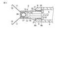
図1〜図8に基づいて本発明の第1実施形態に係る内視鏡用結紮具について説明する。図1は本実施形態に係る内視鏡用結紮具全体の説明図であり、先端部分は断面して示してある。(First embodiment)
The endoscope ligation tool according to the first embodiment of the present invention will be described with reference to FIGS. FIG. 1 is an explanatory view of the entire endoscope ligation tool according to the present embodiment, and the distal end portion is shown in cross section.
本内視鏡用結紮具は、装置本体1とクリップ2を備え、クリップ2は装置本体1に対して着脱自在なものである。クリップ2は、装置本体1に装着された状態で後述するスライダー7によって開閉操作され、体腔内で生体組織を結紮するようになっている。 This endoscope ligation tool includes an apparatus main body 1 and a
次に、装置本体1とクリップ2を具体的に説明する。まず、図1に示すように、装置本体1は可撓性のシース4を備える。シース4は、密に巻いたコイルによって形成されている。シース4は、図示しない、たとえば内視鏡のチャンネルを通じて体腔内に挿入されるものである。シース4内には操作ワイヤー5が進退可能に挿通されている。シース4の基端には操作部本体6を備えた操作部が接続されている。操作部の操作部本体6には前後方向へ摺動自在な操作用スライダー7が取り付けられていて、スライダー7は上記操作ワイヤー5の基端につながり、操作ワイヤー5を進退操作するようになっている(操作手段)。また、図1に示すように、操作部本体6の基端部分にはスライダー7を操作する手の指を掛ける指掛け部6aが形成されている。 Next, the apparatus main body 1 and the
図1に示すように、上記シース4の先端にはパイプ状の環状部材からなるストッパー(部)8が溶接などにより固定的に取り付けられている。このストッパー8の外径は上記シース4の外径と同一であり、また、ストッパー8の内径は上記シース4の内径よりも小さい。そして、ストッパー8の内面部分は全周にわたりシース4の内面よりも内方へ突き出して小径部としてのフランジ9を形成している。 As shown in FIG. 1, a stopper (part) 8 made of a pipe-like annular member is fixedly attached to the distal end of the
上記ストッパー8はその先端によって第1のストッパー8aを形成し、第1のストッパー8aは後述するように拡開した羽根部21の後端に当接するようになっている。また、上記ストッパー8の内端は第2のストッパー8bを形成し、この第2のストッパー8bは後述するように上記押さえ部材13の大径部22の先端に当接するようになっている。 The
上記操作ワイヤー5の先端には上記クリップ2を連結する接続手段としての接続部材10が接続されている。この接続部材10は操作ワイヤー5を前後へ移動する操作によりシース4内を前後に移動する。 A connecting
次に、上記クリップ2の構成について説明する。図1に示すように、クリップ2は、例えばステンレスの帯材の中央部を折り曲げることでV字状に形作られ、折曲げ中央部に形成された半円弧状の係止部から前方へ延びる2つのアーム状のクリップ爪(脚)部材11を形成している。この両方のクリップ爪部材11の先端は互いに向き合うように内側へ折り曲げられ、鈎状の爪12を形成している。また、クリップ2は上記接続部材10に外設されることによりその接続部材10を内包するパイプ状の押さえ部材13を備える。この押さえ部材13はパイプ状(円筒状)に形成されていて、接続部材10と一緒に進退自在であり、かつ、上記一対のクリップ爪部材11を引き込み可能なものとなっている。 Next, the configuration of the
上記接続部材10の先端側部分は片側を切除した形の半円状部15を形成しており、この半円状部15の平面部16には、ティアドロップ型の突起17が垂直に突き出して設けられている。この突起17には上記クリップ2の基部に形成される輪状の係止部を係着するようになっている。 The distal end portion of the
また、図1に示すように、上記接続部材10における、半円状部15よりも基端側部分は全周にわたり外径が同一の円柱状部19となっている。この円柱状部19よりも手元側部分は上記円柱状部19よりも外径が小さい円柱状の比較的細長い小径部20となっている。この小径部20の基端には上述した操作ワイヤー5の先端が接着材や溶接などの接続手段により固定的に連結されている。上記押さえ部材13は、上記接続部材10に外設しており、その接続部材10を内包するとともに、接続部材10を包囲する。そして、この状態で、シース4内に収納され、シース4に装着される。押さえ部材13は、上記接続部材10と上記シース4に対しての進退自在なものであり、上記クリップ爪部材11を内部に引き込み可能なものである。 Moreover, as shown in FIG. 1, the base end side part rather than the semicircle-
図2に示すように、上記押さえ部材13はその長手方向の中央部付近に、複数の羽根部21を設けている。羽根部21はその先端側部分のみが押さえ部材13につながっている。各羽根部21は、パイプ状の押さえ部材13との接続部分を支点とし、それ自身の弾性を利用して押さえ部材13内に畳んで収納が可能なものとなっている。 As shown in FIG. 2, the
押さえ部材13の基端部外周は、シース4の内径よりも小さく、内周が上記シース4の先端にあるストッパー8の内径よりも大きい大径部22を形成する。大径部22を形成することにより、押さえ部材13の基端部分には接続部材10の円柱状部19の外径よりも小さい内径のフランジ状の係止部23を形成する。 The outer periphery of the proximal end portion of the
また、羽根部21を除いた押さえ部材13の外径はシース4の内径より小さく形成されており、このため、羽根部21を畳んだ状態で押さえ部材13全体をシース4内に収納可能である。逆に、羽根部21が開いた状態ではその羽根部21の後端がシース4及びストッパー8の内径よりも大きくなって、ストッパー8の第1のストッパー8aと当接して係止する状態になる。押さえ部材13を前進させると、その押さえ部材13の大径部22の先端がストッパー8の第2のストッパー8bに当たり、押さえ部材13は、それ以上、前進できなくなる。 Further, the outer diameter of the pressing
そして、上記押さえ部材13が上記シース4の先端を構成するストッパー8から突き出したとき、上記羽根部21が拡開し、手元側へ引き込もうとしても拡開した羽根部21が上記ストッパー8の第1のストッパー8aと当接する。これによって、上記押さえ部材13が上記シース4内に引き込まれることを阻止する手段を構成している。また、上記押さえ部材13が上記ストッパー8の先端から突き出たとき、上記押さえ部材13に設けられた外径の大きい大径部22の先端が第2のストッパー8bに当接し、これによって、上記押さえ部材13の先端側への移動を防止する手段を構成している。 When the
さらに、図1及び図2に示すように、上記押さえ部材13の大径部22よりも先端側に位置する直近の近傍部位には強度を弱くした脆弱部25が形成されている。この脆弱部25は例えば、押さえ部材13の肉厚を薄くしたり、押さえ部材13にスリットを入れたりすることなどの方法で形成される。 Further, as shown in FIGS. 1 and 2, a weakened
図2に示すように、押さえ部材13の先端には、先端開口領域に突き出した複数のブリッジ部26が設けられている。ブリッジ部26がない非閉塞部分は、上記クリップ爪部材11が摺動可能な寸法に開口する。上記各ブリッジ部26は、例えば、図2に示すように、押さえ部材13の先端から押さえ部材13の内側へ向けて突き出して押さえ部材13と一体に形成されている。 As shown in FIG. 2, a plurality of
なお、ブリッジ部26としては、図3に示すように、押さえ部材13の先端に前方に向けて突設した片27を、押さえ部材13の内側へ向けて折り曲げ変形することで作るようにしてもよい。 As shown in FIG. 3, the
次に、本実施形態の内視鏡用結紮具の使用方法について図4〜8を参照しながら説明する。
まず、図4に示すように、シース4の先端部内に完全に収納した状態でクリップ2を装着する。このように装着した状態で、クリップ2の羽根部21は、シース4の内周面に当たり押し込まれ、その弾性範囲で畳まれている。また、上記クリップ爪部材11も同じくシース4の内周面に当たり押し込まれ、その弾性範囲で閉じている。Next, a method of using the endoscope ligation tool of the present embodiment will be described with reference to FIGS.
First, as shown in FIG. 4, the
このようなクリップ2を収納した状態で、シース4を、図示しない、たとえば内視鏡のチャンネル挿入口(鉗子栓)からそのチャンネル内に挿入し、シース4の先端部分を体腔内に導く。内視鏡とは別の器具を用いて体腔内にシース4を導入するようにしてもよい。 In a state where the
そして、体腔内でシース4の先端部が内視鏡から突き出したら操作部本体6に対してスライダー7を先端側へ押して前進させて操作ワイヤー5を押し込む。すると、図5に示すように、上記クリップ2の先端部分が、シース4のストッパー8から外へ突き出る。このとき、押さえ部材13の基端部分に位置する大径部22は、シース4の先端に設けたストッパー8の内径より大きいため、そのストッパー8のフランジ9の部分に突き当たり、それ以上、クリップ2の前進移動が阻止され、クリップ2の全体がシース4の先端開口から突き抜けることはない。 And if the front-end | tip part of the
また、ストッパー8の長さに対して、大径部22の先端から羽根部21の後端までの長さは若干長く作られているので、押さえ部材13の大径部22がストッパー8の後端に位置する第2のストッパー8bに突き当たった図5に示す時点で、羽根部21の全体がシース4及びストッパー8から外へ出て解放される。そして、羽根部21はそれ自身の弾性による拡張力により、図5に示すように拡開する。また、羽根部21が拡開することで、羽根部21の後端がストッパー8の先端にある第1のストッパー8aに当たり得るようになり、押さえ部材13は手元側への移動が阻止される。このような移動阻止手段による機能によって、これ以後、押さえ部材13はシース4内に引き込むことができなくなる。 In addition, since the length from the tip of the
さらに、押さえ部材13の大径部22がストッパー8の第2のストッパー8bに突き当るようになっているため、押さえ部材13の先端側への移動も阻止されるようになる。この移動阻止手段による機能によって、これ以後、クリップ2の押さえ部材13は、それ以上、シース4から突き出ることができなくなる。
このようにして、クリップ2の押さえ部材13の移動を阻止する固定手段はその機能を奏する。この押さえ部材13の固定状態で、クリップ爪部材11は、既に操作手段の接続部材10と共にブリッジ部26を越えて突き出るように前進させられており、また、クリップ爪部材11はその内側に位置するブリッジ部26により拡げられ、クリップ爪部材11は図5に示すように開いた状態となる。Furthermore, since the large-
Thus, the fixing means for preventing the movement of the pressing
次に、このようにクリップ爪部材11を開いた状態のまま、内視鏡による観察下で、シース4を内視鏡に対して押し込み、クリップ爪部材11の先端を組織Aに押し付ける。 Next, the
さらに、操作部本体6に対してスライダー7を引くことにより、操作ワイヤー5を介して接続部材10を手前に引き、クリップ爪部材11を押さえ部材13内に引き込む。すると、図6に示すように、押さえ部材13内にクリップ爪部材11を深く引き込むことになり、クリップ爪部材11は、押さえ部材13の内面により閉じ込められ、クリップ爪部材11により組織Aを把持し、結紮状態になる。 Further, by pulling the slider 7 with respect to the operation portion
この作業において、組織Aを適切な状態で結紮することが出来なかった場合、再度、操作部本体6に対してスライダー7を先端側へ移動することで、クリップ爪部材11を開き、図5で示す状態に戻す。そして、上述したと同様、スライダー7を引くことで、クリップ爪部材11を閉じ、組織Aを再度把持しようとする。この操作を図6で示す適切な把持状態になるまで繰り返す。 In this work, when the tissue A cannot be ligated in an appropriate state, the
クリップ爪部材11が適切な状態で組織Aを把持したら、スライダー7を強く手元側へ引く。すると、図7に示すように、接続部材10における半円状部15の破断可能部分が破断する。この接続部材10の破断可能部分の破断を的確に行わせるために、上記半円状部15に径を細めた強度的に弱い部分を設けても良い。 When the
また、破断した接続部材10に残った円柱状部19の基端部分は、図8に示すように押さえ部材13の係止部23に引っ掛かる。この係止した状態からスライダー7をさらに強く引くと、今度は、押さえ部材13の強度的に弱い脆弱部25の部分が破断し、クリップ2が装置本体1のシース4から離脱し、組織Aを把捉した状態の上記クリップ2を上記シース4から解放する。 Further, the base end portion of the
このように、クリップ2を解放する手段が作用した後、図8に示すように、シース4から離脱したクリップ2のクリップ爪部材11は押さえ部材13により絞り込まれ、押さえ部材13の内面との摩擦抵抗により閉じた状態に維持される。したがって、図8に示すように、クリップ2は組織Aを結紮した閉状態のまま、体腔内に留置される。 Thus, after the means for releasing the
以上の如く、本実施形態では、シース4内にクリップ2を収納した状態で、たとえば内視鏡のチャンネルなどを通じて体腔内に挿入し、その後、クリップ2をシース4の先端から突き出すようにしたので、内視鏡などの誘導器具を損傷させる虞が無く、また、内視鏡などの誘導器具のチャンネルなどに引っ掛かることなく、軽く挿入することが可能になる。 As described above, in the present embodiment, the
また、押さえ部材13の大径部22と羽根部21の係止手段により、クリップ2とシース4とが固定され、スライダー7の前後動操作により、クリップ2の開閉を繰り返し行い得るようになる。クリップ2の開閉を何回も確実に行うことが可能なので、組織Aを適切な結紮状態になるまで操作を繰り返すころができる。スライダー7を押す動作がクリップ2の突き出し動作とクリップ2の開動作となり、スライダー7の引き動作がクリップ2の閉じ動作とクリップの離脱になる操作部のスライダー7の動き方向と先端の動き方向が一致しており、このため、直感的な操作が可能である。 Further, the
また、クリップ2のクリップ爪部材11を強制的に開けるように押さえ管としての押さえ部材13の先端にブリッジ部26を設けるようにしたので、クリップ爪部材11の開閉操作も確実に行うことが可能になった。 Further, since the
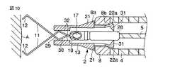
(第2実施形態)
図9〜図13に基づいて本発明の第2実施形態に係る内視鏡用結紮具について説明する。本実施形態は上述した第1実施形態とは次の点で相違する。(Second Embodiment)
An endoscope ligation tool according to a second embodiment of the present invention will be described with reference to FIGS. This embodiment is different from the above-described first embodiment in the following points.
すなわち、図9に示すように、操作ワイヤー5の遠位端にはワイヤー大径部28が設けられている。ワイヤー大径部28は、操作ワイヤー5よりも大きな径の管状部材またはワイヤー部材を取り付けて構成され、上記接続部材10よりも手元側に位置する。このワイヤー大径部28は、たとえば操作ワイヤー5と一体の物あるいは別部材のものを上記接続部材10に接着、機械的接続や溶接などにより連結してなる。 That is, as shown in FIG. 9, the wire large-
本実施形態のクリップ2は、2つのクリップ爪部材11を、たとえばステンレス製の帯状部材の中央部を少なくとも2回クロスさせて折り曲げた複数のクロス部29を備える。2つのクロス部29の間には少なくとも1つの山部30が形成されている。クリップ2は上記接続部材10を内包するパイプ状の押さえ部材13を備え、この押さえ部材13の長手方向手元側端にはその押さえ部材13の外周部分よりも大きな径で外へ広がり得る大径部22aが形成されている。大径部22aはその先端側部分のみが押さえ部材13につながっている。また、大径部22aの手元側端には内方へ突き出す少なくとも1つの突起部31が設けられている。そして、大径部22aは接続部分を支点とし、押さえ部材13の接続部分またはそれ自身の弾性を利用して拡開し得る。 The
また、図9に示すように、押さえ部材13の先端部分の内側には内方へ突き出たフランジ状の小径部32が形成されている。この小径部32は段差状に形成されているが、スロープ状など他の形状によって形成したものでもよい。上記クロス部29の山部30同士が押さえ部材13の径方向に離間する距離は、少なくとも押さえ部材13の小径部32の径よりも大きいが、その小径部32以外の部分の内径よりも大きくても小さくてもよい。 As shown in FIG. 9, a flange-shaped small-
次に、本実施形態の内視鏡用結紮具の使用方法について図9〜図13を参照しながら説明する。上述した第1実施形態と同様な手順で使用されるが、以下のような相違がある。 Next, a method for using the endoscope ligation tool of the present embodiment will be described with reference to FIGS. The same procedure as in the first embodiment described above is used, but there are the following differences.
まず、図9に示すように、クリップ2をシース4の先端部内に完全に収納した状態にする。このクリップ収納状態では、押さえ部材13における突起部31の先端が操作ワイヤー5のワイヤー大径部28の外周面に当たり、突起部31はその弾性範囲内で押し広げられている。 First, as shown in FIG. 9, the
このようなクリップ収納状態で本装置1のシース4を内視鏡のチャンネルに挿入し、シース4の先端部の部分を体腔内へ導く。そして、内視鏡観察によりシース4の先端の部分が体腔内で突き出したことを確認したら操作部本体6に対してスライダー7を先端側へ押して前進し、操作ワイヤー5を押し込む。すると、図10に示すように、クリップ2のクリップ爪部材11の部分が、シース4のストッパー8から外へ突き出る。このとき、押さえ部材13の手元側にある大径部22aはシース4のストッパー8の内径よりも大きく広がっているため、図10に示すように、その大径部22aがストッパー8の第2のストッパー8bに突き当たり、クリップ2はそれ以上に前進できない。 With the clip stored in such a state, the
押さえ部材13がシース4の先端部分に固定された状態で、操作部のスライダー7を押し込み、操作ワイヤー5を介して接続部材10を押し進めることにより、図10に示すようにクリップ爪部材11を押さえ部材13の先端から突き出す。すると、押さえ部材13の小径部32により、クロス部29の山部30が押し潰され、クリップ爪部材11および爪12は開いた状態になる。この爪12が開いた状態からシース4を内視鏡に対して押し込むことで、病変組織に爪12の先端を押し付ける。 In a state where the pressing
次に、操作部のスライダー7を手前側に引き、操作ワイヤー5および接続部材10を介してクリップ爪部材11を押さえ部材13に引き込むと、図11に示すように、クリップ爪部材11は押さえ部材13の内面により閉じ、病変組織Aを把持する結紮状態になる。 Next, when the slider 7 of the operation portion is pulled to the near side and the
この操作によって、組織Aを適切な状態で結紮できなかった場合は、再度、操作部本体6に対してスライダー7を先端側へ移動して、クリップ爪部材11を再度開き、図10に示す開状態に戻す。そして、再び上述したと同様に操作し、スライダー7を手前側に牽引することで、クリップ爪部材11を閉じ、組織Aを再度把持する一連の操作を行う。 When the tissue A cannot be ligated in an appropriate state by this operation, the slider 7 is again moved to the distal end side with respect to the operation portion
このような一連の操作を図11に示すような適切な把持状態になるまで繰り返す。適切な状態で組織Aを把持できたら今度はスライダー7をより強く手元側へ牽引する。すると、図12に示すように接続部材10における半円状部15が破断する。このとき、ワイヤー大径部28を備えた操作ワイヤー5の部分はシース4内に引き込まれ、また、ワイヤー大径部28で押し広げられていた押さえ部材13の大径部22aが自身の弾性により内側に縮む。そして、大径部22aは押さえ部材13と同じ径になり、クリップ2は図13に示すようにシース4より解き放されて離脱する。 Such a series of operations is repeated until an appropriate gripping state as shown in FIG. 11 is obtained. If the tissue A can be grasped in an appropriate state, the slider 7 is pulled more strongly toward the hand side. Then, as shown in FIG. 12, the
そして、本実施形態のクリップ開閉機構は、クリップ2の開閉を繰り返しても、クリップ2の材質に関係なく、クリップ2の開き幅の劣化減少を抑えられる。このことからクリップ2の開閉を恒久的に繰り返すことができる。 The clip opening / closing mechanism of the present embodiment can suppress a decrease in the opening width of the
なお、開き直し式クリップでは繰り返し開閉を繰り返すと、クリップが塑性変形して、クリップの開き幅が減少してしまうという課題があったが、本実施形態ではこの課題を解決できる。さらに開き直し式クリップは押さえ部材とシースとの固定が必須となっており、そのためにクリップの分離箇所に塑性変形を用いると、繰り返し開閉が確実に行えないという課題があったが、本実施形態ではこの課題も解決できる。 In the reopening type clip, when the opening and closing are repeated, there is a problem that the clip is plastically deformed and the opening width of the clip is reduced, but this embodiment can solve this problem. Furthermore, the re-opening type clip requires the fixing of the holding member and the sheath. For this reason, if plastic deformation is used at the separation part of the clip, there is a problem that it cannot be reliably opened and closed repeatedly. Then this problem can be solved.
以上の如く、本実施形態では、クリップ2をシース4から分離する解放手段の機構の変形している部分が弾性的に元に戻るため、確実に分離することができる。また、接続部材10の破断以外に大きな操作力を必要としないため、軽い力での操作が可能である。 As described above, in this embodiment, since the deformed portion of the mechanism of the release means that separates the
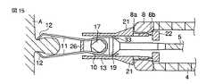
(第3実施形態)
図14及び図15に基づいて本発明の第3実施形態に係る内視鏡用結紮具について説明する。本実施形態は上述した第1実施形態のものとは次の点で相違する。(Third embodiment)
An endoscope ligation tool according to a third embodiment of the present invention will be described based on FIGS. 14 and 15. This embodiment is different from that of the first embodiment described above in the following points.
すなわち、図14に示すように、押さえ部材13の長手方向中央付近の内側にその押さえ部材13の中心軸方向に向けて突き出る板バネ33を設けたものである。この板バネ33はたとえば押さえ部材13と一体の物、あるいは別部材のものを接着、機械的接続または溶接などで押さえ部材13に取り付けたものである。この板バネ33は、通常、接続部材10または操作ワイヤー5の部分に接触しており、接続部材10または操作ワイヤー5に対して先端方向へ向く弾性力をかけるような寸法・設定になっている。この板バネ33は上記クリップ爪部材11を上記押さえ部材13に対して前進させる手段を構成する。 That is, as shown in FIG. 14, a
次に、本実施形態の内視鏡用結紮具の使用方法について図14及び図15を参照しながら説明する。これは、上述した第1実施形態と略同様な手順で使用されるが、以下のような相違がある。 Next, a method for using the endoscope ligation tool of the present embodiment will be described with reference to FIGS. This is used in substantially the same procedure as in the first embodiment described above, with the following differences.
図14に示すように、スライダー7に操作力が加わっていないとき、接続部材10は押さえ部材13の先端側に位置しており、このため、クリップ爪部材11は開き、板バネ33の弾性力は解放されている。 As shown in FIG. 14, when no operating force is applied to the slider 7, the connecting
次に、図15に示すように、スライダー7を手前側に引き、操作ワイヤー5を介して、接続部材10を手元側に引くと、板バネ33は接続部材10に係止して手前側に曲げられ、接続部材10を先端側へ押し出すように弾性力が働く。一方、クリップ爪部材11は閉じる。 Next, as shown in FIG. 15, when the slider 7 is pulled to the near side and the connecting
このとき、適切な状態で組織Aを結紮できなかった場合、スライダー7にかけていた手前側に引く力を取り除く。すると、板バネ33の弾性力によって接続部材10が先端側へ戻され、クリップ爪部材11が再び開き、図14に示す開いた状態に復帰する。
そして、上述したと同様に操作し、スライダー7を引くことで、クリップ爪部材11を閉じ、組織Aを再度把持する。At this time, when the tissue A cannot be ligated in an appropriate state, the pulling force on the near side applied to the slider 7 is removed. Then, the
Then, by operating in the same manner as described above and pulling the slider 7, the
本実施形態ではクリップ2の開動作において、操作ワイヤー5を介さず、板バネ33が接続部材10を先端側へ直接押すので、操作ワイヤー5が弛んで接続部材10を操作できなくなることがなく、クリップ爪部材11を確実に開閉できるようになる。 In this embodiment, in the opening operation of the
また、スライダー7を引くと、クリップ2が閉まり、スライダー7を離すと、クリップ2が閉まる。したがって、より簡単な構成のクリップ2の開閉機構を実現できる。 When the slider 7 is pulled, the
一般に、操作ワイヤー5を介してスライダー7の動きをクリップ2に伝えてクリップ2を開閉する場合、スライダー7を押したとき、操作ワイヤー5が撓み、スライダー7の動きを先端のクリップ2に確実に伝えられないという課題があったが、本実施形態ではそのような課題を解決できる。 In general, when the movement of the slider 7 is transmitted to the
なお、本実施形態の構成では第1実施形態に適応した例で説明しているが、第2実施例についても同じように適応が可能である。 In the configuration of the present embodiment, an example adapted to the first embodiment has been described. However, the second embodiment can be similarly adapted.
(第4実施形態)
図16及び図17に基づいて本発明の第4実施形態に係る内視鏡用結紮具について説明する。本実施形態は上述した第3実施形態のものとは次の点で相違する。(Fourth embodiment)
An endoscope ligation tool according to a fourth embodiment of the present invention will be described with reference to FIGS. 16 and 17. This embodiment differs from that of the third embodiment described above in the following points.
本実施形態では図16に示すようにバネ部材としてコイルバネ34を採用しており、このコイルバネ34は押さえ部材13内に挿入されるとともに、接続部材10の円柱状部19と係止部23との間に設置されている。このコイルバネ34の先端は接続部材10の円柱状部19に当たり、コイルバネ34の後端は係止部23に接触し、その弾性反発力が接続部材10に対して先端方向への向きに加わるように寸法等が設定されている。 In the present embodiment, as shown in FIG. 16, a
したがって、上述した第3実施形態と同様に使用する際、スライダー7による操作力を加えていないとき、接続部材10は図16に示すように押さえ部材13の先端側に位置しており、このため、クリップ爪部材11は開き、コイルバネ34の弾性力は解放された状態にある。 Therefore, when used in the same manner as in the third embodiment described above, when no operating force is applied by the slider 7, the connecting
次に、図17に示すように、スライダー7を手元側に引き、操作ワイヤー5を介して、接続部材10を引くと、コイルバネ34は接続部材10と係止部23により縮められ、その弾性力が接続部材10を先端側へ押し出すように働く。一方、クリップ爪部材11は押さえ部材13内に引き込まれ、クリップ爪部材11が閉じ、組織Aを結紮する。 Next, as shown in FIG. 17, when the slider 7 is pulled toward the hand side and the connecting
このとき、組織Aを適切な状態で結紮できなかった場合、スライダー7にかけていた手前側に引く力を取り除く。すると、コイルバネ34の弾性力により、接続部材10が先端側へ移動し、クリップ爪部材11を開き、図16に示す開状態に戻る。 At this time, if the tissue A cannot be ligated in an appropriate state, the pulling force on the near side applied to the slider 7 is removed. Then, due to the elastic force of the
再び、上述したと同様の操作を行って、スライダー7を引くことで、クリップ爪部材11を閉じ、組織Aを再度把持する。このような操作を、組織Aを適切な状態で結紮できるまで繰り返す。 Again, the same operation as described above is performed and the slider 7 is pulled to close the
本実施形態によれば、上述した第3実施形態の効果に加え、弾性部としてコイルバネ34を用いるので、上述した第3実施形態よりも大きな弾性力を確実に得ることができ、長手方向における先端側に強い力を加えることにより、クリップ爪部材11の確実な開動作が可能となる。 According to the present embodiment, since the
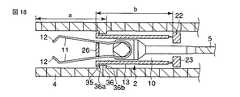
(第5実施形態)
図18乃至図23に基づいて本発明の第5実施形態に係る内視鏡用結紮具について説明する。本実施形態は上述した第1実施形態のものとは次の点で相違する。(Fifth embodiment)
An endoscope ligation tool according to a fifth embodiment of the present invention will be described with reference to FIGS. This embodiment is different from that of the first embodiment described above in the following points.
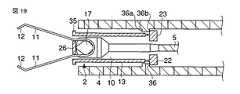
すなわち、押さえ部材13の真ん中付近に設けられていた羽根部21の代わりに、その押さえ部材13の先端に外方へ張り出すフランジ状の係止部35を形成するものである。また、シース4の先端に設けられていたストッパー部8の代わりにシース4の先端から押さえ部材13の長さ程度離れた位置に外方へ張り出すフランジ状の小径部36をシース4に設けたものである。この小径部36の先端により係止部35に当接する第1のストッパー36aを形成し、小径部36の後端により大径部22の先端が当接する第2のストッパー36bを形成する。その他の構成は、上述した第1実施形態と同様である。 That is, instead of the
上記係止部35の外径はシース4の内径より小さく、小径部36の内径よりも大きい。小径部36の内径は押さえ部材13の係止部35及び大径部22を除いた部分の外径より大きい寸法設定となっている。また、小径部36はシース4の一部を外周から潰すことで構成したり、別部品を接続したりして構成できる。 The outer diameter of the locking
図18に示すように、小径部36の手元端からシース4の先端までの長さ「a」は押さえ部材13の大径部22の第1のストッパー36aから押さえ部材13の先端までの長さ「b」に対して同一の長さか若干短めの長さとなっている。 As shown in FIG. 18, the length “a” from the proximal end of the
次に、本実施形態の内視鏡用結紮具の使用方法について説明する。上述した第1実施形態と同様な手順で使用されるが、以下のような相違がある。 Next, a method for using the endoscope ligation tool of the present embodiment will be described. The same procedure as in the first embodiment described above is used, but there are the following differences.
係止部35がシース4における小径部36の第1のストッパー36aに突き当たるまでスライダー7を手前に引くことで、図18に示すようにクリップ2の全体をシース4内に収納する。このクリップ収納状態で内視鏡に挿入し、シース4の先端を内視鏡から体腔内に突き出す。そして、スライダー7を先端側に押すと、クリップ2の全体がシース4に対して先端側へ移動し、図19に示すように、押さえ部材13の大径部22の先端部分がシース4の小径部36における第2のストッパー36bに突き当たる。 The
スライダー7を先端側へ更に押すと、クリップ爪部材11が押さえ部材13から先端側へ押し出され、クリップ爪部材11は、押さえ部材13のブリッジ部26により強制的に開かれる(図19を参照)。 When the slider 7 is further pushed to the tip side, the
内視鏡に対して、シース4を押し込むことにより、クリップ2を患部(出血部)に押し付け、その後、スライダー7を手元側に引き、クリップ2をシース4内に引き込む。これにより、クリップ爪部材11がシース4内に引き込まれることで、クリップ爪部材11は患部の組織Aを仮結紮した状態となる(図20を参照)。 By pushing the
この仮結紮状態で、出血が十分止まっていれば、本結紮に移るが、患部から外れて結紮してしまった場合には出血が収まらない。このため、再結紮を行う。これは、スライダー7を先端側に押すことで、上述と同じ動作により、クリップ爪部材11を開かせ、再度、同様な作業により患部の結紮を行うものである。 If the bleeding has stopped sufficiently in this temporary ligation state, the ligation is transferred to the main ligation. For this reason, religation is performed. In this case, the
そして、仮結紮がうまくいった場合は、スライダー7をさらに手前に引くことで、クリップ爪部材11を押さえ部材内に引き込み、本結紮を行う(図21を参照)。この後の作用は上述した第1実施形態のものと同様である。 If the temporary ligation is successful, the slider 7 is pulled further forward to pull the
本実施形態では上述した第1実施形態と同一の効果を奏する。さらに以下のような効果も奏する。つまり、可動の羽根部は可動とするが故に、シース内に長期に羽根部を折りたたんだ状態にしておくと、羽根部の持つ弾性力が失われ、シース先端に引っかかるように羽根部が広がらなくなる虞があるが、本実施形態では固定の係止部35としたことにより、シース4と押さえ部材13を確実に固定可能である。 In the present embodiment, the same effects as those of the first embodiment described above can be obtained. In addition, the following effects are also achieved. In other words, since the movable blade portion is movable, if the blade portion is folded in the sheath for a long time, the elastic force of the blade portion is lost and the blade portion does not spread so as to be caught by the sheath tip. Although there is a possibility, the
また、本実施形態での仮結紮は、クリップ爪部材11をシース4内に引き込むことで行い、本結紮はクリップ爪部材11を押さえ部材13内に引き込むことで行うという、独立した作用によって行われる。また、クリップ2は、シース4から切り離された後も患部を結紮した状態を保持しなければならず、クリップ爪部材11と押さえ部材11の間にある程度の摩擦力を必要とする。この摩擦力は、再結紮(仮結紮後に再度クリップ爪部材11を開くこと)の際に、クリップ爪部材11を押さえ部材13から押し出す際の妨げになってしまう可能性があるが、本実施形態では、仮結紮ではクリップ爪部材11が押さえ部材13に入らないため、確実にクリップ爪部材11の開き動作が行える。 Further, the temporary ligation in the present embodiment is performed by pulling the
本発明は前述した実施形態のものに限定されるものではなく、他の形態にも適用が可能である。 The present invention is not limited to the embodiment described above, and can be applied to other forms.
1…装置本体
2…クリップ
4…シース
5…操作ワイヤー
7…スライダー
8…ストッパー
8a…第1のストッパー
8b…第2のストッパー
10…接続部材
11…クリップ爪部材
13…押さえ部材
21…羽根部
25…脆弱部DESCRIPTION OF SYMBOLS 1 ... Apparatus
Claims (34)
Translated fromJapanese生体組織を結紮する開閉自在なクリップ爪部材及びこのクリップ爪部材に被嵌する押さえ部材を有したクリップと、
シースと、
上記シース内にあって進退自在な操作ワイヤーと、
上記操作ワイヤーの遠位側に設けられ、上記クリップ爪部材に接続可能な接続手段と、
上記操作ワイヤーを進退操作する操作部と、
上記シース及び上記押さえ部材の少なくとも一方に設けられ、上記シースと上記押さえ部材とを互いに係止させることにより、上記シースの先端から上記クリップ爪部材が生体組織を結紮可能な状態に突き出された位置において、上記シースに対する上記押さえ部材の前進移動を規制する第1の移動阻止手段と、
上記クリップ爪部材で上記生体組織を結紮するとき、上記シースに対する上記押さえ部材の後退移動を規制する第2の移動阻止手段と、
上記シースに対して上記操作ワイヤーを移動することで、上記第1の移動阻止手段が変形されて、生体組織を把捉した状態の上記クリップを上記シースから解き放す解放手段と、
を備えたことを特徴とする結紮装置。In the ligation apparatus in which the clip ligating the biological tissue in the body cavity is placed in the body cavity,
A clip claw member that can be freely opened and closed to ligate a living tissue, and a clip having a pressing member that fits over the clip claw member;
A sheath,
An operation wire that is movable in and out of the sheath, and
A connection means provided on the distal side of the operation wire and connectable to the clip claw member;
An operation unit for advancing and retracting the operation wire;
Provided on at least one of the sheath and the pressing member, by locking together the said sheath and the pressing member, a position where the clip claw memberis projecting a living tissue ligating ready from the distal end of the sheath a first movement preventing means for restricting the forward movement of the pressing memberOite, relative to the sheath,
A second movement preventing means for restricting the backward movement of the pressing member relative to the sheath when ligating the living tissue with the clip claw member;
By moving the operation wire withrespect to the sheath,the first movement preventing means is deformed, and release means for releasing the clip in a state of graspinga living tissue from the sheath;
A ligation apparatus characterized by comprising:
上記係止部は、上記押さえ部材に設けられ、上記フランジの内径よりも大きい径を含む大径部であることを特徴とするもの。The ligation apparatus according to claim 3, wherein the stopper is a flange provided on the sheath so as to protrude inward of the sheath,
The locking portion is a large-diameter portion provided on the pressing member and including a diameter larger than the inner diameter of the flange.
Priority Applications (10)
| Application Number | Priority Date | Filing Date | Title |
|---|---|---|---|
| JP2005232253AJP4758173B2 (en) | 2004-12-24 | 2005-08-10 | Ligation device |
| CN2009102211275ACN101695452B (en) | 2004-12-24 | 2005-12-22 | Ligation apparatus |
| EP11000749.9AEP2327364B1 (en) | 2004-12-24 | 2005-12-22 | Ligation apparatus |
| CN2005800444317ACN101087564B (en) | 2004-12-24 | 2005-12-22 | Ligation device |
| EP05820086.6AEP1829489B1 (en) | 2004-12-24 | 2005-12-22 | Ligation device |
| US11/722,490US8551119B2 (en) | 2004-12-24 | 2005-12-22 | Ligation apparatus |
| KR1020077014162AKR100918723B1 (en) | 2004-12-24 | 2005-12-22 | Ligation device |
| KR1020097005124AKR101038134B1 (en) | 2004-12-24 | 2005-12-22 | Ligation device |
| PCT/JP2005/023652WO2006068242A1 (en) | 2004-12-24 | 2005-12-22 | Ligation device |
| US13/089,641US8690899B2 (en) | 2004-12-24 | 2011-04-19 | Ligation apparatus |
Applications Claiming Priority (3)
| Application Number | Priority Date | Filing Date | Title |
|---|---|---|---|
| JP2004374333 | 2004-12-24 | ||
| JP2004374333 | 2004-12-24 | ||
| JP2005232253AJP4758173B2 (en) | 2004-12-24 | 2005-08-10 | Ligation device |
Related Child Applications (1)
| Application Number | Title | Priority Date | Filing Date |
|---|---|---|---|
| JP2008296824ADivisionJP4870139B2 (en) | 2004-12-24 | 2008-11-20 | Ligation device |
Publications (3)
| Publication Number | Publication Date |
|---|---|
| JP2006198388A JP2006198388A (en) | 2006-08-03 |
| JP2006198388A5 JP2006198388A5 (en) | 2009-01-08 |
| JP4758173B2true JP4758173B2 (en) | 2011-08-24 |
Family
ID=36601839
Family Applications (1)
| Application Number | Title | Priority Date | Filing Date |
|---|---|---|---|
| JP2005232253AExpired - Fee RelatedJP4758173B2 (en) | 2004-12-24 | 2005-08-10 | Ligation device |
Country Status (6)
| Country | Link |
|---|---|
| US (2) | US8551119B2 (en) |
| EP (2) | EP1829489B1 (en) |
| JP (1) | JP4758173B2 (en) |
| KR (2) | KR101038134B1 (en) |
| CN (1) | CN101695452B (en) |
| WO (1) | WO2006068242A1 (en) |
Families Citing this family (233)
| Publication number | Priority date | Publication date | Assignee | Title |
|---|---|---|---|---|
| US7094245B2 (en)* | 2001-10-05 | 2006-08-22 | Scimed Life Systems, Inc. | Device and method for through the scope endoscopic hemostatic clipping |
| CA2809110A1 (en) | 2004-10-08 | 2006-04-20 | Tyco Healthcare Group Lp | Apparatus for applying surgical clips |
| EP2641548B1 (en) | 2004-10-08 | 2015-08-19 | Covidien LP | Endoscopic surgical clip applier |
| US9763668B2 (en) | 2004-10-08 | 2017-09-19 | Covidien Lp | Endoscopic surgical clip applier |
| US8409222B2 (en) | 2004-10-08 | 2013-04-02 | Covidien Lp | Endoscopic surgical clip applier |
| JP4758173B2 (en)* | 2004-12-24 | 2011-08-24 | オリンパス株式会社 | Ligation device |
| JP5175833B2 (en)* | 2006-03-10 | 2013-04-03 | クック メディカル テクノロジーズ エルエルシー | Medical device capable of drawing target tissue into clip arm housing chamber |
| EP2015681B1 (en) | 2006-05-03 | 2018-03-28 | Datascope Corp. | Tissue closure device |
| CA2605135C (en) | 2006-10-17 | 2014-12-30 | Tyco Healthcare Group Lp | Apparatus for applying surgical clips |
| JP4716513B2 (en)* | 2006-11-09 | 2011-07-06 | Hoya株式会社 | Endoscopic clip device |
| EP2157920B1 (en) | 2007-03-26 | 2017-09-27 | Covidien LP | Endoscopic surgical clip applier |
| CN102327136B (en) | 2007-04-11 | 2014-04-23 | 柯惠Lp公司 | Surgical clip applier |
| US8162959B2 (en)* | 2007-05-03 | 2012-04-24 | Boston Scientific Scimed, Inc. | Single stage hemostasis clipping device |
| JP2009000364A (en)* | 2007-06-22 | 2009-01-08 | Bekutoronikusu:Kk | Clip device of biotissue |
| US20090030446A1 (en)* | 2007-07-25 | 2009-01-29 | Measamer John P | Tissue Manipulator |
| JP5006753B2 (en)* | 2007-10-17 | 2012-08-22 | Hoya株式会社 | Endoscopic clip device |
| JP5371228B2 (en)* | 2007-11-08 | 2013-12-18 | オリンパス株式会社 | Endoscopic treatment tool |
| EP3061413B1 (en) | 2008-06-19 | 2022-01-19 | Boston Scientific Scimed, Inc. | Tissue clipping apparatus |
| US8652202B2 (en) | 2008-08-22 | 2014-02-18 | Edwards Lifesciences Corporation | Prosthetic heart valve and delivery apparatus |
| US20110208212A1 (en) | 2010-02-19 | 2011-08-25 | Zergiebel Earl M | Surgical clip applier |
| US8465502B2 (en) | 2008-08-25 | 2013-06-18 | Covidien Lp | Surgical clip applier and method of assembly |
| US8056565B2 (en) | 2008-08-25 | 2011-11-15 | Tyco Healthcare Group Lp | Surgical clip applier and method of assembly |
| US9358015B2 (en) | 2008-08-29 | 2016-06-07 | Covidien Lp | Endoscopic surgical clip applier with wedge plate |
| US8267944B2 (en) | 2008-08-29 | 2012-09-18 | Tyco Healthcare Group Lp | Endoscopic surgical clip applier with lock out |
| US8409223B2 (en) | 2008-08-29 | 2013-04-02 | Covidien Lp | Endoscopic surgical clip applier with clip retention |
| US8585717B2 (en) | 2008-08-29 | 2013-11-19 | Covidien Lp | Single stroke endoscopic surgical clip applier |
| JP2010119682A (en)* | 2008-11-20 | 2010-06-03 | Fujifilm Corp | Cylindrical member, and multiple clip application device |
| EP2389122B1 (en)* | 2008-12-19 | 2015-03-04 | Cook Medical Technologies LLC | Clip devices |
| US10517719B2 (en) | 2008-12-22 | 2019-12-31 | Valtech Cardio, Ltd. | Implantation of repair devices in the heart |
| JP5258663B2 (en)* | 2009-04-09 | 2013-08-07 | Hoya株式会社 | Endoscopic clip device |
| TWI516244B (en)* | 2009-04-20 | 2016-01-11 | 大塚醫療器材股份有限公司 | Delivery assembly for occlusion device using mechanical interlocking coupling mechanism |
| US9968452B2 (en) | 2009-05-04 | 2018-05-15 | Valtech Cardio, Ltd. | Annuloplasty ring delivery cathethers |
| DE102009022271A1 (en)* | 2009-05-22 | 2010-11-25 | Medi-Globe Gmbh | Application device for applying, in particular for the endoscopic application of a medical clip in or on the body of an individual |
| DE102009022692B8 (en)* | 2009-05-26 | 2013-09-12 | Joimax Gmbh | Apparatus and method for applying a medical lockable clip in a tissue area |
| US9005219B2 (en) | 2009-08-19 | 2015-04-14 | Boston Scientific Scimed, Inc. | Multifunctional core for two-piece hemostasis clip |
| EP2467069A1 (en)* | 2009-08-19 | 2012-06-27 | Boston Scientific Scimed, Inc. | Multifunctional core for two-piece hemostasis clip |
| US8449599B2 (en) | 2009-12-04 | 2013-05-28 | Edwards Lifesciences Corporation | Prosthetic valve for replacing mitral valve |
| US9186136B2 (en) | 2009-12-09 | 2015-11-17 | Covidien Lp | Surgical clip applier |
| US8545486B2 (en) | 2009-12-15 | 2013-10-01 | Covidien Lp | Surgical clip applier |
| US8491611B2 (en)* | 2009-12-18 | 2013-07-23 | DePuy Synthes Products, LLC. | Neural tissue retraction and preservation device |
| US8403945B2 (en) | 2010-02-25 | 2013-03-26 | Covidien Lp | Articulating endoscopic surgical clip applier |
| US9044240B2 (en)* | 2010-03-10 | 2015-06-02 | Boston Scientific Scimed, Inc. | Hemostasis clip |
| US8968337B2 (en) | 2010-07-28 | 2015-03-03 | Covidien Lp | Articulating clip applier |
| US8403946B2 (en) | 2010-07-28 | 2013-03-26 | Covidien Lp | Articulating clip applier cartridge |
| CN103124530B (en) | 2010-09-22 | 2016-03-30 | 富士胶片株式会社 | Apparatus for ligating and the clip unit used in this apparatus for ligating |
| US9011464B2 (en) | 2010-11-02 | 2015-04-21 | Covidien Lp | Self-centering clip and jaw |
| JP2012166003A (en)* | 2011-01-28 | 2012-09-06 | Nobuyuki Sakurazawa | Medical clip reloadable after separation and delivery system |
| US9186153B2 (en) | 2011-01-31 | 2015-11-17 | Covidien Lp | Locking cam driver and jaw assembly for clip applier |
| WO2012121439A1 (en)* | 2011-03-10 | 2012-09-13 | 주식회사 파인메딕스 | Open / close-capable clip, and open / close-capable clip manipulating tool using same |
| US9775623B2 (en) | 2011-04-29 | 2017-10-03 | Covidien Lp | Surgical clip applier including clip relief feature |
| US10154842B2 (en) | 2011-05-04 | 2018-12-18 | Boston Scientific Scimed, Inc. | Through the scope tension member release clip |
| EP3345573B1 (en) | 2011-06-23 | 2020-01-29 | Valtech Cardio, Ltd. | Closure element for use with annuloplasty structure |
| EP2755578A2 (en)* | 2011-09-15 | 2014-07-23 | Teleflex Medical Incorporated | Manual surgical ligation clip applier |
| JP5427858B2 (en)* | 2011-09-15 | 2014-02-26 | 富士フイルム株式会社 | Ligating device and endoscope system |
| WO2013067662A1 (en)* | 2011-11-11 | 2013-05-16 | Zhu Jian | Clamping or ligating device |
| US9138234B2 (en)* | 2011-11-14 | 2015-09-22 | Anrei Medical (Hz) Co., Ltd. | Clip apparatus for ligature of living tissue |
| US20130131697A1 (en) | 2011-11-21 | 2013-05-23 | Covidien Lp | Surgical clip applier |
| US9364239B2 (en) | 2011-12-19 | 2016-06-14 | Covidien Lp | Jaw closure mechanism for a surgical clip applier |
| US9364216B2 (en) | 2011-12-29 | 2016-06-14 | Covidien Lp | Surgical clip applier with integrated clip counter |
| US9408610B2 (en) | 2012-05-04 | 2016-08-09 | Covidien Lp | Surgical clip applier with dissector |
| KR101538828B1 (en)* | 2012-05-22 | 2015-07-24 | 경북대학교 산학협력단 | Open-close Clip and Open-close Clip Treatment Tool using It |
| US9532787B2 (en) | 2012-05-31 | 2017-01-03 | Covidien Lp | Endoscopic clip applier |
| CN102688075A (en)* | 2012-06-27 | 2012-09-26 | 山东大学 | Vertical tissue clamp for endoscope |
| WO2014034254A1 (en) | 2012-08-30 | 2014-03-06 | オリンパスメディカルシステムズ株式会社 | Opening closer |
| US20140088616A1 (en)* | 2012-09-24 | 2014-03-27 | Boston Scientific Scimed, Inc. | Release mechanism for hemostatic clip |
| DE202013100076U1 (en)* | 2013-01-08 | 2013-01-17 | Michael Maurus | Ligator system with intermediate ring between the ring bands |
| US9968362B2 (en) | 2013-01-08 | 2018-05-15 | Covidien Lp | Surgical clip applier |
| US9113892B2 (en) | 2013-01-08 | 2015-08-25 | Covidien Lp | Surgical clip applier |
| US9750500B2 (en) | 2013-01-18 | 2017-09-05 | Covidien Lp | Surgical clip applier |
| US9439763B2 (en) | 2013-02-04 | 2016-09-13 | Edwards Lifesciences Corporation | Prosthetic valve for replacing mitral valve |
| CN104869917B (en) | 2013-05-07 | 2017-10-10 | 奥林巴斯株式会社 | Endoscopic treatment device |
| CN104902827B (en) | 2013-05-07 | 2017-10-10 | 奥林巴斯株式会社 | Endoscopic treatment device |
| JP5750619B2 (en)* | 2013-05-07 | 2015-07-22 | オリンパス株式会社 | Clip unit |
| AU2014308877B2 (en)* | 2013-08-20 | 2018-06-28 | Brigham Young University | Surgical forceps |
| US9775624B2 (en) | 2013-08-27 | 2017-10-03 | Covidien Lp | Surgical clip applier |
| WO2015077356A1 (en) | 2013-11-19 | 2015-05-28 | Wheeler William K | Fastener applicator with interlock |
| US9622863B2 (en) | 2013-11-22 | 2017-04-18 | Edwards Lifesciences Corporation | Aortic insufficiency repair device and method |
| US9072343B1 (en) | 2014-01-02 | 2015-07-07 | John W. Ogilvie | Multigrip touch closure fasteners |
| WO2015182737A1 (en)* | 2014-05-29 | 2015-12-03 | 国立大学法人 高知大学 | Living body pressing clip |
| WO2016027523A1 (en)* | 2014-08-19 | 2016-02-25 | オリンパス株式会社 | Medical treatment instrument |
| CN104248461B (en)* | 2014-09-25 | 2016-06-22 | 安瑞医疗器械(杭州)有限公司 | Clamp, clamp pusher and hemostatic clamp |
| US10702278B2 (en) | 2014-12-02 | 2020-07-07 | Covidien Lp | Laparoscopic surgical ligation clip applier |
| WO2016090308A1 (en) | 2014-12-04 | 2016-06-09 | Edwards Lifesciences Corporation | Percutaneous clip for repairing a heart valve |
| US9931124B2 (en) | 2015-01-07 | 2018-04-03 | Covidien Lp | Reposable clip applier |
| CN107205747B (en) | 2015-01-15 | 2020-09-08 | 柯惠有限合伙公司 | Reusable endoscopic surgical clip applier |
| US10292712B2 (en) | 2015-01-28 | 2019-05-21 | Covidien Lp | Surgical clip applier with integrated cutter |
| US10159491B2 (en) | 2015-03-10 | 2018-12-25 | Covidien Lp | Endoscopic reposable surgical clip applier |
| EP3294219B1 (en) | 2015-05-14 | 2020-05-13 | Edwards Lifesciences Corporation | Heart valve sealing devices and delivery devices therefor |
| EP4563066A2 (en)* | 2015-05-27 | 2025-06-04 | Olympus Corporation | Device for endoscope |
| JP6694893B2 (en)* | 2015-10-23 | 2020-05-20 | 株式会社カネカ | Medical clip |
| CN108348259B (en) | 2015-11-03 | 2020-12-11 | 柯惠有限合伙公司 | Endoscopic Surgical Fixture Applicator |
| US10390831B2 (en) | 2015-11-10 | 2019-08-27 | Covidien Lp | Endoscopic reposable surgical clip applier |
| US10905425B2 (en) | 2015-11-10 | 2021-02-02 | Covidien Lp | Endoscopic reposable surgical clip applier |
| US10702280B2 (en) | 2015-11-10 | 2020-07-07 | Covidien Lp | Endoscopic reposable surgical clip applier |
| JP6794369B2 (en)* | 2015-11-30 | 2020-12-02 | 株式会社カネカ | Medical clip cartridge |
| CN108472044B (en) | 2016-01-11 | 2021-04-16 | 柯惠有限合伙公司 | endoscope-reserved surgical clip applier |
| AU2016388454A1 (en) | 2016-01-18 | 2018-07-19 | Covidien Lp | Endoscopic surgical clip applier |
| JP6274233B2 (en)* | 2016-02-23 | 2018-02-07 | 住友ベークライト株式会社 | Clip cartridge system |
| CA2958160A1 (en) | 2016-02-24 | 2017-08-24 | Covidien Lp | Endoscopic reposable surgical clip applier |
| US11219746B2 (en) | 2016-03-21 | 2022-01-11 | Edwards Lifesciences Corporation | Multi-direction steerable handles for steering catheters |
| US10799675B2 (en) | 2016-03-21 | 2020-10-13 | Edwards Lifesciences Corporation | Cam controlled multi-direction steerable handles |
| US10799677B2 (en) | 2016-03-21 | 2020-10-13 | Edwards Lifesciences Corporation | Multi-direction steerable handles for steering catheters |
| US10835714B2 (en) | 2016-03-21 | 2020-11-17 | Edwards Lifesciences Corporation | Multi-direction steerable handles for steering catheters |
| US10799676B2 (en) | 2016-03-21 | 2020-10-13 | Edwards Lifesciences Corporation | Multi-direction steerable handles for steering catheters |
| US10973638B2 (en) | 2016-07-07 | 2021-04-13 | Edwards Lifesciences Corporation | Device and method for treating vascular insufficiency |
| JP6684907B2 (en)* | 2016-07-11 | 2020-04-22 | オリンパス株式会社 | Clip device for endoscope |
| JP6786600B2 (en)* | 2016-07-11 | 2020-11-18 | オリンパス株式会社 | Endoscopic treatment tool |
| CN106214205A (en)* | 2016-07-26 | 2016-12-14 | 加奇生物科技(上海)有限公司苏州分公司 | Arteries induction system |
| WO2018027788A1 (en) | 2016-08-11 | 2018-02-15 | Covidien Lp | Endoscopic surgical clip applier and clip applying systems |
| CN109640844B (en) | 2016-08-25 | 2021-08-06 | 柯惠Lp公司 | Endoscopic Surgical Clip Appliers and Applicator Systems |
| WO2018057461A1 (en)* | 2016-09-20 | 2018-03-29 | Boston Scientific Scimed, Inc. | Reloadable applicator for hemostatic clips |
| DE202017007425U1 (en)* | 2016-09-22 | 2021-06-11 | Boston Scientific Limited | Multiple opening / closing of a clip |
| EP3457953A1 (en)* | 2016-09-29 | 2019-03-27 | Boston Scientific Limited | Sacrificial coupler for reloadable hemostasis clipping device |
| CN109803592B (en)* | 2016-10-06 | 2022-07-15 | 波士顿科学国际有限公司 | Partially Oval Balloons for Reloadable Hemostatic Clamps |
| US10639044B2 (en) | 2016-10-31 | 2020-05-05 | Covidien Lp | Ligation clip module and clip applier |
| US10660651B2 (en) | 2016-10-31 | 2020-05-26 | Covidien Lp | Endoscopic reposable surgical clip applier |
| US10492795B2 (en) | 2016-11-01 | 2019-12-03 | Covidien Lp | Endoscopic surgical clip applier |
| US10426489B2 (en) | 2016-11-01 | 2019-10-01 | Covidien Lp | Endoscopic reposable surgical clip applier |
| US10610236B2 (en) | 2016-11-01 | 2020-04-07 | Covidien Lp | Endoscopic reposable surgical clip applier |
| AU2017353766B2 (en)* | 2016-11-03 | 2019-05-16 | Boston Scientific Scimed, Inc. | User actuated reloadable clip cartridge |
| US10653862B2 (en) | 2016-11-07 | 2020-05-19 | Edwards Lifesciences Corporation | Apparatus for the introduction and manipulation of multiple telescoping catheters |
| CA3031692C (en)* | 2016-11-22 | 2021-01-19 | Boston Scientific Limited | Hemostasis reloadable clip release mechanism |
| US10905554B2 (en) | 2017-01-05 | 2021-02-02 | Edwards Lifesciences Corporation | Heart valve coaptation device |
| US10709455B2 (en) | 2017-02-02 | 2020-07-14 | Covidien Lp | Endoscopic surgical clip applier |
| US11116514B2 (en) | 2017-02-06 | 2021-09-14 | Covidien Lp | Surgical clip applier with user feedback feature |
| US10758244B2 (en) | 2017-02-06 | 2020-09-01 | Covidien Lp | Endoscopic surgical clip applier |
| US10660725B2 (en) | 2017-02-14 | 2020-05-26 | Covidien Lp | Endoscopic surgical clip applier including counter assembly |
| US10603038B2 (en) | 2017-02-22 | 2020-03-31 | Covidien Lp | Surgical clip applier including inserts for jaw assembly |
| US10548602B2 (en) | 2017-02-23 | 2020-02-04 | Covidien Lp | Endoscopic surgical clip applier |
| US11583291B2 (en) | 2017-02-23 | 2023-02-21 | Covidien Lp | Endoscopic surgical clip applier |
| CN110461254B (en)* | 2017-03-22 | 2022-09-16 | 富士胶片株式会社 | Clamp treatment tool |
| EP4613214A2 (en) | 2017-04-18 | 2025-09-10 | Edwards Lifesciences Corporation | Heart valve sealing devices and delivery devices therefor |
| US11224511B2 (en) | 2017-04-18 | 2022-01-18 | Edwards Lifesciences Corporation | Heart valve sealing devices and delivery devices therefor |
| US10799312B2 (en) | 2017-04-28 | 2020-10-13 | Edwards Lifesciences Corporation | Medical device stabilizing apparatus and method of use |
| US11259815B2 (en)* | 2017-05-04 | 2022-03-01 | Hangzhou Ags Medtech Co., Ltd. | End effector instrument, end effector device, delivery device, and assembly box |
| US10675043B2 (en) | 2017-05-04 | 2020-06-09 | Covidien Lp | Reposable multi-fire surgical clip applier |
| US10959846B2 (en) | 2017-05-10 | 2021-03-30 | Edwards Lifesciences Corporation | Mitral valve spacer device |
| US10722235B2 (en) | 2017-05-11 | 2020-07-28 | Covidien Lp | Spring-release surgical clip |
| US10660723B2 (en) | 2017-06-30 | 2020-05-26 | Covidien Lp | Endoscopic reposable surgical clip applier |
| US10639032B2 (en) | 2017-06-30 | 2020-05-05 | Covidien Lp | Endoscopic surgical clip applier including counter assembly |
| US10675112B2 (en) | 2017-08-07 | 2020-06-09 | Covidien Lp | Endoscopic surgical clip applier including counter assembly |
| US10863992B2 (en) | 2017-08-08 | 2020-12-15 | Covidien Lp | Endoscopic surgical clip applier |
| US10932790B2 (en) | 2017-08-08 | 2021-03-02 | Covidien Lp | Geared actuation mechanism and surgical clip applier including the same |
| US10786262B2 (en) | 2017-08-09 | 2020-09-29 | Covidien Lp | Endoscopic reposable surgical clip applier |
| US10786263B2 (en) | 2017-08-15 | 2020-09-29 | Covidien Lp | Endoscopic reposable surgical clip applier |
| US11051940B2 (en) | 2017-09-07 | 2021-07-06 | Edwards Lifesciences Corporation | Prosthetic spacer device for heart valve |
| US11065117B2 (en) | 2017-09-08 | 2021-07-20 | Edwards Lifesciences Corporation | Axisymmetric adjustable device for treating mitral regurgitation |
| US10835341B2 (en) | 2017-09-12 | 2020-11-17 | Covidien Lp | Endoscopic surgical clip applier and handle assemblies for use therewith |
| US10758245B2 (en) | 2017-09-13 | 2020-09-01 | Covidien Lp | Clip counting mechanism for surgical clip applier |
| US10653429B2 (en) | 2017-09-13 | 2020-05-19 | Covidien Lp | Endoscopic surgical clip applier |
| US10835260B2 (en) | 2017-09-13 | 2020-11-17 | Covidien Lp | Endoscopic surgical clip applier and handle assemblies for use therewith |
| US11040174B2 (en) | 2017-09-19 | 2021-06-22 | Edwards Lifesciences Corporation | Multi-direction steerable handles for steering catheters |
| US10905434B2 (en) | 2017-09-28 | 2021-02-02 | Boston Scientific Scimed, Inc. | Reloadable and rotatable clip |
| US10945734B2 (en) | 2017-11-03 | 2021-03-16 | Covidien Lp | Rotation knob assemblies and surgical instruments including the same |
| US10932791B2 (en) | 2017-11-03 | 2021-03-02 | Covidien Lp | Reposable multi-fire surgical clip applier |
| US11376015B2 (en) | 2017-11-03 | 2022-07-05 | Covidien Lp | Endoscopic surgical clip applier and handle assemblies for use therewith |
| US10828036B2 (en) | 2017-11-03 | 2020-11-10 | Covidien Lp | Endoscopic surgical clip applier and handle assemblies for use therewith |
| US11116513B2 (en) | 2017-11-03 | 2021-09-14 | Covidien Lp | Modular surgical clip cartridge |
| US11751882B2 (en) | 2017-11-15 | 2023-09-12 | United States Endoscopy Group, Inc. | Clip and clip assembly |
| WO2019109029A1 (en)* | 2017-12-01 | 2019-06-06 | Endogear Llc | Rotatable endoscopic clip with folding prongs |
| US10722236B2 (en) | 2017-12-12 | 2020-07-28 | Covidien Lp | Endoscopic reposable surgical clip applier |
| US10849630B2 (en) | 2017-12-13 | 2020-12-01 | Covidien Lp | Reposable multi-fire surgical clip applier |
| US10743887B2 (en) | 2017-12-13 | 2020-08-18 | Covidien Lp | Reposable multi-fire surgical clip applier |
| US10959737B2 (en) | 2017-12-13 | 2021-03-30 | Covidien Lp | Reposable multi-fire surgical clip applier |
| US10245144B1 (en) | 2018-01-09 | 2019-04-02 | Edwards Lifesciences Corporation | Native valve repair devices and procedures |
| US10159570B1 (en) | 2018-01-09 | 2018-12-25 | Edwards Lifesciences Corporation | Native valve repair devices and procedures |
| US10111751B1 (en) | 2018-01-09 | 2018-10-30 | Edwards Lifesciences Corporation | Native valve repair devices and procedures |
| US10123873B1 (en) | 2018-01-09 | 2018-11-13 | Edwards Lifesciences Corporation | Native valve repair devices and procedures |
| US10238493B1 (en) | 2018-01-09 | 2019-03-26 | Edwards Lifesciences Corporation | Native valve repair devices and procedures |
| US10076415B1 (en) | 2018-01-09 | 2018-09-18 | Edwards Lifesciences Corporation | Native valve repair devices and procedures |
| US10231837B1 (en) | 2018-01-09 | 2019-03-19 | Edwards Lifesciences Corporation | Native valve repair devices and procedures |
| US10136993B1 (en) | 2018-01-09 | 2018-11-27 | Edwards Lifesciences Corporation | Native valve repair devices and procedures |
| US10507109B2 (en) | 2018-01-09 | 2019-12-17 | Edwards Lifesciences Corporation | Native valve repair devices and procedures |
| US10105222B1 (en) | 2018-01-09 | 2018-10-23 | Edwards Lifesciences Corporation | Native valve repair devices and procedures |
| US10973639B2 (en) | 2018-01-09 | 2021-04-13 | Edwards Lifesciences Corporation | Native valve repair devices and procedures |
| FI3964175T3 (en) | 2018-01-09 | 2024-12-03 | Edwards Lifesciences Corp | Native valve repair devices |
| US11051827B2 (en) | 2018-01-16 | 2021-07-06 | Covidien Lp | Endoscopic surgical instrument and handle assemblies for use therewith |
| KR102036055B1 (en)* | 2018-01-17 | 2019-10-24 | (주)엘에이치코리아 | An Applier for a Medical Clip |
| KR102058581B1 (en) | 2018-01-29 | 2019-12-24 | 주식회사 솔메딕스 | Hemostatic clip for endoscopy |
| JP7348199B2 (en) | 2018-03-28 | 2023-09-20 | データスコープ コーポレイション | Device for atrial appendage exclusion |
| US11389297B2 (en) | 2018-04-12 | 2022-07-19 | Edwards Lifesciences Corporation | Mitral valve spacer device |
| US11207181B2 (en) | 2018-04-18 | 2021-12-28 | Edwards Lifesciences Corporation | Heart valve sealing devices and delivery devices therefor |
| US10993721B2 (en) | 2018-04-25 | 2021-05-04 | Covidien Lp | Surgical clip applier |
| US10786273B2 (en) | 2018-07-13 | 2020-09-29 | Covidien Lp | Rotation knob assemblies for handle assemblies |
| US11219463B2 (en) | 2018-08-13 | 2022-01-11 | Covidien Lp | Bilateral spring for surgical instruments and surgical instruments including the same |
| US11051828B2 (en) | 2018-08-13 | 2021-07-06 | Covidien Lp | Rotation knob assemblies and surgical instruments including same |
| US11278267B2 (en) | 2018-08-13 | 2022-03-22 | Covidien Lp | Latch assemblies and surgical instruments including the same |
| US11246601B2 (en) | 2018-08-13 | 2022-02-15 | Covidien Lp | Elongated assemblies for surgical clip appliers and surgical clip appliers incorporating the same |
| US11344316B2 (en) | 2018-08-13 | 2022-05-31 | Covidien Lp | Elongated assemblies for surgical clip appliers and surgical clip appliers incorporating the same |
| KR20210020089A (en)* | 2018-09-24 | 2021-02-23 | 보스톤 싸이엔티픽 싸이메드 인코포레이티드 | Aggressive clip with improved tissue retention |
| US11147566B2 (en) | 2018-10-01 | 2021-10-19 | Covidien Lp | Endoscopic surgical clip applier |
| US10945844B2 (en) | 2018-10-10 | 2021-03-16 | Edwards Lifesciences Corporation | Heart valve sealing devices and delivery devices therefor |
| WO2020084655A1 (en)* | 2018-10-22 | 2020-04-30 | オリンパス株式会社 | Endoscope clip |
| WO2020101877A1 (en)* | 2018-11-15 | 2020-05-22 | Boston Scientific Scimed, Inc. | Stretch hoop coupler for reloadable hemostasis clipping device |
| KR102186708B1 (en) | 2018-11-19 | 2020-12-04 | 주식회사 모바수 | Surgical asymmetric clip for vascular ligation |
| CN113226223A (en) | 2018-11-20 | 2021-08-06 | 爱德华兹生命科学公司 | Deployment tools and methods for delivering devices to native heart valves |
| CA3118988A1 (en) | 2018-11-21 | 2020-05-28 | Edwards Lifesciences Corporation | Heart valve sealing devices, delivery devices therefor, and retrieval devices |
| CR20210312A (en) | 2018-11-29 | 2021-09-14 | Edwards Lifesciences Corp | Catheterization method and apparatus |
| JP7247218B2 (en)* | 2018-12-11 | 2023-03-28 | オリンパス株式会社 | How to release medical devices and clip units |
| CN118986456A (en)* | 2018-12-28 | 2024-11-22 | 奥林巴斯株式会社 | Ligature device |
| WO2020141345A1 (en)* | 2019-01-03 | 2020-07-09 | Olympus Corporation | A clipping device for large defects, perforations and fistulas |
| KR102187128B1 (en)* | 2019-01-04 | 2020-12-04 | 주식회사 파인메딕스 | Clipping device for endoscope |
| ES2969252T3 (en) | 2019-02-14 | 2024-05-17 | Edwards Lifesciences Corp | Heart valve sealing devices and delivery devices therefor |
| US11524398B2 (en) | 2019-03-19 | 2022-12-13 | Covidien Lp | Gear drive mechanisms for surgical instruments |
| CN109998606A (en)* | 2019-04-11 | 2019-07-12 | 苏州聚生精密冲件有限公司 | Medical instrument connector and with the connecting-piece structure medical tissue folder |
| EP3763298B1 (en) | 2019-07-10 | 2023-11-29 | Micro-Tech (Nanjing) Co., Ltd. | Medical device for causing the hemostasis of a blood vessel |
| US12167857B2 (en) | 2019-04-17 | 2024-12-17 | Micro-Tech (Nanjing) Co., Ltd. | Clamp device for hemostasis or closure of tissue and medical instrument for hemostasis or closure of tissue |
| EP3725242B1 (en) | 2019-04-17 | 2023-11-29 | Micro-Tech (Nanjing) Co., Ltd. | Medical device for causing the hemostasis of a blood vessel |
| EP3725244A1 (en)* | 2019-04-17 | 2020-10-21 | Micro-Tech (Nanjing) Co., Ltd. | Medical device for causing the hemostasis of a blood vessel |
| US12151100B2 (en)* | 2019-05-07 | 2024-11-26 | Medtronic, Inc. | Tether assemblies for medical device delivery systems |
| CA3129467A1 (en)* | 2019-06-18 | 2020-12-24 | Boston Scientific Scimed, Inc. | Hemostasis clip short system |
| EP4137068A1 (en)* | 2019-06-19 | 2023-02-22 | Boston Scientific Scimed, Inc. | Hemostasis clip reduced length deployment mechanism |
| JP7241917B2 (en)* | 2019-07-16 | 2023-03-17 | ボストン サイエンティフィック サイムド,インコーポレイテッド | Crimp attachment of clips for reloadable hemostatic devices |
| CN119606473A (en) | 2019-07-16 | 2025-03-14 | 波士顿科学国际有限公司 | Reloadable clip with flared capsule deformation |
| US11690634B2 (en)* | 2019-07-24 | 2023-07-04 | Boston Scientific Scimed, Inc. | Non-shedding coupling method and system for reloadable hemostasis clip |
| CN115103641A (en) | 2019-11-01 | 2022-09-23 | 康美公司 | Apparatus and method for applying a hemostatic clip assembly |
| CA3156881A1 (en) | 2019-11-01 | 2021-05-06 | Doug SJOSTROM | Devices and methods for applying a hemostatic clip assembly |
| US11779340B2 (en) | 2020-01-02 | 2023-10-10 | Covidien Lp | Ligation clip loading device |
| US11723669B2 (en) | 2020-01-08 | 2023-08-15 | Covidien Lp | Clip applier with clip cartridge interface |
| KR102312216B1 (en)* | 2020-03-09 | 2021-10-14 | 인제대학교 산학협력단 | Cervical laceration clip and clip applicator using the same |
| US12114866B2 (en) | 2020-03-26 | 2024-10-15 | Covidien Lp | Interoperative clip loading device |
| US11986186B2 (en)* | 2020-11-02 | 2024-05-21 | Boston Scientific Scimed, Inc. | Fastening devices and related methods of use |
| CN215899794U (en)* | 2020-12-23 | 2022-02-25 | 奥林巴斯株式会社 | Clamp conveying device |
| US11944321B2 (en) | 2021-01-26 | 2024-04-02 | Olympus Medical Systems Corp. | Endoscopic treatment device |
| WO2022190272A1 (en)* | 2021-03-10 | 2022-09-15 | オリンパスメディカルシステムズ株式会社 | Endoscopic treatment tool and clip device |
| CN112754578A (en)* | 2021-02-09 | 2021-05-07 | 沈阳尚贤医疗系统有限公司 | Split type soft tissue clamp capable of being repeatedly closed and repeatedly used under endoscope |
| WO2023028250A1 (en)* | 2021-08-25 | 2023-03-02 | GastroLogic LLC | Endoscopic clip apparatus and methods |
| US20230071943A1 (en)* | 2021-09-09 | 2023-03-09 | Boston Scientific Scimed, Inc. | Collet deployable hemostasis clip |
| KR102441389B1 (en)* | 2022-01-28 | 2022-09-13 | 유정선 | Endoscopic hemostatic clip |
| US12419648B2 (en) | 2022-09-26 | 2025-09-23 | Covidien Lp | Two-part fasteners for surgical clip appliers and surgical clip appliers for deploying the same |
| KR102536075B1 (en) | 2023-02-06 | 2023-05-30 | 유정선 | Endoscopic clip device with improved usability |
| USD1071198S1 (en) | 2023-06-28 | 2025-04-15 | Edwards Lifesciences Corporation | Cradle |
| KR102820373B1 (en)* | 2023-07-03 | 2025-06-12 | 국립강릉원주대학교산학협력단 | surgical clip applier |
Family Cites Families (35)
| Publication number | Priority date | Publication date | Assignee | Title |
|---|---|---|---|---|
| US3030746A (en) | 1959-10-15 | 1962-04-24 | Bausch & Lomb | Method of grinding and polishing optical glass |
| JPS5320957Y2 (en)* | 1973-11-14 | 1978-06-01 | ||
| US4085743A (en)* | 1976-03-02 | 1978-04-25 | In Bae Yoon | Multiple occlusion ring applicator and method |
| US4226239A (en)* | 1978-01-31 | 1980-10-07 | Kli, Inc. | Surgical ligating instrument and method |
| JPS5875742A (en)* | 1981-10-30 | 1983-05-07 | Hitachi Ltd | electron gun |
| JPS6092510A (en)* | 1983-10-25 | 1985-05-24 | Kinjiyou Gomme Kk | Method and apparatus for detection of position of vapor drain |
| US5366459A (en)* | 1987-05-14 | 1994-11-22 | Inbae Yoon | Surgical clip and clip application procedures |
| JPS63288147A (en)* | 1987-05-21 | 1988-11-25 | Olympus Optical Co Ltd | Clip device |
| JPH0330746A (en) | 1989-06-28 | 1991-02-08 | Matsushita Electric Ind Co Ltd | dishwasher |
| JPH08126648A (en)* | 1994-11-02 | 1996-05-21 | Olympus Optical Co Ltd | Treatment instrument for endoscope |
| JP3776529B2 (en)* | 1996-02-29 | 2006-05-17 | オリンパス株式会社 | Clip device |
| GB9722203D0 (en)* | 1997-10-21 | 1997-12-17 | Univ London | Surgical clip |
| US5972002A (en)* | 1998-06-02 | 1999-10-26 | Cabot Technology Corporation | Apparatus and method for surgical ligation |
| JP4472217B2 (en)* | 2000-10-16 | 2010-06-02 | オリンパス株式会社 | Biological tissue clip device |
| JP4097924B2 (en)* | 2001-02-05 | 2008-06-11 | オリンパス株式会社 | Biological tissue clip device |
| JP2002224124A (en)* | 2001-02-06 | 2002-08-13 | Olympus Optical Co Ltd | Ligating device |
| JP4059656B2 (en)* | 2001-03-07 | 2008-03-12 | オリンパス株式会社 | Biological tissue clip device |
| JP4698864B2 (en)* | 2001-03-22 | 2011-06-08 | オリンパス株式会社 | Multifunction surgical instrument |
| JP4080708B2 (en)* | 2001-06-19 | 2008-04-23 | ペンタックス株式会社 | Endoscopic clip device |
| US6991634B2 (en)* | 2001-05-23 | 2006-01-31 | Pentax Corporation | Clip device of endoscope |
| US7094245B2 (en)* | 2001-10-05 | 2006-08-22 | Scimed Life Systems, Inc. | Device and method for through the scope endoscopic hemostatic clipping |
| US6679894B2 (en)* | 2001-10-24 | 2004-01-20 | Scimed Life Systems, Inc. | Multiple hemoclip system for an endoscope |
| JP3914462B2 (en)* | 2001-11-15 | 2007-05-16 | ペンタックス株式会社 | Endoscopic clip device |
| JP4109030B2 (en) | 2002-07-19 | 2008-06-25 | オリンパス株式会社 | Biological tissue clip device |
| JP4109069B2 (en) | 2002-10-01 | 2008-06-25 | オリンパス株式会社 | Biological tissue ligation device |
| US7727247B2 (en)* | 2002-08-21 | 2010-06-01 | Olympus Corporation | Living tissue ligation device |
| JP4145149B2 (en)* | 2003-01-17 | 2008-09-03 | オリンパス株式会社 | Biological tissue clip device |
| JP4311953B2 (en)* | 2003-02-20 | 2009-08-12 | Hoya株式会社 | Endoscopic clip device |
| WO2004082488A1 (en)* | 2003-03-17 | 2004-09-30 | Sumitomo Bakelite Company Limited | Clip and clipping instrument for biological tissues |
| DE10334083A1 (en)* | 2003-07-26 | 2005-02-24 | Carl Stahl Gmbh | Method and device for endoscopic application of closing medical clips |
| EP1670365B1 (en)* | 2003-09-30 | 2018-12-05 | Boston Scientific Scimed, Inc. | Apparatus for deployment of a hemostatic clip |
| US7494461B2 (en)* | 2003-09-30 | 2009-02-24 | Boston Scientific Scimed, Inc. | Through the scope tension member release clip |
| AU2004289214B2 (en)* | 2003-11-07 | 2011-05-19 | Scimed Life Systems, Inc. | Endoscopic hemoscopic clipping apparatus |
| JP4758173B2 (en)* | 2004-12-24 | 2011-08-24 | オリンパス株式会社 | Ligation device |
| JP5588711B2 (en)* | 2010-03-30 | 2014-09-10 | 富士フイルム株式会社 | Ligation device |
- 2005
- 2005-08-10JPJP2005232253Apatent/JP4758173B2/ennot_activeExpired - Fee Related
- 2005-12-22USUS11/722,490patent/US8551119B2/enactiveActive
- 2005-12-22CNCN2009102211275Apatent/CN101695452B/enactiveActive
- 2005-12-22EPEP05820086.6Apatent/EP1829489B1/enactiveActive
- 2005-12-22KRKR1020097005124Apatent/KR101038134B1/ennot_activeExpired - Fee Related
- 2005-12-22EPEP11000749.9Apatent/EP2327364B1/enactiveActive
- 2005-12-22WOPCT/JP2005/023652patent/WO2006068242A1/enactiveApplication Filing
- 2005-12-22KRKR1020077014162Apatent/KR100918723B1/ennot_activeExpired - Fee Related
- 2011
- 2011-04-19USUS13/089,641patent/US8690899B2/enactiveActive
Also Published As
| Publication number | Publication date |
|---|---|
| US8690899B2 (en) | 2014-04-08 |
| US20080140089A1 (en) | 2008-06-12 |
| KR101038134B1 (en) | 2011-05-31 |
| EP2327364A2 (en) | 2011-06-01 |
| KR20070089192A (en) | 2007-08-30 |
| KR100918723B1 (en) | 2009-09-24 |
| EP1829489B1 (en) | 2013-11-20 |
| CN101695452B (en) | 2012-04-25 |
| US8551119B2 (en) | 2013-10-08 |
| CN101695452A (en) | 2010-04-21 |
| EP1829489A1 (en) | 2007-09-05 |
| US20110196390A1 (en) | 2011-08-11 |
| EP2327364A3 (en) | 2011-12-28 |
| EP2327364B1 (en) | 2013-05-01 |
| KR20090034406A (en) | 2009-04-07 |
| WO2006068242A1 (en) | 2006-06-29 |
| JP2006198388A (en) | 2006-08-03 |
| EP1829489A4 (en) | 2010-06-09 |
Similar Documents
| Publication | Publication Date | Title |
|---|---|---|
| JP4758173B2 (en) | Ligation device | |
| JP4870139B2 (en) | Ligation device | |
| JP5486983B2 (en) | Ligation device | |
| JP3776529B2 (en) | Clip device | |
| JP4394634B2 (en) | Endoscope clip removal device | |
| JP4059656B2 (en) | Biological tissue clip device | |
| US9867624B2 (en) | Endoscopic treatment instrument | |
| JP2006198388A5 (en) | ||
| JP2004049553A (en) | Clip device for biological tissue | |
| JP4709822B2 (en) | Biological tissue clip device | |
| CN113710169A (en) | Hemostatic clamp deployment device | |
| JP5185977B2 (en) | Ligation device | |
| EP2156798A2 (en) | Clip package and clip loading method | |
| JPH05212043A (en) | Clipping device | |
| JP4590371B2 (en) | Ligating device and endoscope system | |
| JP2007283015A (en) | Endoscopic clip device | |
| JP4491589B2 (en) | Endoscopic clip device | |
| JP4472720B2 (en) | Biological tissue clip device | |
| JP4338457B2 (en) | Endoscopic clip device | |
| WO2021084728A1 (en) | Medical device | |
| JP2004097624A (en) | Expansion type griping forceps | |
| CN112236091B (en) | Treatment tool | |
| JP4046983B2 (en) | Endoscopic clip device | |
| WO2021156930A1 (en) | Applicator and ligation device |
Legal Events
| Date | Code | Title | Description |
|---|---|---|---|
| A621 | Written request for application examination | Free format text:JAPANESE INTERMEDIATE CODE: A621 Effective date:20080604 | |
| A521 | Request for written amendment filed | Free format text:JAPANESE INTERMEDIATE CODE: A523 Effective date:20081117 | |
| A131 | Notification of reasons for refusal | Free format text:JAPANESE INTERMEDIATE CODE: A131 Effective date:20110111 | |
| A521 | Request for written amendment filed | Free format text:JAPANESE INTERMEDIATE CODE: A523 Effective date:20110314 | |
| TRDD | Decision of grant or rejection written | ||
| A01 | Written decision to grant a patent or to grant a registration (utility model) | Free format text:JAPANESE INTERMEDIATE CODE: A01 Effective date:20110524 | |
| A01 | Written decision to grant a patent or to grant a registration (utility model) | Free format text:JAPANESE INTERMEDIATE CODE: A01 | |
| A61 | First payment of annual fees (during grant procedure) | Free format text:JAPANESE INTERMEDIATE CODE: A61 Effective date:20110602 | |
| R150 | Certificate of patent or registration of utility model | Ref document number:4758173 Country of ref document:JP Free format text:JAPANESE INTERMEDIATE CODE: R150 | |
| FPAY | Renewal fee payment (event date is renewal date of database) | Free format text:PAYMENT UNTIL: 20140610 Year of fee payment:3 | |
| S111 | Request for change of ownership or part of ownership | Free format text:JAPANESE INTERMEDIATE CODE: R313115 | |
| R350 | Written notification of registration of transfer | Free format text:JAPANESE INTERMEDIATE CODE: R350 | |
| S531 | Written request for registration of change of domicile | Free format text:JAPANESE INTERMEDIATE CODE: R313531 | |
| R350 | Written notification of registration of transfer | Free format text:JAPANESE INTERMEDIATE CODE: R350 | |
| R250 | Receipt of annual fees | Free format text:JAPANESE INTERMEDIATE CODE: R250 | |
| R250 | Receipt of annual fees | Free format text:JAPANESE INTERMEDIATE CODE: R250 | |
| R250 | Receipt of annual fees | Free format text:JAPANESE INTERMEDIATE CODE: R250 | |
| LAPS | Cancellation because of no payment of annual fees |