JP4757670B2 - System switching method, computer system and program thereof - Google Patents
System switching method, computer system and program thereofDownload PDFInfo
- Publication number
- JP4757670B2 JP4757670B2JP2006072918AJP2006072918AJP4757670B2JP 4757670 B2JP4757670 B2JP 4757670B2JP 2006072918 AJP2006072918 AJP 2006072918AJP 2006072918 AJP2006072918 AJP 2006072918AJP 4757670 B2JP4757670 B2JP 4757670B2
- Authority
- JP
- Japan
- Prior art keywords
- address
- computer
- registration request
- request
- communication device
- Prior art date
- Legal status (The legal status is an assumption and is not a legal conclusion. Google has not performed a legal analysis and makes no representation as to the accuracy of the status listed.)
- Expired - Fee Related
Links
Images


Landscapes
- Hardware Redundancy (AREA)
Description
Translated fromJapanese本発明は現用計算機で障害が発生した場合に現用系から予備系への系切替を行うシステム切替技術に関するものである。 The present invention relates to a system switching technique for performing system switching from an active system to a standby system when a failure occurs in an active computer.
従来の現用計算機と待機計算機とを備えるシステムにおいては、待機計算機への切替え時に現用計算機の通信で使用していたアドレスを引継ぐ場合、当アドレスが現用計算機と予備計算機で重複しない様にする必要がある。現用計算機自体の障害では通信が行える状態ではなくアドレスが重複することはないが、例えばアプリケーションの障害を機に待機計算機へ切替えを行う場合では、LANボード等の通信アダプタを停止する等、アドレスが重複しないよう運用で回避する必要があった(例えば特許文献1参照)。 In a system with a conventional active computer and a standby computer, when taking over the address used for communication with the active computer when switching to the standby computer, it is necessary to ensure that this address does not overlap between the active computer and the standby computer. is there. The failure of the active computer itself does not enable communication and the address does not overlap. For example, when switching to a standby computer due to an application failure, the address is not It was necessary to avoid it by operation so as not to overlap (for example, see Patent Document 1).
上記従来技術では、現用計算機のアドレスと待機計算機のアドレスが重複しないよう、センタオペレータ等が運用で回避する必要がある。この運用を行わずアドレスが重複した場合、系切替後のコネクション確立不可、業務の復旧失敗といった事象になる可能性もあり影響は大きい。このため、運用者は現用計算機自体の障害や、アプリケーション障害時等、系切替の条件各々でのアドレスの活性・非活性を観点としたシステム運用設計が必要であり、システム構築の為の検討やシステム自体の運用の負担が掛かるという課題があった。 In the above prior art, the center operator or the like needs to avoid the operation so that the address of the active computer and the address of the standby computer do not overlap. If the address is duplicated without this operation, there is a possibility that the connection cannot be established after the system switchover and the business recovery may fail, which has a great influence. For this reason, the operator needs to design the system operation from the viewpoint of address activation / deactivation under each system switching condition, such as failure of the active computer itself or application failure. There was a problem that the burden of operation of the system itself was applied.
本発明の目的は上記問題を解決し、高信頼なスタンバイシステムを平易に構築でき、構築や運用に関するコストを軽減することが可能な技術を提供することにある。 An object of the present invention is to provide a technique that can solve the above-described problems, can easily construct a highly reliable standby system, and can reduce costs related to construction and operation.
本発明は、ネットワークを介して接続された現用計算機と予備計算機との切替を行う計算機システムにおいて、現用計算機から予備計算機へアドレスを引継ぐ系切替の際に、通信相手の計算機に対して系切替が発生したことを通知すると共に、現用計算機に対しても切替が発生したことを通知することで、現用計算機と待機計算機でのアドレス重複を防止するものである。 The present invention provides a computer system for switching between an active computer and a standby computer connected via a network, and system switching is performed with respect to a communication partner computer at the time of system switching to take over the address from the active computer to the standby computer. In addition to notifying that an occurrence has occurred, notifying the active computer that the switching has occurred prevents address duplication between the active computer and the standby computer.
本発明の計算機システムでは、現用計算機から予備計算機へアドレスを引継ぐ切替を行う際、通信相手の計算機等の他計算機に対し、予備計算機から使用するアドレスをアドレス登録要求として送信する。 In the computer system of the present invention, when performing switching to take over the address from the active computer to the standby computer, the address used from the standby computer is transmitted as an address registration request to other computers such as the communication partner computer.
前記アドレス登録要求を受信した他計算機は、そのアドレス登録要求によって登録要求の行われたアドレスが既に現用計算機によって登録されているかを調べ、登録されている場合にはその現用計算機に対して当アドレスの削除要求を送信する。 The other computer that has received the address registration request checks whether the address for which the registration request has been made by the address registration request has already been registered by the active computer. Send delete request for.
そして、前記アドレス削除要求を受信した現用計算機は、当アドレスを使用したコネクションを切断後にアドレス削除要求を送信した他計算機に対してアドレス削除応答を送信し、そのアドレス削除応答を受信した他計算機は、当アドレスを使用したコネクションを切断後に予備計算機に対してアドレス登録応答を送信することで、現用計算機と予備計算機間でアドレスが重複しないことの確認を行い、その後業務で通信を行う為のコネクションの再確立を行う。 The active computer that has received the address deletion request transmits an address deletion response to the other computer that has transmitted the address deletion request after disconnecting the connection using the address, and the other computer that has received the address deletion response , A connection for performing communication in business after confirming that the address does not overlap between the active computer and the spare computer by sending an address registration response to the spare computer after disconnecting the connection using this address Re-establish.
本発明によれば、高信頼なスタンバイシステムを平易に構築でき、構築や運用に関するコストを軽減することが可能である。 According to the present invention, it is possible to easily construct a highly reliable standby system and reduce costs related to construction and operation.
以下にネットワークを介して接続された現用計算機と予備計算機との切替えを行う一実施形態の計算機システムについて説明する。 A computer system according to an embodiment that switches between an active computer and a standby computer connected via a network will be described below.
図1は本実施形態の計算機システムの一基本構成例を示す図である。図1に示す様に本実施形態の計算機システムでは、現用サーバA1(10)とサーバA1の予備サーバA2(11)と現用クライアントB1(20)とクライアントB1の予備クライアントB2(21)がネットワーク30に接続されている。 FIG. 1 is a diagram showing an example of a basic configuration of a computer system according to this embodiment. As shown in FIG. 1, in the computer system of this embodiment, the active server A1 (10), the spare server A2 (11) of the server A1, the active client B1 (20), and the spare client B2 (21) of the client B1 are connected to the
図1の構成例では便宜上、現用サーバ1台、現用クライアント1台の構成としているが、2台以上の複数台が存在しても良い。また、予備についても各々1台構成としているが、この数にも制約は無く、サーバまたはクライアントの片側は予備無しの構成でも、また各々複数台の予備が存在する構成でも良い。 In the configuration example of FIG. 1, for the sake of convenience, the configuration is one active server and one active client, but there may be a plurality of two or more. In addition, although one spare is configured for each spare, this number is not limited, and one server or client may be configured without spare or may have a plurality of spares.
以下、サーバ側の系切替時の基本動作を説明する。クライアント側の系切替も同様に動作する。サーバA2(11)の切替制御部は、サーバA2(11)からクライアントB1(20)に対して自局アドレスの登録要求をネットワークアダプタ等の通信装置により送信する(ステップ101)。当該要求を受信したクライアントB1(20)の切替制御部はサーバA1(10)に対してアドレス削除要求を通信装置により送信する(ステップ102)。前記削除要求を通信装置により受信したサーバA1(10)の切替制御部は当該アドレス削除要求で通知を受けたアドレスを使用したコネクションを切断し(ステップ103)、クライアントB1(20)に対して削除応答を通信装置により送信する(ステップ104)。そしてクライアントB1(20)の切替制御部は、サーバA1(10)とのコネクションを切断し(ステップ105)、サーバA2(11)に対して登録応答を通信装置により送信する(ステップ106)。その後、サーバA2(11)とクライアントB1(20)とのトランザクション処理等の業務で使用する通信用のコネクションの再確立を行い、系切替による業務の復旧を行う。 The basic operation at the time of system switching on the server side will be described below. The system switching on the client side operates in the same way. The switching control unit of the server A2 (11) transmits a registration request for the own station address from the server A2 (11) to the client B1 (20) through a communication device such as a network adapter (step 101). The switching control unit of the client B1 (20) that has received the request transmits an address deletion request to the server A1 (10) by the communication device (step 102). Upon receiving the deletion request by the communication device, the switching control unit of the server A1 (10) disconnects the connection using the address notified by the address deletion request (step 103) and deletes it to the client B1 (20). A response is transmitted by the communication device (step 104). Then, the switching control unit of the client B1 (20) disconnects the connection with the server A1 (10) (step 105), and transmits a registration response to the server A2 (11) by the communication device (step 106). Thereafter, the communication connection used in the transaction processing or the like between the server A2 (11) and the client B1 (20) is re-established, and the operation is restored by system switching.
次に本切替方法における詳細な動作をTCP/IP(Transmission Control Protocol/Internet Protocol)を例に説明する。 Next, detailed operation in this switching method will be described by taking TCP / IP (Transmission Control Protocol / Internet Protocol) as an example.
図2は本実施形態の図1の構成におけるアドレス付与の一例を示す図である。図2に示す様に本実施形態の計算機は、トランザクション等の業務処理を行う業務処理部が使用する仮想アドレスと各計算機固有の実アドレスとを持つ。業務処理部が使用するアドレスは、予備計算機への切替で業務処理が動作する計算機を移動するのに合わせて移動させ、引継ぐアドレスであり、例えばエリアスIPアドレスに相当する。計算機固有のアドレスは各計算機やLANボードに割り当てたアドレスであり、物理IPアドレスに相当する。 FIG. 2 is a diagram showing an example of address assignment in the configuration of FIG. 1 of the present embodiment. As shown in FIG. 2, the computer of this embodiment has a virtual address used by a business processing unit that performs business processing such as a transaction and a real address unique to each computer. The address used by the business processing unit is an address that is transferred and taken over as the computer on which the business process operates is moved by switching to the standby computer, and corresponds to, for example, an alias IP address. The computer-specific address is an address assigned to each computer or LAN board, and corresponds to a physical IP address.
図2では、サーバA1(10)とクライアントB1(20)上に、それぞれ業務処理部AとBが動作しており、各々仮想アドレスVA(201)と仮想アドレスVB(202)とを持つ。また各計算機固有のアドレスとして、サーバA1(10)は実アドレスRA1(203)、サーバA2(11)は実アドレスRA2(204)、クライアントB1(20)は実アドレスRB1(205)、クライアントB2(21)は実アドレスRB2(206)を持つ。 In FIG. 2, business processing units A and B operate on a server A1 (10) and a client B1 (20), respectively, and each has a virtual address VA (201) and a virtual address VB (202). As addresses unique to each computer, the server A1 (10) is the real address RA1 (203), the server A2 (11) is the real address RA2 (204), the client B1 (20) is the real address RB1 (205), and the client B2 ( 21) has a real address RB2 (206).
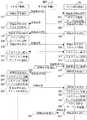
図3は本実施形態の動作シーケンスの一例を示す図である。次に図3のサーバA1(10)がサーバA2(11)に切り替る場合を例に動作のシーケンスを説明する。 FIG. 3 is a diagram illustrating an example of an operation sequence according to the present embodiment. Next, an operation sequence will be described by taking as an example the case where the server A1 (10) in FIG. 3 is switched to the server A2 (11).
まず、サーバA1(10)の切替制御部は、自局の仮想アドレスVAと登録要求日時を示すタイムスタンプ情報をアドレス登録要求としてクライアントB1(20)に対して送信し(ステップ301)、クライアントB1(20)の切替制御部は当該アドレス登録要求を受信する(ステップ302)。当該アドレス登録要求を受信したクライアントB1(20)の切替制御部は、受信したアドレス登録要求内の仮想アドレスVAと当アドレス登録要求の送信元アドレスであるサーバA1(10)の実アドレスRA1の対応をメモリ等の記憶装置上にアドレス管理テーブルとして記憶し(ステップ303)、アドレス登録応答を登録要求送信元であるサーバA1(10)へ送信する(ステップ304)。ステップ303実行後のクライアントB1(20)のアドレス管理テーブルの内容を図4に示す。 First, the switching control unit of the server A1 (10) transmits its own virtual address VA and time stamp information indicating the registration request date and time as an address registration request to the client B1 (20) (step 301), and the client B1. The switching control unit (20) receives the address registration request (step 302). The switching control unit of the client B1 (20) that has received the address registration request associates the virtual address VA in the received address registration request with the real address RA1 of the server A1 (10) that is the transmission source address of the address registration request. Is stored as an address management table on a storage device such as a memory (step 303), and an address registration response is transmitted to the server A1 (10) that is the registration request transmission source (step 304). FIG. 4 shows the contents of the address management table of client B1 (20) after step 303 is executed.
図4は本実施形態のステップ303実行後のアドレス管理テーブルの一例を示す図である。図4に示す様にステップ303実行後のクライアントB1(20)のアドレス管理テーブル45には、仮想アドレスVAとサーバA1(10)の実アドレスRA1の対応を示すデータが格納されており、これらのアドレスの登録要求に付加されているタイムスタンプ情報も格納しておき、以下で説明するタイムスタンプの差の計算の際に用いる様にしても良い。 FIG. 4 is a diagram showing an example of an address management table after execution of step 303 in the present embodiment. As shown in FIG. 4, the address management table 45 of the client B1 (20) after execution of step 303 stores data indicating the correspondence between the virtual address VA and the real address RA1 of the server A1 (10). The time stamp information added to the address registration request may also be stored and used when calculating the time stamp difference described below.
サーバA1(10)の切替制御部はアドレス登録応答を受信し、当仮想アドレスVAを通信で使用可能な様にアドレスを活性化する(ステップ305)。 The switching control unit of the server A1 (10) receives the address registration response and activates the address so that the virtual address VA can be used for communication (step 305).
またクライアントB1(20)の切替制御部は自局の仮想アドレスVBをアドレス登録要求としてサーバA1(10)へ送信し(ステップ306)、サーバA1(10)の切替制御部は当該アドレス登録要求を受信する(ステップ307)。当該アドレス登録要求を受信したサーバA1(10)の切替制御部は、クライアントB1(20)がアドレス登録要求を受信した際と同様に、メモリ等の記憶装置上に受信したアドレス登録要求内の仮想アドレスVBと当アドレス登録要求の送信元アドレスであるクライアントB1(20)の実アドレスRB1の対応をアドレス管理テーブルとして記憶し(ステップ308)、アドレス登録応答を登録要求送信元であるクライアントB1(20)へ送信する(ステップ309)。クライアントB1(20)の切替制御部はアドレス登録応答を受信し、当仮想アドレスVBを通信で使用可能な様にアドレスを活性化する(ステップ310)。 Further, the switching control unit of the client B1 (20) transmits the virtual address VB of its own station to the server A1 (10) as an address registration request (step 306), and the switching control unit of the server A1 (10) sends the address registration request. Receive (step 307). The switching control unit of the server A1 (10) that has received the address registration request performs a virtual process in the address registration request received on the storage device such as a memory, in the same manner as when the client B1 (20) receives the address registration request. The correspondence between the address VB and the real address RB1 of the client B1 (20) that is the transmission source address of the address registration request is stored as an address management table (step 308), and the address registration response is stored in the client B1 (20 (Step 309). The switching control unit of the client B1 (20) receives the address registration response, and activates the address so that the virtual address VB can be used for communication (step 310).
なお、アドレス登録要求は、アドレス登録要求送信先の構成情報を予め用意しておき、TCP(Transmission Control Protocol)コネクション上で通知を行うか、或いはUDP(User Datagram Protocol)のユニキャストでも通知が可能である。また、事前にアドレス登録要求送信先の構成情報を持たせずに、UDPのブロードキャスト等を使用し通知することも可能である。 The address registration request can be notified in advance by preparing the configuration information of the address registration request transmission destination in advance on a TCP (Transmission Control Protocol) connection, or by UDP (User Datagram Protocol) unicast. It is. Also, it is possible to notify using the UDP broadcast or the like without having the configuration information of the address registration request transmission destination in advance.
系切替においては、系切替時にOS等から起動するコールドスタンバイの方式もあり、アドレス登録要求に対する応答が必ず返る保証は無い。従って、TCPコネクション上でアドレス登録要求を通知する場合には、TCPコネクションが確立するまで一定間隔でTCPコネクション確立の試行を繰り返し、TCPコネクションの確立を契機にアドレス登録要求を行う。またUDPで通知する場合にはアドレス登録応答を受信するまで一定間隔でアドレス登録要求の送信を繰り返す等を行うことも考えられる。 In system switching, there is a cold standby system that is started from the OS or the like at the time of system switching, and there is no guarantee that a response to an address registration request is always returned. Therefore, when an address registration request is notified on a TCP connection, an attempt to establish a TCP connection is repeated at regular intervals until the TCP connection is established, and an address registration request is made when the TCP connection is established. In the case of notification by UDP, transmission of an address registration request may be repeated at regular intervals until an address registration response is received.
次に、サーバA1(10)とクライアントB1(20)のトランザクション等の業務処理部の通信用に仮想アドレスVA、VBを使用してコネクションを確立し(ステップ311、312)、サーバA1(10)及びクライアントB1(20)はメモリ等の記憶装置上に当コネクションの状態や仮想アドレス等をコネクション管理テーブルとして記憶する(ステップ313、314)。 Next, a connection is established using the virtual addresses VA and VB for communication between the business processing unit such as a transaction between the server A1 (10) and the client B1 (20) (
ここで、サーバA1(10)の業務処理部の障害等により、サーバA2(11)への系切替が発生した場合、サーバA2(11)の切替制御部は引継ぐ仮想アドレスVAをアドレス登録要求として送信し(ステップ315)、クライアントB1(20)の切替制御部はアドレス登録要求を受信する(ステップ316)。アドレス登録要求を受信したクライアントB1(20)の切替制御部は受信したアドレス登録要求内にある仮想アドレスVAをキーにアドレス管理テーブルを参照し、仮想アドレスVAに対するサーバA1(10)の実アドレスRA1を取得後、当実アドレスのサーバA1(10)に対して仮想アドレスVAをアドレス削除要求として送信する(ステップ317)。サーバA1(10)の切替制御部は当該アドレス削除要求を受信し(ステップ318)、当該削除要求で通知された仮想アドレスVAをキーにコネクション管理テーブルを検索し、当該仮想アドレスVAを使用したコネクションに対して切断処理、例えばそのコネクションを使用している業務処理の強制終了等を行い(ステップ319)、コネクション切断に合わせ当該コネクションに対応するコネクション管理テーブルのデータを削除する(ステップ320)。その後、アドレス削除要求送信元であるクライアントB1(20)へアドレス削除応答を送信し、当仮想アドレスVAで通信できない様にアドレスの非活性化を行う(ステップ321)。 Here, when a system switchover to the server A2 (11) occurs due to a failure of the business processing unit of the server A1 (10), the switching control unit of the server A2 (11) uses the succeeding virtual address VA as an address registration request. The switching control unit of the client B1 (20) receives the address registration request (step 316). The switching control unit of the client B1 (20) that has received the address registration request refers to the address management table using the virtual address VA in the received address registration request as a key, and the real address RA1 of the server A1 (10) for the virtual address VA. Then, the virtual address VA is transmitted as an address deletion request to the server A1 (10) of the actual address (step 317). The switching control unit of the server A1 (10) receives the address deletion request (step 318), searches the connection management table using the virtual address VA notified by the deletion request as a key, and a connection using the virtual address VA. Disconnection processing, for example, forcibly terminate the business process using the connection (step 319), and delete the data in the connection management table corresponding to the connection when the connection is disconnected (step 320). Thereafter, an address deletion response is transmitted to the client B1 (20) as the address deletion request transmission source, and the address is deactivated so that communication cannot be performed with the virtual address VA (step 321).
なお、サーバA1(10)自体が障害の場合には、クライアントB1(20)の切替制御部はアドレス削除応答の受信を期待できないため、所定時間が経過するまで応答の監視を行い、タイムアウトした場合には、ステップ317からステップ323の処理に遷移する。 If the server A1 (10) itself has a failure, the switching control unit of the client B1 (20) cannot expect to receive an address deletion response. The process transitions from
クライアントB1(20)の切替制御部はアドレス削除応答を受信し(ステップ322)、上記アドレス登録要求で通知された仮想アドレスVAをキーに、コネクション管理テーブルを検索し、当該仮想アドレスVAを使用したコネクションに対して切断処理を行い(ステップ323)、コネクション切断に合わせて当該コネクションに対応するコネクション管理テーブルのデータを削除する(ステップ324)。次に、クライアントB1(20)の切替制御部はアドレス管理テーブルの仮想アドレスVAに対応する実アドレスRA1を、アドレス登録要求送信元であるサーバA2(11)の実アドレスRA2に更新し(ステップ325)、上記アドレス登録要求送信元であるサーバA2(11)へアドレス登録応答を送信する(ステップ326)。ステップ325実行後のアドレス管理テーブルの内容を図5に示す。 The switching control unit of the client B1 (20) receives the address deletion response (step 322), searches the connection management table using the virtual address VA notified by the address registration request as a key, and uses the virtual address VA. Disconnection processing is performed on the connection (step 323), and data in the connection management table corresponding to the connection is deleted in accordance with the disconnection of the connection (step 324). Next, the switching control unit of the client B1 (20) updates the real address RA1 corresponding to the virtual address VA in the address management table to the real address RA2 of the server A2 (11) that is the address registration request transmission source (step 325). ), An address registration response is transmitted to the server A2 (11), which is the address registration request transmission source (step 326). FIG. 5 shows the contents of the address management table after
図5は本実施形態のアドレス管理テーブルの一例を示す図である。図5に示す様にステップ325実行後のクライアントB1(20)のアドレス管理テーブル55には、仮想アドレスVAとサーバA2(11)の実アドレスRA2の対応を示すデータが格納されている。 FIG. 5 is a diagram showing an example of the address management table of the present embodiment. As shown in FIG. 5, the address management table 55 of the client B1 (20) after execution of
サーバA2(11)の切替制御部は当該アドレス登録応答を受信し(ステップ327)、ここでシステム切替処理は完了し、サーバA2とクライアントB1間の業務処理で使用するコネクションの再確立を行い、業務の復旧を行う。 The switching control unit of the server A2 (11) receives the address registration response (step 327). Here, the system switching process is completed, and the connection used in the business process between the server A2 and the client B1 is reestablished. Perform business recovery.
なお、本実施形態ではプロトコルをTCP/IPと想定しているが、プロトコルに制限はなく、例えばOSI(Open System Interconnection)等でも良く、この場合にはNSAP(Network Service Access Point)アドレスやPSAP(Presentation Service Access Point)アドレスといったアドレス情報を用いることも可能である。また、仮想アドレスにエリアスIPアドレス、実アドレスに物理IPアドレスを想定しているが、仮想アドレスは系切替を行う単位(サーバ、クライアント、業務等)を識別する為のものであり、識別可能なものであれば単なる識別情報でも良く、アドレス体系に制約は無い。また、物理アドレスについても同様である。 In this embodiment, the protocol is assumed to be TCP / IP, but the protocol is not limited, and may be, for example, OSI (Open System Interconnection) or the like. In this case, an NSAP (Network Service Access Point) address or PSAP ( It is also possible to use address information such as a Presentation Service Access Point address. In addition, an alias IP address is assumed as a virtual address, and a physical IP address is assumed as a real address. However, the virtual address is for identifying a unit (server, client, business, etc.) for performing system switching and can be identified. Any identification information may be used, and there is no restriction on the address system. The same applies to the physical address.
更に、業務処理部が使用するコネクションの切断については、前記アドレス登録要求等を通知する為のTCPコネクション上、或いはUDPで定期的に通信相手とデータを送受信することで生存監視を行い、相手からのデータ受信が一定時間無かったことを契機とすることで、通信相手の障害を早期に検知してコネクションを切断する方法も考えられる。 Further, regarding the disconnection of the connection used by the business processing unit, the existence monitoring is performed by transmitting / receiving data to / from the communication partner periodically on the TCP connection for notifying the address registration request or the like by UDP. It is also conceivable to detect the failure of the communication partner at an early stage and disconnect the connection by using the fact that no data has been received for a certain period of time.
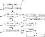
図6は本実施形態のアドレス登録要求受信処理の処理手順を示すフローチャートである。本実施形態の切替制御部は、アドレス登録要求を受信すると、メモリ等の記憶装置上に記憶しているアドレス管理テーブルを参照し(ステップ601)、上記アドレス登録要求で通知された仮想アドレスと重複する仮想アドレスが存在するかを検索し(ステップ602)、存在しない場合には新規登録として当該アドレス管理テーブルに仮想アドレスと上記アドレス登録要求の送信元の実アドレスを追加し(ステップ603)、上記アドレス登録要求の送信元にアドレス登録応答を送信する(ステップ604)。このステップ603及び604は、それぞれ図3におけるステップ303及び304に相当する処理である。重複する仮想アドレスが存在する場合には、同一仮想アドレスの前回の登録要求と今回受信した上記登録要求に付加されたタイムスタンプから差を計算し(ステップ605)、その差が事前定義された所定時間内、例えばアドレス削除要求の送信からアドレス削除応答の受信に要する時間内である場合、上記アドレス登録要求の送信元にアドレス登録拒否を送信し(ステップ606)、複数の予備計算機が存在する等の場合に同一アドレスの所定時間内の登録要求が競合することを回避する。 FIG. 6 is a flowchart showing the processing procedure of the address registration request reception processing of this embodiment. When receiving the address registration request, the switching control unit of the present embodiment refers to an address management table stored on a storage device such as a memory (step 601), and overlaps with the virtual address notified by the address registration request. The virtual address and the real address of the transmission source of the address registration request are added to the address management table as new registration if there is no virtual address (step 603). An address registration response is transmitted to the transmission source of the address registration request (step 604).
またステップ605においてタイムスタンプの差が所定時間より大きい場合、上記アドレス登録要求送信元の実アドレスと上記アドレス登録要求に付加された仮想アドレスを記憶し(ステップ607)、アドレス管理テーブルからアドレス登録要求で通知された仮想アドレスに対応する実アドレスを取得して、当該実アドレスに対して上記アドレス登録要求の仮想アドレスを付加したアドレス削除要求を送信する(ステップ608)。このステップ608は、図3のステップ317に相当する処理である。 If the time stamp difference is larger than the predetermined time in
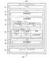
図7は本実施形態のサーバまたはクライアントの各構成要素例を示す図である。図7に示す様に本実施形態のサーバまたはクライアントは、CPU71、メモリ72、及びネットワーク30を接続するネットワークアダプタ79や、各種プログラム及びデータを格納する磁気ディスク(図示せず)等から構成される。また、メモリ72上には、トランザクション等の業務処理を行う業務処理部73、TCP/IP等の通信制御部78を含むOS77の間に系切替を実現する切替制御部74が存在する。 FIG. 7 is a diagram showing an example of each component of the server or client of this embodiment. As shown in FIG. 7, the server or client of this embodiment is composed of a
業務処理部73は、トランザクションやファイル転送処理等、ネットワークを介して他の計算機との通信を行って実際の業務処理を実行する処理部である。切替制御部74は、予備計算機からアドレス登録要求を他計算機へ送信し、予備計算機からアドレス登録要求を受信して現用計算機へ削除要求を送信し、他計算機から削除要求を受信して前記他計算機とのコネクションを切断し、前記他計算機に削除応答を送信し、当該削除応答を受信して現用計算機とのコネクションを切断すると共に、前記アドレス登録要求を送信した予備計算機にアドレス登録応答を送信し、前記予備計算機との間でのコネクション再確立に備える処理部である。なお、切替制御部74は上記要求及び応答を送受信する際に、仮想アドレスと実アドレスの情報を所有するアドレス管理テーブル75、及び業務処理部が使用するコネクションの状態やアドレス等の情報を所有するコネクション管理テーブル76を備え、切替を制御する。 The
サーバまたはクライアントを業務処理部73及び切替制御部74として機能させる為のプログラムは、CD−ROM等の記録媒体に記録され磁気ディスク等に格納された後、メモリにロードされて実行されるものとする。なお前記プログラムを記録する記録媒体はCD−ROM以外の他の記録媒体でも良い。また前記プログラムを当該記録媒体から情報処理装置にインストールして使用しても良いし、ネットワークを通じて当該記録媒体にアクセスして前記プログラムを使用するものとしても良い。 A program for causing a server or a client to function as the
以上説明した様に本実施形態の計算機システムによれば、現用計算機から予備計算機へアドレスを引継ぐ系切替の際に、通信相手の計算機に対して系切替が発生したことを通知すると共に、現用計算機に対しても切替が発生したことを通知することで、現用計算機と待機計算機でのアドレス重複を防止するので、高信頼なスタンバイシステムを平易に構築でき、構築や運用に関するコストを軽減することが可能である。 As described above, according to the computer system of the present embodiment, at the time of system switching that takes over the address from the active computer to the standby computer, the communication partner computer is notified that the system switching has occurred, and the active computer By notifying that the switch has occurred, address duplication between the active computer and the standby computer is prevented, so a highly reliable standby system can be easily constructed, and the costs related to construction and operation can be reduced. Is possible.
10…現用サーバ、11…予備サーバ、20…現用クライアント、21…予備クライアント、30…ネットワーク、201及び202…仮想アドレス、203〜206…実アドレス、45…アドレス管理テーブル、55…アドレス管理テーブル、71…CPU、72…メモリ、73…業務処理部、74…切替制御部、75…アドレス管理テーブル、76…コネクション管理テーブル、77…OS、78…通信制御部、79…ネットワークアダプタ。 DESCRIPTION OF
Claims (4)
Translated fromJapanese現用計算機から予備計算機への系切替の際に予備計算機から当該計算機で使用するアドレスを情報として持つアドレス登録要求を通信装置により送信し、前記予備計算機からアドレス登録要求を受信した他計算機は当該アドレスを使用していた現用計算機に対し当該アドレスを情報として持つアドレス削除要求を送信し、アドレス削除要求を受信した現用計算機は当該アドレス削除要求内にあるアドレスを使用したコネクションを切断後にアドレス削除応答を送信し、アドレス削除応答を受信した他計算機は当アドレスを使用したコネクションを切断後に予備計算機に対しアドレス登録応答を送信し、当該予備計算機と他計算機の間でコネクション確立要求を通信装置により送受信してコネクションを再確立するシステム切替方法であって、
アドレス登録要求にタイムスタンプを付加して、予備計算機からアドレス登録要求を通信装置により受信した後に、更に他の予備計算機から前記アドレスと同一のアドレス登録要求を通信装置により受信すると、各アドレス登録要求に付加されたタイムスタンプの差を計算し所定時間内である場合には、後のアドレス登録要求を送信した当該計算機へアドレス登録拒否を通信装置により送信することを特徴とするシステム切替方法。In a system switching method for switching between an active computer and a standby computer connected via a network,
An address registration request with the address to be used in the computer from the standby computerduring SWITCHING system from the working computer to the standby computer as the information transmitted by the communication device, another computer which has received the address registration request from the preliminary computer the Sends an address deletion request with the address as information to the active computer that used the address, and the active computer that received the address deletion request disconnects the connection using the address in the address deletion request and then responds to the address deletion The other computer that received the address deletion response sends the address registration response to the spare computer after disconnecting the connection using this address, and sends and receives a connection establishment request between the spare computer and the other computer by the communication device.System switching method for re-establishing the connection,
After adding a time stamp to the address registration request and receiving the address registration request from the spare computer by the communication device, each address registration request is received when the same address registration request as the address is received from the other spare computer by the communication device. A system switching method,comprising: calculating a difference between the time stamps added to, and transmitting an address registration refusal by a communication device to a computer that has transmitted a subsequent address registration request when the difference is within a predetermined time .
現用計算機から予備計算機への系切替の際に予備計算機から当該計算機で使用するアドレスを情報として持つアドレス登録要求を通信装置により送信し、前記予備計算機からアドレス登録要求を受信した他計算機は当該アドレスを使用していた現用計算機に対し当該アドレスを情報として持つアドレス削除要求を送信し、アドレス削除要求を受信した現用計算機は当該アドレス削除要求内にあるアドレスを使用したコネクションを切断後にアドレス削除応答を送信し、アドレス削除応答を受信した他計算機は当アドレスを使用したコネクションを切断後に予備計算機に対しアドレス登録応答を送信し、当該予備計算機と他計算機の間でコネクション確立要求を通信装置により送受信してコネクションを再確立する計算機システムであって、
アドレス登録要求にタイムスタンプを付加して、予備計算機からアドレス登録要求を通信装置により受信した後に、更に他の予備計算機から前記アドレスと同一のアドレス登録要求を通信装置により受信すると、各アドレス登録要求に付加されたタイムスタンプの差を計算し所定時間内である場合には、後のアドレス登録要求を送信した当該計算機へアドレス登録拒否を通信装置により送信することを特徴とする計算機システム。In a computer system that switches between a working computer and a spare computer connected via a network,
Was transmitted by the communication device an address registration request with the address to be used in the computer from the standby computer during system switching from thecurrent computer for the spare computer as the information, other computers that received the address registration request from the preliminary computer the Sends an address deletion request with the address as information to the active computer that used the address, and the active computer that received the address deletion request disconnects the connection using the address in the address deletion request and then responds to the address deletion transmits thetransmits the other computer address registration response tospare computerafter cutting the connection using those addresses that received the address deletionresponse, the communication device connection establishment request between the pre-computer and other computers A computer system that re-establishes a connection by sending and receiving by
After adding a time stamp to the address registration request and receiving the address registration request from the spare computer by the communication device, each address registration request is received when the same address registration request as the address is received from the other spare computer by the communication device. A computer system comprising: calculating a difference between the time stamps added to the time stamp and, within a predetermined time, transmitting an address registration refusal by a communication device to the computer that has transmitted a subsequent address registration request .
現用計算機から予備計算機への系切替の際に予備計算機から当該計算機で使用するアドレスを情報として持つアドレス登録要求を通信装置により送信し、前記予備計算機からアドレス登録要求を受信した他計算機は当該アドレスを使用していた現用計算機に対し当該アドレスを情報として持つアドレス削除要求を送信し、アドレス削除要求を受信した現用計算機は当該アドレス削除要求内にあるアドレスを使用したコネクションを切断後にアドレス削除応答を送信し、アドレス削除応答を受信した他計算機は当アドレスを使用したコネクションを切断後に予備計算機に対しアドレス登録応答を送信し、当該予備計算機と他計算機の間でコネクション確立要求を通信装置により送受信してコネクションを再確立するシステム切替方法であって、
アドレス登録要求にタイムスタンプを付加して、予備計算機からアドレス登録要求を通信装置により受信した後に、更に他の予備計算機から前記アドレスと同一のアドレス登録要求を通信装置により受信すると、各アドレス登録要求に付加されたタイムスタンプの差を計算し所定時間内である場合には、後のアドレス登録要求を送信した当該計算機へアドレス登録拒否を通信装置により送信するシステム切替方法をコンピュータに実行させることを特徴とするプログラム。In a program for causing a computer to execute a system switching method for switching between an active computer and a standby computer connected via a network,
An address registration request with the address to be used in the computer from the standby computerduring SWITCHING system from the working computer to the standby computer as the information transmitted by the communication device, another computer which has received the address registration request from the preliminary computer the Sends an address deletion request with the address as information to the active computer that used the address, and the active computer that received the address deletion request disconnects the connection using the address in the address deletion request and then responds to the address deletion The other computer that received the address deletion response sends the address registration response to the spare computer after disconnecting the connection using this address, and sends and receives a connection establishment request between the spare computer and the other computer by the communication device.System switching method for re-establishing the connection,
After adding a time stamp to the address registration request and receiving the address registration request from the spare computer by the communication device, each address registration request is received when the same address registration request as the address is received from the other spare computer by the communication device. When the difference between the time stamps added to is calculated and within a predetermined time, the computer is caused to executea system switching method in whicha communication device transmits an address registration refusal to the computer that sent the subsequent address registration request. A featured program.
Priority Applications (1)
| Application Number | Priority Date | Filing Date | Title |
|---|---|---|---|
| JP2006072918AJP4757670B2 (en) | 2006-03-16 | 2006-03-16 | System switching method, computer system and program thereof |
Applications Claiming Priority (1)
| Application Number | Priority Date | Filing Date | Title |
|---|---|---|---|
| JP2006072918AJP4757670B2 (en) | 2006-03-16 | 2006-03-16 | System switching method, computer system and program thereof |
Publications (2)
| Publication Number | Publication Date |
|---|---|
| JP2007249659A JP2007249659A (en) | 2007-09-27 |
| JP4757670B2true JP4757670B2 (en) | 2011-08-24 |
Family
ID=38593876
Family Applications (1)
| Application Number | Title | Priority Date | Filing Date |
|---|---|---|---|
| JP2006072918AExpired - Fee RelatedJP4757670B2 (en) | 2006-03-16 | 2006-03-16 | System switching method, computer system and program thereof |
Country Status (1)
| Country | Link |
|---|---|
| JP (1) | JP4757670B2 (en) |
Families Citing this family (4)
| Publication number | Priority date | Publication date | Assignee | Title |
|---|---|---|---|---|
| JP5351448B2 (en)* | 2008-06-30 | 2013-11-27 | アズビル株式会社 | Server client system and server switching method |
| JP5231461B2 (en)* | 2010-01-29 | 2013-07-10 | 富士通フロンテック株式会社 | Information processing system, information processing apparatus, communication control program, and communication control method |
| JP6205898B2 (en)* | 2013-06-27 | 2017-10-04 | 富士通株式会社 | Control method, control program, and information processing system |
| JP6217358B2 (en)* | 2013-12-02 | 2017-10-25 | 富士通株式会社 | Information processing apparatus and recovery management method |
Family Cites Families (9)
| Publication number | Priority date | Publication date | Assignee | Title |
|---|---|---|---|---|
| JPH07182297A (en)* | 1993-12-24 | 1995-07-21 | Nec Corp | Server/client type network system |
| JPH09259096A (en)* | 1996-03-27 | 1997-10-03 | Hitachi Ltd | Network high reliability method and system |
| JPH10320323A (en)* | 1997-05-15 | 1998-12-04 | Hewlett Packard Japan Ltd | Server computer and method for controlling server computer and recording medium for recording program for controlling server computer |
| JP2000276365A (en)* | 1999-03-23 | 2000-10-06 | Fujitsu Ltd | Client server system and monitoring system |
| JP2002328885A (en)* | 2001-04-27 | 2002-11-15 | Sumisho Computer Systems Corp | Clustering system and method, data processing device, clustering program, recording medium |
| JP2003076571A (en)* | 2001-08-31 | 2003-03-14 | Pfu Ltd | Redundant system and its server |
| JP2003084996A (en)* | 2001-09-11 | 2003-03-20 | Hitachi Ltd | How to switch host computer |
| JP2004171370A (en)* | 2002-11-21 | 2004-06-17 | Nec Corp | Address control system and method between client/server in redundant constitution |
| JP2006050228A (en)* | 2004-08-04 | 2006-02-16 | Advanced Telecommunication Research Institute International | Wireless network system |
- 2006
- 2006-03-16JPJP2006072918Apatent/JP4757670B2/ennot_activeExpired - Fee Related
Also Published As
| Publication number | Publication date |
|---|---|
| JP2007249659A (en) | 2007-09-27 |
Similar Documents
| Publication | Publication Date | Title |
|---|---|---|
| JP3932994B2 (en) | Server handover system and method | |
| US20040049553A1 (en) | Information processing system having data migration device | |
| JP5863942B2 (en) | Provision of witness service | |
| CN100369413C (en) | Proxy-response device and method for proxy-response device | |
| CN111190747A (en) | Message loss detection method and device for message queue | |
| TW201824823A (en) | Methods and devices for switching a virtual internet protocol address | |
| US20060164974A1 (en) | Method of moving a transport connection among network hosts | |
| JP4616159B2 (en) | Cluster system, load balancer, node transfer method, and node transfer program | |
| CN102946405A (en) | SMB2 extension | |
| CN106330475A (en) | A method and device for managing active and standby nodes in a communication system and a high-availability cluster | |
| JP5419907B2 (en) | Network system and communication recovery method | |
| JP2013161251A (en) | Computer failure monitoring program, method, and device | |
| US8850056B2 (en) | Method and system for managing client-server affinity | |
| CN107203443A (en) | A kind of method and apparatus of the virtual machine High Availabitity based on KVM virtualization | |
| JP2010103695A (en) | Cluster system, cluster server and cluster control method | |
| JPH08212095A (en) | Client server control system | |
| JP4757670B2 (en) | System switching method, computer system and program thereof | |
| JPH09259096A (en) | Network high reliability method and system | |
| JP3608905B2 (en) | Data communication system and data communication method | |
| JP4806382B2 (en) | Redundant system | |
| KR100597405B1 (en) | Data relay system and data relay method using socket application program | |
| JP4133738B2 (en) | High-speed network address takeover method, network device, and program | |
| CN103188065A (en) | Method and system of data synchronism in business service | |
| JP2001244977A (en) | Data transfer device, data transfer system, data transfer method, and storage medium | |
| JP2007133542A (en) | Information takeover system, information takeover method, active node and standby node |
Legal Events
| Date | Code | Title | Description |
|---|---|---|---|
| A621 | Written request for application examination | Free format text:JAPANESE INTERMEDIATE CODE: A621 Effective date:20090126 | |
| A977 | Report on retrieval | Free format text:JAPANESE INTERMEDIATE CODE: A971007 Effective date:20101028 | |
| A131 | Notification of reasons for refusal | Free format text:JAPANESE INTERMEDIATE CODE: A131 Effective date:20101109 | |
| A521 | Written amendment | Free format text:JAPANESE INTERMEDIATE CODE: A523 Effective date:20110107 | |
| TRDD | Decision of grant or rejection written | ||
| A01 | Written decision to grant a patent or to grant a registration (utility model) | Free format text:JAPANESE INTERMEDIATE CODE: A01 Effective date:20110531 | |
| A01 | Written decision to grant a patent or to grant a registration (utility model) | Free format text:JAPANESE INTERMEDIATE CODE: A01 | |
| A61 | First payment of annual fees (during grant procedure) | Free format text:JAPANESE INTERMEDIATE CODE: A61 Effective date:20110601 | |
| R150 | Certificate of patent or registration of utility model | Ref document number:4757670 Country of ref document:JP Free format text:JAPANESE INTERMEDIATE CODE: R150 Free format text:JAPANESE INTERMEDIATE CODE: R150 | |
| FPAY | Renewal fee payment (event date is renewal date of database) | Free format text:PAYMENT UNTIL: 20140610 Year of fee payment:3 | |
| LAPS | Cancellation because of no payment of annual fees |