JP4757403B2 - Solid material vaporizer - Google Patents
Solid material vaporizerDownload PDFInfo
- Publication number
- JP4757403B2 JP4757403B2JP2001166050AJP2001166050AJP4757403B2JP 4757403 B2JP4757403 B2JP 4757403B2JP 2001166050 AJP2001166050 AJP 2001166050AJP 2001166050 AJP2001166050 AJP 2001166050AJP 4757403 B2JP4757403 B2JP 4757403B2
- Authority
- JP
- Japan
- Prior art keywords
- raw material
- solid
- material container
- heating
- vaporizer
- Prior art date
- Legal status (The legal status is an assumption and is not a legal conclusion. Google has not performed a legal analysis and makes no representation as to the accuracy of the status listed.)
- Expired - Fee Related
Links
Images


Landscapes
- Chemical Vapour Deposition (AREA)
Description
Translated fromJapanese【0001】
【発明の属する技術分野】
本発明は、固体原料気化装置に関する。
【0002】
【従来の技術】
半導体デバイスの製造プロセスにおいては、被処理体である半導体ウエハに例えばCVD(化学気相成長)等の熱処理を施すために、熱処理装置が使用されている。そして、半導体デバイスの微細化と共に半導体デバイスに使用される膜も例えばTa2O5、Ruといった金属系の膜へと変化してきている。
【0003】
これらの金属系の原料は、有機金属が一般的であるが、室温で固体のものも多く存在する。室温で固体の原料は、一般的には有機溶媒に溶解し、気化器へ液体の形で導入されるが、固体のままで十分な蒸気圧が確保できるもの、もしくは、溶媒への溶解が困難なものについては固体の状態から昇華させるという手法が用いられている。
【0004】
この固体昇華法においては、例えば図7の(a)に示すように、固体原料12を収容した原料容器(原料ボトルともいう)13の外側にヒータ14を設け、このヒータ14により原料容器13内の固体原料12を加熱して気化させる固体原料気化装置が用いられる。そして、この固体原料気化装置により発生した気化ガスは、ガス供給系11により熱処理装置に供給され、半導体ウエハの所定の熱処理例えば成膜処理に供される。
【0005】
【発明が解決しようとする課題】
しかしながら、前述した従来の固体原料気化装置においては、熱伝導の関係で固体原料12を十分に加熱することが難しく、気化ガスを安定して発生させることが困難であった。すなわち、前記固体原料発生装置では、原料容器13から固体原料12への熱伝導の関係で原料容器13内における固体原料12の中央領域Aと周縁領域Bの間に温度勾配が生じ、固体原料12の昇華速度が周縁領域Bよりも中央領域Aの方が遅くなる傾向がある。このため、図7の(b)に示すように、固体原料12が山状に減るようになり、固体原料12の周縁領域が原料容器13の周側壁と接しなくなると、加熱されにくくなって昇華速度が落ち、気化ガスの発生が不安定になる。また、このような現象は、原料容器の容量が大きくなるほど顕著になるため、半導体ウエハの量産を見据えての固体原料気化装置の容量のアップが難しかった。
【0006】
本発明は、前記事情を考慮してなされたもので、原料容器内の固体原料を中央領域と周縁領域の間に温度勾配を生じさせずに十分に加熱することができ、気化ガスを安定して発生させることができる固体原料気化装置を提供することを目的とする。
【0007】
【課題を解決するための手段】
本発明のうち、請求項1の発明は、固体原料を収容した原料容器と、該原料容器を加熱する加熱手段とを備えた固体原料気化装置において、前記原料容器内に固体原料を加熱するための加熱部および熱伝導部材を配設し、前記熱伝導部材が、前記原料容器内に上下方向に設けられた螺旋状のフィンからなることを特徴とする。
【0008】
請求項2の発明は、請求項1記載の固体原料気化装置において、前記螺旋状のフィンには複数の孔が形成されていることを特徴とする。
【0009】
請求項3の発明は、請求項1記載の固体原料気化装置において、前記原料容器内の底部には複数の中空管が前記螺旋状のフィンを上下方向に貫通するように立設され、前記加熱部として前記中空管内には抵抗発熱体が設けられていることを特徴とする。
【0010】
請求項4の発明は、固体原料を収容した原料容器と、該原料容器を加熱する加熱手段とを備えた固体原料気化装置において、前記原料容器内に固体原料を加熱するための加熱部および熱伝導部材を配設し、前記熱伝導部材が、前記原料容器内の底部に立設された支柱と、該支柱に上下方向に適宜間隔で棚状に設けられた網状または多孔状の熱伝導板とからなることを特徴とする。
【0011】
請求項5の発明は、前記支柱が中空管とされ、前記加熱部として前記中空管の内部に温度制御可能なヒータが設けられていることを特徴とする。
【0013】
請求項6の発明は、請求項1または4記載の固体原料気化装置において、前記加熱手段が恒温槽であることを特徴とする。
【0015】
【発明の実施の形態】
以下に、本発明の実施の形態を添付図面に基いて詳述する。図1は本発明の実施の形態でない参考例としての固体原料気化を示す断面図である。
【0016】
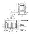
図1において、1は熱処理装置で、10はその熱処理装置1に処理ガスとしての気化ガスを発生供給する固体原料気化装置である。先ず、熱処理装置1について説明すると、熱処理装置1は被処理体例えば半導体ウエハWを収容し、処理ガスを供給して例えば850℃程度の高温下で所定の熱処理例えばCVD処理を施す縦型でバッチ式の熱処理炉を構成するものとして、上端が閉塞され下端が開放された縦長円筒状の例えば石英製の処理容器(反応管ともいう)2を備えている。
【0017】
この処理容器2は、炉口として開放した下端開口部が蓋体3で気密に閉塞されることにより、気密性の高い熱処理炉1を構成するようになっている。前記蓋体3上には、多数枚例えば50〜100枚程度の半導体ウエハWを水平状態で上下方向に間隔をおいて多段に搭載支持する基板支持具である例えば石英製のウエハボート4が保温筒5を介して載置されている。
【0018】
蓋体3は、図示しない昇降機構により、熱処理炉1内へのウエハボート4のロード(搬入)ならびにアンロード(搬出)および炉口の開閉を行うように構成されている。また、前記処理容器2の周囲には、炉内を所定の温度例えば300〜1000℃程度に加熱する温度制御可能に構成された円筒状のヒーターHが設けられている。
【0019】
処理容器2の下側部には、処理容器2内に処理ガスを導入するガス導入管部6と、処理容器内2を排気する排気管部7とが設けられている。ガス導入管部6には、例えば固体原料気化装置10のガス供給系11の配管17が接続されている。また、排気管部7には、処理容器2内を例えば最大10-3Torr程度に減圧可能な真空ポンプおよび圧力制御弁を有する排気系8が接続されている。
【0020】
前記固体原料気化装置10は、固体原料12を収容した原料容器13と、この原料容器13を加熱する加熱手段であるヒータ14とを備えて構成されている。また、固体原料気化装置10は、前記固体原料12から発生した気化ガスを供給する配管17を備えている。固体原料12としては、例えばルテニウム系プロセスの場合、ルテニウム(Ru)を化学的に含有した金属粉末が用いられる。タンタル系プロセスの場合、タンタル(Ta)を化学的に含有した金属粉末が用いられる。
【0021】
前記原料容器13は、例えば有底円筒状の容器本体15と、この容器本体15の上部に気密状態に取付けられた蓋16とから構成されている。この蓋16には、前記配管17の一端が原料容器13内部と連通するように接続されている。この配管17には弁18および流量制御機構19が原料容器13側から順に設けられている。前記弁18としては、例えば手動弁、エアオペレイト弁、ニードル弁等が含まれる。これら原料容器13、配管17、弁18および流量制御機構19がガス供給系11を構成している。このガス供給系11の配管17の露出部には、気化ガスの凝結を起こさない所定の温度例えば200℃程度に加熱する温度制御可能に構成されたリボン状のヒータ20が巻き付けられ、断熱材で覆われていることが好ましい。
【0022】
前記原料容器13を加熱するヒータ14は、原料容器13の底部を加熱する底部ヒータ14aと、原料容器13の周側部を加熱する周側部ヒータ14bとかなり、原料容器13内の固体原料12をその昇華温度例えばルテニウム化合物の場合、190℃程度に加熱し得るように温度制御可能に構成されている。
【0023】
そして、原料容器13内の底部には、該原料容器13からの熱を伝えて原料容器13内の中央領域Aの固体原料12を加熱するための熱伝導部材として複数のフィン21が立設されている。前記原料容器13は、例えばステンレス製もしくはアルミニウム製であり、前記フィン21は原料容器13と同じ材料で形成されていることが好ましい。また、前記原料容器13は、断熱材22で覆われていることが好ましい。
【0024】
以上のように構成において、熱処理装置1で熱処理を行う場合には、先ず、半導体ウエハWを搭載したボート4を熱処理炉の処理容器2内にロードし、炉口を蓋体3で密閉し、排気系8により処理容器2内を所定の処理圧力に排気制御すると共にヒータHにより半導体ウエハwを所定の処理温度に加熱する。また、固体原料気化装置10のヒータ14を作動させて原料容器13内の固体原料12を所定の温度に加熱し、固体原料12から昇華により気化ガスを発生させる。
【0025】
ヒータ14を構成する底部ヒータ14aおよび周側部ヒータ14bにより原料容器13の底部および周側部が加熱され、原料容器13の底部からの熱伝導によりフィン21が加熱され、また、容器本体13からの熱伝導により蓋16も加熱される。これにより固体原料12の原料容器13と接する部分およびフィン21と接する部分が加熱されるため、原料容器13内の固体原料12を中央領域Aと周縁領域Bの間に温度差ないし温度勾配を生じさせずに十分に加熱することができ、気化ガスを安定して発生供給することができる。
【0026】
固体原料12から気化した処理ガスは、所定の蒸気圧となって原料容器13内に充満し、ガス供給系11の弁18を開けると、ガス供給系11の配管17を通り、流量制御機構19を介して所定の流量に制御されながら前記熱処理装置1の処理容器2内に導入され、半導体ウエハwの所定の熱処理例えば成膜処理に供される。
【0027】
このように、前記固体原料気化装置10によれば、固体原料12を収容した原料容器13と、この原料容器13を加熱するヒータ14とを備え、前記原料容器13内に該原料容器13からの熱を伝えて中央領域Aの固体原料12を加熱するための熱伝導部材が配設され、本実施の形態では、前記熱伝導部材が前記原料容器13内の底部に立設された複数のフィン21からなるため、原料容器13内の固体原料12を中央領域Aと周縁領域Bの間に温度勾配を生じさせずに十分に加熱することが可能となり、気化ガスを安定して発生させることができる。
【0028】
また、固体原料気化方法によれば、固体原料12を収容した原料容器13を加熱すると共に、該原料容器13内に配設した熱伝導部材であるフィン21により固体原料12全体を略均一に加熱して、固体原料12から気化ガスを発生させるため、原料容器13内の固体原料12を中央領域Aと周縁領域Bの間に温度勾配を生じさせずに十分に加熱することができ、気化ガスを安定して発生させることができる。従って、半導体ウエハWの量産を見据えての固体原料気化装置10の容量のアップ(大容量化)も可能となる。そして、前記固体原料気化装置10を熱処理装置1の処理ガス供給源として用いれば、気化ガスを安定して供給することができ、熱処理を安定して行うことが可能となる。
【0029】
なお、前記原料容器13内には、熱伝導部材例えばフィン21の代りに抵抗発熱体からなる加熱部26を設けてもよく、あるいは、フィン21および加熱部26を共に設けてもよい。加熱部26は制御部40によって所定の温度に制御されるように構成されている。このように原料容器13内に加熱部26を設けることにより、原料容器13内の固体原料12を直接的に加熱することができる。またこの方法によれば、固体原料13を収容した原料容器12を加熱すると共に、該原料容器12内に配設した加熱部26およびこれに接続された熱伝導部例えばフィン21により固体原料12全体をむらなく略均一に加熱することができる。従って、原料容器13内の固体原料12を中央領域Aと周縁領域Bの間に温度勾配を生じさせずに十分に加熱することが可能となり、気化ガスを安定して発生させることができる。
【0030】
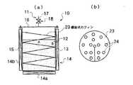
図2は本発明の実施の形態でない固体原料気化装置の参考例を示す図で、(a)は縦断面図、(b)は横断面図である。図2の参考例において、図1の参考例と同じ部分は同じ参照符号を付して説明を省略し、異なる部分について説明を加える。図2に示すように、前記原料容器13内には、熱伝導部材として、上下方向に螺旋状のフィン23が設けられている。螺旋状のフィン23は、原料容器13の内周壁(周側壁)に接していて、溶接により固定されている。螺旋状のフィン23には、複数の孔24が形成されていることが好ましい。以上の構成からなる固体原料気化装置10によれば、熱伝導部材として、原料容器13内に上下方向に螺旋状のフィン23が原料容器13の内周壁に接して設けられているため、原料容器13の周側部から螺旋状のフィン23への熱伝導により、原料容器13内の固体原料12を中央領域Aと周縁領域Bの間に温度勾配を生じさせずに十分に加熱することが可能となり、図1の参考例と同様の効果を奏することができる。
【0031】
また、前記螺旋状のフィン23に複数の孔24を形成すれば、これらの孔24を通して固体原料12からの気化ガスを上方へ円滑に導くことができ、固体原料12からの気化を促進することができる。すなわち、固体原料からの気化は、気相と接する固体原料の表面(上面)で行われるため、この表面が螺旋状のフィン23で覆われていると飽和蒸気圧になって気化が抑制されてしまう。これを防止するために、前記孔24が形成されている。
【0032】
図3は本発明の実施の形態である固体原料気化装置の一例を示す図で、(a)は縦断面図、(b)は横断面図である。図3の実施の形態において、図2の参考例と同じ部分は同じ参照符号を付して説明を省略し、異なる部分について説明を加える。図3に示すように、原料容器13内には、熱伝導部材として、上下方向に螺旋状のフィン23が設けられていると共に、この螺旋状のフィン23を上下方向に貫通するように原料容器13内の底部に複数の中空管25が立設されている。この場合、中空管25内には、抵抗発熱体からなる加熱部26が温度制御可能に設けられていてもよい。
【0033】
以上の構成からなる固体原料気化装置10によれば、原料容器13内の固体原料12を中央領域と周縁領域の間に温度勾配を生じさせずに十分に加熱することが可能となり、図1ないし図2の実施の形態と同様の効果を奏することができる。また、前記中空管25内にヒータ26を有する構造とすれば、固体原料12を更に十分に加熱することが可能となる。
【0034】
図4は固体原料気化装置の他の例を示す縦断面図である。図4の実施の形態において、図1の実施の形態と同じ部分は同じ参照符号を付して説明を省略し、異なる部分について説明を加える。図4に示すように、原料容器13内の底部には、熱伝導部材として、支柱27が立設され、この支柱27に上下方向に適宜間隔で棚状に設けられた網状または多孔状の熱伝導板28が設けられている。熱伝導板28としては、例えば金属線を平面方向だけでなく厚さ方向にも立体的に編み込んだメッシュ、もしくは、多数の孔を有する多孔板であることが好ましい。また、前記支柱27は、中空管とされ、内部に温度制御可能なヒータが設けられていることが好ましい。
【0035】
以上の構成からなる固体原料気化装置10によれば、熱伝導部材として、前記原料容器13内の底部に支柱27を立設し、この支柱27に上下方向に適宜間隔で棚状に網状または多孔状の熱伝導板28を設けているため、原料容器13の底部から支柱27を介して熱伝導板28への熱伝導により、原料容器13内の固体原料12を中央領域と周縁領域の間に温度勾配を生じさせずに十分に加熱することが可能となり、図1の実施の形態と同様の効果を奏することができる。また、前記支柱27が加熱部を有する構造とすれば、固体原料12を更に十分に加熱することが可能となる。
【0036】
図5は固体原料気化装置の参考例を示す縦断面図である。図5の参考例おいて、図1の参考例と同じ部分は同じ参照符号を付して説明を省略し、異なる部分について説明を加える。図5に示すように、原料容器13内には、原料容器13との接触頻度を多くすべく固体原料12を攪拌する攪拌手段例えば攪拌翼29が設けられている。この攪拌翼29の駆動軸30は、原料容器13の底部を気密に貫通するように設けられているが、容器本体13の蓋16を気密に貫通するように設けられていてもよい。
【0037】
以上の構成からなる固体原料気化装置10によれば、原料容器13内には、固体原料12を攪拌する攪拌翼29が設けられているため、固体原料12の原料容器13との接触頻度を多くなり、原料容器13内の固体原料12を中央領域と周縁領域の間に温度勾配を生じさせずに十分に加熱することが可能となり、図1の実施の形態と同様の効果を奏することができる。また、この方法によれば、固体原料12を収容した原料容器13を加熱すると共に、該原料容器13内に配設した攪拌手段例えば攪拌翼29により固体原料12を攪拌することにより、固体原料12全体を略均一に加熱して、固体原料12から気化ガスを安定して発生させることができる。
【0038】
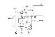
図6は固体原料気化装置の他の例を示す縦断面図である。図6の実施の形態において、図1の実施の形態と同じ部分は同じ参照符号を付して説明を省略し、異なる部分について説明を加える。本実施の形態の固体原料気化装置10は、図6に示すように、原料容器13を加熱する加熱手段として恒温槽31が用いられている。
【0039】
この恒温槽31は、図示しない断熱材で覆われ、内部に例えばステンレス等の金属板で区画された加熱室32が設けられている。この加熱室32の両側壁には多数の通気孔33が設けられている。また、恒温槽31内には、内部雰囲気例えば空気が加熱室内32を通過するように循環するための通風路34が設けられ、この通風路34には、所定の温度に温度制御可能に構成された抵抗発熱体からなるヒータ35と、送風ファン36とが設けられている。そして、前記加熱室32内に、前記原料容器12および弁18が収容されている。なお、前記原料容器内には、前記実施の形態で示したような加熱部および/または熱伝導部材あるいは攪拌手段が設けられている(図示省略)。
【0040】
以上の構成からなる固体原料気化装置10によれば、原料容器13を加熱する加熱手段が恒温槽31からなるため、原料容器13全体を一定の温度で均一に加熱することができ、原料容器13内に設けられている熱伝導部材と相俟って原料容器13内の固体原料を中央領域と周縁領域の間に温度勾配を生じさせずに更に十分に加熱することができ、気化ガスを更に安定して発生させることができる。
【0041】
以上、本発明の実施の形態を図面により詳述してきたが、本発明は前記実施の形態に限定されるものではなく、本発明の要旨を逸脱しない範囲での種々の設計変更等が可能である。例えば、熱処理炉としては、枚葉式であってもよく、横型であってもよい。固体原料としては、粉末状以外に、例えば粒状であってもよい。被処理体としては、半導体ウエハ以外に、例えばガラス基板やLCD基板等であってもよい。また、前記原料容器内には、加熱部、熱伝導部材、攪拌手段を適宜組合わせて配設してもよい。
【0042】
【発明の効果】
以上要するに本発明によれば、次のような効果を奏することができる。
【0043】
(1)請求項1の発明によれば、固体原料を収容した原料容器と、該原料容器を加熱する加熱手段とを備えた固体原料気化装置において、前記原料容器内に固体原料を加熱するための加熱部および熱伝導部材を配設し、前記熱伝導部材が、前記原料容器内に上下方向に設けられた螺旋状のフィンからなるため、原料容器内の固体原料を中央領域と周縁領域の間に温度勾配を生じさせずに十分に加熱することができ、気化ガスを安定して発生させることができる。
【0044】
(2)請求項2の発明によれば、前記螺旋状のフィンには複数の孔が形成されているため、固体原料からの気化を促進することができる。
【0045】
(3)請求項3の発明によれば、前記原料容器内の底部には複数の中空管が前記螺旋状のフィンを上下方向に貫通するように立設され、前記加熱部として前記中空管の内部には抵抗発熱体が温度制御可能に設けられているため、原料容器内の固体原料を中央領域と周縁領域の間に温度勾配を生じさせずに十分に加熱することができ、気化ガスを安定して発生させることができる。
【0047】
(4)請求項4の発明によれば、固体原料を収容した原料容器と、該原料容器を加熱する加熱手段とを備えた固体原料気化装置において、前記原料容器内に固体原料を加熱するための加熱部および熱伝導部材を配設し、前記熱伝導部材が、前記原料容器内の底部に立設された支柱と、該支柱に上下方向に適宜間隔で棚状に設けられた網状または多孔状の熱伝導板とからなるため、原料容器内の固体原料を中央領域と周縁領域の間に温度勾配を生じさせずに十分に加熱することができ、気化ガスを安定して発生させることができる。
【0048】
(5)請求項5の発明によれば、前記支柱が中空管とされ、前記加熱部として前記中空管の内部に温度制御可能なヒータが設けられているため、固体原料を十分に加熱することができる。
【0049】
(6)請求項6の発明によれば、前記加熱手段が恒温槽からなるため、固体原料容器全体を一定の温度で均一に加熱することができ、原料容器内の加熱部、熱伝導部材もしくは攪拌手段と相俟って原料容器内の固体原料を中央領域と周縁領域の間に温度勾配を生じさせずに更に十分に加熱することができ、気化ガスを更に安定して発生させることができる。
【図面の簡単な説明】
【図1】本発明の実施の形態でない固体原料気化装置の参考例を概略的に示す図である。
【図2】本発明の実施の形態でない固体原料気化装置の参考例を示す図で、(a)は縦断面図、(b)は横断面図である。
【図3】本発明の実施の形態である固体原料気化装置の一例を示す図で、(a)は縦断面図、(b)は横断面図である。
【図4】固体原料気化装置の他の例を示す縦断面図である。
【図5】本発明の実施の形態でない固体原料気化装置の他の参考例を示す縦断面図である。
【図6】本発明の実施の形態である固体原料気化装置の他の例を示す縦断面図である。
【図7】従来の固体原料気化装置を示す図で、(a)は固体原料が充填された状態の断面図、(b)は固体原料が少なくなった状態の断面図である。
【符号の説明】
10 固体原料気化装置
12 固体原料
13 原料容器
14 ヒータ(加熱手段)
21 フィン(熱伝導部材)
23 螺旋状のフィン(熱伝導部材)
26 加熱部
27 支柱
28 熱伝導板
29 攪拌翼(攪拌手段)
31 恒温槽(加熱手段)[0001]
BACKGROUND OF THE INVENTION
The present invention relatesto a solid material vaporizingequipment.
[0002]
[Prior art]
In a semiconductor device manufacturing process, a heat treatment apparatus is used to perform a heat treatment such as CVD (Chemical Vapor Deposition) on a semiconductor wafer which is an object to be processed. Along with the miniaturization of semiconductor devices, films used for semiconductor devices are also changing to metal films such as Ta2 O5 and Ru.
[0003]
These metal-based raw materials are generally organic metals, but many of them are solid at room temperature. Raw materials that are solid at room temperature are generally dissolved in an organic solvent and introduced into the vaporizer in the form of a liquid. However, it is possible to ensure a sufficient vapor pressure as a solid or it is difficult to dissolve in a solvent. For such things, a technique of sublimating from a solid state is used.
[0004]
In this solid sublimation method, for example, as shown in FIG. 7A, a
[0005]
[Problems to be solved by the invention]
However, in the conventional solid raw material vaporizer described above, it is difficult to sufficiently heat the solid
[0006]
The present invention has been made in consideration of the above circumstances, and can sufficiently heat the solid raw material in the raw material container without causing a temperature gradient between the central region and the peripheral region, thereby stabilizing the vaporized gas. it is generated Te and to providea solid material vaporizingequipment capable.
[0007]
[Means for Solving the Problems]
Among the present inventions, the invention of claim 1 is a solid raw material vaporizer comprising a raw material container containing a solid raw material and a heating means for heating the raw material container, for heating the solid raw material in the raw material container. to install heating portionand the heat conduction member, the heat conducting member, characterized by comprising the spiral fins provided in the vertical direction in the material container.
[0008]
According to a second aspect of the present invention, in the solid material vaporizer according to the first aspect, thespiral fin is formed with a plurality of holes .
[0009]
According to a third aspect of the present invention, there is provided the solid raw material vaporizer according to the first aspect, wherein aplurality of hollow tubes are erected on the bottom of the raw material container so as to vertically penetrate the spiral fins, A resistance heating element is provided in the hollow tube as a heating unit .
[0010]
According to a fourth aspect of the present invention, there is provided a solid raw material vaporizer including a raw material container containing a solid raw material and a heating means for heating the raw material container, and a heating unit and a heating unit for heating the solid raw material in the raw material container.And a heat conduction member, and the heat conduction member is a column or a porous heat column provided in a shelf shape at appropriate intervals in the vertical direction on the column. It consists of a conductive plate.
[0011]
The invention of
[0013]
Asixth aspect of the present invention is the solid raw material vaporizer according to the first orfourth aspect ,wherein the heating means is a thermostatic bath .
[0015]
DETAILED DESCRIPTION OF THE INVENTION
Hereinafter, embodiments of the present invention will be described in detail with reference to the accompanying drawings. FIG. 1 is a cross-sectional view showing solid raw material vaporizationas a reference example which is not an embodiment of the present invention.
[0016]
In FIG. 1, 1 is a heat treatment apparatus, and 10 is a solid material vaporization apparatus that generates and supplies vaporized gas as a treatment gas to the heat treatment apparatus 1. First, the heat treatment apparatus 1 will be described. The heat treatment apparatus 1 accommodates an object to be processed such as a semiconductor wafer W, supplies a processing gas, and performs a predetermined heat treatment such as a CVD process at a high temperature of about 850 ° C. As a constituent of a heat treatment furnace of the type, a vertically long cylindrical processing vessel (also referred to as a reaction tube) 2 having an upper end closed and a lower end opened is provided.
[0017]
The
[0018]
The
[0019]
A gas
[0020]
The solid
[0021]
The
[0022]
The
[0023]
A plurality of fins 21 are erected at the bottom of the
[0024]
In the configuration as described above, when heat treatment is performed by the heat treatment apparatus 1, first, the boat 4 on which the semiconductor wafer W is loaded is loaded into the
[0025]
The bottom and peripheral side portions of the
[0026]
The processing gas vaporized from the solid
[0027]
Thus, according to the solid
[0028]
Further, according to the solid raw material vaporization method, the
[0029]
In the
[0030]
FIG. 2 is a view showing areference example of a solid raw material vaporizer that isnot an embodiment of the present invention, in which (a) is a longitudinal sectional view and (b) is a transverse sectional view. In thereference example of FIG. 2, the same parts as those of the reference example of FIG. As shown in FIG. 2,
[0031]
Further, if a plurality of
[0032]
FIG. 3 is a view showingan exampleof a solid raw material vaporizer according toan embodiment of the present invention , in which (a) is a longitudinal sectional view and (b) is a transverse sectional view. In the embodiment of FIG. 3, the same parts as those of thereference example of FIG. As shown in FIG. 3,
[0033]
According to the solid
[0034]
FIG. 4 is a longitudinal sectional view showing another example of the solid raw material vaporizer. In the embodiment of FIG. 4, the same parts as those of the embodiment of FIG. 1 are denoted by the same reference numerals, description thereof is omitted, and different parts are described. As shown in FIG. 4, at the bottom of the
[0035]
According to the solid
[0036]
FIG. 5 is a longitudinal sectional view showing areference example of the solid raw material vaporizer. Inthe reference example of FIG.5, the same parts as those of thereference example of FIG. As shown in FIG. 5, stirring means for stirring the solid
[0037]
According to the solid
[0038]
FIG. 6 is a longitudinal sectional view showing another example of the solid raw material vaporizer. In the embodiment of FIG. 6, the same parts as those of the embodiment of FIG. 1 are denoted by the same reference numerals, description thereof is omitted, and different parts are described. As shown in FIG. 6, the solid
[0039]
The thermostatic bath 31 is covered with a heat insulating material (not shown), and a
[0040]
According to the solid
[0041]
Although the embodiments of the present invention have been described in detail with reference to the drawings, the present invention is not limited to the above-described embodiments, and various design changes and the like can be made without departing from the scope of the present invention. is there. For example, the heat treatment furnace may be a single wafer type or a horizontal type. The solid raw material may be granular, for example, other than powder. The object to be processed may be, for example, a glass substrate or an LCD substrate in addition to the semiconductor wafer. In the raw material container, a heating part, a heat conduction member, and a stirring means may be appropriately combined.
[0042]
【The invention's effect】
In short, according to the present invention, the following effects can be obtained.
[0043]
(1) According to the invention of claim 1, in the solid material vaporizer provided with the raw material container containing the solid raw material and the heating means for heating the raw material container, the solid raw material is heated in the raw material container. heating unit Oyo disposedbeauty heat conducting member, the heat conducting member, the order consists of spiral fins provided in the vertical direction to the material in the container, the solid material in the material container central region and the peripheral Heating can be sufficiently performed without causing a temperature gradient between the regions, and vaporized gas can be stably generated.
[0044]
(2) According to the invention of
[0045]
(3) According to the invention of
[0047]
(4) According to the invention of claim 4, in the solid material vaporizer provided with the raw material container containing the solid raw material and the heating means for heating the raw material container, the solid raw material is heated in the raw material container. to install heating portionand the heat conduction member, reticulated the heat conducting member, which is provided with supports disposed on the bottom of the raw material container, the shelf-like at appropriate intervals in the vertical direction strut Alternatively, since it is composed of a porous heat conductive plate, the solid material in the material container can be sufficiently heated without causing a temperature gradient between the central region and the peripheral region, and vaporized gas can be stably generated. be able to.
[0048]
(5 ) According to the invention of
[0049]
(6 ) According to the invention of
[Brief description of the drawings]
FIG. 1 is a diagram schematically showing a reference example of a solid raw material vaporizer that is not an embodiment of the present invention.
2A and 2B are diagrams showing areference example of a solid raw material vaporizer that isnot an embodiment of the present invention, in which FIG. 2A is a longitudinal sectional view, and FIG. 2B is a transverse sectional view.
3A and 3B are diagrams showingan exampleof a solid raw material vaporizer according toan embodiment of the present invention, in which FIG. 3A is a longitudinal sectional view, and FIG. 3B is a transverse sectional view.
FIG. 4 is a longitudinal sectional view showing another example of a solid raw material vaporizer.
FIG. 5 is a longitudinal sectional view showing another reference example of the solid raw material vaporizer which is not an embodiment of the present invention.
FIG. 6 is a longitudinal sectional view showing another example of the solid raw material vaporizer according to the embodiment of the present invention.
7A and 7B are diagrams showing a conventional solid raw material vaporizer, in which FIG. 7A is a cross-sectional view in a state in which a solid raw material is filled, and FIG. 7B is a cross-sectional view in a state in which the solid raw material is reduced.
[Explanation of symbols]
DESCRIPTION OF
21 Fin (Thermal Conductive Member)
23 Spiral Fin (Heat Conductive Member)
26 Heating unit 27 Prop 28 Heat conduction plate 29 Stirring blade (stirring means)
31 Constant temperature bath (heating means)
Claims (6)
Translated fromJapanesePriority Applications (1)
| Application Number | Priority Date | Filing Date | Title |
|---|---|---|---|
| JP2001166050AJP4757403B2 (en) | 2001-06-01 | 2001-06-01 | Solid material vaporizer |
Applications Claiming Priority (1)
| Application Number | Priority Date | Filing Date | Title |
|---|---|---|---|
| JP2001166050AJP4757403B2 (en) | 2001-06-01 | 2001-06-01 | Solid material vaporizer |
Publications (2)
| Publication Number | Publication Date |
|---|---|
| JP2002359238A JP2002359238A (en) | 2002-12-13 |
| JP4757403B2true JP4757403B2 (en) | 2011-08-24 |
Family
ID=19008638
Family Applications (1)
| Application Number | Title | Priority Date | Filing Date |
|---|---|---|---|
| JP2001166050AExpired - Fee RelatedJP4757403B2 (en) | 2001-06-01 | 2001-06-01 | Solid material vaporizer |
Country Status (1)
| Country | Link |
|---|---|
| JP (1) | JP4757403B2 (en) |
Cited By (1)
| Publication number | Priority date | Publication date | Assignee | Title |
|---|---|---|---|---|
| WO2025034504A3 (en)* | 2023-08-04 | 2025-03-27 | Ultra Clean Holdings, Inc. | Sublimation or evaporation source for chemical vapour deposition |
Families Citing this family (16)
| Publication number | Priority date | Publication date | Assignee | Title |
|---|---|---|---|---|
| US7601225B2 (en) | 2002-06-17 | 2009-10-13 | Asm International N.V. | System for controlling the sublimation of reactants |
| JP4486794B2 (en)* | 2002-06-17 | 2010-06-23 | エーエスエム インターナショナル エヌ.ヴェー. | Method for generating vapor from solid precursor, substrate processing system and mixture |
| US7186385B2 (en) | 2002-07-17 | 2007-03-06 | Applied Materials, Inc. | Apparatus for providing gas to a processing chamber |
| CN101255551B (en)* | 2003-05-12 | 2010-12-01 | 东京毅力科创株式会社 | Vaporizer and semiconductor processing apparatus |
| CN1795290B (en)* | 2003-05-27 | 2010-06-16 | 应用材料股份有限公司 | A method and apparatus for producing a precursor usable in a semiconductor processing system |
| JP4585288B2 (en)* | 2004-11-17 | 2010-11-24 | ルネサスエレクトロニクス株式会社 | Solid raw material vaporizer and solid raw material vaporization method |
| JP4609991B2 (en)* | 2004-11-17 | 2011-01-12 | ルネサスエレクトロニクス株式会社 | Solid material vaporizer |
| JP2008172205A (en)* | 2006-12-12 | 2008-07-24 | Hitachi Kokusai Electric Inc | Substrate processing apparatus, semiconductor device manufacturing method, and reaction vessel |
| US8343583B2 (en) | 2008-07-10 | 2013-01-01 | Asm International N.V. | Method for vaporizing non-gaseous precursor in a fluidized bed |
| KR101665013B1 (en)* | 2015-02-27 | 2016-10-12 | 포이스주식회사 | Chemical vaporizer for manufacturing semi-sonductor |
| CN110453197B (en)* | 2018-05-07 | 2022-04-22 | 北京北方华创微电子装备有限公司 | Source bottle for thin film deposition apparatus and semiconductor apparatus |
| US11634812B2 (en)* | 2018-08-16 | 2023-04-25 | Asm Ip Holding B.V. | Solid source sublimator |
| JP7190888B2 (en) | 2018-12-06 | 2022-12-16 | 東京エレクトロン株式会社 | Piping heating device and substrate processing device |
| TWI846960B (en) | 2019-10-04 | 2024-07-01 | 法商液態空氣喬治斯克勞帝方法研究開發股份有限公司 | Supply system for low volatility precursors |
| JP7518935B2 (en)* | 2022-03-04 | 2024-07-18 | 株式会社Kokusai Electric | Material supply system, substrate processing apparatus, and semiconductor device manufacturing method |
| KR102456664B1 (en)* | 2022-04-18 | 2022-10-24 | 주식회사 세이프퓸 | Fumigation Apparatus |
Family Cites Families (12)
| Publication number | Priority date | Publication date | Assignee | Title |
|---|---|---|---|---|
| JPH0774450B2 (en)* | 1987-12-22 | 1995-08-09 | 日電アネルバ株式会社 | Surface treatment equipment |
| JPH02169023A (en)* | 1988-12-22 | 1990-06-29 | Mitsubishi Metal Corp | Raw material gas generator |
| JPH0345973A (en)* | 1989-07-13 | 1991-02-27 | Fujitsu Ltd | Toner concentration control method |
| JPH0474523A (en)* | 1990-07-17 | 1992-03-09 | Furukawa Electric Co Ltd:The | Bubbler type raw material vaporization container |
| JPH05251348A (en)* | 1992-03-05 | 1993-09-28 | Mitsubishi Electric Corp | Bubbler and gas supply apparatus |
| JP2000252269A (en)* | 1992-09-21 | 2000-09-14 | Mitsubishi Electric Corp | Liquid vaporizer and liquid vaporization method |
| JPH06173011A (en)* | 1992-12-02 | 1994-06-21 | Shin Etsu Chem Co Ltd | Vaporization vessel |
| JPH06196419A (en)* | 1992-12-24 | 1994-07-15 | Canon Inc | Chemical vapor deposition apparatus and semiconductor device manufacturing method using the same |
| JP3118493B2 (en)* | 1993-04-27 | 2000-12-18 | 菱電セミコンダクタシステムエンジニアリング株式会社 | Liquid material CVD equipment |
| JPH08279497A (en)* | 1995-04-07 | 1996-10-22 | Hitachi Ltd | Semiconductor manufacturing equipment and semiconductor equipment |
| US6176930B1 (en)* | 1999-03-04 | 2001-01-23 | Applied Materials, Inc. | Apparatus and method for controlling a flow of process material to a deposition chamber |
| JP3479017B2 (en)* | 2000-01-17 | 2003-12-15 | Necエレクトロニクス株式会社 | Solid powder raw material container |
- 2001
- 2001-06-01JPJP2001166050Apatent/JP4757403B2/ennot_activeExpired - Fee Related
Cited By (1)
| Publication number | Priority date | Publication date | Assignee | Title |
|---|---|---|---|---|
| WO2025034504A3 (en)* | 2023-08-04 | 2025-03-27 | Ultra Clean Holdings, Inc. | Sublimation or evaporation source for chemical vapour deposition |
Also Published As
| Publication number | Publication date |
|---|---|
| JP2002359238A (en) | 2002-12-13 |
Similar Documents
| Publication | Publication Date | Title |
|---|---|---|
| JP4757403B2 (en) | Solid material vaporizer | |
| US20250171898A1 (en) | Heater assembly including cooling apparatus and method of using same | |
| US4938815A (en) | Semiconductor substrate heater and reactor process and apparatus | |
| JP5645718B2 (en) | Heat treatment equipment | |
| US7537448B2 (en) | Thermal processing method and thermal processing unit | |
| KR101677973B1 (en) | Source container and method for using source container | |
| US11624113B2 (en) | Heating zone separation for reactant evaporation system | |
| WO2005064254A1 (en) | Vertical heat treatment device and method of controlling the same | |
| JP4083512B2 (en) | Substrate processing equipment | |
| WO2011033918A1 (en) | Film forming device, film forming method and storage medium | |
| JP3004165B2 (en) | Processing equipment | |
| US20210071301A1 (en) | Fill vessels and connectors for chemical sublimators | |
| JP2004047634A (en) | Method and apparatus for depositing film | |
| JPH02218117A (en) | Thermal treatment apparatus | |
| JP2000068260A (en) | Heat-treating apparatus | |
| JP5474278B2 (en) | Batch type film forming apparatus for supercritical process and manufacturing method of semiconductor device | |
| WO2022004520A1 (en) | Film forming method and film forming device | |
| JP2008140880A (en) | Method of forming thin film, deposition apparatus and storage medium | |
| JP5659041B2 (en) | Film formation method and storage medium | |
| JP2001295046A (en) | Vapor phase growth system of copper thin film | |
| JP2016122691A (en) | Substrate processing apparatus, gas supply nozzle, and method for manufacturing semiconductor device | |
| TWI899103B (en) | Solid source chemical intermediate fill vessels | |
| JP2000204472A (en) | Gas treating device and raw material feed line purging mechanism used therefor | |
| JP5656683B2 (en) | Film formation method and storage medium | |
| CN114341400A (en) | Precursor source arrangement and atomic layer deposition apparatus |
Legal Events
| Date | Code | Title | Description |
|---|---|---|---|
| A521 | Request for written amendment filed | Free format text:JAPANESE INTERMEDIATE CODE: A821 Effective date:20080421 | |
| A621 | Written request for application examination | Free format text:JAPANESE INTERMEDIATE CODE: A621 Effective date:20080421 | |
| RD02 | Notification of acceptance of power of attorney | Free format text:JAPANESE INTERMEDIATE CODE: A7422 Effective date:20080421 | |
| RD02 | Notification of acceptance of power of attorney | Free format text:JAPANESE INTERMEDIATE CODE: A7422 Effective date:20080515 | |
| A521 | Request for written amendment filed | Free format text:JAPANESE INTERMEDIATE CODE: A821 Effective date:20080515 | |
| A977 | Report on retrieval | Free format text:JAPANESE INTERMEDIATE CODE: A971007 Effective date:20101217 | |
| A131 | Notification of reasons for refusal | Free format text:JAPANESE INTERMEDIATE CODE: A131 Effective date:20101221 | |
| A521 | Request for written amendment filed | Free format text:JAPANESE INTERMEDIATE CODE: A821 Effective date:20110216 Free format text:JAPANESE INTERMEDIATE CODE: A523 Effective date:20110216 | |
| A131 | Notification of reasons for refusal | Free format text:JAPANESE INTERMEDIATE CODE: A131 Effective date:20110308 | |
| A521 | Request for written amendment filed | Free format text:JAPANESE INTERMEDIATE CODE: A523 Effective date:20110502 Free format text:JAPANESE INTERMEDIATE CODE: A821 Effective date:20110502 | |
| TRDD | Decision of grant or rejection written | ||
| A01 | Written decision to grant a patent or to grant a registration (utility model) | Free format text:JAPANESE INTERMEDIATE CODE: A01 Effective date:20110531 | |
| A01 | Written decision to grant a patent or to grant a registration (utility model) | Free format text:JAPANESE INTERMEDIATE CODE: A01 | |
| A61 | First payment of annual fees (during grant procedure) | Free format text:JAPANESE INTERMEDIATE CODE: A61 Effective date:20110601 | |
| R150 | Certificate of patent or registration of utility model | Free format text:JAPANESE INTERMEDIATE CODE: R150 Ref document number:4757403 Country of ref document:JP Free format text:JAPANESE INTERMEDIATE CODE: R150 | |
| FPAY | Renewal fee payment (event date is renewal date of database) | Free format text:PAYMENT UNTIL: 20140610 Year of fee payment:3 | |
| R250 | Receipt of annual fees | Free format text:JAPANESE INTERMEDIATE CODE: R250 | |
| R250 | Receipt of annual fees | Free format text:JAPANESE INTERMEDIATE CODE: R250 | |
| R250 | Receipt of annual fees | Free format text:JAPANESE INTERMEDIATE CODE: R250 | |
| R250 | Receipt of annual fees | Free format text:JAPANESE INTERMEDIATE CODE: R250 | |
| R250 | Receipt of annual fees | Free format text:JAPANESE INTERMEDIATE CODE: R250 | |
| R250 | Receipt of annual fees | Free format text:JAPANESE INTERMEDIATE CODE: R250 | |
| LAPS | Cancellation because of no payment of annual fees |