JP4754474B2 - Biopsy device with variable speed cutter - Google Patents
Biopsy device with variable speed cutterDownload PDFInfo
- Publication number
- JP4754474B2 JP4754474B2JP2006503828AJP2006503828AJP4754474B2JP 4754474 B2JP4754474 B2JP 4754474B2JP 2006503828 AJP2006503828 AJP 2006503828AJP 2006503828 AJP2006503828 AJP 2006503828AJP 4754474 B2JP4754474 B2JP 4754474B2
- Authority
- JP
- Japan
- Prior art keywords
- cutter
- motor
- translation
- shaft
- current
- Prior art date
- Legal status (The legal status is an assumption and is not a legal conclusion. Google has not performed a legal analysis and makes no representation as to the accuracy of the status listed.)
- Expired - Lifetime
Links
Images


Classifications
- A—HUMAN NECESSITIES
- A61—MEDICAL OR VETERINARY SCIENCE; HYGIENE
- A61B—DIAGNOSIS; SURGERY; IDENTIFICATION
- A61B10/00—Instruments for taking body samples for diagnostic purposes; Other methods or instruments for diagnosis, e.g. for vaccination diagnosis, sex determination or ovulation-period determination; Throat striking implements
- A61B10/02—Instruments for taking cell samples or for biopsy
- A61B10/0233—Pointed or sharp biopsy instruments
- A61B10/0266—Pointed or sharp biopsy instruments means for severing sample
- A61B10/0275—Pointed or sharp biopsy instruments means for severing sample with sample notch, e.g. on the side of inner stylet
- A—HUMAN NECESSITIES
- A61—MEDICAL OR VETERINARY SCIENCE; HYGIENE
- A61B—DIAGNOSIS; SURGERY; IDENTIFICATION
- A61B10/00—Instruments for taking body samples for diagnostic purposes; Other methods or instruments for diagnosis, e.g. for vaccination diagnosis, sex determination or ovulation-period determination; Throat striking implements
- A61B10/02—Instruments for taking cell samples or for biopsy
- A61B10/0233—Pointed or sharp biopsy instruments
- A61B10/0266—Pointed or sharp biopsy instruments means for severing sample
- A—HUMAN NECESSITIES
- A61—MEDICAL OR VETERINARY SCIENCE; HYGIENE
- A61B—DIAGNOSIS; SURGERY; IDENTIFICATION
- A61B17/00—Surgical instruments, devices or methods
- A61B17/32—Surgical cutting instruments
- A61B17/320016—Endoscopic cutting instruments, e.g. arthroscopes, resectoscopes
- A61B17/32002—Endoscopic cutting instruments, e.g. arthroscopes, resectoscopes with continuously rotating, oscillating or reciprocating cutting instruments
- A—HUMAN NECESSITIES
- A61—MEDICAL OR VETERINARY SCIENCE; HYGIENE
- A61B—DIAGNOSIS; SURGERY; IDENTIFICATION
- A61B10/00—Instruments for taking body samples for diagnostic purposes; Other methods or instruments for diagnosis, e.g. for vaccination diagnosis, sex determination or ovulation-period determination; Throat striking implements
- A61B10/02—Instruments for taking cell samples or for biopsy
- A61B2010/0208—Biopsy devices with actuators, e.g. with triggered spring mechanisms
- A—HUMAN NECESSITIES
- A61—MEDICAL OR VETERINARY SCIENCE; HYGIENE
- A61B—DIAGNOSIS; SURGERY; IDENTIFICATION
- A61B17/00—Surgical instruments, devices or methods
- A61B2017/00367—Details of actuation of instruments, e.g. relations between pushing buttons, or the like, and activation of the tool, working tip, or the like
- A61B2017/00398—Details of actuation of instruments, e.g. relations between pushing buttons, or the like, and activation of the tool, working tip, or the like using powered actuators, e.g. stepper motors, solenoids
Landscapes
- Health & Medical Sciences (AREA)
- Life Sciences & Earth Sciences (AREA)
- Surgery (AREA)
- Animal Behavior & Ethology (AREA)
- Biomedical Technology (AREA)
- Heart & Thoracic Surgery (AREA)
- Medical Informatics (AREA)
- Molecular Biology (AREA)
- Pathology (AREA)
- Engineering & Computer Science (AREA)
- General Health & Medical Sciences (AREA)
- Public Health (AREA)
- Veterinary Medicine (AREA)
- Surgical Instruments (AREA)
- Apparatus For Radiation Diagnosis (AREA)
- Investigating Or Analysing Biological Materials (AREA)
- Sampling And Sample Adjustment (AREA)
Description
Translated fromJapaneseこの出願は、2003年2月25日に出願された仮特許出願第60/449,970号の優先権を主張するものである。 This application claims priority from provisional patent application No. 60 / 449,970 filed on Feb. 25, 2003.
この発明は、概ね生検装置に関するものであり、より詳細には、生検装置におけるカッターを前進させかつ駆動するための方法および装置に関するものである。 The present invention relates generally to biopsy devices, and more particularly to a method and apparatus for advancing and driving a cutter in a biopsy device.
癌性腫瘍患者の診断および治療は、進行中の研究分野である。組織サンプルを採取し、次に標本化するための医療装置は、この分野において周知である。例えば、商品名モムモトム(MAMMOTOME)で現在上市されている生検器具は、胸部生検サンプルの採取用として市販されている。 Diagnosis and treatment of patients with cancerous tumors is an ongoing research area. Medical devices for taking and then sampling a tissue sample are well known in the art. For example, a biopsy instrument currently marketed under the trade name MAMMOTOME is commercially available for collecting chest biopsy samples.
次の特許文献は、種々の生検装置を開示しており、参照によってこの明細書にそのまま組み込まれる:
生検装置における回転移動および平行移動カッターの平行移動速度を変更できることが望ましい。例えば、異なる速度で平行移動するカッターを有することが望ましい。例示として、特許文献4は生検装置を制御する方法を開示している。 It is desirable to be able to change the rotational speed of the biopsy device and the translation speed of the translation cutter. For example, it may be desirable to have a cutter that translates at different speeds. As an example, Patent Document 4 discloses a method for controlling a biopsy device.
モータ速度がカッターの平行移動速度の所望の変化に対応して変更可能であるとはいえ、十分に異なる速度でのモータの運転を要するか、あるいはモータ速度を変えるための複合制御部を実装することは望ましくない場合がある。ギア列を有する動力伝達アセンブリは、カッターの平行移動速度を変更するのに用いることができるが、このようなアプローチは、望ましくない複雑性あるいは重量を上記生検装置に加えることになる。 Although the motor speed can be changed in response to the desired change in the parallel translation speed of the cutter, it is necessary to operate the motor at a sufficiently different speed or implement a complex controller to change the motor speed That may not be desirable. Although a power transmission assembly having a gear train can be used to change the translation speed of the cutter, such an approach adds undesirable complexity or weight to the biopsy device.
1つの実施の形態では、この発明は、組織受容ポートを有するカニューレと、このカニューレと同軸に配された組織カッターであって、上記カニューレに対する平行移動に対応したカッターと、上記組織カッターの平行移動速度に変化を与えるために、上記組織カッターに対して作用可能に関係した可変ピッチ部材を備えた、生検装置を提供するものである。上記組織カッターは、カッターの移動行程の一部において、上記カニューレ内での平行移動および回転移動に適応可能である。電気モータ等のモータは、上記可変ピッチ部材を回転させるのに使用可能である。上記モータは、所望の速度で回転を与えることができると共に、上記可変ピッチ部材は、上記モータの回転移動速度とは独立して、上記カッターの平行移動速度を変更するのに使用可能である。 In one embodiment, the present invention provides a cannula having a tissue receiving port, a tissue cutter disposed coaxially with the cannula, the cutter corresponding to the translation relative to the cannula, and the translation of the tissue cutter. A biopsy device is provided that includes a variable pitch member that is operatively associated with the tissue cutter to vary speed. The tissue cutter is adaptable to translation and rotational movement within the cannula during a portion of the cutter travel. A motor such as an electric motor can be used to rotate the variable pitch member. The motor can be rotated at a desired speed, and the variable pitch member can be used to change the parallel translation speed of the cutter independently of the rotational speed of the motor.
上記可変ピッチ部材は、可変ピッチカム表面を備えるピッチ変更用のネジ部を有する可変ピッチ用回転シャフトという形態を採ることができる。上記生検装置は、上記可変ピッチ部材に回転を与える第1のモータと、上記カッターに回転を与える第2のモータを含むハンディータイプの装置とすることができる。上記可変ピッチ用回転シャフトは、組織の切断前に、相対的に速い速度で上記カッターを前進させるための相対的に粗いピッチ部分と、組織の切断中に、相対的に遅い速度で上記カッターを前進させるための相対的に細かいピッチ部分を含めることができる。 The variable pitch member may take the form of a variable pitch rotating shaft having a pitch changing screw portion having a variable pitch cam surface. The biopsy device may be a handy type device including a first motor that rotates the variable pitch member and a second motor that rotates the cutter. The rotary shaft for variable pitch includes a relatively coarse pitch portion for advancing the cutter at a relatively high speed before cutting the tissue, and a relatively slow speed during cutting of the tissue. A relatively fine pitch portion may be included for advancement.
上記可変ピッチ用回転シャフトの可変ピッチカム表面は、上記シャフトの外表面に形成されたカムスロットという形態を採ることができる。カムナットは、回転させられたシャフト上に支持可能であり、かつ、上記シャフト上のカムスロットのピッチ機能を果たす速度で、上記シャフトの長さに沿って平行移動可能である。上記シャフトの回転方向次第で、上記カムナットの平行移動は、前(遠位)あるいは後(近位)方向の平行移動を上記カッターに与えることができる。 The variable pitch cam surface of the variable pitch rotating shaft can take the form of a cam slot formed on the outer surface of the shaft. The cam nut can be supported on the rotated shaft and can be translated along the length of the shaft at a speed that performs the pitch function of the cam slots on the shaft. Depending on the direction of rotation of the shaft, the translation of the cam nut can give the cutter a translation in the front (distal) or rear (proximal) direction.
この明細書がこの発明を特に指摘しかつ明白に請求する特許請求の範囲で締めくくっているが、この明細書は、添付の図面に関連して次の記述を参照することによって一層理解されることになるはずであると信じられている。 The specification concludes with claims that particularly point out and distinctly claim the invention, which will be better understood by reference to the following description taken in conjunction with the accompanying drawings, in which: It is believed that it should be.
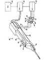
この発明は、体内から組織部分を採取するための生検装置に関係するものであり、特に、コア生検装置内での切断器具の速度の制御に関係するものである。コア生検装置の例は、ヒブナーらに発行された特許文献5に記述されており、この文献は参照によってこの明細書に組み込まれる。図1は、符号20によって概ね確認されるハンドピースと、減圧システム22と、制御ユニット24と、電源26を含むこの発明によるコア採取用生検器具を示している。ハンドピース20は、操作者の手によって容易に操作されるのに好適な軽量で人間工学的な形状を有している。ハンドピース20は、プローブアセンブリ28と、着脱可能に連結されるホルスター30を含む。 The present invention relates to a biopsy device for collecting a tissue portion from the body, and more particularly to controlling the speed of a cutting instrument within a core biopsy device. An example of a core biopsy device is described in U.S. Patent No. 6,057,049 issued to Hibner et al., Which is incorporated herein by reference. FIG. 1 shows a core collection biopsy instrument according to the present invention including a handpiece generally identified by the
プローブアセンブリ28は、第1減圧チューブ32および第2減圧チューブ34によって減圧システム22に連結されている。第1減圧チューブ32および第2減圧チューブ34は、それぞれ、第1コネクタ36および第2コネクタ38によって減圧システム22に着脱可能に連結されている。第1コネクタ36は、雄部40と、第1減圧チューブ32に取り付けられた雌部42を有している。第2コネクタ38は、雌部44と、第2減圧チューブ34に取り付けられた雄部46を有している。コネクタとしての雄部40、雌部42、雌部44および雄部46は、第1減圧チューブ32および第2減圧チューブ34の減圧システム22への偶発的な切換えを防止する上記方法で取り付けられている。ホルスター30は、ハンドピース20を制御ユニット24および電源26に対して作用可能に連結する制御コード48を含む。制御コード48は、ハンドピース20に対して電力および制御情報を与えるものである。 The
ハンドピース20が電気機械的アームではなく操作者の手によって操作されるので、操作者は、大きな自由度で、ハンドピース20の先端を対象の組織の塊に向けることが可能である。外科医は、操作中に触覚的なフィードバックを受け取り、これにより十分な程度、直面した組織の密度および硬度を確認することができる。さらに、ハンドピース20は、電気機械的アームに実装された器具を用いて採取される場合よりも、胸壁に近い部分の組織を採取するために、患者の胸壁に対して略平行に保持されてもよい。この技術分野における当業者は、万一、立体X線テーブルを使用することが望ましい場合には、立体X線テーブルの可動アームにハンドピース20を確実に保持するために、支持台あるいは「ネスト」が備えられることができるものと正当に評価する場合がある。 Since the
図2は、ホルスター30から取り外されたプローブアセンブリ28を示している。プローブアセンブリ28は、上部ケース50と、下部ケース52を含み、各ケースは、ポリカーボネート等の剛性で生体適合性を有するプラスチックから射出成形されてもよい。プローブアセンブリ28の最終組立時においては、上部ケース50および下部ケース52は、超音波溶着、スナップファスナー、締り嵌めおよび接着を含むが、これらに限定されないプラスチック接合用に多くの周知の方法のいずれかによって、接合縁部54に沿って互いに接合可能である。同様に、ホルスター30は、ポリカーボネート等の剛性で生体適合性を有するプラスチックから射出成形され、プラスチック部分を接合するための任意の適切な方法によって縁部60に沿って互いに接合されてもよい上部ケース56および下部ケース58を含む。 FIG. 2 shows the
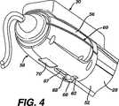
図3および図4は、ホルスター30の底部およびプローブの下部ケース52を示している。これらの図面に示されているように、プローブラッチ62は、プローブアセンブリ28をホルスター30に着脱可能に連結するためにプローブの下部ケース52内に向けて成形されている。プローブラッチ62は、片持ち梁であり、ラッチ傾斜面64に印加される力によって下方に撓み可能である。プローブラッチ62は、プローブアセンブリ28の近位端がホルスター30内に挿入されるときにホルスタースロット67内に挿入されるラッチ突出部66をさらに含む。ラッチ傾斜面64は、この傾斜面64とホルスター30のケースの内面65との間の相互作用によって下方に撓ませられている。プローブラッチ62は、プローブアセンブリ28が完全にホルスター30内に挿入されたときに、スロットキー68内に保持可能に嵌められる。ホルスター30からプローブアセンブリ28を取り外すために、操作者は、傾斜面64がスロットキー68から脱するまで、ラッチ突出部66を手動的に押し下げる。ラッチ突出部66は、その後に、プローブアセンブリ28およびホルスター30が分離されるまで、ホルスタースロット67を経由して軸方向に引かれてもよい。 3 and 4 show the bottom of the
ここで図1および図2に戻ると、これらの図面には、操作者が片手でハンドピース20を使用できるようにホルスター30の上部ケース56上に設けられた電気スイッチが示されている。これらの電気スイッチは、カッターの動作(例えば、組織を採取するために前方(遠位側)へカッターを移動させるロッカースイッチ72の前方移動と、サンプル取得面74内に組織サンプルを位置決めするために逆方向(近位側)へカッターを駆動するロッカースイッチ72の後方移動)を駆動するための2ポジションロッカースイッチ72と、減圧システム22を駆動するための減圧スイッチ76を含めることができる。片手手動操作は、操作者の他方の手が自由になり、例えば超音波イメージング装置を保持することを可能にする。ホルスター30の遠位端上の隆起78は、操作者がハンドピース20を掴みかつロッカースイッチ72および減圧スイッチ76を操作するのを支援するために設けられている。プローブアセンブリ28のケース50および52も、使用中に、上記器具上の操作者の握りを改善するような輪郭に形成されてもよい。 Returning now to FIGS. 1 and 2, these drawings show an electrical switch provided on the
第1減圧チューブ32および第2減圧チューブ34は、シリコン配管、ポリ塩化ビニル配管あるいはポリエチレン配管等の可撓性、透明性あるいは半透明性の材料から構成可能である。この材料は、第1減圧チューブ32および第2減圧チューブ34を経由して流れる物質を視覚化することを可能にする。図3および図4に示されているように、例えば符号70によって示されるような1つまたはそれ以上のスロットは、第1減圧チューブ32および第2減圧チューブ34に間隙を与えるようにホルスター30の下部ケース58内に具備可能である。プローブアセンブリ28の遠位端にある開口領域は、サンプル取得面74へのアクセスを可能にする。操作者あるいは補助者は、サンプル取得面74から組織サンプルを取得することができる。 The
図5は、プローブアセンブリ28を分解して示す投影図を与える。組織サンプルを採取するために外科患者の皮膚内に挿入される穿孔具(外カニューレ)80を含む生検針は、プローブアセンブリ28の遠位端に配置されている。穿孔具80は、長尺で金属製の穿孔チューブ82を有するカニューレと、上記チューブの軸方向長さに沿って延在し、上記カニューレに関連した管腔84を含む。穿孔チューブ82の遠位端の近傍には、外科患者から取得されるべき組織を受け取るための側方の組織受容ポート86が設けられている。穿孔チューブ82の傍らには、減圧管腔90を有する長尺の減圧チューブ88が接合されている。穿孔チューブ82は、金属あるいはプラスチックを含む任意の適切な材料で形成可能であり、穿孔用の管腔84に接合されるか、あるいはこの穿孔用の管腔84と一緒に形成可能である。図6に示されているように、穿孔用の管腔84は、ポート86によって規定される組織用穴の底部に配された複数の減圧穴92を介して減圧管腔90と流体的に連通している。これらの減圧穴92は、流体を排除するのに十分に小さいが、減圧88の減圧管腔に対して流体的に連結されている第1減圧チューブ32を経由して切除された組織部分が除去されるのに十分な大きさではない。穿孔具80の鋭利な先端は、穿孔具80の遠位端に取り付けられた分離穿孔用末端具94によって形成可能である。末端具94は2つの側面、すなわち、平坦形状部分と外科患者の組織に対して穿孔するのに適した他の形状部分を有している。 FIG. 5 provides an exploded view showing
穿孔具80の近位端は、長穴98が貫通する結合スリーブ96に取り付けられており、長穴98の幅広の中央部分の中には、横方向に形成された開口部102が形成されている。長尺で金属製の管状カッター104は、このカッターが遠位および近位の両方向に容易に摺動できるように、結合スリーブ96の長穴98および穿孔具80の穿孔用の管腔84に対して軸方向に一列に整列されている。カッターガイド106は、結合スリーブ96の近位端に配されている。カッターガイド106は、カッター104と結合スリーブ96との間で適切な整列を保証する金属製の漏斗形状ガイドの形態を採ることができる。結合スリーブ96およびカッターガイド106は、下部ケース52から延在する一体形成型の支持リブ107および上部ケース50の遠位端に設けられた一体形成型のハウジング108によって、プローブの上部ケース50と下部ケース52との間に支持されている。これらの一体形成型の支持リブ107およびハウジング108は、プローブの上部ケース50および下部ケース52に形成されたスロット110および開口部112と一緒に、カッターが遠位および近位の両方向に容易に平行移動できるように、カッター104と結合スリーブ96との間での適切な整列を保証するものである。第1減圧チューブ32の遠位端は、結合スリーブ96の横方向に形成された開口部102に堅く挿入する重合体製の減圧用取付け具113に取り付けられている。開口部102は、管腔90と流体的に連通しており、穿孔用の管腔84が減圧穴92を介して減圧システム22内の減圧容器と流体的に連通することを可能にする。 The proximal end of the piercing
カッター管腔114は、実質的にカッター104の全長を通り抜けて延在している。長尺で中空管状の組織除去器115は、カッター104が組織除去器115の長さに沿って平行移動できるように、上記カッター管腔114内に同軸的に配設可能である。組織除去器115は金属製あるいは非金属製であってもよい。第2減圧チューブ34は、組織除去器115を通過して延在する中央通路を経てカッター管腔114に減圧を与えるために、組織除去器115の近位端に流体的に取り付け可能である。第2減圧チューブ34は、第1減圧チューブ32の横に並んで、開口部117から下部ケース52を出る。ストレーナ119は、組織断片が組織除去器115を通過して減圧システム22に入るのを防止するために、組織除去器115の遠位端に取り付けられている。 The
上記組織除去器115は、下部ケース52に対して固定的に保持されかつプローブの下部ケース52の内部上に設けられた一対の近位支持部(図示せず)によって支持されることが可能である。第2減圧チューブ34は中空の組織除去器115を経てカッター管腔114を通じて減圧を与えるものであり、この減圧は、カッター104の遠位端が組織受容ポート86の近位側に位置決めされたときに、組織受容ポート86内への組織の吸引を支援するのに使用可能である。 The
カッター104の遠位端は鋭利になってカッター刃116を形成しており、このカッター刃116はカッター104が回転する際に、カッター刃116に抵抗して保持された組織を切断するためのものである。カッター104の近位端は、カッターギア118の軸穴内に取り付けられている。カッターギア118は、金属製あるいは重合体製であってもよく、複数のカッターギア歯120を含む。各カッターギア歯120は、この技術分野において周知であるような典型的な平歯車の構成を有している。 The distal end of the
図5および図6を参照すると、カッターギア118は、カッターギア歯120と噛合するように設計された複数の駆動ギア歯124を有する長尺の回転駆動シャフト122によって駆動される。この実施の形態では、駆動ギア歯124は、駆動シャフト122の略全長に沿って延在しており、カッター104の平行移動中ずっと、カッターギア歯120と係合している。駆動ギア歯124は、駆動シャフト122が回転駆動しているときはいつでもカッター104を回転させるために、カッターギア歯120と連続的な係合状態にある。以下に詳述されるように、駆動シャフト122は、カッターが組織を切断するために組織受容ポート86を通じて遠位側へ前進する際に、カッター104を回転させる。駆動シャフト122は、液晶ポリマー材料等の剛性エンジニアリングプラスチックから射出成形されてもよく、あるいはこれに代えて、金属あるいは非金属材料から製造可能である。また、駆動シャフト122はアルミニウムから押出成形あるいは金属材料から機械加工可能である。 With reference to FIGS. 5 and 6, the
図7に示されているように、駆動シャフト122はこのシャフトの遠位側へ延在する第1軸方向端部126を含む。第1軸方向端部126は、プローブケースの内部上に成形された駆動シャフトインターフェース127によってプローブの下部ケース52内での回転に対応している。同様に、第2軸方向端部128は、回転駆動シャフト122の近位側へ延在しており、プローブの下部ケース52の内部上にも成形された他のインターフェース130で支持されている。Oリング131およびブッシュ133は、回転駆動シャフト122がプローブの下部ケース52内に配されているときに、上記インターフェース127および130内に置かれるように各軸方向端部126および128上に設けられてもよい。ブッシュ133は、Oリング131がプローブアセンブリ28の架台から回転駆動シャフト122の振動を切り離している間、回転シャフトインターフェース127および130における摩擦を低減する。また、ブッシュ133は、回転シャフトインターフェース127および130において、Oリング131なしで、使用可能である。駆動スロット132は、第1軸方向端部128内に形成されている。以下にさらに詳述されるように、駆動スロット132は、これに対応しモータ駆動シャフト134内に形成された駆動スロット、あるいは上記駆動シャフトに回転を与える他の回転駆動入力部と接続している。 As shown in FIG. 7, the
ここで、図8および図9を参照すると、カムナット136は、カッターギア118を保持すると共に、カムナット136の遠位側および近位側の両方向への平行移動中にカッターギア118および取り付けられたカッター104を搬送するために、プローブアセンブリ28内に設けられている。カムナット136は、好ましくは剛性ポリマーから成形され、かつ軸方向に延在する円筒状の穴138を有している。一対のJ字状のフック延長部140は、カムナット136の一側部から延在している。一対のフック延長部140は、カムナット136の遠位側および近位側の両方向への平行移動中に、カッターギア118およびカッター104に近位側および遠位側への平行移動を与えるために、カッターギア118の両側部上にカッター104を回転可能に支持している。フック延長部140は、カッターギア歯120が駆動ギア歯124と噛合する適切な方向に、カッター104およびカッターギア118を一列に整列させる。 Referring now to FIGS. 8 and 9, the
カムナット136は、平行移動シャフト(可変ピッチ部材)142に沿って平行移動するためのシャフト142上に支持されている。シャフト142は、カッター104および回転駆動シャフト122と平行な状態で、カムナットの穴138を通じて延在している。平行移動シャフト142は、アルミニウムあるいはこれと同様の他の材料から構成可能であり、シャフト142の外周部に機械加工可能であるか、あるいは他の方法で形成可能である主ネジ溝144の形態を採る通路等の通路を含めることができる。主ネジ溝144は、概ね螺旋状とすることができる。主ネジ溝144のピッチは、平行移動シャフト142の近位端と遠位端との間で変えてもよい。この明細書で記述された実施の形態では、主ネジ部のピッチは、粗い、すなわち上記シャフト142の近位部分における広い間隔のピッチから、細かい、すなわち上記シャフト142の遠位部分における狭い間隔のピッチまで変化している。ネジ部のピッチの特定ピッチ幅、並びに平行移動シャフト142の長さに沿う狭いピッチに対する広いピッチの比は、カッター104の所望の操作に依存して、この発明において変更することになる。 The
図面において、平行移動シャフト142は、時計回りの回転(近位方向から遠位方向へ向く)がカムナット136を近位方向にシャフト142に沿って平行移動させるが、これに対して、シャフト142の逆回転がカムナット136を遠位方向に移動させるように、右回りネジで示されている。しかしながら、ネジ方向は、用途および回転駆動入力部に依存するネジ部の特定方向となるように、逆にすることができる。 In the drawing, the
図10Aおよび図10Bに非常に詳細に示されているように、カムナット136は、穴138に対して直交する方向に延在する受容穴150を含むように、成形、機械加工あるいは他の方法で形成されている。カムフォロアピン152は、ネジ部が穴138を通過する際に、上記ピンの一部がカムナット136を越えて延在し、かつ平行移動シャフト142の主ネジ溝144内に延在するように、受容穴150内で位置決めされている。主ネジ溝144は、平行移動シャフト142が回転する際に、シャフト142の表面回りでカムフォロアピン152を案内する通路を形成している。カムフォロアピン152は、カムナット136と平行移動シャフト142との間のインターフェースを形成するようにカムナット136の一部として組み立てられる金属製で、機械加工されたピンとすることができる。図示された実施の形態では、カムフォロアピン152は、カムナットの受容穴150に嵌合するインターフェースで組み立てられている。これに代えて、カムフォロアピン152は、インサート成形あるいはネジによるなど、他の方法によって挿入可能である。他の実施の形態では、カムフォロアピン152は、主ネジ溝144内で半径方向に移動できる「フロート」となるようにカムナット136上に支持可能である。 As shown in greater detail in FIGS. 10A and 10B, the
図10Bに示されているように、カムフォロアピン152は、カムナットの受容穴150内に置かれ、カム通路(主ネジ溝)144のプロファイルに適合するように形成された傾斜面156によって示されているようなテーパー形状あるいは他の形状の先端を有することができる。カム通路144は、テーパー状のプロファイルを有している。傾斜面156は、カムフォロアピン152が主ネジ溝144によって形成されたテーパー状の通路内を自由に摺動することを可能にし、主ネジ溝144のネジピッチおよび/または幅の容易な変更に適応することを可能にする。 As shown in FIG. 10B, the
図8および図9を参照すると、スロット158は、図15に示されたモータシャフト160等の駆動モータシャフトに平行移動シャフト142を取り付けるためにシャフト142の近位端に設けられている。モータシャフト160は、このシャフト端部162とスロット158との係合を通じて平行移動シャフト142に回転を与える。平行移動シャフト142は、カム通路(主ネジ溝)144とカムフォロアピン152との間のインターフェースにより、可変ピッチのカム通路144に追従するカムナット136を回転させる。したがって、カムナット136は、シャフト142が回転する際に、シャフト142の長さに沿って平行移動する。カムナット136が平行移動シャフト142の回転によって遠位側へ平行移動する際に、カッターギア118はフック延長部140によって前方(遠位側)へ押圧される。カッターギア118は、カムナット136の平行移動と同一方向および同一速度でカッター104を移動させるために、カッター104にしっかりと取り付けられている。平行移動シャフト142がカムナット136内で回転する際に、円筒状の穴138は、カムナットが平行移動シャフト142を横切る際に、カムナットを安定化させるブッシュを兼ねている。 With reference to FIGS. 8 and 9, a
この発明の生検装置の操作中に、カッター104は、サンプル取得面74に非常に近い完全に後退した位置と組織受容ポート86に非常に遠い完全に配設された位置との間のいずれかの方向で平行移動する。図示された実施の形態では、カッター104は、完全後退位置から完全配設位置までの約6インチ(1インチ=約2.54cm)の距離を平行移動することができる。カッターの平行移動の距離に沿う確認可能な複数の中間位置が存在している。カッター104の遠位端116が上記各位置に到達するときに、所望ならば、カッターの回転速度(しばしば単に回転速度という)あるいはカッターの平行移動速度(しばしば単に平行移動速度という)のいずれかあるいは双方に対する調節が可能である。 During operation of the biopsy device of the present invention, the
この明細書に記述された生検装置の実施の形態に関し、カッターの平行移動の距離に沿って4つの位置が確認可能である。これらの位置ごとに、カッターの回転および/または平行移動の速度に対する調節が可能である。これらの速度の変化は、機械的に、あるいはモータ速度の変更のいずれかの異なる方法で、生検装置内で達成可能である。カッター位置の記述を容易にするために、カッター位置は、カッター104の遠位端上のカッター刃116の実際の位置として理解されるべきである。これらの4つのカッター位置は、次の4つがある:カッター104がサンプル取得面74に非常に近い第1の位置;カッター104がサンプル取得面74に非常に遠い第2の位置;カッター104が組織受容ポート86に非常に近い第3の位置;カッター104が組織受容ポート86に非常に遠い第4の位置。これらの4つの位置は、しばしば位置1、位置2、位置3および位置4と呼ばれる。これらの4つのカッター位置は、例示の目的のみで与えられ、多くの他のカッター位置は、この発明の範囲を逸脱することなく、カッターの回転速度および/平行移動速度に対する調節を知らせるために、この発明において使用されてもよい。 For the biopsy device embodiment described in this specification, four positions can be identified along the distance of the cutter translation. For each of these positions, adjustments to the speed of rotation and / or translation of the cutter are possible. These speed changes can be achieved in the biopsy device either differently, either mechanically or by changing the motor speed. To facilitate the description of the cutter position, the cutter position should be understood as the actual position of the
図5、図6および図9に示された実施の形態では、カッター104が平行移動距離に沿って位置1から位置2への平行移動する際には、カムフォロアピン152は、主ネジ溝144の粗いピッチ部分146を横切り、これによりカッター104が平行移動シャフト142の回転ごとに、より速い速度で平行移動することができる。カッター104が位置2から位置3へ移動する際には、カムの主ネジ溝144が粗いピッチ幅から細かいピッチ幅へ移行し、これによりカッター104が平行移動シャフト142の回転ごとに、より遅い速度で平行移動することができる。カッター104が位置3に到達する際には、駆動シャフト122は、カッターの回転に呼応して回転し始める。したがって、カッター104は、カムフォロアピン152がカムの主ネジ溝144のより遅く、細かいピッチ部分148を横切り始めるときに、回転し始める。カッター104の平行移動速度は、組織の切断中に、組織受容ポート86を通じて回転するカッター104をより遅く前進させる細かいピッチ部分148で減速される。組織受容ポート86を通じた平行移動(位置3と位置4との間)中に、カッター104は、所望の組織切断速度で駆動シャフト122によって回転させられる。 In the embodiment shown in FIGS. 5, 6, and 9, when the
カムの主ネジ溝144のピッチ幅は、平行移動シャフト142の360°回転ごとに、カムナット136による直線移動距離を決定する。主ネジ溝144のピッチ幅が広ければ広いほど、シャフト142の360°回転ごとに、カッター104による直線移動距離が大きくなる。したがって、カッター104の直線速度は、平行移動シャフト142上のカムナット136の位置関数として変更可能である。主ネジ溝144のピッチは、平行移動シャフト142の回転速度に対するカッターの平行移動速度の所望の比を与えるように選択可能である。主ネジ溝144は、可変ピッチカムの通路として機能することができる。 The pitch width of the
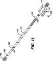
図9および図11は、平行移動シャフト142の全範囲並びに可変ピッチの主ネジ溝144を示している。これらの図面に示されているように、平行移動シャフト142は、このシャフト142の回転にかかわらず、カッター104の平行移動が妨げられるような、上記シャフト142の近位端および遠位端に近傍の領域を含めてもよい。符号164で示された上記領域では、主ネジ溝144は、零のピッチ幅を有してもよく、これによりシャフト142の外周回りに360°の溝を形成することになる。360°溝、すなわち零ピッチ領域164は、平行移動シャフト142に沿うカムナット136の移動を阻害する。主ネジ溝144が零ピッチ領域164へ移行する際には、平行移動シャフト142の外径は166で示されているように減らされ、主ネジ溝144のピッチは、カムフォロアピン152およびカッター104の平行移動を遅くするように、より細かくなっている。 9 and 11 show the entire range of the
カムナット136が零ピッチ領域164に入るときには、シャフト142は回転し続けてもよいが、カムナット136は、零ピッチ領域164内にカムフォロアピン152が保持されているために、シャフト142に沿う平行移動が妨げられる。カッター104が移動行程の最も遠位(あるいは最も近位)点にあり、シャフト142の回転方向が逆(ロッカースイッチ72を押し下げることなどによって)になっているときには、カムフォロアピン152は、可変ピッチの主ネジ溝144と係合する状態に零ピッチ領域164から戻るように付勢されることになる。図11に示されているように、コイルスプリング168および170等の付勢装置は、シャフト142の回転方向を逆転させるときに、平行移動方向を変更する場合には、可変ピッチの主ネジ溝144と係合する状態に戻るようにカムナット136を付勢するために、平行移動シャフト142の各端部近傍に設けられてもよい。零ピッチ領域164におけるシャフト142の外径を減少させることおよび主ネジ溝144のピッチをより細かくすることは、カムフォロアピン152が零ピッチ領域164の溝内を進む際に、カムフォロアピン152の騒音あるいは振動を低減させるのにも有利となる。 When the
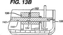
図12Aおよび図12Bは、カムナット136がシャフト142の近位端に向けて平行移動する際における零ピッチ領域164およびコイルスプリング168を示している。図13Aおよび図13Bは、カムナット136が最も近位位置(すなわちカッターの位置1)へ平行移動した後におけるカムナット136を示している。この位置1では、カムフォロアピン152は零ピッチ領域164に係合しており、コイルスプリング168はカムナット136に対して圧縮されている。カムナット136は、零ピッチ領域164に係合しているカムフォロアピン152のために、シャフト142が回転する際には、上記位置に留まる。一旦、モータ回転方向を変更するなどによって、シャフト142の回転方向が逆転すると、コイルスプリング168内に保存されたエネルギは、零ピッチ領域164外へ(カムフォロアピン152を経由して)カムナット136を押し出すように、カムナット136に対して作用する。コイルスプリング168は、カムナット136(およびカッター104)が反対方向へ平行移動し始めるように、主ネジ溝144に対応する可変ピッチの通路と係合する状態に戻るようにカムナット136を押圧する。 12A and 12B show the zero
シャフト142の外径は、機械加工あるいは他の方法で減少可能であり、主ネジ溝144のネジ(例えばテーパー状の壁部を有する)をより狭い間隔にすることで細かいピッチ(インチごとのネジ部が増える)を与えることになる。代替の実施の形態では、テーパー状のネジ壁部を有するカム通路(主ネジ溝)144のネジ深さは、カムフォロアピン152の平行移動速度を変更するために、変更可能である。例えば、カム通路(主ネジ溝)144の深さは、シャフト142の外径が一定に維持されるのに対して、シャフト142上により狭く配されるべきネジ部を可能にするために短くされてもよい。より間隔を狭くしたネジ部は、平行移動シャフト142の各回転中に、カッター104によって移動する直線距離を縮小する。 The outer diameter of the
図14Aから図14Cは、先の図1から図13に具体化されているようにこの発明の操作中に、カッター104の4つの位置のうち、3つを描写している。カッター104の3つの位置は、カッター104の遠位端上の(カッター104と共に移動する)カムナット136およびカッター刃116の相対的な位置を観察することによって、最も容易に識別される。図14Aは、カッター104が位置1に位置決めされているプローブアセンブリ28を部分断面視した上面図を示している。この位置1では、カッター104は、カッター刃116がサンプル取得面74の近位側に位置決めされた状態で、完全に後退した位置にある。カムナット136は、カムフォロアピン152がカム通路(主ネジ溝)144の零ピッチ領域164内で回転している状態で、平行移動用シャフト142の近位端に位置決めされている。コイルスプリング168は、カムナット136の近位端に対して圧縮されている。図14Aに示された位置では、カッター104は、穿孔具80内の組織受容ポート86が組織を受容するために開けられるように、完全に後退した位置にある。この位置では、組織サンプルは、サンプル取得面74から取得されてもよい。 14A-14C depict three of the four positions of the
図14Bは、カッター刃116が組織受容ポート86の直近にある位置3に向けて前進したカッター104を示している。この位置3では、カムナット136は、カムフォロアピン152が主ネジ溝144の幅広の粗いピッチ部分146から細かいピッチ部分148へ平行移動している1点に向けて、シャフト142に沿って平行移動している。同様に、カッター104は、駆動シャフト122がカッターギア歯120および駆動ギア歯124を介してカッター104を回転させている中間位置へ前進している。カッター刃116は、組織受容ポート86に直近の位置に配されている。組織受容ポート86における減圧穴92は、第1減圧チューブ32が減圧システム22に対して流体的に連結されているときに、組織受容ポート86に隣接した軟組織が組織受容ポート86内に吸引されるように、開けられている。 FIG. 14B shows the
図14Cは、カッター104が最も延長した位置にあると共にカッター刃116が組織受容ポート86の遠位側にある位置4へ前進したカッター104を示している。この位置4では、カッター104は、回転駆動シャフト122によって適切な切断速度で回転させられている。減圧穴92を経由した減圧によって組織受容ポート86内へ吸引された組織は、回転しながら前進するカッター刃116によって切断されて、カッター管腔114内に保存される。カッター104が図14Aに示された位置1まで後退したときに、組織除去器115は、サンプル取得面74まで組織サンプルを引き戻す。図14Cには、カム通路(主ネジ溝)144の細かいピッチ部分を通って平行移動して、最も遠位位置にあるカムナット136が示されている。この位置では、カムフォロアピン152は、可変ピッチのカムスロットとしてのカム通路(主ネジ溝)144の遠位端における零ピッチ領域164に係合している。コイルスプリング170は、一旦、平行移動シャフト142の回転方向が反転すると、カム通路(主ネジ溝)144の細かいピッチ部分148と係合する後方位置にカムナット136を付勢するために、カムナット136によって圧縮され、カッター104は位置1まで戻される。 FIG. 14C shows the
図15は、ホルスター30の第1の実施の形態を分解して示す投影図である。この実施の形態では、ホルスター30は、2つのモータがプローブアセンブリ28内の回転駆動シャフト122および142に支持されている一体電動式のホルスターである。上述したように、ホルスター30は、この明細書で開示された上記2つのモータおよびモータ駆動シャフトを収容するように、図15および図16に示された形状とされる上部ケース56と下部ケース58を含む。最終組立時には、上部ケース56および下部ケース58は、複数の整列穴182に留めつけられるネジ180によって互いに接合されるか、あるいはこの技術分野において周知の他のタイプのファスナーによって互いに取り付けられる。 FIG. 15 is an exploded projection view of the
一対のモータ駆動シャフト134および160は、ホルスター30の封入された近位部分内に収容されている。第1の駆動シャフト134は、回転駆動シャフト122のスロット132に対して作用可能に係合するように形成された遠位端172を有している。第2の駆動シャフト160は、平行移動シャフト142のスロット158に対して作用可能に係合するように形成された遠位端162を有している。モータ駆動シャフト134および160は、プローブアセンブリ28およびホルスター30が連結されたときに、駆動シャフト122および平行移動シャフト142と係合するギアケース184から遠位側へ延在している。第1の駆動モータ186および第2の駆動モータ188は、ギアケース184上に設けられている。第1の駆動モータ186は、図16に示されたギアアセンブリ190を介して駆動シャフト134に対して回転運動を与える。駆動シャフト134に生じる回転運動は、プローブアセンブリ28およびホルスター30が連結されたときに、遠位端172およびスロット132を経て、回転駆動シャフト122に伝達される。同様に、第2の駆動モータ188は、第2のギアアセンブリ192を介して駆動シャフト160に対して回転運動を与える。駆動シャフト160の回転運動は、スロット158と駆動シャフト160の遠位端162との係合によって平行移動シャフト142に伝達される。駆動モータ186および188は、スイス国サヒゼイン(Sachsein)のマキソン精密モータ社(Maxon Precision Motors)から入手可能な型式118718の4.5ワットモータ等の直流グラファイトブッシュモータとすることができる。駆動モータ186は、マキソン精密モータ社から入手可能な型式118184の遊星歯車の使用が可能であり、駆動モータ188は、マキソン精密モータ社から入手可能な型式110322の遊星歯車の使用が可能である。 A pair of
図16および図17を参照すると、第1ギアアセンブリ190および第2ギアアセンブリ192は、駆動モータ186および188と駆動シャフト134および160の近位端に位置決めされ、いずれのアセンブリもベルトによって連係した一対のギアから構成されている。駆動モータ186および188と駆動シャフト134および160との連結の解除は、追加のギアの必要なしに、駆動シャフト134および160が異なる期間および異なる速度で単独駆動を可能にする。さらに、個々の駆動モータが駆動シャフト134および160に使用されるので、駆動モータは、組み合わせて両シャフトを駆動するのに必要なモータよりも小型で低出力であってもよい。 Referring to FIGS. 16 and 17, the
駆動モータ186および188は、例えば、ホルスター30の下部ケース58に成形された1つまたはそれ以上の支持部196によるなどして、任意の便利な方法でホルスター30内に支持可能である。配電盤198は、ホルスター30内に設けられ、かつ任意の便利な方法で駆動モータ186および188と電気的に接続されている。また、配電盤198は、ロッカースイッチ72および減圧スイッチ76等の種々のユーザー接続スイッチ並びに、制御ユニット24からの電力および信号をホルスター30に与える制御コード48と接続可能である。重合性ゴムあるいは他の適切な封止材料から構成されるスイッチシール200および202は、流体がホルスター30に入りかつ配電盤198に悪影響を及ぼすことを防止するために、配電盤198とこれと隣接する構成要素との間に配されている。金属板204は、ホルスター30内に構造支持部を設け、および/またはホルスター30のプローブアセンブリ28への固定を容易にする実装あるいは連結の態様を有することができる。 Drive
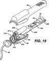
図15から図17に示された実施の形態は、ギアケース184上に設けられ、かつモータ駆動シャフト134および160のそれぞれを単独で駆動するためにモータ駆動シャフト134および160に直接、連結された2つの一体型のモータを含む。図18から図20に示されたような代替の実施の形態では、単独の一体型のモータは、適切なギアを経て回転駆動シャフトおよび平行移動シャフトの双方を駆動するのに使用可能である。この実施の形態では、単独のモータ208は、ギアケース184およびホルスター30の近位端におけるモータ駆動シャフト134および160上に設けられてもよい。モータ208は、ギアアセンブリ210を経て駆動シャフト134および160に対して作用可能に連結されている。図19および図20は、モータ208とギアアセンブリ210とが連結された状態で、単独のモータアセンブリの後部を示している。この連結はモータシャフト216のギア214と駆動シャフト134のギア218との間を延在する単独のベルト212を含む。図20に示されているように、追加ギア220は、回転駆動シャフト134の回転から平行移動シャフト160を駆動するために、ギアケース184内に収容されている。追加のギア220は、平行移動駆動シャフト160が回転駆動シャフト134よりも遅い速度で回転することを可能にするために、2つの駆動シャフト134および160間にギア減速を与える。また、ギア220は、平行移動駆動シャフト160が回転駆動シャフト134よりも速い速度で回転することを可能にするように、あるいは、カッター104の所望の操作に依存して2つの駆動シャフトが同一速度で回転するのを可能にするように、構成可能である。上述した2つの実施の形態に加えて、この発明は、ホルスター30の側部あるいは底部に沿って、あるいはホルスター30の前端において、ギアケース184後方のホルスター30の近位端に位置決めされた1つまたはそれ以上の一体型のモータを含めることができる。さらに、1つまたはそれ以上の駆動モータは、ホルスター30の外部に配設され、かつ1つまたはそれ以上の回転可能なシャフトによって回転駆動シャフト122および平行移動駆動シャフト142に対して作用可能に連結されている。したがって、この発明における上記モータの特定配置は、ホルスター30の所望の寸法あるいは重量分布に依存して、変更可能である。 The embodiment shown in FIGS. 15-17 is provided on the
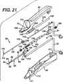
図21および図22は、この発明の第2の単独モータの実施の形態に使用されるプローブアセンブリ28を示している。この単独モータの実施の形態では、回転駆動シャフト134および平行移動駆動シャフト160は、ギア214、218およびベルト212を作動する共通のモータ208が同時に上記2つのシャフトを駆動するので、この生検装置の全操作中に回転させられる。モータ駆動シャフト134の連続回転に対応するために、第1の実施の形態の回転駆動シャフト122は、上記駆動シャフトの遠位端に最も近い位置に配された駆動ギア歯224を有する改造駆動シャフト222に置き換えられる。この位置におけるギア歯224では、カッター104が組織受容ポート86に非常に近い位置に向けて遠位側へ前進した後だけ、カッターギア118は、改造駆動シャフト222と係合する。カッターギア118が駆動ギア歯224と係合するときには、ギア歯120および224は噛合し、カッター104は駆動シャフト222によって回転させられる。駆動ギア歯224は、この駆動ギア歯224の近位端に成形された引込み傾斜路254を含めることができる。傾斜路254は、ギアの円滑な噛合を与えるために、駆動ギア歯224と係合するギア歯120へ移行する。駆動シャフト222は、カッター104が組織切断段階のカッター前進中にだけ回転するように、この単独モータの実施の形態用の方法で改造されている。 21 and 22 show a
図23は、減圧システム22をより詳細に示している。図23に示されているように、減圧システム22は、第1コネクタ36の雄部40に対して第1減圧チューブ232によって連結された第1バルブ230を含む。第2バルブ234は、第2コネクタ38の雌部44に対して第2減圧チューブ236によって連結されている。第1バルブ230および第2バルブ234は、側方の第1減圧チューブ32および軸方向の第2減圧チューブ34に対するそれぞれの減圧供給を制御する。第1バルブ230および第2バルブ234は、生検装置20の操作中に、減圧チューブ232および236を開閉するための制御ユニット24からの信号によって制御されるソレノイドを含む。減圧チューブ232および236のそれぞれは、運転サイクル中に、異なる間隔で別々に開閉されてもよい。減圧チューブ232および236は、減圧タンク240等の流体タンクに向けて第1バルブ230および第2バルブ234から延在している。主要な減圧チューブ242は、モータ246によって駆動され、符号244によって示された減圧ポンプおよび容器に減圧タンク240を取り付ける。減圧ポンプ244は、例えばピストン、ダイアフラム、ロータリーすなわち回転弁ポンプ等の種々のタイプであってもよい。モータ246は、例えばブラシレス直流モータ等の可変速度で操作可能なタイプであることが好ましい。モータ速度は、減圧タンク240内の減圧レベル等、流体タンク中で検知された圧力に基づいて制御可能である。また、モータ速度は、所望の切断位置の予定等、運転サイクル中に減圧に関する予想された必要性に基づいて、制御されてもよい。 FIG. 23 shows the vacuum system 22 in more detail. As shown in FIG. 23, the decompression system 22 includes a
マフラー・バッフルシステム256および排気ポート258は、騒音を低減しかつシステムを換気するために、減圧ポンプ244から延在している。追加の減圧チューブ248は、減圧タンク240から減圧センサ250へ延在している。減圧センサ250は、減圧タンク240内の減圧をモニターし、かつ圧力信号252を制御ユニット24へ周期的に送信する。制御ユニット24は、減圧センサ250からの圧力信号252に関してモータ246を制御するためのマイクロプロセッサすなわちマイクロコントローラ254を備えたプリント回路基板(PCB)を含む。 A
1つの実施の形態では、マイクロコントローラ254は、減圧センサ250からの圧力信号252に関してモータ246の速度を調節することによって減圧タンク240内の均一で所望の減圧を維持する。モータ速度は、モータの電流、電圧あるいはトルクを変更することによって調節され、これにより減圧ポンプ速度の変更および/または減圧ポンプの電源のオン・オフを行ってもよい。1つの実施の形態では、減圧タンク240内の圧力が所望の予定レベルにある間は、マイクロコントローラ254は、減圧ポンプ244が減圧システム22内で余分な減圧(および騒音)を生じる操作をしないようにモータ246を無負荷運転する。バルブ230および234の一方または両方が開いている場合など、減圧センサ250からの圧力信号252が減圧タンク240内で圧力低下を示す場合には、マイクロコントローラ254は、モータ246を作動して、減圧タンク240内の圧力が再び所望レベルに到達するまで、減圧ポンプ244をつける。これにより、減圧センサ250は、減圧システム22に対して閉ループ制御を与えて、減圧ポンプ244を連続運転することもなく、減圧システム22内の所望の圧力を維持することができる。代替の実施の形態では、マイクロコントローラ254は、生検装置20の運転サイクル中に予想減圧に基づいて減圧ポンプ244を運転するためにモータ246を駆動する。マイクロコントローラ254は、運転サイクルにおいて異なる位置で減圧ポンプを運転するように予め設定されてもよい。したがって、マイクロコントローラ254は、例えばユーザーがロッカースイッチ72を前方へ作動することによって組織サンプルサイクルを開始する場合など、必要な減圧を予想してモータ速度を上昇させてもよい。マイクロコントローラ254は、モータ246の速度を変更して運転サイクル中の位置1から位置4までのカッター104の位置に基づいて真空状態を加減してもよい。1つの実施の形態では、減圧タンク240内の圧力は、約−26.5インチHg(局所的な大気圧以下の水銀柱約26.5インチ)とすることができる。 In one embodiment, the
望ましい場合には、加圧タンクの使用が可能であり、圧力センサおよび圧縮機は、上述したような閉ループ制御法を用いることによって、大気圧より高い所望の圧力レベルに加圧タンク内の圧力を維持するために使用可能である。例えば、代替の実施の形態では、減圧タンク240を加圧タンクとすることができ、減圧ポンプ244を上記減圧タンク240に加圧空気を供給するための圧縮機とすることができる。例えば、陽圧(あるいは減圧に使用する圧力差)で、カッターを空気作用により平行移動および/または回転させること、あるいはカッター管腔を経由して流体(ガスあるいは)の加圧流動を与えることは望ましい場合がある。これに代えて、減圧タンク240は、カッターに関連して減圧を与えるために使用可能であり、1つまたはそれ以上の独立した加圧タンクおよびこれに関連した圧縮機はカッターに動作を与えるために使用可能である。他の実施の形態では、減圧タンク240は、生検装置の操作中の一部分において減圧タンクとして、および生検装置の操作中の他の部分において加圧タンクとして使用可能である。 If desired, a pressurized tank can be used, and the pressure sensor and compressor can adjust the pressure in the pressurized tank to a desired pressure level above atmospheric by using a closed loop control method as described above. Can be used to maintain. For example, in an alternative embodiment, the vacuum tank 240 can be a pressurized tank and the
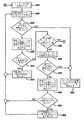
図24Aから図24Eは、カッター104が上述した4つの別個の位置を経由して移動する際に、カッター104の操作を制御するための、この発明による制御方法を示すフロー図を与えている。制御方法の複数のステップはフロー図に概略的に示されている。フロー図における各ボックスは1ステップまたは1ステップ以上の複数ステップを示す場合がある。議論の目的のために、各ボックスは単に1つのステップとする。複数ステップは、概ね、複数のボックスを連結する矢印の方向へ進む。以下に記述される制御方法では、図1から図17に示された第1の実施の形態のように、単独モータを有するか、あるいはカッターの平行移動および回転移動を別々に駆動するための2つまたはそれ以上のモータを有する生検装置を使用してもよい。 FIGS. 24A-24E provide a flow diagram illustrating a control method according to the present invention for controlling the operation of the
図24Aを参照すると、ステップ410は、制御方法の開始を示している。生検装置20が採取モードあるいは手動操作モードのいずれかを選択することによるなどの用途に作動されるときに、制御信号は電力コード(制御コード)48を経由してスイッチボード(配電盤)198に送信される。配電盤198は、パルス幅変調(PWM)方式がモータ188に供給されるべき信号を駆動して平行移動駆動シャフト160の回転運動を開始させるように、順に命令する。平行移動駆動シャフト160の回転運動は、遠位端162とスロット158との相互接続を通じて平行移動シャフト142に伝達される。平行移動シャフト142は回転し、カムナット136は、可変ピッチの主ネジ溝144におけるカムフロアピン152の動作により、位置1から位置2へのカッター104の平行移動を開始する。平行移動シャフト142に沿うカムナット136の平行移動をステップ412において続行する。 Referring to FIG. 24A,
ステップ414では、制御ユニット24における書換え可能メモリ内に格納された予定時間値は読み取られ、一時メモリ内に格納された蓄積時間数と比較される。上記書換え可能メモリは、例えばマイクロチップコーポレーション社によって製造されたPIC18F452等のマイクロコントローラに内蔵されている、例えば「フラッシュ」メモリとしてもよい。予定時間値は、カッターの平行移動用の通路内の指定位置に対応している。一時メモリ内の蓄積時間数は、略等しい時間間隔でマイクロコントローラによって更新される。1つの実施の形態では、時間間隔は、約100ミリ秒以下、より詳細には約50ミリ秒以下とすることができ、1つの実施の形態では約25ミリ秒とすることができる。上記蓄積時間数は、カッター104が相対的な位置1から位置4へ平行移動し、以下により詳細に記述されるモータ電圧対照から算出される時間がプラス(あるいはマイナス)される実時間から導き出される。一時メモリ内の蓄積時間数は予定時間値に適合しているときには、カッター104は位置2にあるものと考えられる。仮に一時メモリ内の蓄積時間数が位置2に関する予定時間値に適合していない場合には、カッター104は位置2にあるものと考えられず、操作はステップ416へ進む。 In
ステップ416では、平行移動モータの現在の電流値が平行移動モータ188から読み取られる。ステップ418では、平行移動モータの現在の電流測定値は、フラッシュメモリ内に格納された予定電流限界値と比較される。仮に電流測定値が予定電流限界値より大きい場合には、エラー状態であると判断されてプログラムを終了する。平行移動モータ188の運転は停止され、エラーメッセージはステップ420においてユーザーインターフェース上で報告される。仮にステップ418が平行移動モータの現在の電流値が予定電流限界値以下である場合には、制御方法はステップ422へ進む。 In
ステップ422では、平行移動モータの現在の電流値が、以下「電流参照用テーブル(Look-Up Table)」と呼ばれる書換え可能メモリ内に格納された予定電流限界値と比較される。電流参照用テーブルは、駆動モータ186および188のそれぞれの代表的な電流プロファイルを含む。電流プロファイルは、モータ運転および駆動電流に関係した実験的で経験的なデータから導き出される。電流プロファイルは、マイクロコントローラの時間間隔に対応し、この明細書に記述された例示の実施の形態では25ミリ秒である時間間隔に分化される。この比較で使用されるべき予定電流値の電流参照用テーブルにおける位置は、上記比較の時刻における蓄積時間数に依存している。図25は、カッター104が位置1から位置4へ進行した後に再び位置1へ戻る完全なサイクルを横切る際のモータ電流プロファイル260の例を示している。図25では、電流プロファイル260は、時間(水平軸)に対するモータ電流(垂直軸)として示されている。電流プロファイル260によって示されているように、モータ188への電流は、時間の増分間と4つのカッター位置間で変化する。電流参照用テーブルは、分化された時間間隔ごとに電流プロファイル260を含む。 In
上記電流の測定に加えて、ステップ422では、平行移動モータ188の電圧は、パルス幅変調(PWM)方式のモータ駆動信号のサイクルから外れている間に、読み取られる。この電圧は、モータ188の電気機械的な戻り力、並びにカッター104の直線移動速度に比例する。電圧測定値から、移動通路に沿うカムナット136の実際の位置、したがってカッター104の位置は確認可能である。モータ188から読み取られた電圧は、モータの規格値あるいは予定された操作プロファイルと比較されて、上記測定電圧から実際の移動速度を判断してもよい。仮に蓄積時間数で読み取られたモータ電圧が上記蓄積時間数に関する予想電圧を超える場合には、カッター104は、蓄積時間数に対する予想電圧よりも電流プロファイルにおける進行した位置にあるものと考えられる。したがって、電流参照用テーブルにおけるポインタの位置は、蓄積時間数を増やすことによる移動距離差の原因となるように調節され、これによりカッターの全進行時間を遅延させることができる。同様に、仮に読み取られたモータ電圧が上記蓄積時間数に関する予想電圧よりも小さい場合には、カッター104は、蓄積時間数によって予想されているように電流プロファイルに沿って遠くへ移動しなかったものと考えられる。したがって、電流参照用テーブルにおけるポインタの位置は、蓄積時間数を減らすことによる移動距離差の原因となるように調節され、これにより再度、読み取られるか、あるいは電流参照用テーブルにおいて後方へ移動させ、カッターの全進行時間を増やすことができる。 In addition to the current measurement, in
ステップ424では、平行移動モータの現在の電流値と電流参照用テーブルからの電流値との差が、図25における破線262によって示された範囲等、予定範囲から外れているか否かを確認するために、比較がなされる。仮に電流値間の差が上記予想範囲外である場合には、平行移動モータ188に対する電流が、動作サイクルのパルス幅が変調されたモータ制御信号を増加または減少させる(あるいは仮にPWMではなくアナログ式のモータ駆動が用いられる場合に電圧レベルを変化させる)ことなどにより、ステップ426で調節される。仮に平行移動モータの現在の電流値と電流参照用テーブルの予定電流値との差が許容範囲内であるようにステップ424で確認された場合には、その後、プロセスはステップ412へ戻り、カッター104は位置1から位置2へ平行移動し続ける。 In
ステップ414では、仮にカッター104が位置2にあるものと考えられる場合には、その後に、制御方法は図24Bに示されたステップ428へ進み、カッター104は位置2から位置3へ平行移動し続ける。ステップ430では、カッター104が位置2と位置3との間の予定した中間位置に到達しているか否かを確認するために、点検がなされる。カッター104は、一時メモリ内の蓄積時間数が上記中間位置に対応する予定時間数に適合する場合に、上記中間位置に到達したものと考えられる。予定した中間位置は、実際のカッターの平行移動速度および予定したカッターの回転速度に基づいている。上記中間位置は、組織切除を開始した後で、カッター104が位置4に到達する前に、カッター104にとって十分な時間が零の回転速度から予定した回転速度へ加速することを可能にするように、選択される。ステップ430では、カッター104が上記中間位置に到達しなかった場合には、その後に、ステップ432で、平行移動モータの現在の電流値はモータ188から読み取られる。 In
ステップ434では、平行移動モータの現在の電流値は、フラッシュメモリ内に格納された予定電流限界値と再び比較される。仮に平行移動モータの現在の電流値が上記予定電流限界値よりも大きい場合には、エラー状態であると判断されてプログラムを終了する。平行移動モータ188の運転は停止され、エラーメッセージはステップ436においてユーザーインターフェース上で報告される。仮にステップ434が平行移動モータの現在の電流値が予定電流限界値以下である場合には、生検装置20の操作をステップ438で続行する。ステップ438では、平行移動モータの現在の電流測定値は電流参照用テーブル内の予定値と再び比較される。一旦もう一度、電流参照用テーブル内の比較値の位置は、上記比較の時刻で更新された蓄積時間数に依存する。また、ステップ438では、現在のモータ電圧は、読み取られ、更新された蓄積時間数に基づく予想電圧と比較される。仮に実際の電圧測定値が予想電圧と異なる場合には、その後に、蓄積時間数は増加あるいは減少されて、電流参照用テーブルの位置を上記カッター104の実際位置と同調させる。ステップ440では、仮に現在の電流値と予定電流値との差が予定範囲外にある場合には、平行移動モータ188への電流はステップ442で調節される。仮にステップ440での比較差が予定範囲内にある場合には、その後に、カッター104はステップ428において現速度で位置2から位置3へ平行移動し続ける。 In
ステップ430では、仮にカッター104が位置2と位置3との間の中間位置に到達したことが確認される場合には、その後に、カッター104は位置3に向けて平行移動を続行し、カッター104の回転は図24Cに示されたステップ444で開始される。ステップ446では、回転モータの現在の電流値は回転駆動モータ186で読み取られる。ステップ448では、回転モータの現在の電流値がフラッシュメモリ内に格納された予定電流限界値より大きいか否かを確認するために、比較がなされる。仮に現在の電流測定値が上記予定電流限界値よりも大きい場合には、その後に、回転駆動モータ186および平行移動駆動モータ188はステップ460で停止され、エラー状態はユーザーインターフェース上で報告される。仮に回転モータの現在の電流測定値が上記予定電流限界値以下である場合には、その後に、操作は次のステップで続行する。ステップ450では、回転モータの現在の電流測定値は、電流参照用テーブル内にロードされた予定電流値と比較される。上述したように、電流参照用テーブル内の比較値の位置は、上記比較の時刻における蓄積時間数に依存している。ステップ452では、仮に比較差が予定範囲外であると確認される場合には、回転駆動モータ186への電流はステップ454で調節される。ステップ452では、仮に現在の電流値と予定電流値との差が予定範囲内にある場合には、カッター104の回転運動を続行する。 In
ステップ456では、マイクロコントローラ内のメモリ内に格納された予定時間値は一時メモリ内に格納された蓄積時間数と比較される。蓄積時間数は、カッターが相対位置を経由して移動し、ステップ422、438および464でのモータ電圧比較から算出された時間をプラス(あるいはマイナス)される実時間から導き出される。蓄積時間数が格納された時間数に適合するときには、カッター104は位置3にあるものと判断される。仮にカッター104が位置3にない場合には、プロセスは、平行移動モータの現在の電流値がモータ188から読み取られるステップ458で続行する。ステップ462では、平行移動モータの現在の電流測定値は、予定電流限界値と比較される。仮に平行移動モータの現在の電流測定値が予定電流限界値より大きい場合には、平行移動および回転移動モータは停止され、エラーはステップ460で報告される。 In
仮に上記測定値が上記限界値以下である場合には、プロセスは、現在の電流測定値が電流参照用テーブル内にロードされた予定値と比較されるステップ464で続行する。電流参照用テーブル内の比較値の位置は、上記比較の時刻で更新された蓄積時間数に依存する。また、ステップ464では、実際のモータ電圧は、予想電圧と比較される。上記蓄積時間数は、カッター104の実際の移動速度での変化に対応するモータ電圧の増減の原因となるように、上述したように増減される。ステップ466では、仮に現在の電流測定値と電流参照用テーブルからの予定電流値との差が許容範囲内にあるものと確認される場合には、カッター104の平行移動を続行し、プロセスはステップ446へ進む。仮に比較との差が予定された許容範囲外である場合には、その後に、平行移動モータ468への電流は調節される。この調節後に、プロセスはステップ446で続行する。 If the measured value is less than or equal to the limit value, the process continues at
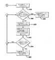
カッター104が位置3に到達したことをステップ456で確認されたときには、その後に、プロセスは図24Dで示されたステップ470へ進む。ステップ470では、モータ188への平行移動用電流は、メモリ内に格納された予定値に変更される。変更された電流値は、異なる速度、典型的には0.5インチ/秒であるが、位置4に向けたカッター104の平行移動を継続させる。ステップ472では、マイクロプロセッサ内の書換え可能メモリ内に格納された予定値は、一時メモリ内に格納された蓄積時間数と比較される。時間数は、カッター104が相対的な位置を経由して移動し、モータ電圧対照から算出される時間がプラス(あるいはマイナス)される実時間から導き出される。現在の時間数が格納された時間数に適合するときには、カッターが位置4にあるものと考えられる。 If it is confirmed in
ステップ474では、平行移動モータの現在の電流値は読み取られる。ステップ476では、平行移動モータの電流測定値は、予定電流限界値と比較される。仮に平行移動モータの電流測定値が予定電流限界値より大きい場合には、プロセスは、回転移動モータ186および平行移動モータ188が停止されかつエラーメッセージが表示されるステップ482へ移行する。ステップ476では、仮に平行移動モータの現在の電流測定値が上記予定電流限界値以下である場合には、プロセスはステップ478で続行する。ステップ478では、モータ電圧は読み取られ、かつモータの予定電圧レベルと比較される。仮に電圧測定値が予想値よりも高い場合には、その後に、蓄積時間数は、カッターの移動速度の上昇の原因となるように増加される。仮に電圧測定値が予想値よりも低い場合には、その後に、蓄積時間数は、カッターの移動速度の低下の原因となるように低減される。また、ステップ478では、平行移動モータの現在の電流測定値は、電流参照用テーブルにロードされた予定値と比較される。ステップ480では、仮に現在の電流値と予定電流値との差が予定範囲外にあるものと確認される場合には、ステップ484で平行移動モータ188への電流が調節される。ステップ480では、仮に現在の電流値と予定電流値との差が予定範囲内にある場合には、その後に、カッター104は平行移動を続行し、プロセスはステップ486へ移行する。ステップ486では、回転モータの現在の電流値は、再び読み取られ、ステップ488では、最新の電流測定値は、予定電流限界値と比較される。仮に電流測定値が予定電流限界値よりも大きい場合には、平行移動モータ188および回転移動モータ186は停止され、エラーはステップ482で報告される。仮に回転モータの現在の電流測定値が予定電流限界値以下である場合には、その後に、操作は次のステップで続行する。ステップ490では、回転モータの現在の電流値が電流参照用テーブルにロードされた予定電流値と比較され、上記2つの値間の差は算出される。仮に電流レベルにおける差が予定範囲外であるとステップ492で確認される場合には、その後に、ステップ494で、回転モータの電流は調節される。ステップ492では、上記2つの電流値間の差が予定範囲内にあるものと確認される場合には、その後に、カッターの回転は続行し、プロセスはステップ472へ移行する。 In
ステップ472では、仮にカッター104が位置4へ到達した場合には、その後に、制御方法は、平行移動モータ188が停止されるステップ496で続行する。次に、ステップ498では、マイクロコントローラ内に格納された予定値は、一時メモリ内に格納された蓄積時間数と比較される。この蓄積時間数は、回転モータがモータ電圧比較から算出されたプラス(あるいはマイナス)調節時間で始動された実際の時間から導き出される。ステップ498では、仮に比較された時間数が格納された時間数に適合しない場合には、その後に、回転モータの実際の電流はステップ500で読み取られる。ステップ502では、回転モータの実際の電流は、電流参照用テーブル内の比較値の位置が比較時における時間数の間隔に依存する電流参照用テーブルにロードされた予定ちと比較される。仮にステップ504で回転モータの実際の電流と回転モータの予定電流値との差が予定範囲外である場合には、その後に、回転モータ186への電流はステップ506で調節される。仮に比較との差が予定範囲内にある場合には、その後に、制御方法はステップ498へ移行する。ステップ498では、予定時間数は回転モータ186に関する蓄積時間数と比較される。仮に蓄積時間数が予定時間数を超える場合には、その後に、回転モータはステップ508で停止される。 In step 472, if the
電気モータが上述した実施の形態に開示されているが、空気圧駆動式モータ等の他のタイプのモータが使用可能であると理解されるはずである。さらに、内部カッターを有する外カニューレが開示されているが、カッターがカニューレ外の周囲に同軸的に配された実施の形態等の他の変形も使用されてもよい。 Although an electric motor is disclosed in the above-described embodiments, it should be understood that other types of motors, such as pneumatically driven motors, can be used. Furthermore, although an outer cannula having an inner cutter is disclosed, other variations such as embodiments in which the cutter is coaxially disposed around the outside of the cannula may be used.
この発明の好適な実施の形態が図示されかつこの明細書に記述されているが、そのような実施の形態は例示の目的のみによって与えられているものと、この技術分野における当業者にとって明白なはずである。多くの変形、変更および置換は、添付された請求項の精神および範囲から逸脱することなく、この技術分野における当業者によって見出されるはずである。さらに、開示された各構成要素は、この構成要素の機能を実行するための他の手段として記述されてもよい。 While preferred embodiments of the invention have been illustrated and described herein, such embodiments are given by way of example only and will be apparent to those skilled in the art. It should be. Many variations, modifications and substitutions should be found by those skilled in the art without departing from the spirit and scope of the appended claims. Further, each disclosed component may be described as another means for performing the function of the component.
Claims (6)
Translated fromJapanese側方の組織受容ポートを有する外カニューレと、
前記外カニューレ内で平行移動および回転移動のいずれかまたは両方を行うように配置された内管状のカッターと、
ピッチが変化しているネジ部を有する回転部材と、
前記回転部材の前記ネジ部に係合し、前記回転部材が回転すると、前記回転部材に沿って平行移動するように支持されたカムナットと、を含み、
前記カッターは、前記カムナット上で回転可能に支持されることにより、前記回転部材の回転に従って前記カムナットが前進すると、前記カムナットに押圧されることによって前進し、
前記回転部材は、相対的に粗いピッチ部分と、相対的に細かいピッチ部分とを含み、前記相対的に細かいピッチ部分は、前記カッターが前記組織受容ポートに対して前進する際に、前記カッターの平行移動速度を低下させるように構成され、
前記回転部材は遠位端に零ピッチ領域を備えることにより、前記カッターが最も遠位側の位置にあるときに、前記カッターが平行移動することなく回転移動するように構成される、生検装置。A biopsy device,
An outer cannula having a lateral tissue receiving port;
An inner tubular cutter arranged to perform either or both of translation and rotation within the outer cannula;
A rotating member having a threaded portion with varying pitch;
A cam nut that engages with the threaded portion of the rotating member and is supported to translate along the rotating member when the rotating member rotates,
The cutter is supported rotatably on the cam nut so that when the cam nut advances according to the rotation of the rotating member, the cutter advances by being pressed by the cam nut,
The rotating member includes a relatively coarse pitch portion and a relatively fine pitch portion, the relatively fine pitch portion of the cutter as the cutter advances relative to the tissue receiving port. Configured to reduce translation speed,
The rotating member comprises azero pitch region at the distal end so that when the cutter is in the most distal position, the cutter is configured to rotate without translation. .
Applications Claiming Priority (5)
| Application Number | Priority Date | Filing Date | Title |
|---|---|---|---|
| US44997003P | 2003-02-25 | 2003-02-25 | |
| US60/449,970 | 2003-02-25 | ||
| PCT/US2004/005381WO2004075728A2 (en) | 2003-02-25 | 2004-02-24 | Biopsy device with variable speed cutter advance |
| US10/785,755 | 2004-02-24 | ||
| US10/785,755US7025732B2 (en) | 2003-02-25 | 2004-02-24 | Biopsy device with variable speed cutter advance |
Publications (2)
| Publication Number | Publication Date |
|---|---|
| JP2006518654A JP2006518654A (en) | 2006-08-17 |
| JP4754474B2true JP4754474B2 (en) | 2011-08-24 |
Family
ID=32930534
Family Applications (1)
| Application Number | Title | Priority Date | Filing Date |
|---|---|---|---|
| JP2006503828AExpired - LifetimeJP4754474B2 (en) | 2003-02-25 | 2004-02-24 | Biopsy device with variable speed cutter |
Country Status (7)
| Country | Link |
|---|---|
| US (5) | US7025732B2 (en) |
| EP (1) | EP1603462B1 (en) |
| JP (1) | JP4754474B2 (en) |
| AU (2) | AU2004216206B2 (en) |
| BR (1) | BRPI0407847A (en) |
| CA (1) | CA2517242C (en) |
| WO (1) | WO2004075728A2 (en) |
Cited By (2)
| Publication number | Priority date | Publication date | Assignee | Title |
|---|---|---|---|---|
| JP2017080501A (en)* | 2014-02-28 | 2017-05-18 | スリーディーバイオプシー,インコーポレーテッド | Biopsy needle actuator device |
| WO2018236113A1 (en)* | 2017-06-19 | 2018-12-27 | 운스메디칼 주식회사 | Needle assembly for biopsy to reduce starting load when changing direction of motor |
Families Citing this family (723)
| Publication number | Priority date | Publication date | Assignee | Title |
|---|---|---|---|---|
| NL1006944C2 (en) | 1997-09-04 | 1999-03-11 | Mark Hans Emanuel | Surgical endoscopic cutting device. |
| US20030060765A1 (en)* | 2000-02-16 | 2003-03-27 | Arthur Campbell | Infusion device menu structure and method of using the same |
| US11229472B2 (en) | 2001-06-12 | 2022-01-25 | Cilag Gmbh International | Modular battery powered handheld surgical instrument with multiple magnetic position sensors |
| US7226459B2 (en) | 2001-10-26 | 2007-06-05 | Smith & Nephew, Inc. | Reciprocating rotary arthroscopic surgical instrument |
| EP1524940B1 (en) | 2002-03-19 | 2011-08-24 | Bard Dublin ITC Limited | Biopsy device and biopsy needle module that can be inserted into the biopsy device |
| US8109885B2 (en) | 2002-03-19 | 2012-02-07 | C. R. Bard, Inc. | Biopsy device for removing tissue specimens using a vacuum |
| US20070049945A1 (en) | 2002-05-31 | 2007-03-01 | Miller Larry J | Apparatus and methods to install, support and/or monitor performance of intraosseous devices |
| US10973545B2 (en) | 2002-05-31 | 2021-04-13 | Teleflex Life Sciences Limited | Powered drivers, intraosseous devices and methods to access bone marrow |
| EP2039298B1 (en) | 2002-05-31 | 2017-10-25 | Vidacare LLC | Apparatus to access bone marrow |
| US9314228B2 (en)* | 2002-05-31 | 2016-04-19 | Vidacare LLC | Apparatus and method for accessing the bone marrow |
| US11298202B2 (en) | 2002-05-31 | 2022-04-12 | Teleflex Life Sciences Limited | Biopsy devices and related methods |
| US7811260B2 (en) | 2002-05-31 | 2010-10-12 | Vidacare Corporation | Apparatus and method to inject fluids into bone marrow and other target sites |
| US8142365B2 (en) | 2002-05-31 | 2012-03-27 | Vidacare Corporation | Apparatus and method for accessing the bone marrow of the sternum |
| US8641715B2 (en) | 2002-05-31 | 2014-02-04 | Vidacare Corporation | Manual intraosseous device |
| US9072543B2 (en) | 2002-05-31 | 2015-07-07 | Vidacare LLC | Vascular access kits and methods |
| US8668698B2 (en) | 2002-05-31 | 2014-03-11 | Vidacare Corporation | Assembly for coupling powered driver with intraosseous device |
| US9451968B2 (en)* | 2002-05-31 | 2016-09-27 | Vidacare LLC | Powered drivers, intraosseous devices and methods to access bone marrow |
| US7951089B2 (en) | 2002-05-31 | 2011-05-31 | Vidacare Corporation | Apparatus and methods to harvest bone and bone marrow |
| US11337728B2 (en) | 2002-05-31 | 2022-05-24 | Teleflex Life Sciences Limited | Powered drivers, intraosseous devices and methods to access bone marrow |
| US10973532B2 (en) | 2002-05-31 | 2021-04-13 | Teleflex Life Sciences Limited | Powered drivers, intraosseous devices and methods to access bone marrow |
| US7850620B2 (en)* | 2002-05-31 | 2010-12-14 | Vidacare Corporation | Biopsy devices and related methods |
| US8690791B2 (en) | 2002-05-31 | 2014-04-08 | Vidacare Corporation | Apparatus and method to access the bone marrow |
| US20040068230A1 (en)* | 2002-07-24 | 2004-04-08 | Medtronic Minimed, Inc. | System for providing blood glucose measurements to an infusion device |
| ATE383111T1 (en)* | 2002-08-01 | 2008-01-15 | James E Selis | BIOPSY DEVICES |
| JP4754474B2 (en)* | 2003-02-25 | 2011-08-24 | エシコン・エンド−サージェリィ・インコーポレイテッド | Biopsy device with variable speed cutter |
| DE10314240B4 (en) | 2003-03-29 | 2025-05-28 | Bard Dublin Itc Ltd. | Pressure generation unit |
| DE20305093U1 (en) | 2003-03-29 | 2003-09-11 | Heske, Norbert F., 82288 Kottgeisering | Coaxial cannula with sealing element |
| US20070084897A1 (en) | 2003-05-20 | 2007-04-19 | Shelton Frederick E Iv | Articulating surgical stapling instrument incorporating a two-piece e-beam firing mechanism |
| US9060770B2 (en) | 2003-05-20 | 2015-06-23 | Ethicon Endo-Surgery, Inc. | Robotically-driven surgical instrument with E-beam driver |
| US9504477B2 (en) | 2003-05-30 | 2016-11-29 | Vidacare LLC | Powered driver |
| US8357103B2 (en)* | 2003-10-14 | 2013-01-22 | Suros Surgical Systems, Inc. | Vacuum assisted biopsy needle set |
| CN101536926B (en) | 2004-01-26 | 2012-07-18 | 维达保健公司 | Manual interosseous device |
| US7815642B2 (en) | 2004-01-26 | 2010-10-19 | Vidacare Corporation | Impact-driven intraosseous needle |
| US7708751B2 (en) | 2004-05-21 | 2010-05-04 | Ethicon Endo-Surgery, Inc. | MRI biopsy device |
| US9638770B2 (en) | 2004-05-21 | 2017-05-02 | Devicor Medical Products, Inc. | MRI biopsy apparatus incorporating an imageable penetrating portion |
| US8932233B2 (en) | 2004-05-21 | 2015-01-13 | Devicor Medical Products, Inc. | MRI biopsy device |
| US8075568B2 (en) | 2004-06-11 | 2011-12-13 | Selis James E | Biopsy devices and methods |
| JP4814229B2 (en) | 2004-07-09 | 2011-11-16 | バード ペリフェラル ヴァスキュラー インコーポレイテッド | Transport device for biopsy device |
| US8215531B2 (en) | 2004-07-28 | 2012-07-10 | Ethicon Endo-Surgery, Inc. | Surgical stapling instrument having a medical substance dispenser |
| US11998198B2 (en) | 2004-07-28 | 2024-06-04 | Cilag Gmbh International | Surgical stapling instrument incorporating a two-piece E-beam firing mechanism |
| US11890012B2 (en) | 2004-07-28 | 2024-02-06 | Cilag Gmbh International | Staple cartridge comprising cartridge body and attached support |
| US9072535B2 (en) | 2011-05-27 | 2015-07-07 | Ethicon Endo-Surgery, Inc. | Surgical stapling instruments with rotatable staple deployment arrangements |
| ITBO20040532A1 (en)* | 2004-08-26 | 2004-11-26 | Aticarta S P A | RIGID WRAPPING FOR SMOKING ITEMS WITH HINGED COVER CONNECTED BY GLUING |
| US8062214B2 (en) | 2004-08-27 | 2011-11-22 | Smith & Nephew, Inc. | Tissue resecting system |
| US7740596B2 (en)* | 2004-09-29 | 2010-06-22 | Ethicon Endo-Surgery, Inc. | Biopsy device with sample storage |
| US20060074345A1 (en) | 2004-09-29 | 2006-04-06 | Hibner John A | Biopsy apparatus and method |
| US7740594B2 (en) | 2004-09-29 | 2010-06-22 | Ethicon Endo-Surgery, Inc. | Cutter for biopsy device |
| US8998848B2 (en) | 2004-11-12 | 2015-04-07 | Vidacare LLC | Intraosseous device and methods for accessing bone marrow in the sternum and other target areas |
| US7517321B2 (en) | 2005-01-31 | 2009-04-14 | C. R. Bard, Inc. | Quick cycle biopsy system |
| US20060184063A1 (en)* | 2005-02-15 | 2006-08-17 | Miller Michael E | Single motor handheld biopsy device |
| JP2008531093A (en)* | 2005-02-23 | 2008-08-14 | ノボ・ノルデイスク・エー/エス | Method and apparatus for reversing a piston rod in an injection device |
| GB2423591B (en)* | 2005-02-25 | 2010-01-27 | Tippetts Fountains Ltd | Fluidic oscillator and display fountain |
| US7662109B2 (en)* | 2006-02-01 | 2010-02-16 | Ethicon Endo-Surgery, Inc. | Biopsy device with replaceable probe incorporating static vacuum source dual valve sample stacking retrieval and saline flush |
| US7867173B2 (en)* | 2005-08-05 | 2011-01-11 | Devicor Medical Products, Inc. | Biopsy device with replaceable probe and incorporating vibration insertion assist and static vacuum source sample stacking retrieval |
| US7854707B2 (en) | 2005-08-05 | 2010-12-21 | Devicor Medical Products, Inc. | Tissue sample revolver drum biopsy device |
| USRE46135E1 (en) | 2005-08-05 | 2016-09-06 | Devicor Medical Products, Inc. | Vacuum syringe assisted biopsy device |
| JP4991723B2 (en) | 2005-08-10 | 2012-08-01 | シー・アール・バード・インコーポレーテッド | Single insertion multiple sampling biopsy device with integrated marker |
| ES2539578T3 (en) | 2005-08-10 | 2015-07-02 | C.R. Bard, Inc. | Multi-sample biopsy device and single insert with various transport systems |
| EP1921998B8 (en) | 2005-08-10 | 2021-07-07 | C.R.Bard, Inc. | Single-insertion, multiple sampling biopsy device with linear drive |
| US7669746B2 (en) | 2005-08-31 | 2010-03-02 | Ethicon Endo-Surgery, Inc. | Staple cartridges for forming staples having differing formed staple heights |
| US10159482B2 (en) | 2005-08-31 | 2018-12-25 | Ethicon Llc | Fastener cartridge assembly comprising a fixed anvil and different staple heights |
| US7934630B2 (en) | 2005-08-31 | 2011-05-03 | Ethicon Endo-Surgery, Inc. | Staple cartridges for forming staples having differing formed staple heights |
| US11246590B2 (en) | 2005-08-31 | 2022-02-15 | Cilag Gmbh International | Staple cartridge including staple drivers having different unfired heights |
| US9237891B2 (en) | 2005-08-31 | 2016-01-19 | Ethicon Endo-Surgery, Inc. | Robotically-controlled surgical stapling devices that produce formed staples having different lengths |
| US11484312B2 (en) | 2005-08-31 | 2022-11-01 | Cilag Gmbh International | Staple cartridge comprising a staple driver arrangement |
| US20070106317A1 (en) | 2005-11-09 | 2007-05-10 | Shelton Frederick E Iv | Hydraulically and electrically actuated articulation joints for surgical instruments |
| US20070149881A1 (en)* | 2005-12-22 | 2007-06-28 | Rabin Barry H | Ultrasonically Powered Medical Devices and Systems, and Methods and Uses Thereof |
| US20110024477A1 (en) | 2009-02-06 | 2011-02-03 | Hall Steven G | Driven Surgical Stapler Improvements |
| US20110295295A1 (en) | 2006-01-31 | 2011-12-01 | Ethicon Endo-Surgery, Inc. | Robotically-controlled surgical instrument having recording capabilities |
| US8820603B2 (en) | 2006-01-31 | 2014-09-02 | Ethicon Endo-Surgery, Inc. | Accessing data stored in a memory of a surgical instrument |
| US8708213B2 (en) | 2006-01-31 | 2014-04-29 | Ethicon Endo-Surgery, Inc. | Surgical instrument having a feedback system |
| US11278279B2 (en) | 2006-01-31 | 2022-03-22 | Cilag Gmbh International | Surgical instrument assembly |
| US7845537B2 (en) | 2006-01-31 | 2010-12-07 | Ethicon Endo-Surgery, Inc. | Surgical instrument having recording capabilities |
| US11793518B2 (en) | 2006-01-31 | 2023-10-24 | Cilag Gmbh International | Powered surgical instruments with firing system lockout arrangements |
| US8186555B2 (en) | 2006-01-31 | 2012-05-29 | Ethicon Endo-Surgery, Inc. | Motor-driven surgical cutting and fastening instrument with mechanical closure system |
| US7753904B2 (en) | 2006-01-31 | 2010-07-13 | Ethicon Endo-Surgery, Inc. | Endoscopic surgical instrument with a handle that can articulate with respect to the shaft |
| US11224427B2 (en) | 2006-01-31 | 2022-01-18 | Cilag Gmbh International | Surgical stapling system including a console and retraction assembly |
| US20120292367A1 (en) | 2006-01-31 | 2012-11-22 | Ethicon Endo-Surgery, Inc. | Robotically-controlled end effector |
| US7806834B2 (en)* | 2006-03-07 | 2010-10-05 | Devicor Medical Products, Inc. | Device for minimally invasive internal tissue removal |
| US8992422B2 (en) | 2006-03-23 | 2015-03-31 | Ethicon Endo-Surgery, Inc. | Robotically-controlled endoscopic accessory channel |
| US20070232954A1 (en)* | 2006-04-04 | 2007-10-04 | Harris Jeffrey P | Automated skin biopsy device |
| US7585547B2 (en)* | 2006-04-13 | 2009-09-08 | Solopower, Inc. | Method and apparatus to form thin layers of materials on a base |
| US8322455B2 (en) | 2006-06-27 | 2012-12-04 | Ethicon Endo-Surgery, Inc. | Manually driven surgical cutting and fastening instrument |
| EP3417792B1 (en) | 2006-08-21 | 2022-03-02 | C. R. Bard, Inc. | Self-contained handheld biopsy needle |
| EP2068743B1 (en) | 2006-09-12 | 2017-03-15 | Vidacare LLC | Medical procedures trays, kits and related methods |
| EP3189787B1 (en) | 2006-09-12 | 2019-01-09 | Teleflex Medical Devices S.à.r.l. | Medical procedures trays and related methods |
| US8944069B2 (en) | 2006-09-12 | 2015-02-03 | Vidacare Corporation | Assemblies for coupling intraosseous (IO) devices to powered drivers |
| EP2073728B1 (en)* | 2006-09-12 | 2018-11-07 | Teleflex Medical Devices S.à.r.l. | Biopsy device |
| US10568652B2 (en) | 2006-09-29 | 2020-02-25 | Ethicon Llc | Surgical staples having attached drivers of different heights and stapling instruments for deploying the same |
| US7506791B2 (en) | 2006-09-29 | 2009-03-24 | Ethicon Endo-Surgery, Inc. | Surgical stapling instrument with mechanical mechanism for limiting maximum tissue compression |
| US11980366B2 (en) | 2006-10-03 | 2024-05-14 | Cilag Gmbh International | Surgical instrument |
| SI2086418T1 (en) | 2006-10-06 | 2011-05-31 | Bard Peripheral Vascular Inc | Tissue handling system with reduced operator exposure |
| US8262586B2 (en) | 2006-10-24 | 2012-09-11 | C. R. Bard, Inc. | Large sample low aspect ratio biopsy needle |
| US8974410B2 (en) | 2006-10-30 | 2015-03-10 | Vidacare LLC | Apparatus and methods to communicate fluids and/or support intraosseous devices |
| US7981049B2 (en)* | 2006-12-13 | 2011-07-19 | Devicor Medical Products, Inc. | Engagement interface for biopsy system vacuum module |
| US8702623B2 (en) | 2008-12-18 | 2014-04-22 | Devicor Medical Products, Inc. | Biopsy device with discrete tissue chambers |
| US8480595B2 (en) | 2006-12-13 | 2013-07-09 | Devicor Medical Products, Inc. | Biopsy device with motorized needle cocking |
| US9345457B2 (en) | 2006-12-13 | 2016-05-24 | Devicor Medical Products, Inc. | Presentation of biopsy sample by biopsy device |
| US8251916B2 (en)* | 2006-12-13 | 2012-08-28 | Devicor Medical Products, Inc. | Revolving tissue sample holder for biopsy device |
| US20140039343A1 (en) | 2006-12-13 | 2014-02-06 | Devicor Medical Products, Inc. | Biopsy system |
| US20130324882A1 (en)* | 2012-05-30 | 2013-12-05 | Devicor Medical Products, Inc. | Control for biopsy device |
| EP2120724B1 (en)* | 2006-12-13 | 2017-02-08 | Devicor Medical Products, Inc. | Biopsy device |
| US7938786B2 (en)* | 2006-12-13 | 2011-05-10 | Devicor Medical Products, Inc. | Vacuum timing algorithm for biopsy device |
| US8632535B2 (en) | 2007-01-10 | 2014-01-21 | Ethicon Endo-Surgery, Inc. | Interlock and surgical instrument including same |
| US8652120B2 (en) | 2007-01-10 | 2014-02-18 | Ethicon Endo-Surgery, Inc. | Surgical instrument with wireless communication between control unit and sensor transponders |
| US11291441B2 (en) | 2007-01-10 | 2022-04-05 | Cilag Gmbh International | Surgical instrument with wireless communication between control unit and remote sensor |
| US8684253B2 (en)* | 2007-01-10 | 2014-04-01 | Ethicon Endo-Surgery, Inc. | Surgical instrument with wireless communication between a control unit of a robotic system and remote sensor |
| US20080169333A1 (en) | 2007-01-11 | 2008-07-17 | Shelton Frederick E | Surgical stapler end effector with tapered distal end |
| US11039836B2 (en) | 2007-01-11 | 2021-06-22 | Cilag Gmbh International | Staple cartridge for use with a surgical stapling instrument |
| US7673782B2 (en) | 2007-03-15 | 2010-03-09 | Ethicon Endo-Surgery, Inc. | Surgical stapling instrument having a releasable buttress material |
| US8893946B2 (en) | 2007-03-28 | 2014-11-25 | Ethicon Endo-Surgery, Inc. | Laparoscopic tissue thickness and clamp load measuring devices |
| US20080281224A1 (en)* | 2007-05-11 | 2008-11-13 | Johnson Michael E | Biopsy device needle tip |
| CN101711129B (en)* | 2007-05-17 | 2012-07-04 | 普罗德克斯有限公司 | Handheld medical device |
| US8931682B2 (en) | 2007-06-04 | 2015-01-13 | Ethicon Endo-Surgery, Inc. | Robotically-controlled shaft based rotary drive systems for surgical instruments |
| US11564682B2 (en) | 2007-06-04 | 2023-01-31 | Cilag Gmbh International | Surgical stapler device |
| US7753245B2 (en) | 2007-06-22 | 2010-07-13 | Ethicon Endo-Surgery, Inc. | Surgical stapling instruments |
| US11849941B2 (en) | 2007-06-29 | 2023-12-26 | Cilag Gmbh International | Staple cartridge having staple cavities extending at a transverse angle relative to a longitudinal cartridge axis |
| US20090204022A1 (en)* | 2007-09-13 | 2009-08-13 | Tissue Extraction Devices, Llc | Pneumatic Circuit and Biopsy Device |
| US8808200B2 (en) | 2007-10-01 | 2014-08-19 | Suros Surgical Systems, Inc. | Surgical device and method of using same |
| US8202229B2 (en)* | 2007-10-01 | 2012-06-19 | Suros Surgical Systems, Inc. | Surgical device |
| EP2044888B1 (en) | 2007-10-05 | 2016-12-07 | Covidien LP | Articulation mechanism for a surgical instrument |
| DE202007015345U1 (en)* | 2007-11-02 | 2007-12-27 | Teichmann, Gernot, Dr. Dr. | Device for producing a helical, in particular helical, recess in a bone |
| US9039634B2 (en)* | 2007-11-20 | 2015-05-26 | Devicor Medical Products, Inc. | Biopsy device tissue sample holder rotation control |
| US8454531B2 (en) | 2007-11-20 | 2013-06-04 | Devicor Medical Products, Inc. | Icon-based user interface on biopsy system control module |
| US20090131821A1 (en)* | 2007-11-20 | 2009-05-21 | Speeg Trevor W V | Graphical User Interface For Biopsy System Control Module |
| US20090131819A1 (en)* | 2007-11-20 | 2009-05-21 | Ritchie Paul G | User Interface On Biopsy Device |
| US8052616B2 (en)* | 2007-11-20 | 2011-11-08 | Devicor Medical Products, Inc. | Biopsy device with fine pitch drive train |
| US7806835B2 (en)* | 2007-11-20 | 2010-10-05 | Devicor Medical Products, Inc. | Biopsy device with sharps reduction feature |
| US7858038B2 (en)* | 2007-11-20 | 2010-12-28 | Devicor Medical Products, Inc. | Biopsy device with illuminated tissue holder |
| US8241225B2 (en) | 2007-12-20 | 2012-08-14 | C. R. Bard, Inc. | Biopsy device |
| US8057402B2 (en)* | 2007-12-27 | 2011-11-15 | Devicor Medical Products, Inc. | Vacuum sensor and pressure pump for tetherless biopsy device |
| US7854706B2 (en) | 2007-12-27 | 2010-12-21 | Devicor Medical Products, Inc. | Clutch and valving system for tetherless biopsy device |
| JP5410110B2 (en) | 2008-02-14 | 2014-02-05 | エシコン・エンド−サージェリィ・インコーポレイテッド | Surgical cutting / fixing instrument with RF electrode |
| US8636736B2 (en) | 2008-02-14 | 2014-01-28 | Ethicon Endo-Surgery, Inc. | Motorized surgical cutting and fastening instrument |
| US9179912B2 (en) | 2008-02-14 | 2015-11-10 | Ethicon Endo-Surgery, Inc. | Robotically-controlled motorized surgical cutting and fastening instrument |
| US8758391B2 (en) | 2008-02-14 | 2014-06-24 | Ethicon Endo-Surgery, Inc. | Interchangeable tools for surgical instruments |
| US11986183B2 (en) | 2008-02-14 | 2024-05-21 | Cilag Gmbh International | Surgical cutting and fastening instrument comprising a plurality of sensors to measure an electrical parameter |
| US7866527B2 (en) | 2008-02-14 | 2011-01-11 | Ethicon Endo-Surgery, Inc. | Surgical stapling apparatus with interlockable firing system |
| US8573465B2 (en) | 2008-02-14 | 2013-11-05 | Ethicon Endo-Surgery, Inc. | Robotically-controlled surgical end effector system with rotary actuated closure systems |
| US7819298B2 (en) | 2008-02-14 | 2010-10-26 | Ethicon Endo-Surgery, Inc. | Surgical stapling apparatus with control features operable with one hand |
| US9585657B2 (en) | 2008-02-15 | 2017-03-07 | Ethicon Endo-Surgery, Llc | Actuator for releasing a layer of material from a surgical end effector |
| US11272927B2 (en) | 2008-02-15 | 2022-03-15 | Cilag Gmbh International | Layer arrangements for surgical staple cartridges |
| US9089360B2 (en) | 2008-08-06 | 2015-07-28 | Ethicon Endo-Surgery, Inc. | Devices and techniques for cutting and coagulating tissue |
| WO2010076663A2 (en)* | 2008-08-14 | 2010-07-08 | Moran Antonio Jr | Bone tissue extracting device and method |
| US8342851B1 (en) | 2008-09-19 | 2013-01-01 | Devicor Medical Products, Inc. | Tissue model for testing biopsy needles |
| US11648005B2 (en) | 2008-09-23 | 2023-05-16 | Cilag Gmbh International | Robotically-controlled motorized surgical instrument with an end effector |
| US9386983B2 (en) | 2008-09-23 | 2016-07-12 | Ethicon Endo-Surgery, Llc | Robotically-controlled motorized surgical instrument |
| US9005230B2 (en) | 2008-09-23 | 2015-04-14 | Ethicon Endo-Surgery, Inc. | Motorized surgical instrument |
| US8210411B2 (en) | 2008-09-23 | 2012-07-03 | Ethicon Endo-Surgery, Inc. | Motor-driven surgical cutting instrument |
| US8608045B2 (en) | 2008-10-10 | 2013-12-17 | Ethicon Endo-Sugery, Inc. | Powered surgical cutting and stapling apparatus with manually retractable firing system |
| US20100125523A1 (en)* | 2008-11-18 | 2010-05-20 | Peer 39 Inc. | Method and a system for certifying a document for advertisement appropriateness |
| US8574167B2 (en)* | 2008-12-16 | 2013-11-05 | Devicor Medical Products, Inc. | Needle for biopsy device |
| US20100152610A1 (en)* | 2008-12-16 | 2010-06-17 | Parihar Shailendra K | Hand Actuated Tetherless Biopsy Device with Pistol Grip |
| US7846109B2 (en)* | 2008-12-18 | 2010-12-07 | Devicor Medical Products, Inc. | Biopsy device with sliding cutter cover |
| US8167815B2 (en)* | 2008-12-18 | 2012-05-01 | Devicor Medical Products, Inc. | Biopsy device with retractable cutter |
| US7862518B2 (en)* | 2008-12-18 | 2011-01-04 | Devicor Medical Products, Inc. | Biopsy device with telescoping cutter cover |
| US8366635B2 (en)* | 2008-12-18 | 2013-02-05 | Devicor Medical Products, Inc. | Biopsy probe and targeting set interface |
| US20100160822A1 (en)* | 2008-12-18 | 2010-06-24 | Parihar Shailendra K | Biopsy Device with Detachable Needle |
| US8517239B2 (en) | 2009-02-05 | 2013-08-27 | Ethicon Endo-Surgery, Inc. | Surgical stapling instrument comprising a magnetic element driver |
| RU2525225C2 (en) | 2009-02-06 | 2014-08-10 | Этикон Эндо-Серджери, Инк. | Improvement of drive surgical suturing instrument |
| US8444036B2 (en) | 2009-02-06 | 2013-05-21 | Ethicon Endo-Surgery, Inc. | Motor driven surgical fastener device with mechanisms for adjusting a tissue gap within the end effector |
| WO2010107424A1 (en)* | 2009-03-16 | 2010-09-23 | C.R. Bard, Inc. | Biopsy device having rotational cutting |
| AU2009344276B2 (en)* | 2009-04-15 | 2014-06-05 | C.R. Bard, Inc. | Biopsy apparatus having integrated fluid management |
| WO2010138944A2 (en)* | 2009-05-28 | 2010-12-02 | Angiotech Pharmaceuticals Inc. | Biopsy device needle set |
| US8206316B2 (en) | 2009-06-12 | 2012-06-26 | Devicor Medical Products, Inc. | Tetherless biopsy device with reusable portion |
| WO2011004776A1 (en)* | 2009-07-04 | 2011-01-13 | 株式会社プラスチック・ホンダ | Biopsy needle device, holder, and biopsy needle |
| US8663220B2 (en) | 2009-07-15 | 2014-03-04 | Ethicon Endo-Surgery, Inc. | Ultrasonic surgical instruments |
| US9173641B2 (en) | 2009-08-12 | 2015-11-03 | C. R. Bard, Inc. | Biopsy apparatus having integrated thumbwheel mechanism for manual rotation of biopsy cannula |
| US8485989B2 (en) | 2009-09-01 | 2013-07-16 | Bard Peripheral Vascular, Inc. | Biopsy apparatus having a tissue sample retrieval mechanism |
| US8430824B2 (en) | 2009-10-29 | 2013-04-30 | Bard Peripheral Vascular, Inc. | Biopsy driver assembly having a control circuit for conserving battery power |
| US8283890B2 (en) | 2009-09-25 | 2012-10-09 | Bard Peripheral Vascular, Inc. | Charging station for battery powered biopsy apparatus |
| US9050093B2 (en) | 2009-10-09 | 2015-06-09 | Ethicon Endo-Surgery, Inc. | Surgical generator for ultrasonic and electrosurgical devices |
| US11090104B2 (en) | 2009-10-09 | 2021-08-17 | Cilag Gmbh International | Surgical generator for ultrasonic and electrosurgical devices |
| US10441345B2 (en) | 2009-10-09 | 2019-10-15 | Ethicon Llc | Surgical generator for ultrasonic and electrosurgical devices |
| US8597206B2 (en) | 2009-10-12 | 2013-12-03 | Bard Peripheral Vascular, Inc. | Biopsy probe assembly having a mechanism to prevent misalignment of components prior to installation |
| USD637287S1 (en)* | 2009-10-30 | 2011-05-03 | Allergan, Inc. | Combination handheld delivery device and controller unit |
| US20110105946A1 (en)* | 2009-10-31 | 2011-05-05 | Sorensen Peter L | Biopsy system with infrared communications |
| US8220688B2 (en) | 2009-12-24 | 2012-07-17 | Ethicon Endo-Surgery, Inc. | Motor-driven surgical cutting instrument with electric actuator directional control assembly |
| US8851354B2 (en) | 2009-12-24 | 2014-10-07 | Ethicon Endo-Surgery, Inc. | Surgical cutting instrument that analyzes tissue thickness |
| ES2755510T3 (en)* | 2010-01-11 | 2020-04-22 | Pro Dex Inc | Thermal Filled Handheld Medical Device |
| US8469981B2 (en) | 2010-02-11 | 2013-06-25 | Ethicon Endo-Surgery, Inc. | Rotatable cutting implement arrangements for ultrasonic surgical instruments |
| US20110224575A1 (en)* | 2010-03-10 | 2011-09-15 | Carrillo Jr Oscar R | Needle with Helical Grooves Converting Axial Movement to Rotational Movement |
| US8597201B2 (en)* | 2010-03-30 | 2013-12-03 | Siteselect Medical Technologies, Inc. | Tissue excision device with a flexible transection blade |
| KR101064925B1 (en)* | 2010-05-17 | 2011-09-16 | 박종은 | Body tissue extractor |
| CN103068327B (en) | 2010-06-30 | 2015-08-05 | 劳瑞弥徳有限责任公司 | For excising and withdraw from the apparatus and method of tissue |
| US8685052B2 (en) | 2010-06-30 | 2014-04-01 | Laurimed, Llc | Devices and methods for cutting tissue |
| US8795327B2 (en) | 2010-07-22 | 2014-08-05 | Ethicon Endo-Surgery, Inc. | Electrosurgical instrument with separate closure and cutting members |
| US9192431B2 (en) | 2010-07-23 | 2015-11-24 | Ethicon Endo-Surgery, Inc. | Electrosurgical cutting and sealing instrument |
| US8783543B2 (en) | 2010-07-30 | 2014-07-22 | Ethicon Endo-Surgery, Inc. | Tissue acquisition arrangements and methods for surgical stapling devices |
| US9220485B2 (en) | 2010-08-28 | 2015-12-29 | Endochoice, Inc. | Tissue collection and separation device |
| US9155454B2 (en) | 2010-09-28 | 2015-10-13 | Smith & Nephew, Inc. | Hysteroscopic system |
| US11925354B2 (en) | 2010-09-30 | 2024-03-12 | Cilag Gmbh International | Staple cartridge comprising staples positioned within a compressible portion thereof |
| US9386988B2 (en) | 2010-09-30 | 2016-07-12 | Ethicon End-Surgery, LLC | Retainer assembly including a tissue thickness compensator |
| US10945731B2 (en) | 2010-09-30 | 2021-03-16 | Ethicon Llc | Tissue thickness compensator comprising controlled release and expansion |
| US12213666B2 (en) | 2010-09-30 | 2025-02-04 | Cilag Gmbh International | Tissue thickness compensator comprising layers |
| US11812965B2 (en) | 2010-09-30 | 2023-11-14 | Cilag Gmbh International | Layer of material for a surgical end effector |
| US9788834B2 (en) | 2010-09-30 | 2017-10-17 | Ethicon Llc | Layer comprising deployable attachment members |
| US9232941B2 (en) | 2010-09-30 | 2016-01-12 | Ethicon Endo-Surgery, Inc. | Tissue thickness compensator comprising a reservoir |
| US9629814B2 (en) | 2010-09-30 | 2017-04-25 | Ethicon Endo-Surgery, Llc | Tissue thickness compensator configured to redistribute compressive forces |
| US9351730B2 (en) | 2011-04-29 | 2016-05-31 | Ethicon Endo-Surgery, Llc | Tissue thickness compensator comprising channels |
| US9016542B2 (en) | 2010-09-30 | 2015-04-28 | Ethicon Endo-Surgery, Inc. | Staple cartridge comprising compressible distortion resistant components |
| US11298125B2 (en) | 2010-09-30 | 2022-04-12 | Cilag Gmbh International | Tissue stapler having a thickness compensator |
| US9364233B2 (en) | 2010-09-30 | 2016-06-14 | Ethicon Endo-Surgery, Llc | Tissue thickness compensators for circular surgical staplers |
| US8695866B2 (en) | 2010-10-01 | 2014-04-15 | Ethicon Endo-Surgery, Inc. | Surgical instrument having a power control circuit |
| US9968337B2 (en)* | 2010-12-20 | 2018-05-15 | Cook Medical Technologies Llc | Coring tissue biopsy needle and method of use |
| US8888802B2 (en) | 2010-12-21 | 2014-11-18 | Alcon Research, Ltd. | Vitrectomy probe with adjustable cutter port size |
| US9101441B2 (en) | 2010-12-21 | 2015-08-11 | Alcon Research, Ltd. | Vitrectomy probe with adjustable cutter port size |
| WO2012094530A2 (en)* | 2011-01-05 | 2012-07-12 | Hologic, Inc. | Tissue removal system |
| JP6039872B2 (en)* | 2011-01-24 | 2016-12-07 | ビー. アデイ、ニルズ | Apparatus, system and method for extracting material from material sample |
| USD659828S1 (en)* | 2011-04-25 | 2012-05-15 | Devicor Medical Products, Inc. | Biopsy probe |
| USD660430S1 (en) | 2011-04-25 | 2012-05-22 | Devicor Medical Products, Inc. | Biopsy device |
| AU2012250197B2 (en) | 2011-04-29 | 2017-08-10 | Ethicon Endo-Surgery, Inc. | Staple cartridge comprising staples positioned within a compressible portion thereof |
| US11207064B2 (en) | 2011-05-27 | 2021-12-28 | Cilag Gmbh International | Automated end effector component reloading system for use with a robotic system |
| US9259265B2 (en) | 2011-07-22 | 2016-02-16 | Ethicon Endo-Surgery, Llc | Surgical instruments for tensioning tissue |
| USD695404S1 (en) | 2011-09-07 | 2013-12-10 | Devicor Medical Products, Inc. | Biopsy device |
| US9955955B2 (en)* | 2011-12-05 | 2018-05-01 | Devicor Medical Products, Inc. | Biopsy device with slide-in probe |
| US9486186B2 (en) | 2011-12-05 | 2016-11-08 | Devicor Medical Products, Inc. | Biopsy device with slide-in probe |
| USD665909S1 (en)* | 2011-12-07 | 2012-08-21 | Devicor Medical Products, Inc. | Ultrasound biopsy device |
| USD671644S1 (en)* | 2011-12-07 | 2012-11-27 | Devicor Medical Products, Inc. | Ultrasound biopsy probe |
| US9517161B2 (en) | 2011-12-20 | 2016-12-13 | Alcon Research, Ltd. | Vitrectomy probe with adjustable cutter port size |
| WO2013119336A1 (en) | 2012-02-10 | 2013-08-15 | Laurimed, Llc | Vacuum powered rotary devices and methods |
| WO2013119545A1 (en) | 2012-02-10 | 2013-08-15 | Ethicon-Endo Surgery, Inc. | Robotically controlled surgical instrument |
| US9044230B2 (en) | 2012-02-13 | 2015-06-02 | Ethicon Endo-Surgery, Inc. | Surgical cutting and fastening instrument with apparatus for determining cartridge and firing motion status |
| BR112014024098B1 (en) | 2012-03-28 | 2021-05-25 | Ethicon Endo-Surgery, Inc. | staple cartridge |
| JP6224070B2 (en) | 2012-03-28 | 2017-11-01 | エシコン・エンド−サージェリィ・インコーポレイテッドEthicon Endo−Surgery,Inc. | Retainer assembly including tissue thickness compensator |
| MX358135B (en) | 2012-03-28 | 2018-08-06 | Ethicon Endo Surgery Inc | Tissue thickness compensator comprising a plurality of layers. |
| US9439668B2 (en) | 2012-04-09 | 2016-09-13 | Ethicon Endo-Surgery, Llc | Switch arrangements for ultrasonic surgical instruments |
| EP2838435B1 (en) | 2012-04-16 | 2020-03-25 | Hathaway, Jeff M. | Biopsy device |
| US9901328B2 (en)* | 2012-06-06 | 2018-02-27 | Carefusion 2200, Inc. | Vacuum assisted biopsy device |
| US9101358B2 (en) | 2012-06-15 | 2015-08-11 | Ethicon Endo-Surgery, Inc. | Articulatable surgical instrument comprising a firing drive |
| US9282974B2 (en) | 2012-06-28 | 2016-03-15 | Ethicon Endo-Surgery, Llc | Empty clip cartridge lockout |
| US11278284B2 (en) | 2012-06-28 | 2022-03-22 | Cilag Gmbh International | Rotary drive arrangements for surgical instruments |
| US9408606B2 (en) | 2012-06-28 | 2016-08-09 | Ethicon Endo-Surgery, Llc | Robotically powered surgical device with manually-actuatable reversing system |
| US20140005705A1 (en) | 2012-06-29 | 2014-01-02 | Ethicon Endo-Surgery, Inc. | Surgical instruments with articulating shafts |
| BR112014032776B1 (en) | 2012-06-28 | 2021-09-08 | Ethicon Endo-Surgery, Inc | SURGICAL INSTRUMENT SYSTEM AND SURGICAL KIT FOR USE WITH A SURGICAL INSTRUMENT SYSTEM |
| US12383267B2 (en) | 2012-06-28 | 2025-08-12 | Cilag Gmbh International | Robotically powered surgical device with manually-actuatable reversing system |
| US20140001231A1 (en) | 2012-06-28 | 2014-01-02 | Ethicon Endo-Surgery, Inc. | Firing system lockout arrangements for surgical instruments |
| US9289256B2 (en) | 2012-06-28 | 2016-03-22 | Ethicon Endo-Surgery, Llc | Surgical end effectors having angled tissue-contacting surfaces |
| US20140005718A1 (en) | 2012-06-28 | 2014-01-02 | Ethicon Endo-Surgery, Inc. | Multi-functional powered surgical device with external dissection features |
| JP6290201B2 (en) | 2012-06-28 | 2018-03-07 | エシコン・エンド−サージェリィ・インコーポレイテッドEthicon Endo−Surgery,Inc. | Lockout for empty clip cartridge |
| US9393037B2 (en) | 2012-06-29 | 2016-07-19 | Ethicon Endo-Surgery, Llc | Surgical instruments with articulating shafts |
| US9226767B2 (en) | 2012-06-29 | 2016-01-05 | Ethicon Endo-Surgery, Inc. | Closed feedback control for electrosurgical device |
| US9198714B2 (en) | 2012-06-29 | 2015-12-01 | Ethicon Endo-Surgery, Inc. | Haptic feedback devices for surgical robot |
| US9408622B2 (en) | 2012-06-29 | 2016-08-09 | Ethicon Endo-Surgery, Llc | Surgical instruments with articulating shafts |
| US9351754B2 (en) | 2012-06-29 | 2016-05-31 | Ethicon Endo-Surgery, Llc | Ultrasonic surgical instruments with distally positioned jaw assemblies |
| US20140005702A1 (en) | 2012-06-29 | 2014-01-02 | Ethicon Endo-Surgery, Inc. | Ultrasonic surgical instruments with distally positioned transducers |
| US9326788B2 (en) | 2012-06-29 | 2016-05-03 | Ethicon Endo-Surgery, Llc | Lockout mechanism for use with robotic electrosurgical device |
| CA2882256A1 (en)* | 2012-08-17 | 2014-02-20 | Laurimed, Llc | Devices and methods for cutting tissue |
| EP2900158B1 (en) | 2012-09-28 | 2020-04-15 | Ethicon LLC | Multi-function bi-polar forceps |
| US9095367B2 (en) | 2012-10-22 | 2015-08-04 | Ethicon Endo-Surgery, Inc. | Flexible harmonic waveguides/blades for surgical instruments |
| US20140135804A1 (en) | 2012-11-15 | 2014-05-15 | Ethicon Endo-Surgery, Inc. | Ultrasonic and electrosurgical devices |
| RU2672520C2 (en) | 2013-03-01 | 2018-11-15 | Этикон Эндо-Серджери, Инк. | Hingedly turnable surgical instruments with conducting ways for signal transfer |
| BR112015021082B1 (en) | 2013-03-01 | 2022-05-10 | Ethicon Endo-Surgery, Inc | surgical instrument |
| US9808244B2 (en) | 2013-03-14 | 2017-11-07 | Ethicon Llc | Sensor arrangements for absolute positioning system for surgical instruments |
| US9629629B2 (en) | 2013-03-14 | 2017-04-25 | Ethicon Endo-Surgey, LLC | Control systems for surgical instruments |
| CA2902221A1 (en) | 2013-03-20 | 2014-09-25 | Bard Peripheral Vascular, Inc. | Biopsy device |
| BR112015026109B1 (en) | 2013-04-16 | 2022-02-22 | Ethicon Endo-Surgery, Inc | surgical instrument |
| US9826976B2 (en) | 2013-04-16 | 2017-11-28 | Ethicon Llc | Motor driven surgical instruments with lockable dual drive shafts |
| KR20160043032A (en)* | 2013-08-16 | 2016-04-20 | 스미스 앤드 네퓨, 인크. | Surgical instrument |
| US9775609B2 (en) | 2013-08-23 | 2017-10-03 | Ethicon Llc | Tamper proof circuit for surgical instrument battery pack |
| MX369362B (en) | 2013-08-23 | 2019-11-06 | Ethicon Endo Surgery Llc | Firing member retraction devices for powered surgical instruments. |
| US9814514B2 (en) | 2013-09-13 | 2017-11-14 | Ethicon Llc | Electrosurgical (RF) medical instruments for cutting and coagulating tissue |
| ES2726985T3 (en) | 2013-11-05 | 2019-10-11 | Bard Inc C R | Biopsy device that has integrated vacuum |
| US9265926B2 (en) | 2013-11-08 | 2016-02-23 | Ethicon Endo-Surgery, Llc | Electrosurgical devices |
| GB2521228A (en) | 2013-12-16 | 2015-06-17 | Ethicon Endo Surgery Inc | Medical device |
| US9795436B2 (en) | 2014-01-07 | 2017-10-24 | Ethicon Llc | Harvesting energy from a surgical generator |
| US8815099B1 (en) | 2014-01-21 | 2014-08-26 | Laurimed, Llc | Devices and methods for filtering and/or collecting tissue |
| US9962161B2 (en) | 2014-02-12 | 2018-05-08 | Ethicon Llc | Deliverable surgical instrument |
| JP6462004B2 (en) | 2014-02-24 | 2019-01-30 | エシコン エルエルシー | Fastening system with launcher lockout |
| US9554854B2 (en) | 2014-03-18 | 2017-01-31 | Ethicon Endo-Surgery, Llc | Detecting short circuits in electrosurgical medical devices |
| US10013049B2 (en) | 2014-03-26 | 2018-07-03 | Ethicon Llc | Power management through sleep options of segmented circuit and wake up control |
| US10004497B2 (en) | 2014-03-26 | 2018-06-26 | Ethicon Llc | Interface systems for use with surgical instruments |
| BR112016021943B1 (en) | 2014-03-26 | 2022-06-14 | Ethicon Endo-Surgery, Llc | SURGICAL INSTRUMENT FOR USE BY AN OPERATOR IN A SURGICAL PROCEDURE |
| US12232723B2 (en) | 2014-03-26 | 2025-02-25 | Cilag Gmbh International | Systems and methods for controlling a segmented circuit |
| US20150272580A1 (en) | 2014-03-26 | 2015-10-01 | Ethicon Endo-Surgery, Inc. | Verification of number of battery exchanges/procedure count |
| US10092310B2 (en) | 2014-03-27 | 2018-10-09 | Ethicon Llc | Electrosurgical devices |
| US10463421B2 (en) | 2014-03-27 | 2019-11-05 | Ethicon Llc | Two stage trigger, clamp and cut bipolar vessel sealer |
| US9737355B2 (en) | 2014-03-31 | 2017-08-22 | Ethicon Llc | Controlling impedance rise in electrosurgical medical devices |
| US9913680B2 (en) | 2014-04-15 | 2018-03-13 | Ethicon Llc | Software algorithms for electrosurgical instruments |
| US20150297225A1 (en) | 2014-04-16 | 2015-10-22 | Ethicon Endo-Surgery, Inc. | Fastener cartridges including extensions having different configurations |
| BR112016023825B1 (en) | 2014-04-16 | 2022-08-02 | Ethicon Endo-Surgery, Llc | STAPLE CARTRIDGE FOR USE WITH A SURGICAL STAPLER AND STAPLE CARTRIDGE FOR USE WITH A SURGICAL INSTRUMENT |
| US10327764B2 (en) | 2014-09-26 | 2019-06-25 | Ethicon Llc | Method for creating a flexible staple line |
| US10470768B2 (en) | 2014-04-16 | 2019-11-12 | Ethicon Llc | Fastener cartridge including a layer attached thereto |
| CN106456176B (en) | 2014-04-16 | 2019-06-28 | 伊西康内外科有限责任公司 | Fastener Cartridge Including Extensions With Different Configurations |
| CN106456159B (en) | 2014-04-16 | 2019-03-08 | 伊西康内外科有限责任公司 | Fastener Cartridge Assembly and Nail Retainer Cover Arrangement |
| USD794774S1 (en)* | 2014-05-12 | 2017-08-15 | Micron Devices Llc | Stylet handle |
| US10285724B2 (en) | 2014-07-31 | 2019-05-14 | Ethicon Llc | Actuation mechanisms and load adjustment assemblies for surgical instruments |
| US10194972B2 (en)* | 2014-08-26 | 2019-02-05 | Ethicon Llc | Managing tissue treatment |
| BR112017004361B1 (en) | 2014-09-05 | 2023-04-11 | Ethicon Llc | ELECTRONIC SYSTEM FOR A SURGICAL INSTRUMENT |
| US11311294B2 (en) | 2014-09-05 | 2022-04-26 | Cilag Gmbh International | Powered medical device including measurement of closure state of jaws |
| US10135242B2 (en) | 2014-09-05 | 2018-11-20 | Ethicon Llc | Smart cartridge wake up operation and data retention |
| US10105142B2 (en) | 2014-09-18 | 2018-10-23 | Ethicon Llc | Surgical stapler with plurality of cutting elements |
| USD744650S1 (en)* | 2014-09-25 | 2015-12-01 | Hologic, Inc. | Biopsy device |
| CN107427300B (en) | 2014-09-26 | 2020-12-04 | 伊西康有限责任公司 | Surgical suture buttresses and auxiliary materials |
| US11523821B2 (en) | 2014-09-26 | 2022-12-13 | Cilag Gmbh International | Method for creating a flexible staple line |
| EP3009075A1 (en) | 2014-10-13 | 2016-04-20 | NeoDynamics AB | Distal tip tissue sampling arrangement |
| EP3009076A1 (en) | 2014-10-13 | 2016-04-20 | NeoDynamics AB | Trocar arrangement for tissue sampling device |
| US10076325B2 (en) | 2014-10-13 | 2018-09-18 | Ethicon Llc | Surgical stapling apparatus comprising a tissue stop |
| US9924944B2 (en) | 2014-10-16 | 2018-03-27 | Ethicon Llc | Staple cartridge comprising an adjunct material |
| US11141153B2 (en) | 2014-10-29 | 2021-10-12 | Cilag Gmbh International | Staple cartridges comprising driver arrangements |
| US10517594B2 (en) | 2014-10-29 | 2019-12-31 | Ethicon Llc | Cartridge assemblies for surgical staplers |
| US9844376B2 (en) | 2014-11-06 | 2017-12-19 | Ethicon Llc | Staple cartridge comprising a releasable adjunct material |
| US10639092B2 (en) | 2014-12-08 | 2020-05-05 | Ethicon Llc | Electrode configurations for surgical instruments |
| US10736636B2 (en) | 2014-12-10 | 2020-08-11 | Ethicon Llc | Articulatable surgical instrument system |
| US10631889B2 (en) | 2014-12-16 | 2020-04-28 | Covidien Lp | Surgical device with incorporated tissue extraction |
| US9844374B2 (en) | 2014-12-18 | 2017-12-19 | Ethicon Llc | Surgical instrument systems comprising an articulatable end effector and means for adjusting the firing stroke of a firing member |
| US10188385B2 (en) | 2014-12-18 | 2019-01-29 | Ethicon Llc | Surgical instrument system comprising lockable systems |
| US9987000B2 (en) | 2014-12-18 | 2018-06-05 | Ethicon Llc | Surgical instrument assembly comprising a flexible articulation system |
| MX389118B (en) | 2014-12-18 | 2025-03-20 | Ethicon Llc | SURGICAL INSTRUMENT WITH AN ANVIL THAT CAN BE SELECTIVELY MOVED ON A DISCRETE, NON-MOBILE AXIS RELATIVE TO A STAPLE CARTRIDGE. |
| US9943309B2 (en) | 2014-12-18 | 2018-04-17 | Ethicon Llc | Surgical instruments with articulatable end effectors and movable firing beam support arrangements |
| US9844375B2 (en) | 2014-12-18 | 2017-12-19 | Ethicon Llc | Drive arrangements for articulatable surgical instruments |
| US10085748B2 (en) | 2014-12-18 | 2018-10-02 | Ethicon Llc | Locking arrangements for detachable shaft assemblies with articulatable surgical end effectors |
| WO2016122500A1 (en) | 2015-01-28 | 2016-08-04 | Smith & Nephew, Inc. | Tissue resection system |
| WO2016120433A1 (en) | 2015-01-31 | 2016-08-04 | Roche Diagnostics Gmbh | Systems and methods for meso-dissection |
| CN107209091A (en) | 2015-01-31 | 2017-09-26 | 豪夫迈·罗氏有限公司 | Systems and methods for intermediate dissection |
| US10245095B2 (en) | 2015-02-06 | 2019-04-02 | Ethicon Llc | Electrosurgical instrument with rotation and articulation mechanisms |
| US11154301B2 (en) | 2015-02-27 | 2021-10-26 | Cilag Gmbh International | Modular stapling assembly |
| US10159483B2 (en) | 2015-02-27 | 2018-12-25 | Ethicon Llc | Surgical apparatus configured to track an end-of-life parameter |
| US10180463B2 (en) | 2015-02-27 | 2019-01-15 | Ethicon Llc | Surgical apparatus configured to assess whether a performance parameter of the surgical apparatus is within an acceptable performance band |
| US10548504B2 (en) | 2015-03-06 | 2020-02-04 | Ethicon Llc | Overlaid multi sensor radio frequency (RF) electrode system to measure tissue compression |
| US9993248B2 (en) | 2015-03-06 | 2018-06-12 | Ethicon Endo-Surgery, Llc | Smart sensors with local signal processing |
| US9901342B2 (en) | 2015-03-06 | 2018-02-27 | Ethicon Endo-Surgery, Llc | Signal and power communication system positioned on a rotatable shaft |
| US10687806B2 (en) | 2015-03-06 | 2020-06-23 | Ethicon Llc | Adaptive tissue compression techniques to adjust closure rates for multiple tissue types |
| JP2020121162A (en) | 2015-03-06 | 2020-08-13 | エシコン エルエルシーEthicon LLC | Time dependent evaluation of sensor data to determine stability element, creep element and viscoelastic element of measurement |
| US10441279B2 (en) | 2015-03-06 | 2019-10-15 | Ethicon Llc | Multiple level thresholds to modify operation of powered surgical instruments |
| US10245033B2 (en) | 2015-03-06 | 2019-04-02 | Ethicon Llc | Surgical instrument comprising a lockable battery housing |
| US9924961B2 (en) | 2015-03-06 | 2018-03-27 | Ethicon Endo-Surgery, Llc | Interactive feedback system for powered surgical instruments |
| US9808246B2 (en) | 2015-03-06 | 2017-11-07 | Ethicon Endo-Surgery, Llc | Method of operating a powered surgical instrument |
| US10617412B2 (en) | 2015-03-06 | 2020-04-14 | Ethicon Llc | System for detecting the mis-insertion of a staple cartridge into a surgical stapler |
| US10342602B2 (en) | 2015-03-17 | 2019-07-09 | Ethicon Llc | Managing tissue treatment |
| US10321950B2 (en) | 2015-03-17 | 2019-06-18 | Ethicon Llc | Managing tissue treatment |
| US10595929B2 (en) | 2015-03-24 | 2020-03-24 | Ethicon Llc | Surgical instruments with firing system overload protection mechanisms |
| CN108135598B (en)* | 2015-03-31 | 2020-10-02 | 伊西康有限责任公司 | Surgical instrument with progressive rotary drive system |
| US10433844B2 (en) | 2015-03-31 | 2019-10-08 | Ethicon Llc | Surgical instrument with selectively disengageable threaded drive systems |
| WO2016178656A1 (en) | 2015-05-01 | 2016-11-10 | C. R. Bard, Inc. | Biopsy device |
| WO2016191422A1 (en) | 2015-05-26 | 2016-12-01 | Covidien Lp | Systems and methods for generating a fluid bearing for an operative procedure |
| WO2016205359A2 (en) | 2015-06-17 | 2016-12-22 | Smith & Nephew, Inc. | Surgical instrument with phase change cooling |
| EP3310241B1 (en) | 2015-06-17 | 2020-08-05 | Covidien LP | Endoscopic device with drip flange |
| AU2016277923B2 (en) | 2015-06-18 | 2021-02-25 | Covidien Lp | Surgical instrument with suction control |
| US10898256B2 (en) | 2015-06-30 | 2021-01-26 | Ethicon Llc | Surgical system with user adaptable techniques based on tissue impedance |
| US11051873B2 (en) | 2015-06-30 | 2021-07-06 | Cilag Gmbh International | Surgical system with user adaptable techniques employing multiple energy modalities based on tissue parameters |
| US10034704B2 (en) | 2015-06-30 | 2018-07-31 | Ethicon Llc | Surgical instrument with user adaptable algorithms |
| US11129669B2 (en) | 2015-06-30 | 2021-09-28 | Cilag Gmbh International | Surgical system with user adaptable techniques based on tissue type |
| US11141213B2 (en) | 2015-06-30 | 2021-10-12 | Cilag Gmbh International | Surgical instrument with user adaptable techniques |
| US10835249B2 (en) | 2015-08-17 | 2020-11-17 | Ethicon Llc | Implantable layers for a surgical instrument |
| US10327769B2 (en) | 2015-09-23 | 2019-06-25 | Ethicon Llc | Surgical stapler having motor control based on a drive system component |
| US10105139B2 (en) | 2015-09-23 | 2018-10-23 | Ethicon Llc | Surgical stapler having downstream current-based motor control |
| US10238386B2 (en) | 2015-09-23 | 2019-03-26 | Ethicon Llc | Surgical stapler having motor control based on an electrical parameter related to a motor current |
| US10363036B2 (en) | 2015-09-23 | 2019-07-30 | Ethicon Llc | Surgical stapler having force-based motor control |
| US10299878B2 (en) | 2015-09-25 | 2019-05-28 | Ethicon Llc | Implantable adjunct systems for determining adjunct skew |
| US10478188B2 (en) | 2015-09-30 | 2019-11-19 | Ethicon Llc | Implantable layer comprising a constricted configuration |
| US10194973B2 (en) | 2015-09-30 | 2019-02-05 | Ethicon Llc | Generator for digitally generating electrical signal waveforms for electrosurgical and ultrasonic surgical instruments |
| US11890015B2 (en) | 2015-09-30 | 2024-02-06 | Cilag Gmbh International | Compressible adjunct with crossing spacer fibers |
| US10980539B2 (en) | 2015-09-30 | 2021-04-20 | Ethicon Llc | Implantable adjunct comprising bonded layers |
| US10433846B2 (en) | 2015-09-30 | 2019-10-08 | Ethicon Llc | Compressible adjunct with crossing spacer fibers |
| EP3360018B1 (en)* | 2015-10-06 | 2019-11-06 | Belimo Holding AG | Actuator and method of operating the actuator |
| US10595930B2 (en) | 2015-10-16 | 2020-03-24 | Ethicon Llc | Electrode wiping surgical device |
| EP3376962B1 (en)* | 2015-11-16 | 2019-04-03 | Hologic, Inc. | Tissue removal system |
| US10179022B2 (en) | 2015-12-30 | 2019-01-15 | Ethicon Llc | Jaw position impedance limiter for electrosurgical instrument |
| US10265068B2 (en) | 2015-12-30 | 2019-04-23 | Ethicon Llc | Surgical instruments with separable motors and motor control circuits |
| US10292704B2 (en) | 2015-12-30 | 2019-05-21 | Ethicon Llc | Mechanisms for compensating for battery pack failure in powered surgical instruments |
| US10368865B2 (en) | 2015-12-30 | 2019-08-06 | Ethicon Llc | Mechanisms for compensating for drivetrain failure in powered surgical instruments |
| US10575892B2 (en) | 2015-12-31 | 2020-03-03 | Ethicon Llc | Adapter for electrical surgical instruments |
| US11051840B2 (en) | 2016-01-15 | 2021-07-06 | Ethicon Llc | Modular battery powered handheld surgical instrument with reusable asymmetric handle housing |
| US10716615B2 (en) | 2016-01-15 | 2020-07-21 | Ethicon Llc | Modular battery powered handheld surgical instrument with curved end effectors having asymmetric engagement between jaw and blade |
| US11229471B2 (en) | 2016-01-15 | 2022-01-25 | Cilag Gmbh International | Modular battery powered handheld surgical instrument with selective application of energy based on tissue characterization |
| US12193698B2 (en) | 2016-01-15 | 2025-01-14 | Cilag Gmbh International | Method for self-diagnosing operation of a control switch in a surgical instrument system |
| US11129670B2 (en) | 2016-01-15 | 2021-09-28 | Cilag Gmbh International | Modular battery powered handheld surgical instrument with selective application of energy based on button displacement, intensity, or local tissue characterization |
| US10413291B2 (en) | 2016-02-09 | 2019-09-17 | Ethicon Llc | Surgical instrument articulation mechanism with slotted secondary constraint |
| BR112018016098B1 (en) | 2016-02-09 | 2023-02-23 | Ethicon Llc | SURGICAL INSTRUMENT |
| US11213293B2 (en) | 2016-02-09 | 2022-01-04 | Cilag Gmbh International | Articulatable surgical instruments with single articulation link arrangements |
| US11224426B2 (en) | 2016-02-12 | 2022-01-18 | Cilag Gmbh International | Mechanisms for compensating for drivetrain failure in powered surgical instruments |
| US10448948B2 (en) | 2016-02-12 | 2019-10-22 | Ethicon Llc | Mechanisms for compensating for drivetrain failure in powered surgical instruments |
| US10258331B2 (en) | 2016-02-12 | 2019-04-16 | Ethicon Llc | Mechanisms for compensating for drivetrain failure in powered surgical instruments |
| US10555769B2 (en) | 2016-02-22 | 2020-02-11 | Ethicon Llc | Flexible circuits for electrosurgical instrument |
| US10413297B2 (en) | 2016-04-01 | 2019-09-17 | Ethicon Llc | Surgical stapling system configured to apply annular rows of staples having different heights |
| US10617413B2 (en) | 2016-04-01 | 2020-04-14 | Ethicon Llc | Closure system arrangements for surgical cutting and stapling devices with separate and distinct firing shafts |
| US20210321940A1 (en)* | 2016-04-08 | 2021-10-21 | Parakrama Chandrasoma | Pathologic assessment of lower esophageal sphincter damage |
| US10456137B2 (en) | 2016-04-15 | 2019-10-29 | Ethicon Llc | Staple formation detection mechanisms |
| US10405859B2 (en) | 2016-04-15 | 2019-09-10 | Ethicon Llc | Surgical instrument with adjustable stop/start control during a firing motion |
| US11607239B2 (en) | 2016-04-15 | 2023-03-21 | Cilag Gmbh International | Systems and methods for controlling a surgical stapling and cutting instrument |
| US10335145B2 (en) | 2016-04-15 | 2019-07-02 | Ethicon Llc | Modular surgical instrument with configurable operating mode |
| US10828028B2 (en) | 2016-04-15 | 2020-11-10 | Ethicon Llc | Surgical instrument with multiple program responses during a firing motion |
| US10426467B2 (en) | 2016-04-15 | 2019-10-01 | Ethicon Llc | Surgical instrument with detection sensors |
| US10492783B2 (en) | 2016-04-15 | 2019-12-03 | Ethicon, Llc | Surgical instrument with improved stop/start control during a firing motion |
| US10357247B2 (en) | 2016-04-15 | 2019-07-23 | Ethicon Llc | Surgical instrument with multiple program responses during a firing motion |
| US11179150B2 (en) | 2016-04-15 | 2021-11-23 | Cilag Gmbh International | Systems and methods for controlling a surgical stapling and cutting instrument |
| US10363037B2 (en) | 2016-04-18 | 2019-07-30 | Ethicon Llc | Surgical instrument system comprising a magnetic lockout |
| US11317917B2 (en) | 2016-04-18 | 2022-05-03 | Cilag Gmbh International | Surgical stapling system comprising a lockable firing assembly |
| US20170296173A1 (en) | 2016-04-18 | 2017-10-19 | Ethicon Endo-Surgery, Llc | Method for operating a surgical instrument |
| US10702329B2 (en) | 2016-04-29 | 2020-07-07 | Ethicon Llc | Jaw structure with distal post for electrosurgical instruments |
| US10646269B2 (en) | 2016-04-29 | 2020-05-12 | Ethicon Llc | Non-linear jaw gap for electrosurgical instruments |
| US10485607B2 (en) | 2016-04-29 | 2019-11-26 | Ethicon Llc | Jaw structure with distal closure for electrosurgical instruments |
| US10456193B2 (en) | 2016-05-03 | 2019-10-29 | Ethicon Llc | Medical device with a bilateral jaw configuration for nerve stimulation |
| US11864735B2 (en) | 2016-05-26 | 2024-01-09 | Covidien Lp | Continuous flow endoscope |
| US10299819B2 (en) | 2016-07-28 | 2019-05-28 | Covidien Lp | Reciprocating rotary surgical cutting device and system for tissue resecting, and method for its use |
| US10299803B2 (en) | 2016-08-04 | 2019-05-28 | Covidien Lp | Self-aligning drive coupler |
| US10376305B2 (en) | 2016-08-05 | 2019-08-13 | Ethicon Llc | Methods and systems for advanced harmonic energy |
| US10500000B2 (en) | 2016-08-16 | 2019-12-10 | Ethicon Llc | Surgical tool with manual control of end effector jaws |
| KR20190075085A (en) | 2016-10-10 | 2019-06-28 | 쓰리디바이옵시 인코포레이티드 | Biopsy actuator assembly |
| JP7059295B2 (en) | 2016-11-09 | 2022-04-25 | エフ.ホフマン-ラ ロシュ アーゲー | Automated tissue die section equipment and how to use it |
| EP3544518B1 (en)* | 2016-11-23 | 2025-10-15 | C. R. Bard, Inc. | Single insertion multiple sample biopsy apparatus |
| US11266430B2 (en) | 2016-11-29 | 2022-03-08 | Cilag Gmbh International | End effector control and calibration |
| US20180168615A1 (en) | 2016-12-21 | 2018-06-21 | Ethicon Endo-Surgery, Llc | Method of deforming staples from two different types of staple cartridges with the same surgical stapling instrument |
| JP7010956B2 (en) | 2016-12-21 | 2022-01-26 | エシコン エルエルシー | How to staple tissue |
| US11134942B2 (en) | 2016-12-21 | 2021-10-05 | Cilag Gmbh International | Surgical stapling instruments and staple-forming anvils |
| US10568625B2 (en) | 2016-12-21 | 2020-02-25 | Ethicon Llc | Staple cartridges and arrangements of staples and staple cavities therein |
| CN110087565A (en) | 2016-12-21 | 2019-08-02 | 爱惜康有限责任公司 | Surgical stapling system |
| US10426471B2 (en) | 2016-12-21 | 2019-10-01 | Ethicon Llc | Surgical instrument with multiple failure response modes |
| US10980536B2 (en) | 2016-12-21 | 2021-04-20 | Ethicon Llc | No-cartridge and spent cartridge lockout arrangements for surgical staplers |
| US10485543B2 (en) | 2016-12-21 | 2019-11-26 | Ethicon Llc | Anvil having a knife slot width |
| JP2020501815A (en) | 2016-12-21 | 2020-01-23 | エシコン エルエルシーEthicon LLC | Surgical stapling system |
| US10542982B2 (en) | 2016-12-21 | 2020-01-28 | Ethicon Llc | Shaft assembly comprising first and second articulation lockouts |
| US10582928B2 (en) | 2016-12-21 | 2020-03-10 | Ethicon Llc | Articulation lock arrangements for locking an end effector in an articulated position in response to actuation of a jaw closure system |
| US11090048B2 (en) | 2016-12-21 | 2021-08-17 | Cilag Gmbh International | Method for resetting a fuse of a surgical instrument shaft |
| US11419606B2 (en) | 2016-12-21 | 2022-08-23 | Cilag Gmbh International | Shaft assembly comprising a clutch configured to adapt the output of a rotary firing member to two different systems |
| JP6983893B2 (en) | 2016-12-21 | 2021-12-17 | エシコン エルエルシーEthicon LLC | Lockout configuration for surgical end effectors and replaceable tool assemblies |
| US10813638B2 (en) | 2016-12-21 | 2020-10-27 | Ethicon Llc | Surgical end effectors with expandable tissue stop arrangements |
| US10898186B2 (en) | 2016-12-21 | 2021-01-26 | Ethicon Llc | Staple forming pocket arrangements comprising primary sidewalls and pocket sidewalls |
| JP7010957B2 (en) | 2016-12-21 | 2022-01-26 | エシコン エルエルシー | Shaft assembly with lockout |
| MX2019007295A (en) | 2016-12-21 | 2019-10-15 | Ethicon Llc | Surgical instrument system comprising an end effector lockout and a firing assembly lockout. |
| US10695055B2 (en) | 2016-12-21 | 2020-06-30 | Ethicon Llc | Firing assembly comprising a lockout |
| US10758229B2 (en) | 2016-12-21 | 2020-09-01 | Ethicon Llc | Surgical instrument comprising improved jaw control |
| US20180168625A1 (en) | 2016-12-21 | 2018-06-21 | Ethicon Endo-Surgery, Llc | Surgical stapling instruments with smart staple cartridges |
| US10973516B2 (en) | 2016-12-21 | 2021-04-13 | Ethicon Llc | Surgical end effectors and adaptable firing members therefor |
| US10772654B2 (en) | 2017-03-02 | 2020-09-15 | Covidien Lp | Fluid-driven tissue resecting instruments, systems, and methods |
| US10433842B2 (en) | 2017-04-07 | 2019-10-08 | Lexington Medical, Inc. | Surgical handle assembly |
| US11844500B2 (en) | 2017-05-19 | 2023-12-19 | Merit Medical Systems, Inc. | Semi-automatic biopsy needle device and methods of use |
| US11116483B2 (en) | 2017-05-19 | 2021-09-14 | Merit Medical Systems, Inc. | Rotating biopsy needle |
| US11793498B2 (en) | 2017-05-19 | 2023-10-24 | Merit Medical Systems, Inc. | Biopsy needle devices and methods of use |
| USD879808S1 (en) | 2017-06-20 | 2020-03-31 | Ethicon Llc | Display panel with graphical user interface |
| US10646220B2 (en) | 2017-06-20 | 2020-05-12 | Ethicon Llc | Systems and methods for controlling displacement member velocity for a surgical instrument |
| US10327767B2 (en) | 2017-06-20 | 2019-06-25 | Ethicon Llc | Control of motor velocity of a surgical stapling and cutting instrument based on angle of articulation |
| US10813639B2 (en) | 2017-06-20 | 2020-10-27 | Ethicon Llc | Closed loop feedback control of motor velocity of a surgical stapling and cutting instrument based on system conditions |
| US11090046B2 (en) | 2017-06-20 | 2021-08-17 | Cilag Gmbh International | Systems and methods for controlling displacement member motion of a surgical stapling and cutting instrument |
| US10390841B2 (en) | 2017-06-20 | 2019-08-27 | Ethicon Llc | Control of motor velocity of a surgical stapling and cutting instrument based on angle of articulation |
| USD890784S1 (en) | 2017-06-20 | 2020-07-21 | Ethicon Llc | Display panel with changeable graphical user interface |
| US10779820B2 (en) | 2017-06-20 | 2020-09-22 | Ethicon Llc | Systems and methods for controlling motor speed according to user input for a surgical instrument |
| US10881399B2 (en) | 2017-06-20 | 2021-01-05 | Ethicon Llc | Techniques for adaptive control of motor velocity of a surgical stapling and cutting instrument |
| US11517325B2 (en) | 2017-06-20 | 2022-12-06 | Cilag Gmbh International | Closed loop feedback control of motor velocity of a surgical stapling and cutting instrument based on measured displacement distance traveled over a specified time interval |
| USD879809S1 (en) | 2017-06-20 | 2020-03-31 | Ethicon Llc | Display panel with changeable graphical user interface |
| US10624633B2 (en) | 2017-06-20 | 2020-04-21 | Ethicon Llc | Systems and methods for controlling motor velocity of a surgical stapling and cutting instrument |
| US10881396B2 (en) | 2017-06-20 | 2021-01-05 | Ethicon Llc | Surgical instrument with variable duration trigger arrangement |
| US10980537B2 (en) | 2017-06-20 | 2021-04-20 | Ethicon Llc | Closed loop feedback control of motor velocity of a surgical stapling and cutting instrument based on measured time over a specified number of shaft rotations |
| US11071554B2 (en) | 2017-06-20 | 2021-07-27 | Cilag Gmbh International | Closed loop feedback control of motor velocity of a surgical stapling and cutting instrument based on magnitude of velocity error measurements |
| US10307170B2 (en) | 2017-06-20 | 2019-06-04 | Ethicon Llc | Method for closed loop control of motor velocity of a surgical stapling and cutting instrument |
| US10888321B2 (en) | 2017-06-20 | 2021-01-12 | Ethicon Llc | Systems and methods for controlling velocity of a displacement member of a surgical stapling and cutting instrument |
| US11382638B2 (en) | 2017-06-20 | 2022-07-12 | Cilag Gmbh International | Closed loop feedback control of motor velocity of a surgical stapling and cutting instrument based on measured time over a specified displacement distance |
| US10368864B2 (en) | 2017-06-20 | 2019-08-06 | Ethicon Llc | Systems and methods for controlling displaying motor velocity for a surgical instrument |
| US11653914B2 (en) | 2017-06-20 | 2023-05-23 | Cilag Gmbh International | Systems and methods for controlling motor velocity of a surgical stapling and cutting instrument according to articulation angle of end effector |
| US11324503B2 (en) | 2017-06-27 | 2022-05-10 | Cilag Gmbh International | Surgical firing member arrangements |
| US10856869B2 (en) | 2017-06-27 | 2020-12-08 | Ethicon Llc | Surgical anvil arrangements |
| US11266405B2 (en) | 2017-06-27 | 2022-03-08 | Cilag Gmbh International | Surgical anvil manufacturing methods |
| US10772629B2 (en) | 2017-06-27 | 2020-09-15 | Ethicon Llc | Surgical anvil arrangements |
| US10993716B2 (en) | 2017-06-27 | 2021-05-04 | Ethicon Llc | Surgical anvil arrangements |
| US11090049B2 (en) | 2017-06-27 | 2021-08-17 | Cilag Gmbh International | Staple forming pocket arrangements |
| US11246592B2 (en) | 2017-06-28 | 2022-02-15 | Cilag Gmbh International | Surgical instrument comprising an articulation system lockable to a frame |
| USD851762S1 (en) | 2017-06-28 | 2019-06-18 | Ethicon Llc | Anvil |
| US11259805B2 (en) | 2017-06-28 | 2022-03-01 | Cilag Gmbh International | Surgical instrument comprising firing member supports |
| USD869655S1 (en) | 2017-06-28 | 2019-12-10 | Ethicon Llc | Surgical fastener cartridge |
| US10765427B2 (en) | 2017-06-28 | 2020-09-08 | Ethicon Llc | Method for articulating a surgical instrument |
| US10903685B2 (en) | 2017-06-28 | 2021-01-26 | Ethicon Llc | Surgical shaft assemblies with slip ring assemblies forming capacitive channels |
| US10758232B2 (en) | 2017-06-28 | 2020-09-01 | Ethicon Llc | Surgical instrument with positive jaw opening features |
| US11564686B2 (en) | 2017-06-28 | 2023-01-31 | Cilag Gmbh International | Surgical shaft assemblies with flexible interfaces |
| US10211586B2 (en) | 2017-06-28 | 2019-02-19 | Ethicon Llc | Surgical shaft assemblies with watertight housings |
| US10716614B2 (en) | 2017-06-28 | 2020-07-21 | Ethicon Llc | Surgical shaft assemblies with slip ring assemblies with increased contact pressure |
| EP3420947B1 (en) | 2017-06-28 | 2022-05-25 | Cilag GmbH International | Surgical instrument comprising selectively actuatable rotatable couplers |
| USD854151S1 (en) | 2017-06-28 | 2019-07-16 | Ethicon Llc | Surgical instrument shaft |
| USD906355S1 (en) | 2017-06-28 | 2020-12-29 | Ethicon Llc | Display screen or portion thereof with a graphical user interface for a surgical instrument |
| US11484310B2 (en) | 2017-06-28 | 2022-11-01 | Cilag Gmbh International | Surgical instrument comprising a shaft including a closure tube profile |
| US10932772B2 (en) | 2017-06-29 | 2021-03-02 | Ethicon Llc | Methods for closed loop velocity control for robotic surgical instrument |
| US10398434B2 (en) | 2017-06-29 | 2019-09-03 | Ethicon Llc | Closed loop velocity control of closure member for robotic surgical instrument |
| US10258418B2 (en) | 2017-06-29 | 2019-04-16 | Ethicon Llc | System for controlling articulation forces |
| US11007022B2 (en) | 2017-06-29 | 2021-05-18 | Ethicon Llc | Closed loop velocity control techniques based on sensed tissue parameters for robotic surgical instrument |
| US10898183B2 (en) | 2017-06-29 | 2021-01-26 | Ethicon Llc | Robotic surgical instrument with closed loop feedback techniques for advancement of closure member during firing |
| US11304695B2 (en) | 2017-08-03 | 2022-04-19 | Cilag Gmbh International | Surgical system shaft interconnection |
| US11974742B2 (en) | 2017-08-03 | 2024-05-07 | Cilag Gmbh International | Surgical system comprising an articulation bailout |
| US11944300B2 (en) | 2017-08-03 | 2024-04-02 | Cilag Gmbh International | Method for operating a surgical system bailout |
| US11471155B2 (en) | 2017-08-03 | 2022-10-18 | Cilag Gmbh International | Surgical system bailout |
| US10881383B2 (en)* | 2017-08-31 | 2021-01-05 | Hologic, Inc. | Systems and methods for homing an automated biopsy driver for installing a disposable biopsy needle assembly |
| US10695060B2 (en)* | 2017-09-01 | 2020-06-30 | RevMedica, Inc. | Loadable power pack for surgical instruments |
| US11331099B2 (en) | 2017-09-01 | 2022-05-17 | Rev Medica, Inc. | Surgical stapler with removable power pack and interchangeable battery pack |
| US10966720B2 (en)* | 2017-09-01 | 2021-04-06 | RevMedica, Inc. | Surgical stapler with removable power pack |
| US11399829B2 (en) | 2017-09-29 | 2022-08-02 | Cilag Gmbh International | Systems and methods of initiating a power shutdown mode for a surgical instrument |
| USD917500S1 (en) | 2017-09-29 | 2021-04-27 | Ethicon Llc | Display screen or portion thereof with graphical user interface |
| US10729501B2 (en) | 2017-09-29 | 2020-08-04 | Ethicon Llc | Systems and methods for language selection of a surgical instrument |
| US10765429B2 (en) | 2017-09-29 | 2020-09-08 | Ethicon Llc | Systems and methods for providing alerts according to the operational state of a surgical instrument |
| US10743872B2 (en) | 2017-09-29 | 2020-08-18 | Ethicon Llc | System and methods for controlling a display of a surgical instrument |
| US10796471B2 (en) | 2017-09-29 | 2020-10-06 | Ethicon Llc | Systems and methods of displaying a knife position for a surgical instrument |
| USD907648S1 (en) | 2017-09-29 | 2021-01-12 | Ethicon Llc | Display screen or portion thereof with animated graphical user interface |
| USD907647S1 (en) | 2017-09-29 | 2021-01-12 | Ethicon Llc | Display screen or portion thereof with animated graphical user interface |
| US11090075B2 (en) | 2017-10-30 | 2021-08-17 | Cilag Gmbh International | Articulation features for surgical end effector |
| US11134944B2 (en) | 2017-10-30 | 2021-10-05 | Cilag Gmbh International | Surgical stapler knife motion controls |
| US10842490B2 (en) | 2017-10-31 | 2020-11-24 | Ethicon Llc | Cartridge body design with force reduction based on firing completion |
| US10779903B2 (en) | 2017-10-31 | 2020-09-22 | Ethicon Llc | Positive shaft rotation lock activated by jaw closure |
| US10743874B2 (en) | 2017-12-15 | 2020-08-18 | Ethicon Llc | Sealed adapters for use with electromechanical surgical instruments |
| US11071543B2 (en) | 2017-12-15 | 2021-07-27 | Cilag Gmbh International | Surgical end effectors with clamping assemblies configured to increase jaw aperture ranges |
| US10779826B2 (en) | 2017-12-15 | 2020-09-22 | Ethicon Llc | Methods of operating surgical end effectors |
| US10869666B2 (en) | 2017-12-15 | 2020-12-22 | Ethicon Llc | Adapters with control systems for controlling multiple motors of an electromechanical surgical instrument |
| US11033267B2 (en) | 2017-12-15 | 2021-06-15 | Ethicon Llc | Systems and methods of controlling a clamping member firing rate of a surgical instrument |
| US10743875B2 (en) | 2017-12-15 | 2020-08-18 | Ethicon Llc | Surgical end effectors with jaw stiffener arrangements configured to permit monitoring of firing member |
| US10779825B2 (en) | 2017-12-15 | 2020-09-22 | Ethicon Llc | Adapters with end effector position sensing and control arrangements for use in connection with electromechanical surgical instruments |
| US11006955B2 (en) | 2017-12-15 | 2021-05-18 | Ethicon Llc | End effectors with positive jaw opening features for use with adapters for electromechanical surgical instruments |
| US10828033B2 (en) | 2017-12-15 | 2020-11-10 | Ethicon Llc | Handheld electromechanical surgical instruments with improved motor control arrangements for positioning components of an adapter coupled thereto |
| US10687813B2 (en) | 2017-12-15 | 2020-06-23 | Ethicon Llc | Adapters with firing stroke sensing arrangements for use in connection with electromechanical surgical instruments |
| US10966718B2 (en) | 2017-12-15 | 2021-04-06 | Ethicon Llc | Dynamic clamping assemblies with improved wear characteristics for use in connection with electromechanical surgical instruments |
| US11197670B2 (en) | 2017-12-15 | 2021-12-14 | Cilag Gmbh International | Surgical end effectors with pivotal jaws configured to touch at their respective distal ends when fully closed |
| US10716565B2 (en) | 2017-12-19 | 2020-07-21 | Ethicon Llc | Surgical instruments with dual articulation drivers |
| US11020112B2 (en) | 2017-12-19 | 2021-06-01 | Ethicon Llc | Surgical tools configured for interchangeable use with different controller interfaces |
| US10835330B2 (en) | 2017-12-19 | 2020-11-17 | Ethicon Llc | Method for determining the position of a rotatable jaw of a surgical instrument attachment assembly |
| US11045270B2 (en) | 2017-12-19 | 2021-06-29 | Cilag Gmbh International | Robotic attachment comprising exterior drive actuator |
| US10729509B2 (en) | 2017-12-19 | 2020-08-04 | Ethicon Llc | Surgical instrument comprising closure and firing locking mechanism |
| USD910847S1 (en) | 2017-12-19 | 2021-02-16 | Ethicon Llc | Surgical instrument assembly |
| US12336705B2 (en) | 2017-12-21 | 2025-06-24 | Cilag Gmbh International | Continuous use self-propelled stapling instrument |
| US11311290B2 (en) | 2017-12-21 | 2022-04-26 | Cilag Gmbh International | Surgical instrument comprising an end effector dampener |
| US11076853B2 (en) | 2017-12-21 | 2021-08-03 | Cilag Gmbh International | Systems and methods of displaying a knife position during transection for a surgical instrument |
| US11129680B2 (en) | 2017-12-21 | 2021-09-28 | Cilag Gmbh International | Surgical instrument comprising a projector |
| US11179151B2 (en) | 2017-12-21 | 2021-11-23 | Cilag Gmbh International | Surgical instrument comprising a display |
| JP7346461B2 (en)* | 2018-02-08 | 2023-09-19 | リマカ メディカル リミテッド | biopsy device |
| US10869684B2 (en) | 2018-02-13 | 2020-12-22 | Covidien Lp | Powered tissue resecting device |
| US11547815B2 (en) | 2018-05-30 | 2023-01-10 | Covidien Lp | Systems and methods for measuring and controlling pressure within an internal body cavity |
| US11083458B2 (en) | 2018-08-20 | 2021-08-10 | Cilag Gmbh International | Powered surgical instruments with clutching arrangements to convert linear drive motions to rotary drive motions |
| US11291440B2 (en) | 2018-08-20 | 2022-04-05 | Cilag Gmbh International | Method for operating a powered articulatable surgical instrument |
| US11253256B2 (en) | 2018-08-20 | 2022-02-22 | Cilag Gmbh International | Articulatable motor powered surgical instruments with dedicated articulation motor arrangements |
| US20200054321A1 (en) | 2018-08-20 | 2020-02-20 | Ethicon Llc | Surgical instruments with progressive jaw closure arrangements |
| US11324501B2 (en) | 2018-08-20 | 2022-05-10 | Cilag Gmbh International | Surgical stapling devices with improved closure members |
| US11039834B2 (en) | 2018-08-20 | 2021-06-22 | Cilag Gmbh International | Surgical stapler anvils with staple directing protrusions and tissue stability features |
| US11207065B2 (en) | 2018-08-20 | 2021-12-28 | Cilag Gmbh International | Method for fabricating surgical stapler anvils |
| US10912559B2 (en) | 2018-08-20 | 2021-02-09 | Ethicon Llc | Reinforced deformable anvil tip for surgical stapler anvil |
| US10842492B2 (en) | 2018-08-20 | 2020-11-24 | Ethicon Llc | Powered articulatable surgical instruments with clutching and locking arrangements for linking an articulation drive system to a firing drive system |
| USD914878S1 (en) | 2018-08-20 | 2021-03-30 | Ethicon Llc | Surgical instrument anvil |
| US10856870B2 (en) | 2018-08-20 | 2020-12-08 | Ethicon Llc | Switching arrangements for motor powered articulatable surgical instruments |
| US11045192B2 (en) | 2018-08-20 | 2021-06-29 | Cilag Gmbh International | Fabricating techniques for surgical stapler anvils |
| US10779821B2 (en) | 2018-08-20 | 2020-09-22 | Ethicon Llc | Surgical stapler anvils with tissue stop features configured to avoid tissue pinch |
| EP3616625B1 (en) | 2018-09-03 | 2021-03-24 | NeoDynamics AB | Biopsy arrangement |
| US11065147B2 (en) | 2018-10-18 | 2021-07-20 | Covidien Lp | Devices, systems, and methods for pre-heating fluid to be introduced into a patient during a surgical procedure |
| US11197710B2 (en) | 2018-10-26 | 2021-12-14 | Covidien Lp | Tissue resecting device including a blade lock and release mechanism |
| US10856871B2 (en) | 2019-01-16 | 2020-12-08 | Lexington Medical, Inc. | Advancing a toothed rack of a surgical handle assembly |
| CN109813563A (en)* | 2019-02-01 | 2019-05-28 | 何定甫 | Tissue specimen collection box |
| US11083481B2 (en) | 2019-02-22 | 2021-08-10 | Covidien Lp | Tissue resecting instrument including an outflow control seal |
| US11154318B2 (en) | 2019-02-22 | 2021-10-26 | Covidien Lp | Tissue resecting instrument including an outflow control seal |
| US10898218B2 (en) | 2019-02-25 | 2021-01-26 | Covidien Lp | Tissue resecting device including a motor cooling assembly |
| US10945752B2 (en) | 2019-03-20 | 2021-03-16 | Covidien Lp | Tissue resecting instrument including a rotation lock feature |
| US11147553B2 (en) | 2019-03-25 | 2021-10-19 | Cilag Gmbh International | Firing drive arrangements for surgical systems |
| US11696761B2 (en) | 2019-03-25 | 2023-07-11 | Cilag Gmbh International | Firing drive arrangements for surgical systems |
| US11147551B2 (en) | 2019-03-25 | 2021-10-19 | Cilag Gmbh International | Firing drive arrangements for surgical systems |
| US11172929B2 (en) | 2019-03-25 | 2021-11-16 | Cilag Gmbh International | Articulation drive arrangements for surgical systems |
| US11883058B2 (en) | 2019-03-26 | 2024-01-30 | Covidien Lp | Jaw members, end effector assemblies, and ultrasonic surgical instruments including the same |
| US11426251B2 (en) | 2019-04-30 | 2022-08-30 | Cilag Gmbh International | Articulation directional lights on a surgical instrument |
| US11471157B2 (en) | 2019-04-30 | 2022-10-18 | Cilag Gmbh International | Articulation control mapping for a surgical instrument |
| US11452528B2 (en) | 2019-04-30 | 2022-09-27 | Cilag Gmbh International | Articulation actuators for a surgical instrument |
| US11253254B2 (en) | 2019-04-30 | 2022-02-22 | Cilag Gmbh International | Shaft rotation actuator on a surgical instrument |
| US11903581B2 (en) | 2019-04-30 | 2024-02-20 | Cilag Gmbh International | Methods for stapling tissue using a surgical instrument |
| US11648009B2 (en) | 2019-04-30 | 2023-05-16 | Cilag Gmbh International | Rotatable jaw tip for a surgical instrument |
| US11432816B2 (en) | 2019-04-30 | 2022-09-06 | Cilag Gmbh International | Articulation pin for a surgical instrument |
| GB2583530A (en)* | 2019-05-03 | 2020-11-04 | Nemein Ltd | Linear actuator |
| USD974561S1 (en)* | 2019-05-17 | 2023-01-03 | Boston Scientific Scimed Inc. | Radial ultrasound needle biopsy device |
| US11234735B2 (en)* | 2019-05-20 | 2022-02-01 | Covidien Lp | Tissue resecting instrument including variable drive |
| CN113840578B (en) | 2019-05-29 | 2024-06-18 | 柯惠有限合伙公司 | Hysteroscopy system and method for managing patient bodily fluids |
| US11291451B2 (en) | 2019-06-28 | 2022-04-05 | Cilag Gmbh International | Surgical instrument with battery compatibility verification functionality |
| US11224497B2 (en) | 2019-06-28 | 2022-01-18 | Cilag Gmbh International | Surgical systems with multiple RFID tags |
| US11426167B2 (en) | 2019-06-28 | 2022-08-30 | Cilag Gmbh International | Mechanisms for proper anvil attachment surgical stapling head assembly |
| US11376098B2 (en) | 2019-06-28 | 2022-07-05 | Cilag Gmbh International | Surgical instrument system comprising an RFID system |
| US11298127B2 (en) | 2019-06-28 | 2022-04-12 | Cilag GmbH Interational | Surgical stapling system having a lockout mechanism for an incompatible cartridge |
| US11660163B2 (en) | 2019-06-28 | 2023-05-30 | Cilag Gmbh International | Surgical system with RFID tags for updating motor assembly parameters |
| US11497492B2 (en) | 2019-06-28 | 2022-11-15 | Cilag Gmbh International | Surgical instrument including an articulation lock |
| US11051807B2 (en) | 2019-06-28 | 2021-07-06 | Cilag Gmbh International | Packaging assembly including a particulate trap |
| US11246678B2 (en) | 2019-06-28 | 2022-02-15 | Cilag Gmbh International | Surgical stapling system having a frangible RFID tag |
| US11478241B2 (en) | 2019-06-28 | 2022-10-25 | Cilag Gmbh International | Staple cartridge including projections |
| US11219455B2 (en) | 2019-06-28 | 2022-01-11 | Cilag Gmbh International | Surgical instrument including a lockout key |
| US11553971B2 (en) | 2019-06-28 | 2023-01-17 | Cilag Gmbh International | Surgical RFID assemblies for display and communication |
| US11298132B2 (en) | 2019-06-28 | 2022-04-12 | Cilag GmbH Inlernational | Staple cartridge including a honeycomb extension |
| US11399837B2 (en) | 2019-06-28 | 2022-08-02 | Cilag Gmbh International | Mechanisms for motor control adjustments of a motorized surgical instrument |
| US11523822B2 (en) | 2019-06-28 | 2022-12-13 | Cilag Gmbh International | Battery pack including a circuit interrupter |
| US11241235B2 (en) | 2019-06-28 | 2022-02-08 | Cilag Gmbh International | Method of using multiple RFID chips with a surgical assembly |
| US11259803B2 (en) | 2019-06-28 | 2022-03-01 | Cilag Gmbh International | Surgical stapling system having an information encryption protocol |
| US12004740B2 (en) | 2019-06-28 | 2024-06-11 | Cilag Gmbh International | Surgical stapling system having an information decryption protocol |
| US11627959B2 (en) | 2019-06-28 | 2023-04-18 | Cilag Gmbh International | Surgical instruments including manual and powered system lockouts |
| US11638587B2 (en) | 2019-06-28 | 2023-05-02 | Cilag Gmbh International | RFID identification systems for surgical instruments |
| US11684434B2 (en) | 2019-06-28 | 2023-06-27 | Cilag Gmbh International | Surgical RFID assemblies for instrument operational setting control |
| US11771419B2 (en) | 2019-06-28 | 2023-10-03 | Cilag Gmbh International | Packaging for a replaceable component of a surgical stapling system |
| US11464601B2 (en) | 2019-06-28 | 2022-10-11 | Cilag Gmbh International | Surgical instrument comprising an RFID system for tracking a movable component |
| US12357307B2 (en) | 2022-05-13 | 2025-07-15 | RevMedica, Inc. | Power pack for activating surgical instruments and providing user feedback |
| US12279771B2 (en) | 2019-07-19 | 2025-04-22 | RevMedica, Inc. | Power pack for activating surgical instruments and providing user feedback |
| EP3998960A4 (en) | 2019-07-19 | 2022-12-14 | Revmedica, Inc. | Surgical stapler with removable power pack |
| US12290257B2 (en) | 2019-07-19 | 2025-05-06 | RevMedica, Inc. | Surgical clip applier with removable power pack |
| US12279770B2 (en) | 2019-07-19 | 2025-04-22 | RevMedica, Inc. | Power pack for activating surgical instruments and providing user feedback |
| EP3791794A1 (en) | 2019-09-12 | 2021-03-17 | NeoDynamics AB (publ) | A biopsy arrangement |
| US12295556B2 (en) | 2019-09-27 | 2025-05-13 | Merit Medical Systems, Inc. | Rotation biopsy system and handle |
| US11452806B2 (en) | 2019-10-04 | 2022-09-27 | Covidien Lp | Outflow collection vessels, systems, and components thereof for hysteroscopic surgical procedures |
| US11890237B2 (en) | 2019-10-04 | 2024-02-06 | Covidien Lp | Outflow collection vessels, systems, and components thereof for hysteroscopic surgical procedures |
| US11179172B2 (en) | 2019-12-05 | 2021-11-23 | Covidien Lp | Tissue resecting instrument |
| US11376032B2 (en) | 2019-12-05 | 2022-07-05 | Covidien Lp | Tissue resecting instrument |
| US12150627B2 (en) | 2019-12-11 | 2024-11-26 | Merit Medical Systems, Inc. | Bone biopsy device and related methods |
| US11911032B2 (en) | 2019-12-19 | 2024-02-27 | Cilag Gmbh International | Staple cartridge comprising a seating cam |
| US11607219B2 (en) | 2019-12-19 | 2023-03-21 | Cilag Gmbh International | Staple cartridge comprising a detachable tissue cutting knife |
| US11559304B2 (en) | 2019-12-19 | 2023-01-24 | Cilag Gmbh International | Surgical instrument comprising a rapid closure mechanism |
| US11701111B2 (en) | 2019-12-19 | 2023-07-18 | Cilag Gmbh International | Method for operating a surgical stapling instrument |
| US11291447B2 (en) | 2019-12-19 | 2022-04-05 | Cilag Gmbh International | Stapling instrument comprising independent jaw closing and staple firing systems |
| US11464512B2 (en) | 2019-12-19 | 2022-10-11 | Cilag Gmbh International | Staple cartridge comprising a curved deck surface |
| US11304696B2 (en) | 2019-12-19 | 2022-04-19 | Cilag Gmbh International | Surgical instrument comprising a powered articulation system |
| US11446029B2 (en) | 2019-12-19 | 2022-09-20 | Cilag Gmbh International | Staple cartridge comprising projections extending from a curved deck surface |
| US12035913B2 (en) | 2019-12-19 | 2024-07-16 | Cilag Gmbh International | Staple cartridge comprising a deployable knife |
| US11529139B2 (en) | 2019-12-19 | 2022-12-20 | Cilag Gmbh International | Motor driven surgical instrument |
| US11931033B2 (en) | 2019-12-19 | 2024-03-19 | Cilag Gmbh International | Staple cartridge comprising a latch lockout |
| US11844520B2 (en) | 2019-12-19 | 2023-12-19 | Cilag Gmbh International | Staple cartridge comprising driver retention members |
| US11504122B2 (en) | 2019-12-19 | 2022-11-22 | Cilag Gmbh International | Surgical instrument comprising a nested firing member |
| US11576672B2 (en) | 2019-12-19 | 2023-02-14 | Cilag Gmbh International | Surgical instrument comprising a closure system including a closure member and an opening member driven by a drive screw |
| US11234698B2 (en) | 2019-12-19 | 2022-02-01 | Cilag Gmbh International | Stapling system comprising a clamp lockout and a firing lockout |
| US11529137B2 (en) | 2019-12-19 | 2022-12-20 | Cilag Gmbh International | Staple cartridge comprising driver retention members |
| US11684412B2 (en) | 2019-12-30 | 2023-06-27 | Cilag Gmbh International | Surgical instrument with rotatable and articulatable surgical end effector |
| US12082808B2 (en) | 2019-12-30 | 2024-09-10 | Cilag Gmbh International | Surgical instrument comprising a control system responsive to software configurations |
| US12262937B2 (en) | 2019-12-30 | 2025-04-01 | Cilag Gmbh International | User interface for surgical instrument with combination energy modality end-effector |
| US11911063B2 (en) | 2019-12-30 | 2024-02-27 | Cilag Gmbh International | Techniques for detecting ultrasonic blade to electrode contact and reducing power to ultrasonic blade |
| US11950797B2 (en) | 2019-12-30 | 2024-04-09 | Cilag Gmbh International | Deflectable electrode with higher distal bias relative to proximal bias |
| US12064109B2 (en) | 2019-12-30 | 2024-08-20 | Cilag Gmbh International | Surgical instrument comprising a feedback control circuit |
| US11779329B2 (en) | 2019-12-30 | 2023-10-10 | Cilag Gmbh International | Surgical instrument comprising a flex circuit including a sensor system |
| US12343063B2 (en) | 2019-12-30 | 2025-07-01 | Cilag Gmbh International | Multi-layer clamp arm pad for enhanced versatility and performance of a surgical device |
| US11986201B2 (en) | 2019-12-30 | 2024-05-21 | Cilag Gmbh International | Method for operating a surgical instrument |
| US11660089B2 (en) | 2019-12-30 | 2023-05-30 | Cilag Gmbh International | Surgical instrument comprising a sensing system |
| US11944366B2 (en) | 2019-12-30 | 2024-04-02 | Cilag Gmbh International | Asymmetric segmented ultrasonic support pad for cooperative engagement with a movable RF electrode |
| US20210196362A1 (en) | 2019-12-30 | 2021-07-01 | Ethicon Llc | Electrosurgical end effectors with thermally insulative and thermally conductive portions |
| US11696776B2 (en) | 2019-12-30 | 2023-07-11 | Cilag Gmbh International | Articulatable surgical instrument |
| US20210196357A1 (en) | 2019-12-30 | 2021-07-01 | Ethicon Llc | Electrosurgical instrument with asynchronous energizing electrodes |
| US11937866B2 (en) | 2019-12-30 | 2024-03-26 | Cilag Gmbh International | Method for an electrosurgical procedure |
| US11786294B2 (en) | 2019-12-30 | 2023-10-17 | Cilag Gmbh International | Control program for modular combination energy device |
| US11779387B2 (en) | 2019-12-30 | 2023-10-10 | Cilag Gmbh International | Clamp arm jaw to minimize tissue sticking and improve tissue control |
| US11937863B2 (en) | 2019-12-30 | 2024-03-26 | Cilag Gmbh International | Deflectable electrode with variable compression bias along the length of the deflectable electrode |
| US12114912B2 (en) | 2019-12-30 | 2024-10-15 | Cilag Gmbh International | Non-biased deflectable electrode to minimize contact between ultrasonic blade and electrode |
| US11786291B2 (en) | 2019-12-30 | 2023-10-17 | Cilag Gmbh International | Deflectable support of RF energy electrode with respect to opposing ultrasonic blade |
| US11812957B2 (en) | 2019-12-30 | 2023-11-14 | Cilag Gmbh International | Surgical instrument comprising a signal interference resolution system |
| US11452525B2 (en) | 2019-12-30 | 2022-09-27 | Cilag Gmbh International | Surgical instrument comprising an adjustment system |
| US12336747B2 (en) | 2019-12-30 | 2025-06-24 | Cilag Gmbh International | Method of operating a combination ultrasonic / bipolar RF surgical device with a combination energy modality end-effector |
| US12053224B2 (en) | 2019-12-30 | 2024-08-06 | Cilag Gmbh International | Variation in electrode parameters and deflectable electrode to modify energy density and tissue interaction |
| US12023086B2 (en) | 2019-12-30 | 2024-07-02 | Cilag Gmbh International | Electrosurgical instrument for delivering blended energy modalities to tissue |
| US12076006B2 (en) | 2019-12-30 | 2024-09-03 | Cilag Gmbh International | Surgical instrument comprising an orientation detection system |
| US11547782B2 (en) | 2020-01-31 | 2023-01-10 | Covidien Lp | Fluid collecting sheaths for endoscopic devices and systems |
| US11737777B2 (en) | 2020-02-05 | 2023-08-29 | Covidien Lp | Tissue resecting instruments |
| US11317947B2 (en) | 2020-02-18 | 2022-05-03 | Covidien Lp | Tissue resecting instrument |
| US11596429B2 (en) | 2020-04-20 | 2023-03-07 | Covidien Lp | Tissue resecting instrument |
| USD975851S1 (en) | 2020-06-02 | 2023-01-17 | Cilag Gmbh International | Staple cartridge |
| USD967421S1 (en) | 2020-06-02 | 2022-10-18 | Cilag Gmbh International | Staple cartridge |
| USD974560S1 (en) | 2020-06-02 | 2023-01-03 | Cilag Gmbh International | Staple cartridge |
| USD976401S1 (en) | 2020-06-02 | 2023-01-24 | Cilag Gmbh International | Staple cartridge |
| USD975850S1 (en) | 2020-06-02 | 2023-01-17 | Cilag Gmbh International | Staple cartridge |
| USD966512S1 (en) | 2020-06-02 | 2022-10-11 | Cilag Gmbh International | Staple cartridge |
| USD975278S1 (en) | 2020-06-02 | 2023-01-10 | Cilag Gmbh International | Staple cartridge |
| US11871925B2 (en) | 2020-07-28 | 2024-01-16 | Cilag Gmbh International | Surgical instruments with dual spherical articulation joint arrangements |
| US12156673B2 (en) | 2020-10-07 | 2024-12-03 | Covidien Lp | Temperature measurement device for a handpiece of a surgical instrument |
| USD1053351S1 (en)* | 2020-10-20 | 2024-12-03 | Altair Instruments, Inc. | Multifunction microdermabrasion wand |
| US11779330B2 (en) | 2020-10-29 | 2023-10-10 | Cilag Gmbh International | Surgical instrument comprising a jaw alignment system |
| US11517390B2 (en) | 2020-10-29 | 2022-12-06 | Cilag Gmbh International | Surgical instrument comprising a limited travel switch |
| US11896217B2 (en) | 2020-10-29 | 2024-02-13 | Cilag Gmbh International | Surgical instrument comprising an articulation lock |
| USD1013170S1 (en) | 2020-10-29 | 2024-01-30 | Cilag Gmbh International | Surgical instrument assembly |
| US11534259B2 (en) | 2020-10-29 | 2022-12-27 | Cilag Gmbh International | Surgical instrument comprising an articulation indicator |
| US12053175B2 (en) | 2020-10-29 | 2024-08-06 | Cilag Gmbh International | Surgical instrument comprising a stowed closure actuator stop |
| US11452526B2 (en) | 2020-10-29 | 2022-09-27 | Cilag Gmbh International | Surgical instrument comprising a staged voltage regulation start-up system |
| USD980425S1 (en) | 2020-10-29 | 2023-03-07 | Cilag Gmbh International | Surgical instrument assembly |
| US11617577B2 (en) | 2020-10-29 | 2023-04-04 | Cilag Gmbh International | Surgical instrument comprising a sensor configured to sense whether an articulation drive of the surgical instrument is actuatable |
| US11717289B2 (en) | 2020-10-29 | 2023-08-08 | Cilag Gmbh International | Surgical instrument comprising an indicator which indicates that an articulation drive is actuatable |
| US11844518B2 (en) | 2020-10-29 | 2023-12-19 | Cilag Gmbh International | Method for operating a surgical instrument |
| US11931025B2 (en) | 2020-10-29 | 2024-03-19 | Cilag Gmbh International | Surgical instrument comprising a releasable closure drive lock |
| US11571233B2 (en) | 2020-11-19 | 2023-02-07 | Covidien Lp | Tissue removal handpiece with integrated suction |
| CN112450993B (en)* | 2020-11-30 | 2023-07-25 | 重庆西山科技股份有限公司 | Vacuum control system and control method based on rotary cutting device |
| US11653915B2 (en) | 2020-12-02 | 2023-05-23 | Cilag Gmbh International | Surgical instruments with sled location detection and adjustment features |
| US11737751B2 (en) | 2020-12-02 | 2023-08-29 | Cilag Gmbh International | Devices and methods of managing energy dissipated within sterile barriers of surgical instrument housings |
| US11849943B2 (en) | 2020-12-02 | 2023-12-26 | Cilag Gmbh International | Surgical instrument with cartridge release mechanisms |
| US11944296B2 (en) | 2020-12-02 | 2024-04-02 | Cilag Gmbh International | Powered surgical instruments with external connectors |
| US11890010B2 (en) | 2020-12-02 | 2024-02-06 | Cllag GmbH International | Dual-sided reinforced reload for surgical instruments |
| US11653920B2 (en) | 2020-12-02 | 2023-05-23 | Cilag Gmbh International | Powered surgical instruments with communication interfaces through sterile barrier |
| US11744581B2 (en) | 2020-12-02 | 2023-09-05 | Cilag Gmbh International | Powered surgical instruments with multi-phase tissue treatment |
| US11627960B2 (en) | 2020-12-02 | 2023-04-18 | Cilag Gmbh International | Powered surgical instruments with smart reload with separately attachable exteriorly mounted wiring connections |
| US11678882B2 (en) | 2020-12-02 | 2023-06-20 | Cilag Gmbh International | Surgical instruments with interactive features to remedy incidental sled movements |
| CN112617912A (en)* | 2021-01-08 | 2021-04-09 | 湖南省肿瘤医院 | Gynecological tumor sampling device |
| US11744583B2 (en) | 2021-02-26 | 2023-09-05 | Cilag Gmbh International | Distal communication array to tune frequency of RF systems |
| US11730473B2 (en) | 2021-02-26 | 2023-08-22 | Cilag Gmbh International | Monitoring of manufacturing life-cycle |
| US11812964B2 (en) | 2021-02-26 | 2023-11-14 | Cilag Gmbh International | Staple cartridge comprising a power management circuit |
| US11925349B2 (en) | 2021-02-26 | 2024-03-12 | Cilag Gmbh International | Adjustment to transfer parameters to improve available power |
| US12108951B2 (en) | 2021-02-26 | 2024-10-08 | Cilag Gmbh International | Staple cartridge comprising a sensing array and a temperature control system |
| US11950777B2 (en) | 2021-02-26 | 2024-04-09 | Cilag Gmbh International | Staple cartridge comprising an information access control system |
| US11701113B2 (en) | 2021-02-26 | 2023-07-18 | Cilag Gmbh International | Stapling instrument comprising a separate power antenna and a data transfer antenna |
| US12324580B2 (en) | 2021-02-26 | 2025-06-10 | Cilag Gmbh International | Method of powering and communicating with a staple cartridge |
| US11749877B2 (en) | 2021-02-26 | 2023-09-05 | Cilag Gmbh International | Stapling instrument comprising a signal antenna |
| US11950779B2 (en) | 2021-02-26 | 2024-04-09 | Cilag Gmbh International | Method of powering and communicating with a staple cartridge |
| US11751869B2 (en) | 2021-02-26 | 2023-09-12 | Cilag Gmbh International | Monitoring of multiple sensors over time to detect moving characteristics of tissue |
| US11696757B2 (en) | 2021-02-26 | 2023-07-11 | Cilag Gmbh International | Monitoring of internal systems to detect and track cartridge motion status |
| US11980362B2 (en) | 2021-02-26 | 2024-05-14 | Cilag Gmbh International | Surgical instrument system comprising a power transfer coil |
| US11723657B2 (en) | 2021-02-26 | 2023-08-15 | Cilag Gmbh International | Adjustable communication based on available bandwidth and power capacity |
| US11793514B2 (en) | 2021-02-26 | 2023-10-24 | Cilag Gmbh International | Staple cartridge comprising sensor array which may be embedded in cartridge body |
| US12178535B2 (en) | 2021-03-01 | 2024-12-31 | RevMedica, Inc. | Power pack for activating surgical instruments |
| US11737749B2 (en) | 2021-03-22 | 2023-08-29 | Cilag Gmbh International | Surgical stapling instrument comprising a retraction system |
| US11806011B2 (en) | 2021-03-22 | 2023-11-07 | Cilag Gmbh International | Stapling instrument comprising tissue compression systems |
| US11759202B2 (en) | 2021-03-22 | 2023-09-19 | Cilag Gmbh International | Staple cartridge comprising an implantable layer |
| US11723658B2 (en) | 2021-03-22 | 2023-08-15 | Cilag Gmbh International | Staple cartridge comprising a firing lockout |
| US11826042B2 (en) | 2021-03-22 | 2023-11-28 | Cilag Gmbh International | Surgical instrument comprising a firing drive including a selectable leverage mechanism |
| US11826012B2 (en) | 2021-03-22 | 2023-11-28 | Cilag Gmbh International | Stapling instrument comprising a pulsed motor-driven firing rack |
| US11717291B2 (en) | 2021-03-22 | 2023-08-08 | Cilag Gmbh International | Staple cartridge comprising staples configured to apply different tissue compression |
| US11944336B2 (en) | 2021-03-24 | 2024-04-02 | Cilag Gmbh International | Joint arrangements for multi-planar alignment and support of operational drive shafts in articulatable surgical instruments |
| US11903582B2 (en) | 2021-03-24 | 2024-02-20 | Cilag Gmbh International | Leveraging surfaces for cartridge installation |
| US12102323B2 (en) | 2021-03-24 | 2024-10-01 | Cilag Gmbh International | Rotary-driven surgical stapling assembly comprising a floatable component |
| US11896218B2 (en) | 2021-03-24 | 2024-02-13 | Cilag Gmbh International | Method of using a powered stapling device |
| US11849944B2 (en) | 2021-03-24 | 2023-12-26 | Cilag Gmbh International | Drivers for fastener cartridge assemblies having rotary drive screws |
| US11896219B2 (en) | 2021-03-24 | 2024-02-13 | Cilag Gmbh International | Mating features between drivers and underside of a cartridge deck |
| US11849945B2 (en) | 2021-03-24 | 2023-12-26 | Cilag Gmbh International | Rotary-driven surgical stapling assembly comprising eccentrically driven firing member |
| US11857183B2 (en) | 2021-03-24 | 2024-01-02 | Cilag Gmbh International | Stapling assembly components having metal substrates and plastic bodies |
| US11793516B2 (en) | 2021-03-24 | 2023-10-24 | Cilag Gmbh International | Surgical staple cartridge comprising longitudinal support beam |
| US11744603B2 (en) | 2021-03-24 | 2023-09-05 | Cilag Gmbh International | Multi-axis pivot joints for surgical instruments and methods for manufacturing same |
| US11786239B2 (en) | 2021-03-24 | 2023-10-17 | Cilag Gmbh International | Surgical instrument articulation joint arrangements comprising multiple moving linkage features |
| US11786243B2 (en) | 2021-03-24 | 2023-10-17 | Cilag Gmbh International | Firing members having flexible portions for adapting to a load during a surgical firing stroke |
| US11832816B2 (en) | 2021-03-24 | 2023-12-05 | Cilag Gmbh International | Surgical stapling assembly comprising nonplanar staples and planar staples |
| US12364500B2 (en) | 2021-05-26 | 2025-07-22 | Covidien Lp | Tissue resecting instrument |
| US11826047B2 (en) | 2021-05-28 | 2023-11-28 | Cilag Gmbh International | Stapling instrument comprising jaw mounts |
| US12343009B2 (en) | 2021-06-07 | 2025-07-01 | Lexington Medical, Inc. | Motorized surgical handle assembly |
| US12239317B2 (en) | 2021-10-18 | 2025-03-04 | Cilag Gmbh International | Anvil comprising an arrangement of forming pockets proximal to tissue stop |
| US11957337B2 (en) | 2021-10-18 | 2024-04-16 | Cilag Gmbh International | Surgical stapling assembly with offset ramped drive surfaces |
| US11980363B2 (en) | 2021-10-18 | 2024-05-14 | Cilag Gmbh International | Row-to-row staple array variations |
| US11877745B2 (en) | 2021-10-18 | 2024-01-23 | Cilag Gmbh International | Surgical stapling assembly having longitudinally-repeating staple leg clusters |
| US12089841B2 (en) | 2021-10-28 | 2024-09-17 | Cilag CmbH International | Staple cartridge identification systems |
| US11937816B2 (en) | 2021-10-28 | 2024-03-26 | Cilag Gmbh International | Electrical lead arrangements for surgical instruments |
| US12432790B2 (en) | 2021-10-28 | 2025-09-30 | Cilag Gmbh International | Method and device for transmitting UART communications over a security short range wireless communication |
| GB2614085B (en)* | 2021-12-21 | 2023-12-20 | Gyrus Medical Ltd | Apparatus for driving a surgical end effector |
| US12303109B2 (en) | 2021-12-22 | 2025-05-20 | Covidien Lp | Surgical systems and methods for component cooling while warming fluid to be introduced during a surgical procedure |
| US20230405208A1 (en)* | 2022-06-20 | 2023-12-21 | William Cutler | Motorized suction dilation and curettage device |
Family Cites Families (43)
| Publication number | Priority date | Publication date | Assignee | Title |
|---|---|---|---|---|
| US4410067A (en)* | 1981-09-30 | 1983-10-18 | Otis Elevator Company | Elevator door operator |
| DE3437624C1 (en) | 1984-10-13 | 1986-01-23 | Degussa Ag, 6000 Frankfurt | Method and device for determining and monitoring hydrogen peroxide concentrations in sulfuric acid-hydrogen peroxide mixtures |
| DE8527072U1 (en) | 1985-09-21 | 1986-01-09 | Degussa Ag, 6000 Frankfurt | Device for determining and monitoring substance concentrations in liquid media (II) |
| DE8527071U1 (en) | 1985-09-21 | 1986-01-09 | Degussa Ag, 6000 Frankfurt | Device for determining and monitoring substance concentrations in liquid media (I) |
| DE3638789A1 (en) | 1986-06-09 | 1987-12-10 | American Sterilizer Co | CONCENTRATION SENSOR AND CONCENTRATION CONTROL ARRANGEMENT |
| US4764671A (en) | 1986-10-03 | 1988-08-16 | Kollmorgen Corporation | Fiber optic fluid sensor using coated sensor tip |
| JPS63158351A (en)* | 1986-12-18 | 1988-07-01 | Hitachi Electronics Eng Co Ltd | Lead screw |
| US5074756A (en)* | 1988-05-17 | 1991-12-24 | Patient Solutions, Inc. | Infusion device with disposable elements |
| US5167927A (en) | 1989-10-31 | 1992-12-01 | Karlson Eskil L | Monitor for ozone, hydrogen peroxide and other gases in fluids |
| US4940061A (en)* | 1989-11-27 | 1990-07-10 | Ingress Technologies, Inc. | Biopsy instrument |
| US5188118A (en)* | 1990-11-07 | 1993-02-23 | Terwilliger Richard A | Automatic biopsy instrument with independently actuated stylet and cannula |
| DE4202786A1 (en) | 1991-01-31 | 1992-09-03 | Clarion Co Ltd | SPREADING SPECTRUM COMMUNICATION ARRANGEMENT |
| US5249583A (en)* | 1991-02-01 | 1993-10-05 | Vance Products Incorporated | Electronic biopsy instrument with wiperless position sensors |
| DE4212910C2 (en) | 1992-04-18 | 1995-05-24 | Fraunhofer Ges Forschung | Process for coating sensors with selectively permeable polymer membranes |
| US5526822A (en) | 1994-03-24 | 1996-06-18 | Biopsys Medical, Inc. | Method and apparatus for automated biopsy and collection of soft tissue |
| US5649547A (en) | 1994-03-24 | 1997-07-22 | Biopsys Medical, Inc. | Methods and devices for automated biopsy and collection of soft tissue |
| US5628446A (en)* | 1994-05-05 | 1997-05-13 | United States Surgical Corporation | Self-contained powered surgical apparatus |
| JPH10508504A (en) | 1994-09-16 | 1998-08-25 | バイオプシス メディカル インコーポレイテッド | Method and apparatus for identifying and marking tissue |
| US5769086A (en)* | 1995-12-06 | 1998-06-23 | Biopsys Medical, Inc. | Control system and method for automated biopsy device |
| JPH10142520A (en)* | 1996-09-13 | 1998-05-29 | Asahi Optical Co Ltd | Feed screw mechanism |
| US5780715A (en) | 1996-10-23 | 1998-07-14 | Mine Safety Appliances Company | Combustible gas measuring sensor circuit |
| US6010476A (en)* | 1996-12-02 | 2000-01-04 | Angiotrax, Inc. | Apparatus for performing transmyocardial revascularization |
| US6017316A (en) | 1997-06-18 | 2000-01-25 | Biopsys Medical | Vacuum control system and method for automated biopsy device |
| US6142955A (en)* | 1997-09-19 | 2000-11-07 | United States Surgical Corporation | Biopsy apparatus and method |
| US6077230A (en) | 1998-05-14 | 2000-06-20 | Ethicon Endo-Surgery, Inc. | Biopsy instrument with removable extractor |
| US5964716A (en) | 1998-05-14 | 1999-10-12 | Ethicon Endo-Surgery, Inc. | Method of use for a multi-port biopsy instrument |
| US6007497A (en) | 1998-06-30 | 1999-12-28 | Ethicon Endo-Surgery, Inc. | Surgical biopsy device |
| CA2287087C (en) | 1998-10-23 | 2007-12-04 | Ethicon Endo-Surgery, Inc. | Surgical device for the collection of soft tissue |
| US6402701B1 (en)* | 1999-03-23 | 2002-06-11 | Fna Concepts, Llc | Biopsy needle instrument |
| US6464464B2 (en)* | 1999-03-24 | 2002-10-15 | Itt Manufacturing Enterprises, Inc. | Apparatus and method for controlling a pump system |
| US6120462A (en)* | 1999-03-31 | 2000-09-19 | Ethicon Endo-Surgery, Inc. | Control method for an automated surgical biopsy device |
| US6086544A (en) | 1999-03-31 | 2000-07-11 | Ethicon Endo-Surgery, Inc. | Control apparatus for an automated surgical biopsy device |
| CN2397080Y (en) | 1999-09-14 | 2000-09-20 | 潘新祺 | Improved Metal Chip Conveyor |
| US6428487B1 (en)* | 1999-12-17 | 2002-08-06 | Ethicon Endo-Surgery, Inc. | Surgical biopsy system with remote control for selecting an operational mode |
| US6231522B1 (en) | 2000-02-18 | 2001-05-15 | Ethicon Endo-Surgery, Inc. | Biopsy instrument with breakable sample segments |
| US6585664B2 (en)* | 2000-08-02 | 2003-07-01 | Ethicon Endo-Surgery, Inc. | Calibration method for an automated surgical biopsy device |
| US6712774B2 (en)* | 2000-10-13 | 2004-03-30 | James W. Voegele | Lockout for a surgical biopsy device |
| US6758824B1 (en)* | 2000-11-06 | 2004-07-06 | Suros Surgical Systems, Inc. | Biopsy apparatus |
| US7769426B2 (en) | 2002-04-23 | 2010-08-03 | Ethicon Endo-Surgery, Inc. | Method for using an MRI compatible biopsy device with detachable probe |
| US7826883B2 (en) | 2002-04-23 | 2010-11-02 | Devicor Medical Products, Inc. | Localization mechanism for an MRI compatible biopsy device |
| US7008385B2 (en)* | 2002-09-27 | 2006-03-07 | Earthman James C | Evaluation of reflected time-energy profile for evaluation of osseointegration and density |
| JP4754474B2 (en)* | 2003-02-25 | 2011-08-24 | エシコン・エンド−サージェリィ・インコーポレイテッド | Biopsy device with variable speed cutter |
| CA2877504C (en)* | 2003-02-25 | 2017-07-25 | Bennie Thompson | Biopsy device with variable speed cutter advance |
- 2004
- 2004-02-24JPJP2006503828Apatent/JP4754474B2/ennot_activeExpired - Lifetime
- 2004-02-24EPEP04714109.8Apatent/EP1603462B1/ennot_activeExpired - Lifetime
- 2004-02-24CACA2517242Apatent/CA2517242C/ennot_activeExpired - Fee Related
- 2004-02-24WOPCT/US2004/005381patent/WO2004075728A2/enactiveApplication Filing
- 2004-02-24USUS10/785,755patent/US7025732B2/ennot_activeExpired - Lifetime
- 2004-02-24AUAU2004216206Apatent/AU2004216206B2/ennot_activeCeased
- 2004-02-24BRBRPI0407847-0Apatent/BRPI0407847A/ennot_activeIP Right Cessation
- 2006
- 2006-02-13USUS11/352,969patent/US7645240B2/ennot_activeExpired - Fee Related
- 2008
- 2008-07-28AUAU2008203364Apatent/AU2008203364B2/ennot_activeCeased
- 2008-10-20USUS12/254,023patent/US7871384B2/ennot_activeExpired - Fee Related
- 2010
- 2010-12-09USUS12/963,855patent/US8313444B2/ennot_activeExpired - Fee Related
- 2012
- 2012-10-15USUS13/651,576patent/US9101351B2/ennot_activeExpired - Lifetime
Cited By (3)
| Publication number | Priority date | Publication date | Assignee | Title |
|---|---|---|---|---|
| JP2017080501A (en)* | 2014-02-28 | 2017-05-18 | スリーディーバイオプシー,インコーポレーテッド | Biopsy needle actuator device |
| WO2018236113A1 (en)* | 2017-06-19 | 2018-12-27 | 운스메디칼 주식회사 | Needle assembly for biopsy to reduce starting load when changing direction of motor |
| US11471136B2 (en) | 2017-06-19 | 2022-10-18 | Woon's Medical Inc. | Biopsy needle assembly for reducing starting load when motor changes direction |
Also Published As
| Publication number | Publication date |
|---|---|
| CA2517242A1 (en) | 2004-09-10 |
| AU2008203364B2 (en) | 2009-01-15 |
| US7871384B2 (en) | 2011-01-18 |
| EP1603462A2 (en) | 2005-12-14 |
| WO2004075728A3 (en) | 2005-04-28 |
| AU2004216206B2 (en) | 2008-06-12 |
| WO2004075728A2 (en) | 2004-09-10 |
| CA2517242C (en) | 2015-01-20 |
| EP1603462A4 (en) | 2008-09-24 |
| US20040249307A1 (en) | 2004-12-09 |
| US20090105609A1 (en) | 2009-04-23 |
| EP1603462B1 (en) | 2015-07-15 |
| US9101351B2 (en) | 2015-08-11 |
| US7645240B2 (en) | 2010-01-12 |
| US8313444B2 (en) | 2012-11-20 |
| US20060129063A1 (en) | 2006-06-15 |
| BRPI0407847A (en) | 2006-02-14 |
| AU2008203364A1 (en) | 2008-08-21 |
| US20130041284A1 (en) | 2013-02-14 |
| WO2004075728A8 (en) | 2005-09-22 |
| US7025732B2 (en) | 2006-04-11 |
| JP2006518654A (en) | 2006-08-17 |
| AU2004216206A1 (en) | 2004-09-10 |
| US20110077552A1 (en) | 2011-03-31 |
Similar Documents
| Publication | Publication Date | Title |
|---|---|---|
| JP4754474B2 (en) | Biopsy device with variable speed cutter | |
| CA2877504C (en) | Biopsy device with variable speed cutter advance | |
| EP1044651B1 (en) | Control apparatus for an automated surgical biopsy device | |
| AU765921B2 (en) | Control method for an automated surgical biopsy device | |
| CN100508897C (en) | Biopsy device incorporating an adjustable probe sleeve | |
| JP5797861B2 (en) | Biopsy equipment | |
| EP3417792B1 (en) | Self-contained handheld biopsy needle |
Legal Events
| Date | Code | Title | Description |
|---|---|---|---|
| A621 | Written request for application examination | Free format text:JAPANESE INTERMEDIATE CODE: A621 Effective date:20070220 | |
| RD04 | Notification of resignation of power of attorney | Free format text:JAPANESE INTERMEDIATE CODE: A7424 Effective date:20071130 | |
| RD04 | Notification of resignation of power of attorney | Free format text:JAPANESE INTERMEDIATE CODE: A7424 Effective date:20080925 | |
| A131 | Notification of reasons for refusal | Free format text:JAPANESE INTERMEDIATE CODE: A131 Effective date:20100302 | |
| A521 | Request for written amendment filed | Free format text:JAPANESE INTERMEDIATE CODE: A523 Effective date:20100525 | |
| A131 | Notification of reasons for refusal | Free format text:JAPANESE INTERMEDIATE CODE: A131 Effective date:20100727 | |
| A521 | Request for written amendment filed | Free format text:JAPANESE INTERMEDIATE CODE: A523 Effective date:20101021 | |
| A131 | Notification of reasons for refusal | Free format text:JAPANESE INTERMEDIATE CODE: A131 Effective date:20101221 | |
| A521 | Request for written amendment filed | Free format text:JAPANESE INTERMEDIATE CODE: A523 Effective date:20110317 | |
| TRDD | Decision of grant or rejection written | ||
| A01 | Written decision to grant a patent or to grant a registration (utility model) | Free format text:JAPANESE INTERMEDIATE CODE: A01 Effective date:20110517 | |
| A01 | Written decision to grant a patent or to grant a registration (utility model) | Free format text:JAPANESE INTERMEDIATE CODE: A01 | |
| A61 | First payment of annual fees (during grant procedure) | Free format text:JAPANESE INTERMEDIATE CODE: A61 Effective date:20110525 | |
| FPAY | Renewal fee payment (event date is renewal date of database) | Free format text:PAYMENT UNTIL: 20140603 Year of fee payment:3 | |
| R150 | Certificate of patent or registration of utility model | Ref document number:4754474 Country of ref document:JP Free format text:JAPANESE INTERMEDIATE CODE: R150 Free format text:JAPANESE INTERMEDIATE CODE: R150 | |
| FPAY | Renewal fee payment (event date is renewal date of database) | Free format text:PAYMENT UNTIL: 20140603 Year of fee payment:3 | |
| S111 | Request for change of ownership or part of ownership | Free format text:JAPANESE INTERMEDIATE CODE: R313113 | |
| FPAY | Renewal fee payment (event date is renewal date of database) | Free format text:PAYMENT UNTIL: 20140603 Year of fee payment:3 | |
| R350 | Written notification of registration of transfer | Free format text:JAPANESE INTERMEDIATE CODE: R350 | |
| R250 | Receipt of annual fees | Free format text:JAPANESE INTERMEDIATE CODE: R250 | |
| R250 | Receipt of annual fees | Free format text:JAPANESE INTERMEDIATE CODE: R250 | |
| R250 | Receipt of annual fees | Free format text:JAPANESE INTERMEDIATE CODE: R250 | |
| R250 | Receipt of annual fees | Free format text:JAPANESE INTERMEDIATE CODE: R250 | |
| R250 | Receipt of annual fees | Free format text:JAPANESE INTERMEDIATE CODE: R250 | |
| R250 | Receipt of annual fees | Free format text:JAPANESE INTERMEDIATE CODE: R250 | |
| R250 | Receipt of annual fees | Free format text:JAPANESE INTERMEDIATE CODE: R250 | |
| R250 | Receipt of annual fees | Free format text:JAPANESE INTERMEDIATE CODE: R250 | |
| R250 | Receipt of annual fees | Free format text:JAPANESE INTERMEDIATE CODE: R250 | |
| R250 | Receipt of annual fees | Free format text:JAPANESE INTERMEDIATE CODE: R250 | |
| EXPY | Cancellation because of completion of term |