JP4751719B2 - Genetic analyzer - Google Patents
Genetic analyzerDownload PDFInfo
- Publication number
- JP4751719B2 JP4751719B2JP2005378507AJP2005378507AJP4751719B2JP 4751719 B2JP4751719 B2JP 4751719B2JP 2005378507 AJP2005378507 AJP 2005378507AJP 2005378507 AJP2005378507 AJP 2005378507AJP 4751719 B2JP4751719 B2JP 4751719B2
- Authority
- JP
- Japan
- Prior art keywords
- reaction
- unit
- typing
- probe
- temperature control
- Prior art date
- Legal status (The legal status is an assumption and is not a legal conclusion. Google has not performed a legal analysis and makes no representation as to the accuracy of the status listed.)
- Expired - Fee Related
Links
- 0C*[C@](CCC1)C1=**Chemical compoundC*[C@](CCC1)C1=**0.000description2
Images


Landscapes
- Investigating Or Analysing Materials By The Use Of Chemical Reactions (AREA)
- Automatic Analysis And Handling Materials Therefor (AREA)
- Apparatus Associated With Microorganisms And Enzymes (AREA)
- Measuring Or Testing Involving Enzymes Or Micro-Organisms (AREA)
Description
Translated fromJapanese本発明は医療現場において各種自動解析、例えば遺伝子解析の研究や臨床を行なうのに適する反応容器を用いた遺伝子解析装置に関するものであり、例えば人間を初めとする動物や植物のゲノムDNAの多型、例えばSNP(一塩基多型)などを検出するための反応容器を扱う遺伝子解析装置に関するものである。 The present invention relates to a genetic analysis apparatus using a reaction vessel suitable for performing various types of automatic analysis, for example, genetic analysis research and clinical practice, for example, polymorphisms of genomic DNA of animals and plants including humans. For example, the present invention relates to a genetic analyzer that handles a reaction vessel for detecting SNP (single nucleotide polymorphism) and the like.
遺伝子多型を利用して病気の罹りやすさなどを予測する方法又は装置として、下記のようなものが提案されている。
患者が敗血症に罹りやすいか否か及び/又は敗血症に急速に進行しやすいか否かを決定するために、患者から核酸サンプルを採取し、該サンプル中におけるパターン2対立遺伝子、又はパターン2対立遺伝子と連鎖不平衡であるマーカー遺伝子を検出し、パターン2対立遺伝子又はパターン2対立遺伝子と連鎖不平衡であるマーカー遺伝子が検出されれば該患者が敗血症に罹りやすいと判定する(特許文献1参照。)。The followings have been proposed as methods or apparatuses for predicting the susceptibility of diseases using genetic polymorphism.
In order to determine whether a patient is susceptible to sepsis and / or is likely to progress rapidly to sepsis, a nucleic acid sample is taken from the patient and the
ヒトのflt−1遺伝子中の1又はそれ以上の単一ヌクレオチド多型性の診断のために、ヒトの核酸の1又はそれ以上の位置:1953、3453、3888(各々EMBL受理番号X51602中の位置に従う)、519、786、1422、1429(各々EMBL受理番号D64016中の位置に従う)、454(配列番号3に従う)及び696(配列番号5に従う)の配列を決定し、flt−1遺伝子中の多型性を参照することにより、そのヒトの体質を決定する(特許文献2参照。)。 For diagnosis of one or more single nucleotide polymorphisms in the human flt-1 gene, one or more positions of human nucleic acids: 1953, 3453, 3888 (each position in EMBL accession number X51602) ), 519, 786, 1422, 1429 (according to positions in EMBL accession number D64016, respectively), 454 (according to SEQ ID NO: 3) and 696 (according to SEQ ID NO: 5). The human constitution is determined by referring to the formality (see Patent Document 2).
SNP部位の塩基を判別する、いわゆるタイピングについては多くの手法が報告されている。そのうちの代表的なものは次の方法である。
比較的に少量の核酸を用いて数十万箇所に及ぶSNP部位についてタイピングを行なうために、少なくとも一つの一塩基多型部位を含む複数の塩基配列を、核酸及び複数対のプライマーを用いて同時に増幅し、増幅した複数の塩基配列を用いて、当該塩基配列に含まれる一塩基多型部位の塩基をタイピング工程により判別する。そのタイピング工程として、インベーダ(登録商標)法又はタックマン(登録商標)PCR(polymerase chain reaction)法を用いる(特許文献3参照。)。Many methods have been reported for so-called typing for discriminating the base of an SNP site. A typical one is the following method.
In order to perform typing on hundreds of thousands of SNP sites using a relatively small amount of nucleic acid, a plurality of base sequences including at least one single nucleotide polymorphism site can be simultaneously obtained using a nucleic acid and a plurality of pairs of primers. Using a plurality of amplified base sequences, the bases of single nucleotide polymorphic sites contained in the base sequences are discriminated by a typing process. As the typing process, the Invader(registered trademark) method or the Tuckman(registered trademark) PCR (polymerase chain reaction) method is used (see Patent Document 3).
本発明者らは、複数の多型部位のそれぞれに対応して蛍光を発するプローブを個別に保持した複数のプローブ配置部を備えた遺伝子多型診断用反応容器を提案している。そこでは、プローブ配置部の大きさは、例えば直径が100μm〜2mm、深さが50μm〜1.5mmである。 The present inventors have proposed a reaction container for genetic polymorphism diagnosis provided with a plurality of probe placement portions each holding a fluorescent probe corresponding to each of a plurality of polymorphic sites. There, the size of the probe placement portion is, for example, a diameter of 100 μm to 2 mm and a depth of 50 μm to 1.5 mm.
また、その反応容器には微量の反応液を扱う増幅反応部が設けられている。増幅反応部の遺伝子増幅反応領域は熱交換が容易になるように、外表面との厚みが例えば0.1〜0.5mmに薄くなっている。増幅反応部で扱う増幅反応液の量は、例えば0.1μL〜5μL程度と微量である。
核酸とタイピング試薬との反応液をプローブ配置部のプローブと反応させるためにはプローブ配置部の温度を制御するタイピング反応温度調節部が必要になる。通常は、反応容器をタイピング反応温度調節部に配置し、その反応容器のプローブ配置部に反応液を分注した後にタイピング反応温度調節部の温度上昇を開始する。 In order to react the reaction solution of the nucleic acid and the typing reagent with the probe of the probe placement unit, a typing reaction temperature control unit for controlling the temperature of the probe placement unit is required. Usually, the reaction vessel is arranged in the typing reaction temperature adjusting unit, and after the reaction solution is dispensed into the probe arrangement unit of the reaction vessel, the temperature rise in the typing reaction temperature adjusting unit is started.
分析終了後はタイピング反応温度調節部の温度が下がりにくく、温度が高いままでは次の反応容器を装着して反応液を分注すると分注時に反応液が蒸発するため、タイピング反応温度調節部が冷えるまで待っていると、次の分析までの待ち時間が長くなるという問題が発生する。 After the analysis is complete, the temperature of the typing reaction temperature controller is unlikely to drop.If the temperature remains high, the reaction solution evaporates during dispensing when the next reaction vessel is installed and the reaction solution is dispensed. If you wait until it cools, the problem will be that the waiting time until the next analysis becomes longer.
そこで、本発明はタイピング反応温度調節部が冷却されるのを待つまでもなく次の反応容器の測定を開始することができるようにして、全体の分析時間を短縮できるようにすることを目的とするものである。 Therefore, the object of the present invention is to enable the measurement of the next reaction vessel to be started without waiting for the typing reaction temperature controller to be cooled, thereby shortening the entire analysis time. To do.
本発明の遺伝子解析装置は、複数の多型部位のそれぞれに対応して蛍光を発するプローブを個別に保持した複数のプローブ配置部を備えた遺伝子多型診断用反応容器を装着する装着部と、ゲノムDNAとタイピング試薬との反応液をプローブ配置部のプローブと反応させるためにプローブ配置部の温度を制御するタイピング反応温度調節部と、反応液を各プローブ配置部へ移送する分注部と、各プローブ配置部に励起光を照射して蛍光を検出する蛍光検出装置と、タイピング反応温度調節部の温度制御、分注部の分注動作、並びに蛍光検出装置の検出動作を制御する制御部とを備えた遺伝子解析装置であり、タイピング反応温度調節部の少なくとも一部は、反応容器が前記装着部に装着された状態で、プローブ配置部を温度調節する位置とその位置から外れた位置との間で移動可能に支持されている。 The genetic analysis device of the present invention is a mounting unit for mounting a genetic polymorphism diagnosis reaction container having a plurality of probe placement units each holding a probe that emits fluorescence corresponding to each of a plurality of polymorphic sites; A typing reaction temperature control unit for controlling the temperature of the probe placement unit in order to cause the reaction solution of the genomic DNA and the typing reagent to react with the probe of the probe placement unit; a dispensing unit for transferring the reaction solution to each probe placement unit; A fluorescence detection device that detects fluorescence by irradiating each probe placement unit with excitation light, a temperature control of the typing reaction temperature adjustment unit, a dispensing operation of the dispensing unit, and a control unit that controls the detection operation of the fluorescence detection device; And at least a part of the typing reaction temperature control unit is located at a position where the temperature of the probe placement unit is adjusted in a state where the reaction container is mounted on the mounting unit. It is movably supported between the off-position position.
好ましい形態では、温度調節ユニットの移動可能な部分はプローブ配置部を温度調節する位置に移動させられる前に予め温度調節されている。
他の好ましい形態では、タイピング反応温度調節部は、プローブ配置部の下部に位置する下部温度調節ユニットと、プローブ配置部の上部に位置することのできる上部温度調節ユニットとからなり、両ユニットの一方又は両方が移動可能になっている。さらに好ましくは、温度調節ユニットで移動可能なものは水平方向にスライド可能に支持され、分注部の一部と係合し、分注部の移動によりスライド動作がなされるものである。In a preferred form, the movable part of the temperature adjustment unit is pre-temperature adjusted before being moved to a position for temperature adjustment of the probe arrangement.
In another preferred embodiment, the typing reaction temperature control unit includes a lower temperature control unit positioned below the probe placement unit and an upper temperature control unit positioned above the probe placement unit. Or both are movable. More preferably, the one that can be moved by the temperature control unit is supported so as to be slidable in the horizontal direction, engages with a part of the dispensing unit, and is slid by movement of the dispensing unit.
反応容器の好ましい一例は、プローブ配置部が設けられている基板に、凹部として形成され不揮発性液体を収容しフィルムで封止された不揮発性液体収容部をさらに備えたものである。
反応容器のさらに好ましい一例は、プローブ配置部が設けられている基板に、凹部として形成され複数の多型部位それぞれをはさんで結合する複数のプライマーを含む遺伝子増幅試薬を収容しフィルムで封止された遺伝子増幅試薬収容部をさらに備えたものである。A preferred example of the reaction vessel is a substrate provided with a probe placement portion, further comprising a non-volatile liquid storage portion formed as a recess, containing the non-volatile liquid and sealed with a film.
A more preferable example of a reaction vessel is a substrate on which a probe placement unit is provided, which contains a gene amplification reagent that includes a plurality of primers that are formed as recesses and that are bonded to each other across a plurality of polymorphic sites, and is sealed with a film And a gene amplification reagent storage unit.
反応容器のさらに好ましい一例は、プローブ配置部が設けられている基板に、凹部として形成されタイピング試薬を収容しフィルムで封止されたタイピング試薬収容部を備えたものである。 A more preferable example of the reaction vessel is a substrate provided with a probe placement portion, and a typing reagent storage portion formed as a recess, containing a typing reagent and sealed with a film.
本発明の遺伝子解析装置は、タイピング反応温度調節部の上部温度調節ユニットがプローブ配置部の上部を覆う位置とその位置から外れた位置との間で移動可能に支持されているので、反応液を反応容器の各プローブ配置部に分注した後に上部温度調節ユニットをプローブ配置部上に移動させるように使用することができ、上部温度調節ユニットが冷却されていなくても反応液が分注時に蒸発することはなく、そのため次の分析までの待ち時間を短縮することができる。 In the genetic analyzer of the present invention, the upper temperature control unit of the typing reaction temperature control unit is supported so as to be movable between a position covering the top of the probe placement unit and a position deviating from that position. It can be used to move the upper temperature control unit to the probe placement part after dispensing to each probe placement part of the reaction vessel, and the reaction liquid evaporates during dispensing even if the upper temperature control unit is not cooled. Therefore, the waiting time until the next analysis can be shortened.
上部温度調節ユニットを冷却状態から温度を立ち上げようとすると、数分程度の時間を要し全体の解析時間が長くなるが、上部温度調節ユニットがプローブ配置部の上部を覆う位置に移動させられる前に予め温度調節されているものとすれば、上部温度調節ユニットがプローブ配置部の上部に移動させた後すぐにプローブ配置部の温度を立ち上げることができ、全体の解析時間を短くすることができる。 When trying to raise the temperature of the upper temperature control unit from the cooled state, it takes about several minutes and the overall analysis time becomes longer, but the upper temperature control unit can be moved to a position that covers the upper part of the probe placement unit. If the temperature is adjusted in advance, the temperature of the probe placement unit can be raised immediately after the upper temperature control unit is moved to the top of the probe placement unit, thereby shortening the overall analysis time. Can do.
上部温度調節ユニットを水平方向にスライド可能に支持し、分注部の一部と係合して分注部の移動によりスライド動作がなされるものとすれば、上部温度調節ユニットを移動させるための別の駆動機構が不要になり、機構が簡略化でき、小型で安価な装置を供給することができる。 If the upper temperature control unit is supported so as to be slidable in the horizontal direction and engages with a part of the dispensing part and is slid by moving the dispensing part, the upper temperature control unit can be moved. A separate drive mechanism becomes unnecessary, the mechanism can be simplified, and a small and inexpensive device can be supplied.
図1は本発明が適用される遺伝子解析装置の一例を概略的に示したのである。
図には現れていないが、遺伝子増幅反応を行なう増幅反応部を持った反応容器を装着する装着部を備えている。さらに、図1に示されるように、吸引及び吐出のためのノズル28を移動させて反応容器の液の移送を行なう分注部112と、少なくとも分注部112の分注動作を制御する制御部118を少なくとも備えている。FIG. 1 schematically shows an example of a gene analysis apparatus to which the present invention is applied.
Although not shown in the figure, it has a mounting part for mounting a reaction vessel having an amplification reaction part for performing a gene amplification reaction. Further, as shown in FIG. 1, a dispensing
反応容器は遺伝子多型診断用反応容器であって、試薬収容部として複数の多型部位それぞれをはさんで結合する複数のプライマーを含む遺伝子増幅試薬を収容した遺伝子増幅試薬収容部、及びタイピング試薬を収容したタイピング試薬収容部を備え、反応部として遺伝子増幅試薬とサンプルとの混合液に対して遺伝子増幅反応を行なわせる増幅反応部を備え、さらに複数の多型部位のそれぞれに対応して蛍光を発するプローブを個別に保持した複数のプローブ配置部を備えている。 The reaction container is a genetic polymorphism diagnosis reaction container, and as a reagent storage part, a gene amplification reagent storage part containing a gene amplification reagent including a plurality of primers that bind across a plurality of polymorphic sites, and a typing reagent And a reaction reagent that includes an amplification reaction part that performs a gene amplification reaction on the mixture of the gene amplification reagent and the sample, and further provides fluorescence corresponding to each of the plurality of polymorphic sites. Are provided with a plurality of probe placement portions that individually hold probes that emit light.
この遺伝子解析装置は、図1に示されるように、増幅反応部の温度をサンプルと遺伝子増幅試薬との反応液内でDNAを増幅させる遺伝子増幅のための温度に制御する増幅反応温度制御部120と、プローブ配置部の温度をサンプルのゲノムDNAとタイピング試薬との反応液をプローブ配置部のプローブと反応させる温度に制御するタイピング反応温度制御部110と、各プローブ配置部に励起光を照射して蛍光を検出する蛍光検出部64とを備え、制御部118は増幅反応温度制御部120の温度制御、タイピング反応温度制御部110の温度制御、及び蛍光検出部64の検出動作も行なう。 As shown in FIG. 1, the gene analysis apparatus includes an amplification reaction
タイピング反応としてインベーダ(登録商標)反応を使用する場合は、タイピング反応温度制御部110はインベーダ(登録商標)反応のための温度調節部となる。
遺伝子増幅反応としてPCR反応を使用する場合は、増幅反応温度制御部120はPCR反応のための温度サイクル用の温度調節部となる。
制御部118を外部から操作したり検査結果を表示したりするために、制御部118にパーソナルコンピュータ(PC)122を接続してもよい。When an Invader(registered trademark) reaction is used as the typing reaction, the typing reaction
When a PCR reaction is used as the gene amplification reaction, the amplification reaction
A personal computer (PC) 122 may be connected to the
本発明による多型検出の対象は特に限定されないが、例えばcDNA、ヒトを含む様々な生物の遺伝子、ウイルス及び細菌を含む様々な微生物の遺伝子などが挙げられる。したがって、これら核酸の配列をもつものを核酸増幅のための-鋳型核酸とすることができる。また、これら多型検出の対象となる遺伝子としては、DNAの遺伝子であるかRNAの遺伝子であるかを問わない。
これらの遺伝子を含むサンプルも特に限定されない。すなわち、生体試料、生体由来試料、抽出核酸試料などに対して多型検出を行なうことができる。ここで、生体試料や生体由来試料は、核酸の抽出操作を行なわず、核酸包含体(例えば細胞、真菌、細菌、ウイルスなど、核酸を内部に含有する膜構造体)を維持した形態の試料である。生体試料の例としては、臓器、組織、体液、排泄物などが挙げられる。体液には、血液試料、髄液、唾液、乳などが含まれる。血液試料には、全血、血漿、血清などが含まれる。排泄物には、尿、便などが含まれる。生体由来試料は、生体試料から回収した核酸包含体である。核酸包含体の回収方法は特に限定されないが、遠心・超遠心操作、ポリエチレングリコールなどの共沈剤、吸着担体などを用いた方法が挙げられる。抽出核酸試料は、核酸の抽出操作を行なった試料であり、抽出後さらに核酸を精製した試料であってもよい。抽出方法としては、酵素、界面活性剤、カオトロピック剤などを用いた方法が挙げられる。精製方法としては、フェノール/クロロホルム、イオン交換樹脂、ガラスフィルター、ガラスビーズ、磁気ビーズ、タンパク凝集作用を有する試薬などを用いた方法が挙げられる。
本発明で検出できる多型は、特に限定されず、SNP及び複数ヌクレオチドからなる配列にわたる多型の両方を含む。本発明においては、多型にはさらに変異も含む。具体的には、本発明で検出できる多型の例としては、SNP、挿入多型、欠失多型、反復配列多型などが挙げられる。
ここで、多型部位とプライマーの関係を示すと、1つの多型部位を増幅するためにはその多型部位をはさんで結合する一対のプライマーが必要になる。対象となる生体サンプルには複数種類の多型部位が存在するので、それらの多型部位が互いに離れた位置に存在する場合には多型部位の種類の数の2倍の種類のプライマーが必要になる。しかし、2つの多型部位が接近している場合には、それらの多型部位それぞれをはさんでプライマーを結合させて増幅することも、またそれらの2つの多型部位の間にはプライマーを結合させず、2つの多型部位の配列の両側にのみプライマーを結合させて増幅することもできる。したがって、必要なプライマーの種類は必ずしも多型部位の種類の数の2倍になるわけではない。本発明における「複数の多型部位それぞれをはさんで結合する複数のプライマー」とは一対のプライマーが1つの多型部位をはさんで結合する場合だけでなく、2又はそれ以上の多型部位をはさんで結合する場合も含めて、複数の多型部位を増幅するのに必要な種類のプライマーという意味で使用している。
遺伝子増幅試薬の一例はPCR反応試薬である。The target of polymorphism detection according to the present invention is not particularly limited, and examples include cDNA, genes of various organisms including humans, genes of various microorganisms including viruses and bacteria, and the like. Accordingly, those having the nucleic acid sequence can be used as a template nucleic acid for nucleic acid amplification. Moreover, it does not ask | require whether it is a gene of DNA or a gene of RNA as a gene used as the object of these polymorphism detection.
A sample containing these genes is not particularly limited. That is, polymorphism detection can be performed on biological samples, biological samples, extracted nucleic acid samples, and the like. Here, a biological sample or a biological sample is a sample in a form in which a nucleic acid inclusion body (for example, a membrane structure containing nucleic acid inside, such as cells, fungi, bacteria, and viruses) is maintained without performing a nucleic acid extraction operation. is there. Examples of biological samples include organs, tissues, body fluids, excreta and the like. Body fluids include blood samples, spinal fluid, saliva, milk and the like. Blood samples include whole blood, plasma, serum and the like. Excrements include urine and feces. A biological sample is a nucleic acid inclusion body recovered from a biological sample. The method for recovering the nucleic acid inclusions is not particularly limited, and examples thereof include centrifugation and ultracentrifugation, methods using a coprecipitation agent such as polyethylene glycol, and an adsorption carrier. The extracted nucleic acid sample is a sample subjected to nucleic acid extraction operation, and may be a sample obtained by further purifying nucleic acid after extraction. Examples of the extraction method include a method using an enzyme, a surfactant, a chaotropic agent, and the like. Examples of the purification method include a method using phenol / chloroform, an ion exchange resin, a glass filter, glass beads, magnetic beads, a reagent having a protein aggregation action, and the like.
The polymorphisms that can be detected in the present invention are not particularly limited, and include both SNPs and polymorphisms that span multiple nucleotide sequences. In the present invention, the polymorphism further includes a mutation. Specifically, examples of the polymorphism that can be detected in the present invention include SNP, insertion polymorphism, deletion polymorphism, and repeat sequence polymorphism.
Here, when the relationship between the polymorphic site and the primer is shown, in order to amplify one polymorphic site, a pair of primers that bind across the polymorphic site are required. Since there are multiple types of polymorphic sites in the target biological sample, if these polymorphic sites are located at a distance from each other, twice as many types of primers as the types of polymorphic sites are required. become. However, when two polymorphic sites are close to each other, amplification can be performed by binding a primer between each of the polymorphic sites, or between the two polymorphic sites. Amplification can also be performed by binding primers only on both sides of the sequences of the two polymorphic sites without binding. Therefore, the number of necessary primers is not necessarily twice the number of types of polymorphic sites. In the present invention, “a plurality of primers that bind each of a plurality of polymorphic sites” refers not only to a case where a pair of primers binds to a single polymorphic site but also two or more polymorphic sites. It is used to mean the type of primer necessary to amplify multiple polymorphic sites, including when binding between.
An example of a gene amplification reagent is a PCR reaction reagent.
SNPのタイピングには増幅工程に入る段階でゲノムDNAの調整が必須であり、そこに手間とコストがかかる。核酸を増幅するPCR法だけに着目すれば、前処理なしで血液などのサンプルから直接PCR反応を行なわせる方法も提案されている。そこでは、サンプル中の目的とする遺伝子を増幅する核酸合成法において、遺伝子を含むサンプル中の遺伝子包含体、すなわち生体由来試料、もしくは遺伝子を含むサンプルそのもの、すなわち生体試料を増幅反応液に添加して、添加後の該反応液のpHが8.5−9.5(25℃)で遺伝子を含むサンプル中の目的とする遺伝子を増幅する(特許文献4参照。)。 For SNP typing, it is essential to adjust genomic DNA at the stage of entering the amplification process, which requires labor and cost. If attention is paid only to the PCR method for amplifying nucleic acids, a method of directly performing a PCR reaction from a sample such as blood without pretreatment has also been proposed. In the nucleic acid synthesis method for amplifying a target gene in a sample, a gene inclusion in the sample containing the gene, that is, a biological sample, or a sample containing the gene itself, that is, the biological sample is added to the amplification reaction solution. The target gene in the sample containing the gene is amplified when the pH of the reaction solution after addition is 8.5 to 9.5 (25 ° C.) (see Patent Document 4).
既に構築されているタイピングシステムは、タイピングしようとする複数のSNP領域をPCR法で増幅するために、最初に採取する核酸量は少なくてすむが、PCR法で増幅する前に予め生体サンプルから核酸を抽出しておくという前処理が必要である。そのためにその前処理に時間と手間がかかる。 The typing system that has already been constructed uses a PCR method to amplify a plurality of SNP regions to be typed by the PCR method. However, the amount of nucleic acid to be collected at first can be reduced. It is necessary to perform a pre-processing for extracting the. Therefore, it takes time and labor for the preprocessing.
直接PCR法とタイピング方法を結びつけたときに、タイピングを目的とする複数のSNP部位について同時に増幅を行なうような自動化システムはこれまで構築されていなかった。
タイピング工程はインベーダ(登録商標)法やタックマン(登録商標)PCR法を使用することができる。その場合、タイピング試薬はインベーダ(登録商標)試薬又はタックマン(登録商標)PCR試薬である。Until now, no automated system has been constructed that simultaneously amplifies a plurality of SNP sites intended for typing when the direct PCR method and the typing method are combined.
The invader(registered trademark) method and the Tuckman(registered trademark) PCR method can be used for the typing process. In that case, the typing reagent is an Invader(registered trademark) reagent or a Tuckman(registered trademark) PCR reagent.
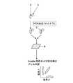
図18は本発明で使用する反応容器を遺伝子多型診断用試薬キットとして使用して遺伝子多型を検出する際の検出方法を概略的に示したものである。ここでは、増幅工程にはPCR法、タイピング工程にはインベーダ(登録商標)法を使用するものとして説明する。
PCR工程では血液などの生体サンプル2にPCR反応試薬4を添加するか、逆にPCR反応試薬4に生体サンプル2を添加する。FIG. 18 schematically shows a detection method for detecting a genetic polymorphism using the reaction container used in the present invention as a genetic polymorphism diagnostic reagent kit. Here, it is assumed that the PCR method is used for the amplification step and the Invader(registered trademark) method is used for the typing step.
In the PCR process, the
PCR反応試薬4は予め調整されたものであり、測定しようとするSNP部位のための複数のプライマーを含み、それにpHを調整するためのpH緩衝液、4種類のデオキシリボヌクレオチド類、熱安定性合成酵素、及びMgCl2、KCl等の塩類などの必要な試薬が添加されている。その他に、界面活性剤や蛋白などの物質を必要に応じて添加することができる。本発明で用いることのある増幅工程のPCR法は、目的とする複数のSNP部位を同時に増幅させるものである。生体サンプルは核酸抽出操作を施しているものであってもよく、核酸抽出操作を施していないものであってもよい。ここで、核酸抽出操作を施していない生体サンプルとは、上述した生体試料、生体由来試料、及び、加熱処理又は凍結処理などの操作によって核酸包含体の膜構造を破壊した状態の生体試料若しくは生体由来試料を含む。核酸抽出操作を施していない生体サンプルから直接PCR法によりそれらのSNP部位を含む複数のゲノムDNAを増幅させる場合には、それらのSNP部位のための複数のプライマーを含む遺伝子増幅反応試薬を生体サンプルに作用させ、サンプル2と混合したときに25℃でのpHが8.5−9.5となる条件下でPCR反応を起こさせる。The
pH緩衝液は、トリス(ヒドロキシメチル)アミノメタンと塩酸、硝酸、硫酸等の鉱酸の組合せのほか、種々のpH緩衝液を使用することができる。pH調整された緩衝液は、PCR反応試薬の中で10mMから100mMの間の濃度で使用するのが好ましい。
プライマーはPCR反応によるDNA合成の開始点として働くオリゴヌクレオチドをいう。プライマーは合成したものであってもよく、生物界から単離したものであってもよい。As the pH buffer solution, various pH buffer solutions can be used in addition to a combination of tris (hydroxymethyl) aminomethane and a mineral acid such as hydrochloric acid, nitric acid and sulfuric acid. The pH-adjusted buffer is preferably used at a concentration between 10 mM and 100 mM in the PCR reaction reagent.
A primer refers to an oligonucleotide that serves as a starting point for DNA synthesis by a PCR reaction. The primer may be synthesized or may be isolated from the living world.
合成酵素はプライマー付加によるDNA合成用の酵素であり、化学合成系も含む。適切な合成酵素としては、E.coliのDNAポリメラーゼI、E.coliのDNAポリメラーゼのクレノーフラグメント、T4DNAポリメラーゼ、TaqDNAポリメラーゼ、T.litoralis DNAポリメラーゼ、TthDNAポリメラーゼ、PfuDNAポリメラーゼ、Hot Start Taq ポリメラーゼ、KOD DNAポリメラーゼ、EX TaqDNAポリメラーゼ、逆転写酵素などがあるが、これらに限定されるものではない。「熱安定性」は、高温下、好ましくは65−95℃でもその活性を保持する化合物の性質を意味する。 Synthetic enzymes are enzymes for DNA synthesis by primer addition and include chemical synthesis systems. Suitable synthases include E. coli. DNA polymerase I, E. coli Klenow fragment of DNA polymerase of E. coli, T4 DNA polymerase, Taq DNA polymerase, T. Examples include, but are not limited to, litoralis DNA polymerase, Tth DNA polymerase, Pfu DNA polymerase, Hot Start Taq polymerase, KOD DNA polymerase, EX Taq DNA polymerase, and reverse transcriptase. “Thermal stability” means the property of a compound that retains its activity at elevated temperatures, preferably at 65-95 ° C.
PCR工程では、生体サンプル2とPCR反応試薬4との混合液を所定の温度サイクルに従ってPCR反応を行なわせる。PCR温度サイクルは、変性、プライマー付着(アニーリング)及びプライマー伸長の3工程を含み、そのサイクルを繰り返すことによりDNAを増幅させる。各工程の一例は、変性工程が94℃で1分間、プライマー付着工程が55℃で1分間、プライマー伸長が72℃で1分間である。生体サンプルは核酸抽出操作を施したものであってもよいが、ここでは核酸抽出操作を施していないものを使用する。核酸抽出操作を施していない生体サンプルであっても、PCR温度サイクルの高温下で核酸が血球や細胞から遊離し、PCR反応に必要な試薬が核酸に接触して反応が進む。 In the PCR step, a PCR reaction is performed on the mixture of the
PCR反応終了後、タイピング試薬としてインベーダ(登録商標)試薬6が添加される。インベーダ(登録商標)試薬6には蛍光を発するフレット(FRET)プローブ及びクリベース(Cleavase:構造特異的DNA分解酵素)が含まれている。フレットプローブはゲノムDNAと全く無関係な配列をもつ蛍光標識オリゴであり、SNPの種類によらず配列は共通であることが多い。After completion of the PCR reaction, Invader(registered trademark)
次に、インベーダ(登録商標)試薬6が添加された反応液を複数のプローブ配置部8に添加して反応をさせる。各プローブ配置部8には、複数のSNP部位のそれぞれに対応してインベーダ(登録商標)プローブとレポータープローブが個別に保持されており、反応液がインベーダ(登録商標)プローブと反応し、そのレポータープローブに対応するSNPが存在すれば蛍光を発する。Next, the reaction solution to which the Invader(registered trademark)
インベーダ(登録商標)法については、特許文献3の段落[0032]から[0034]に詳しく記載されている。
各レポータープローブはそれに対応したSNPの塩基に応じて2種類のものを用意すれば、そのSNPがホモ接合体であるかヘテロ接合体であるかを判別することができる。The Invader(registered trademark) method is described in detail in paragraphs [0032] to [0034] of
If two types of reporter probes are prepared according to the corresponding SNP bases, it can be determined whether the SNP is a homozygote or a heterozygote.
タイピング工程で使用するインベーダ(登録商標)法は、アレル特異的オリゴとタイピング対象のSNPを含むDNAとをハイブリダイゼーションすることによりSNP部位をタイピングする方法であり、タイピング対象のSNPを含むDNAと、タイピング対象のSNPのそれぞれのアレルに特異的な2種類のレポータープローブ及び1種類のインベーダ(登録商標)プローブと、DNAの構造を認識して切断するという特殊なエンドヌクレアーゼ活性を有する酵素とを用いる方法である(特許文献3参照。)。The Invader(registered trademark) method used in the typing step is a method of typing an SNP site by hybridizing an allele-specific oligo and a DNA containing the SNP to be typed, and a DNA containing the SNP to be typed, Two types of reporter probes and one type of Invader(registered trademark) specific to each allele of the SNP to be typed and an enzyme having a special endonuclease activity for recognizing and cleaving the DNA structure are used. It is a method (refer patent document 3).
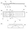
図2は本発明の遺伝子解析装置で使用する反応容器の例である。(A)は正面図、(B)は平面図である。
平板状の基板10の同じ側に試薬収容部14及び反応液よりも比重の低い不揮発性液体収容部16が凹部として形成されている。基板10の同じ側にはさらに、反応部18も形成されている。試薬収容部14と不揮発性液体収容部16はフィルム20で封止されており、試薬と不揮発性液体をノズルで吸入して他の場所に移送する際には、そのフィルム20を取り除いてノズルで吸入するか、又はそのフィルム20をノズルで貫通可能なものとしておいてノズルを貫通させてノズルで吸入する。
基板10の表面は、フィルム20上から、試薬収容部14、不揮発性液体収容部16及び反応部18を被う大きさの剥離可能なシール材22で被われている。FIG. 2 is an example of a reaction vessel used in the gene analysis apparatus of the present invention. (A) is a front view, (B) is a plan view.
On the same side of the
The surface of the
反応液よりも比重の低い不揮発性液体としては、ミネラルオイル(鉱油)、植物油、動物油、シリコーンオイル又はジフェニルエーテルなどを用いることができる。ミネラルオイルはペトロラタムから蒸留により得られる液体の炭化水素混合物であり、流動パラフィン、流動ペトロラタム、ホワイト油などとも呼ばれ、低比重の軽油も含む。動物油としてはタラの肝油、オヒョウ油、ニシン油、オレンジラフィー油又はサメの肝油などを用いることができる。また、植物油としてはカノーラ油、扁桃油、綿実油、トウモロコシ油、オリーブ油、ピーナツ油、ベニバナ油、ゴマ油、大豆油などを用いることができる。
実施例では、不揮発性液体としてミネラルオイルを使用し、以後、不揮発性液体収容部をミネラルオイル収容部と称す。As the non-volatile liquid having a specific gravity lower than that of the reaction liquid, mineral oil (mineral oil), vegetable oil, animal oil, silicone oil, diphenyl ether, or the like can be used. Mineral oil is a liquid hydrocarbon mixture obtained by distillation from petrolatum and is also called liquid paraffin, liquid petrolatum, white oil, etc., and also includes low specific gravity light oil. Examples of animal oils include cod liver oil, halibut oil, herring oil, orange luffy oil, and shark liver oil. As the vegetable oil, canola oil, tonsil oil, cottonseed oil, corn oil, olive oil, peanut oil, safflower oil, sesame oil, soybean oil, and the like can be used.
In the embodiment, mineral oil is used as the non-volatile liquid, and hereinafter, the non-volatile liquid container is referred to as a mineral oil container.
この反応容器の具体的な用途の一例は、反応容器内でサンプルからPCR反応によりDNAを増幅させた後に、インベーダ(登録商標)反応によりSNPを検出する遺伝子多型診断用試薬キットとなったものである。図2を参照して、その遺伝子多型診断用試薬キットとしての実施例を詳細に説明する。An example of a specific use of this reaction container is a genetic polymorphism diagnostic reagent kit for detecting SNP by invader(registered trademark) reaction after amplifying DNA from a sample by PCR reaction in the reaction container It is. With reference to FIG. 2, the Example as the reagent kit for a genetic polymorphism diagnosis is demonstrated in detail.
平板状の基板10aの同じ側に、サンプル注入部12、PCR終了液注入部31、遺伝子増幅試薬収容部30、タイピング試薬収容部14、ミネラルオイル収容部16が凹部として形成されている。基板10aの同じ側にはさらに、増幅反応部32と複数のプローブ配置部18も形成されている。 On the same side of the
サンプル注入部12は核酸抽出操作を施していない生体サンプル又は核酸抽出操作を施した生体サンプルが注入されるものであるが、使用前の状態ではまだサンプルが注入されない空の状態で提供される。PCR終了液注入部31は増幅反応部32でPCR反応を終了した反応液とタイピング試薬とを混合するためのもので、使用前の状態では空の状態で提供される。 The
遺伝子増幅試薬収容部30は複数の多型部位それぞれを挟んで結合する複数のプライマーを含む遺伝子増幅試薬として、PCR反応試薬を2〜300μL収容している。タイピング試薬収容部14は複数の多型部位に対応して調製されたタイピング試薬を10〜300μL程度収容している。ミネラルオイル収容部16は反応液の蒸発を防ぐためのミネラルオイルを20〜300μL収容している。これらの遺伝子増幅試薬収容部30、タイピング試薬収容部14及びミネラルオイル収容部16はノズルで貫通可能なフィルム20で封止されている。そのようなフィルム20は、例えばアルミニウム箔、アルミニウムとPET(ポリエチレンテレフタレート)フィルムなどの樹脂との積層膜などであり、容易に剥がれないように融着や接着により貼りつけられている。
増幅反応部32はPCR反応試薬とサンプルとの混合液に対して遺伝子増幅反応を行なわせるものである。The gene amplification
The
各プローブ配置部18は複数の多型部位のそれぞれに対応して蛍光を発するプローブを個別に保持しており、ミネラルオイル収容部16からのミネラルオイルが分注されたときにそのミネラルオイルを保持できる凹部となっている。各プローブ配置部18の凹部の大きさは、例えば直径が100μm〜2mm、深さが50μm〜1.5mmの円形である。 Each
基板10の表面は、フィルム20上から、サンプル注入部12、PCR終了液注入部31、遺伝子増幅試薬収容部30、タイピング試薬収容部14、ミネラルオイル収容部16、増幅反応部32及びプローブ配置部18を被う大きさの剥離可能なシール材22で被われている。このシール材22もアルミニウム箔、アルミニウムと樹脂との積層膜などであるが、貼りつけ強度はフィルム20よりは弱く、粘着剤などにより剥離可能な程度に貼りつけられている。 The surface of the
基板10は底面側から蛍光を測定するために、低自蛍光性(それ自身からの蛍光発生が少ない性質のこと)で光透過性の樹脂、例えばポリカーボネートなどの素材で形成されている。基板10の厚さは0.3〜4mm、好ましくは1〜2mmである。低自蛍光性の観点から基板10の厚さは薄い方が好ましい。 In order to measure fluorescence from the bottom surface side, the
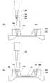
増幅反応部32の一例をその断面を拡大して符号32−1により図3に示す。図3は図2のY−Y線位置での断面図であり、図2には増幅反応部32−1を挟む上下2つの温度調節ユニット62,60も示されている。上部温度調節ユニット62は下降して増幅反応部32と接触するように支持され、下部温度調節ユニット60は上昇して増幅反応部32と接触するように支持されている。 An example of the
増幅反応部32−1は、基板10aに形成された反応室となる流路33と、反応室への液を出し入れするための少なくとも2つのポート34a,34bをその両端に備えたものである。ポート34a,34bはノズル28の先端形状に対応した形状の上方向に開いた開口36a,36bをもち、ノズル28の先端に密着できるようにPDMS(ポリジメチルシロキサン)やシリコーンゴムなどの弾性素材で構成されている。 The amplification reaction section 32-1 includes a
増幅反応部32−1は熱伝導率をよくするためにその部分の基板10aの下面側の肉厚が薄くなっている。その部分の肉厚は、例えば1.2〜0.5mmである。
増幅反応部32−1は基板内に形成された流路状の反応室33と、反応室33が構成されている流路の両端につながり、上方に向かって開口したポート34a,34bを備えている。In order that the amplification reaction part 32-1 may improve thermal conductivity, the thickness of the lower part side of the board |
The amplification reaction unit 32-1 includes a flow channel-shaped
図4(A)は流路状の反応室33の第1の形態33aを表わしたものであり、その反応室33aを構成する流路はポート34a,34bの間に直線状に延びている。
図4(B)は流路状の反応室33の第2の形態33bを表わしたものであり、その反応室33bを構成する流路はポート34a,34bの間で「コ」状に折れ曲がっている。
増幅反応部32の平面状の部分には上下から温度調節ユニット37a,37bが接触して反応室33a,33b内の反応液の温度を制御し、増幅反応を起こさせる。FIG. 4A shows a
FIG. 4B shows a
図3に戻って説明すると、下側の温度調節ユニット60は、加熱冷却素子としてペルチェ素子120を備え、ペルチェ素子120の一方に設けられて増幅反応部32−1の底面と接触するヒートブロック122は熱伝導性の良い金属、例えばアルミニウムから構成され、増幅反応部32−1の底面と接触する部分の形状が増幅反応部32−1の底面と合致する凸部をもった形状に形成されている。ペルチェ素子120の反対側の面には熱伝導率の良い金属、例えばアルミニウムからなる放熱板124が接触している。 Returning to FIG. 3, the lower
増幅反応部32−1の表面側にも加熱冷却素子としてペルチェ素子130が配置され、その一方の面に設けられたヒートブロック132が増幅反応部32−1の表面と接触する部分の形状が増幅反応部32−1の表面と合致する形状に形成されている。ペルチェ素子130の反対側の面には放熱板134が接触している。ヒートブロック132と放熱板134も熱伝導率のよい金属、例えばアルミニウムから構成されている。
図3(B)で増幅反応部32−1が上下の温度調節ユニット62,60で挟まれた状態でペルチェ素子130と120により反応部32−2内の反応液が所定の温度サイクルになるように加熱と冷却が繰り返される。A
In FIG. 3 (B), the reaction liquid in the reaction part 32-2 becomes a predetermined temperature cycle by the
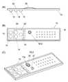
他の形態の増幅反応部を備えた反応容器の例を図5に示す。図5は反応容器の他の例である。(A)は正面図、(B)は平面図、(C)は斜視図である。遺伝子増幅反応部32−2以外の構成は図2に示された反応容器と同じであるので、説明を省略する。
増幅反応部32−2は基板10に形成された反応室となる凹形状のウエル35と、そのウエル35の凹部に入り込んでその一部の空間を占める凸部37aをもち、ウエル35に対して着脱可能な蓋37とからなるものである。図5(C)は蓋37をウエル33から外し、基板10上の特定の場所に載置した状態を示したものである。An example of a reaction vessel provided with another form of amplification reaction unit is shown in FIG. FIG. 5 shows another example of the reaction vessel. (A) is a front view, (B) is a plan view, and (C) is a perspective view. Since the configuration other than the gene amplification reaction unit 32-2 is the same as that of the reaction container shown in FIG.
The amplification reaction part 32-2 has a
遺伝子増幅反応部32−2を図6(A)に具体的に示す。ウエル35は反応容器の基板10と一体成型された一体型のものであってもよく、基板10に接着又は融着されたものであってもよいが、この実施例としては別の形態のものを示す。ウエル35は反応容器の基板10とは別体として形成されている。ウエル35は円盤状であり、その中央部に反応液を収容する反応室となる凹部が形成されている。ウエル35の凹部の肉厚は熱伝導効率をよくするために薄く成形され、その厚さは例えば0.1〜0.5mmである。ウエル35の周辺には厚みが厚くなったフランジ35aが設けられている。基板10にはウエル35を取りつけるための円形の穴があけられ、その穴の周囲には基板10の表面から立ち上がった爪部11aが形成されている。ウエル35は基板10のその穴に基板10の表面側にウエルの凹部が向くようにして嵌め込まれ、フランジ35aが爪部11aと係合することにより基板10に固定されている。 The gene amplification reaction part 32-2 is specifically shown in FIG. The well 35 may be an integral type integrally formed with the
蓋37に設けられた凸部37aはウエル35の凹部の空間の一部を占めるためのものであり、その凸部37aの外周の直径がウエル35の凹部の内径と一致するように形成され、蓋37はその凸部37aによってウエル35の凹部に密閉状態で着脱可能に取りつけられる。蓋37の凸部37aの内側は開口し、その開口部の縁に切込みが形成されていることによって係合部となる突起37bが形成されている。この反応容器による熱処理の際には、凸部37aの内側にヒートブロックの凸部が挿入されて接触して熱伝導が行なわれる。 The
ウエル35に所定量の反応液38を入れ、蓋37でウエル35を閉じると、凸部37aの一部が反応液38と接触するか、又はウエル35の凹部の空間ができるだけ小さくなるように、ウエル35の寸法と凸部37aの寸法が設定されている。 When a predetermined amount of the
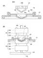
図6(B)はこのようにウエル35に反応液38が入れられ、蓋37で閉じられて、PCR反応などで温度制御を行うときの状態を示している。反応部32−2の下側にはヒートブロック60が接触させられ、反応部32−2の上側にはヒートブロック62が接触させられる。 FIG. 6B shows a state in which the
下側の温度調節ユニット60は、加熱冷却素子としてペルチェ素子120を備え、ペルチェ素子120の一方に設けられてウエル35の底面と接触するヒートブロック122は熱伝導性の良い金属、例えばアルミニウムから構成され、ウエル35の底面と接触する部分の形状がウエルの底面と合致する凹部をもった形状に形成されている。ペルチェ素子120の反対側の面には熱伝導率の良い金属、例えばアルミニウムからなる放熱板124が接触している。 The lower
反応部32−2の蓋37側にも加熱冷却素子としてペルチェ素子130が配置され、その一方の面に設けられたヒートブロック132が蓋37と接触する部分の形状が蓋37と合致する凸部をもった形状に形成されている。ペルチェ素子130の反対側の面には放熱板134が接触している。ヒートブロック132と放熱板137も熱伝導率のよい金属、例えばアルミニウムから構成されている。
図6(B)の状態でペルチェ素子130と120により反応部32−2内の反応液が所定の温度サイクルになるように加熱と冷却が繰り返される。A convex portion in which a
In the state of FIG. 6B, heating and cooling are repeated by the
図7は上記の反応容器を試薬キットとして用い、生体サンプルのSNPを検出するための簡易型遺伝子解析装置に本発明を適用した一実施例を示したものである。
装置内にヒータとして上下に一対の温度調節ユニット60と62が配置されている。反応容器装着部は、下側温度調節ユニット60上に図2に示された反応容器41がスライドして所定の位置に位置決めされる案内部が形成されていることにより構成されている。反応容器装着部には反応容器41にサンプルが注入されたものが5枚平行に並べて設置される。これらの温度調節ユニット60,62は、矢印で示されるY方向に移動することができる。FIG. 7 shows an embodiment in which the present invention is applied to a simple genetic analyzer for detecting SNP in a biological sample using the above reaction container as a reagent kit.
A pair of
上下の温度調節ユニット60,62は増幅反応部32の温度を所定の温度サイクルになるように制御する増幅反応温度制御部を構成している。また、両温度調節ユニット60,62はまた、プローブ配置部18の温度をDNAとプローブとを反応させる温度に制御するタイピング反応温度制御部も構成している。増幅反応温度制御部とタイピング反応温度制御部は、図1ではそれぞれ符号120,110で示されている。増幅反応温度制御部の温度は、例えば94℃、55℃及び72℃の3段階にその順に変化させられ、そのサイクルが繰り返されるように設定されている。タイピング反応温度制御部の温度は、例えば63℃に設定されている。 The upper and lower
増幅反応温度制御部を構成している温度調節ユニット60,62の部分を図8と図9により詳細に示す。この実施例では5個の反応容器10が装着されるようになっており、温度調節ユニット60,62の組は反応容器10ごとに設けられている。上部温度調節ユニット62は反応容器装着部とは別の部材に上下動可能に支持されており、下部温度調節ユニット60は反応容器装着部に上下動可能に支持されている。 The
5個の上部温度調節ユニット62を同時に下降させるために、各上部温度調節ユニット62の上面に軸144が当接しており、それらの5本の軸144の上端を固定する基板143の上面に駆動用の棒ネジ146の下端が当接している。
下部温度調節ユニット60はそれぞれの下面側が回動可能なジョイント142により共通のレバー141の先端側に支持されている。レバー141は軸140により回動可能に支持され、レバー141の基端部には上部温度調節ユニット62を下降させるための基板143と一体化された連結部材の下端部が当接している。In order to lower the five upper
The lower
棒ネジ146が上がっているときは温度調節ユニット60,62が反応容器10の増幅反応部から離れるように、付勢手段又は自重により温度調節ユニット60が所定の位置まで下降し、温度調節ユニット62が所定の位置まで上昇している。棒ネジ146が駆動されて下降すると基板143を押し下げ、それに伴って上部温度調節ユニット62が下降させられ、同時に下部温度調節ユニット60が上昇させられる。下部温度調節ユニット60は回動可能なジョイント142によりレバー141に支持されているので、反応容器10の増幅反応部と良好に密着することができる。 When the
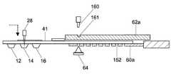
図10に示されるように、温度調節ユニット60,62のうち、タイピング反応温度制御部を構成する温度調節部は反応容器41が装着部に装着された状態でプローブ配置部の下部に位置する下部温度調節ユニット60aと、プローブ配置部の上部に位置することのできる上部温度調節ユニット62aとからなる。下部温度調節ユニット60aは位置が固定されているが、上部温度調節ユニット62aはプローブ配置部の上部を覆う位置(図10の状態)とその位置から外れた位置との間で水平方向にスライドして移動可能に支持されている。 As shown in FIG. 10, among the
上部温度調節ユニット62aはプローブ配置部の上部を覆う位置に移動させられる前に予め温度調節されている。その温度は、プローブ配置部の温度をゲノムDNAとタイピング試薬との反応液がプローブ配置部のプローブと反応するために必要な温度とするために必要な温度である。 The upper
上部温度調節ユニット62aの表面には凹部161が形成され、分注部の送液アーム66にはその凹部161と係合できるピン160が設けられている。その凹部161にピン160を係合させ、送液アーム66を水平方向に移動させることにより、上部温度調節ユニット62aをスライド動作させることができる。
下部温度調節ユニット60aはプローブ配置部に対応する位置にのみ開口152をもっている。A
The lower
反応容器41のプローブ配置部に反応液とタイピング試薬を分注するときは、上部温度調節ユニット62aがプローブ配置部の上部を覆う位置から取り除かれた位置に移動させておき、分注後に上部温度調節ユニット62aをプローブ配置部の上部を覆う位置に移動させる。 When dispensing the reaction solution and the typing reagent to the probe placement part of the
図7に戻って説明すると、ノズル28による液の移送や吸入、吐出を行なうために、分注部としてX方向、Y方向及びZ方向に移動する送液アーム66が設けられており、送液アーム66はノズル28を備えている。分注部は図1では符号112で示されている。 Returning to FIG. 7, in order to transfer, suck, and discharge the liquid by the
図11はノズル28の先端部を表わしたものである。ノズル28はその先端に使い捨て可能な分注チップ70が着脱可能に装着される。(A)はノズル28に分注チップ70が装着されていない状態、(B)はノズル28に分注チップ70が装着された状態を表わしている。ノズル28は分注チップ70内への液の吸入と吐出を行なう。そのため、ノズル28はその先端に分注チップ70を装着する外形寸法をもつ装着部28aと、その装着部28aの先端にあって、分注する液と接触しない長さで装着部28aよりも外形寸法の小さい突出部28bとを備えている。
ノズル28は液の吸入と吐出を行なうときは先端に分注チップ70を装着する。FIG. 11 shows the tip of the
The
図10に示されるように、温度調節ユニット60aの下部には蛍光検出を行なう蛍光検出部64が配置されており、蛍光検出部64は反応容器41の下面側から温度調節ユニット60aの開口152を介してプローブ配置部に励起光を照射し、反応容器41の下面側で温度調節ユニット60aの開口152を介してプローブ配置部からの蛍光を検出する。蛍光検出部64は図10の矢印X方向に移動してブローブ配置部18からの蛍光を検出する。反応容器装着部によるプローブ配置部18のY方向移動と、蛍光検出部64のX方向移動により各ブローブでの蛍光検出を行なう。 As shown in FIG. 10, a
図7に戻って説明すると、温度調節ユニット60,62、蛍光検出部64及び送液アーム66の動作を制御するために、それらの近くに制御部118が配置されている。制御部118はCPUを備えて、動作のためのプログラムを保持している。制御部118は温度調節ユニット60,62により実現されるタイピング反応温度制御部110や増幅反応温度制御部120の温度制御、蛍光検出部64の検出動作、並びに分注部112の送液アーム66の分注動作及び増幅反応終了液の回収動作を制御する。 Returning to FIG. 7, in order to control the operation of the
図12は蛍光検出部64を詳細に示したものである。蛍光検出部64は励起光源として473nmのレーザ光を発するレーザダイオード(LD)や発光ダイオード(LED)92を備え、そのレーザ光を反応容器41のプローブ配置部の底面に集光して照射する一対のレンズ94,96を備えている。レンズ94はレーザダイオード92からのレーザ光を集光して平行光にするものであり、レンズ96は平行にされたレーザ光を反応容器41の底面に収束させて照射する対物レンズである。対物レンズ96はまた、反応容器41から発生する蛍光を集光するレンズとしても作用する。一対のレンズ94,96の間にはダイクロイックミラー98が設けられており、ダイクロイックミラー98は励起光を透過させ、蛍光を反射させるように波長特性が設定されている。ダイクロイックミラー98の反射光(蛍光)の光路上にはさらにダイクロイックミラー100が配置されている。ダイクロイックミラー100は525nmの光を反射し605nmの光を透過するように波長特性が設定されている。ダイクロイックミラー100による反射光の光路上には525nmの蛍光を検出するようにレンズ102と光検出器104が配置され、ダイクロイックミラー100による透過光の光路上には605nmの蛍光を検出するようにレンズ106と光検出器108が配置されている。この2つの光検出器104,108による2種類の蛍光検出により、各プローブ配置位置に固定されたインベーダ(登録商標)プローブに対応したSNPの有無と、そのSNPがホモ接合体であるかヘテロ接合体であるかが検知される。標識蛍光体としては、例えばFAM、ROX、VIC、TAMRA、Redmond Redなどを使用することができる。FIG. 12 shows the
図12の検出器64は1光源による励起光で励起し、2波長の蛍光を測定するように構成されているが、検出器64としては2波長の蛍光測定のために異なる励起波長で励起できるように2光源を使用するように構成してもよい。The
この実施例における反応容器の使用方法を示す。ここでは、増幅反応部32として図3に示されたものを使用した場合を示す。
図13に示されるように、使用時にシール材22が剥がされる。タイピング試薬収容部14、ミネラルオイル収容部18及び遺伝子増幅試薬収容部30を封止しているフィルム20は剥がされないでそのまま残っている。The usage method of the reaction container in this Example is shown. Here, a case where the
As shown in FIG. 13, the sealing
サンプル注入部12にサンプル25がピペット26などにより0.5〜2μL、例えば1μL注入される。サンプルは核酸抽出操作を施していない生体サンプル、例えば血液である。サンプルは核酸抽出操作を施した生体サンプルであってもよい。サンプル注入後、 この反応容器が遺伝子解析装置に装着される。
また、遺伝子解析装置には使い捨て可能な分注チップがセットされる。The
A disposable dispensing tip is set in the gene analyzer.
遺伝子解析装置において、分注装置がノズル28に使い捨て可能な分注チップを装着する。ノズル28はその先端に分注チップを装着して分注動作を行なう。
ノズル28がフィルム20を貫通して遺伝子増幅試薬収容部30に挿入されてPCR反応試薬が吸入され、PCR反応試薬はそのノズル28によりサンプル注入部12に2〜20μL移送される。サンプル注入部12ではノズル28による吸入と吐出が繰り返されることにより、サンプル反応液とPCR反応試薬が混合されてPCR反応液となる。In the gene analyzer, the dispensing device attaches a disposable dispensing tip to the
The
次に、そのPCR反応液がノズル28により吸入されるが、このとき図14に示されるように、分注チップ内にミネラルオイル39、PCR反応液38、ミネラルオイル39の順に吸引し、分注チップ内では上層にミネラルオイル39、中間層にPCR反応液38、下層にミネラルオイルの3層になる状態にする。 Next, the PCR reaction liquid is sucked by the
次に、増幅反応部32へ注入される。すなわち、図15(A)に示されるようにノズル28が増幅反応部32の一方のポート34aに挿入されてその分注チップ内の3層の液がそのまま注入されて、注入された液は図15(B)に示される状態になる。この状態は、注入されたPCR反応液38が、増幅部の遺伝子増幅反応温度制御領域にのみ配置される状態であり、そのような状態になるように制御装置により分注装置でのミネラルオイル39、PCR反応液38及びミネラルオイル39の分注量が制御される。また、この状態は、増幅反応部32での反応中にPCR反応液38が蒸発するのを防ぐために、PCR反応液38の両端がミネラルオイル39で閉じられた状態となる。 Next, it is injected into the
PCR反応終了後、PCR反応終了液38aがポート34a又は34aからノズル28により回収される。このとき、ミネラルオイル39/PCR反応終了液38a/ミネラルオイル39の3層のまま、又はミネラルオイル39/PCR反応終了液38aの2層で回収される。ここで、回収を容易にするために、図16(A),(B)に示されるように、増幅反応部32の一方のポート34aからミネラルオイルが注入されてもよい。PCR反応終了液38aは他方のポート34bに押しやられる。そこで、そのポート34bにノズル28が挿入され、PCR反応終了液38aがノズル28に吸入される。PCR反応終了液38aの回収に際しては、ノズル28にはミネラルオイル39/PCR反応終了液38a/ミネラルオイル39の3層を吸入してもよく、又はミネラルオイル39/PCR反応終了液38aの2層を吸入してもよい。ポート34a,34bはその開口36a,36bの形状がノズル28の形状に合わせて形成され、かつ弾性素材で形成されているので、ノズル28がポート34a,34bに密着して液漏れを防ぎ、PCR反応液の注入と回収の操作が容易である。
ここで、ポート34aから注入する液体はミネラルオイル40に限らず、他の液体であってもよく、好ましくは比重が反応液と同じか反応液よりも低い液体である。After completion of the PCR reaction, the PCR
Here, the liquid injected from the
ノズル28により増幅反応部32から回収された反応終了後のPCR反応終了液38aはPCR終了液注入部31に移送されて注入される。このとき、PCR終了液注入部31 には回収した液のうちのミネラルオイル39層を捨ててPCR反応終了液38aのみ分注してもよいし、そのままミネラルオイル39ごと分注してもよい。ミネラルオイル39は次工程の反応を阻害しない。 The PCR
次に、図17に示されるように、ノズル28がフィルム20を貫通してタイピング試薬収容部14に挿入されてタイピング試薬が吸入され、タイピング試薬はそのノズル28によりPCR終了液注入部31に移送されて注入される。PCR終了液注入部31ではノズル28による吸入と吐出が繰り返されることにより、PCR反応終了液とタイピング試薬が混合される。 Next, as shown in FIG. 17, the
その後、PCR反応液とタイピング試薬との反応液がノズル28により各プローブ配置部18へ0.5〜4μLずつ分注される。各プローブ配置部18にはノズル28によりミネラルオイル収容部16からミネラルオイルが0.5〜10μLずつ分注される。プローブ配置部18へのミネラルオイルの分注は、プローブ配置部18への反応液の分注前であってもよい。各プローブ配置部18ではミネラルオイルが反応液の表面を被い、検出装置のタイピング反応温度制御部での加熱を伴なうタイピング反応時間中の反応液の蒸発を防止する。
各プローブ配置部18では反応液がプローブと反応して所定のSNPがあればそのプローブから蛍光が発せられる。蛍光は基板10の裏面側から励起光を照射することにより検出する。Thereafter, the reaction solution of the PCR reaction solution and the typing reagent is dispensed by the
In each
以下、各反応試薬の組成を示して、本発明を詳細に説明するが、本発明の技術的範囲はこれらの反応容器に限定されるものではない。
PCR反応試薬は既知のものであり、例えば特許文献3の段落[0046]に記載されているような、プライマー、DNAポリメラーゼ及びTaqStart (CLONTECH Laboratories社製)を含む反応試薬を使用することができる。また、PCR反応試薬にはAmpDirect(島津製作所製)が混入されていてもよい。プライマーは、例えば、特許文献3の表1に記載されているSNP ID1〜20、配列番号を1〜40などを使用することができる。Hereinafter, although the composition of each reaction reagent is shown and the present invention is described in detail, the technical scope of the present invention is not limited to these reaction vessels.
PCR reaction reagents are known, and for example, reaction reagents including primers, DNA polymerase, and TaqStart (manufactured by CLONTECH Laboratories) as described in paragraph [0046] of
タイピング試薬としてインベーダ(登録商標)試薬を使用する。そのインベーダ(登録商標)試薬としては、インベーダ(登録商標)アッセイキット(Third Wave Technology社製)を使用する。例えば、シグナルバッファー、フレットプローブ、構造特異的DNA分解酵素及びアレル特異的プローブを特許文献3の段落[0046]に記載されているような濃度に調製されたものである。Invader(registered trademark) reagent is used as a typing reagent. As the Invader(registered trademark) reagent, anInvader (registered trademark) assay kit (manufactured by Third Wave Technology) is used. For example, a signal buffer, a fret probe, a structure-specific DNA degrading enzyme, and an allele-specific probe are prepared at concentrations as described in paragraph [0046] of
本発明は種々の化学反応の測定のほか、例えば遺伝子解析の研究や臨床分野において、種々の自動分析に利用することができ、例えば、人間を初めとして、動物や植物のゲノムDNAの多型、特にSNPなどを検出することができ、さらにその結果を用いて病気罹患率の診断や、投与薬剤の種類と効果及び副作用との関係などの診断のほか、動物や植物の品種判定、感染症診断(感染菌の型判定)などを行なうのにも利用することができる。 In addition to measurement of various chemical reactions, the present invention can be used for various automatic analyzes in, for example, genetic analysis research and clinical fields. For example, polymorphisms of genomic DNA of animals and plants including humans, In particular, SNPs can be detected, and the results are used to diagnose disease prevalence, diagnose the relationship between the type of drug administered, effects and side effects, animal and plant breeding, and infection diagnosis It can also be used for (type determination of infecting bacteria).
2 サンプル
4 PCR反応試薬
6 インベーダ(登録商標)試薬
8 プローブ配置部
10a 基板
12 サンプル注入部
14 タイピング試薬収容部
16 ミネラルオイル収容部
18 プローブ配置部
20 フィルム
22 シール材
28 分注ノズル
30 遺伝子増幅試薬収容部
31 PCR終了液注入部
32 増幅反応部
34a,34b ポート
36a,36b ポートの開口
38 PCR反応液
38a PCR反応終了液
41 反応容器
60,62 温度調節ユニット
60a,62a タイピング反応温度制御部の温度調節ユニット
64 蛍光検出部
66 送液アーム
70 分注チップ
110 タイピング反応温度制御部
112 分注部
118 制御部2
Claims (6)
Translated fromJapanese核酸とタイピング試薬との反応液を前記プローブ配置部のプローブと反応させるために前記プローブ配置部の温度を制御するタイピング反応温度調節部と、
前記反応液を前記各プローブ配置部へ移送する分注部と、
前記各プローブ配置部に励起光を照射して蛍光を検出する蛍光検出装置と、
タイピング反応温度調節部の温度制御、前記分注部の分注動作、並びに前記蛍光検出装置の検出動作を制御する制御部と、を備え、
前記タイピング反応温度調節部の少なくとも一部は、前記反応容器が前記装着部に装着された状態で、前記プローブ配置部を温度調節する位置とその位置から外れた位置との間で移動可能に支持されており、
前記タイピング反応温度調節部の移動可能な部分は水平方向にスライド可能に支持され、前記分注部の一部と係合し、分注部の移動によりスライド動作がなされるようになっている遺伝子解析装置。A mounting part for mounting a reaction container for genetic polymorphism diagnosis provided with a plurality of probe placement parts each holding a probe emitting fluorescence corresponding to each of a plurality of polymorphic sites;
A typing reaction temperature control unit for controlling the temperature of the probe placement unit in order to react the reaction solution of the nucleic acid and the typing reagent with the probe of the probe placement unit;
A dispensing part for transferring the reaction solution to each probe placement part;
A fluorescence detection device for detecting fluorescence by irradiating each probe placement portion with excitation light;
A temperature control of the typing reaction temperature control unit, a dispensing operation of the dispensing unit, and a control unit for controlling the detection operation of the fluorescence detection device,
At least a part of the typing reaction temperature adjustment unit is supported so as to be movable between a position where the temperature of the probe placement unit is adjusted and a position outside the position when the reaction container is mounted on the mounting unit. Hasbeen
The movable part of the typing reaction temperature control unit is supported so as to be slidable in the horizontal direction, engages with a part of the dispensing unit, and is slidable by movement of the dispensing unit . Analysis device.
Priority Applications (1)
| Application Number | Priority Date | Filing Date | Title |
|---|---|---|---|
| JP2005378507AJP4751719B2 (en) | 2005-12-28 | 2005-12-28 | Genetic analyzer |
Applications Claiming Priority (1)
| Application Number | Priority Date | Filing Date | Title |
|---|---|---|---|
| JP2005378507AJP4751719B2 (en) | 2005-12-28 | 2005-12-28 | Genetic analyzer |
Publications (2)
| Publication Number | Publication Date |
|---|---|
| JP2007175003A JP2007175003A (en) | 2007-07-12 |
| JP4751719B2true JP4751719B2 (en) | 2011-08-17 |
Family
ID=38300820
Family Applications (1)
| Application Number | Title | Priority Date | Filing Date |
|---|---|---|---|
| JP2005378507AExpired - Fee RelatedJP4751719B2 (en) | 2005-12-28 | 2005-12-28 | Genetic analyzer |
Country Status (1)
| Country | Link |
|---|---|
| JP (1) | JP4751719B2 (en) |
Families Citing this family (4)
| Publication number | Priority date | Publication date | Assignee | Title |
|---|---|---|---|---|
| WO2009054473A1 (en)* | 2007-10-26 | 2009-04-30 | Toppan Printing Co., Ltd. | Reaction chip, reaction method, temperature controlling unit for gene treating apparatus and gene treating apparatus |
| JP5239353B2 (en)* | 2008-01-22 | 2013-07-17 | 凸版印刷株式会社 | Temperature control apparatus and temperature control method |
| JP6828192B2 (en)* | 2018-01-10 | 2021-02-10 | 株式会社日立ハイテク | Automatic analyzer |
| US20220099624A1 (en)* | 2020-09-30 | 2022-03-31 | Icare Diagnostics International Co. Ltd. | Nucleic acid detection host and nucleic acid detection device |
Family Cites Families (7)
| Publication number | Priority date | Publication date | Assignee | Title |
|---|---|---|---|---|
| CA2031912A1 (en)* | 1989-12-22 | 1991-06-23 | Robert Fred Pfost | Heated cover device |
| KR100236506B1 (en)* | 1990-11-29 | 2000-01-15 | 퍼킨-엘머시터스인스트루먼츠 | Apparatus for polymerase chain reaction |
| JPH08196299A (en)* | 1995-01-26 | 1996-08-06 | Tosoh Corp | Thermal cycling reactor and reaction vessel used therefor |
| JP3182527B2 (en)* | 1996-09-03 | 2001-07-03 | 株式会社ヤトロン | Chemiluminescence measurement method and kit |
| JP4639558B2 (en)* | 2001-09-07 | 2011-02-23 | 株式会社島津製作所 | Microwell chip |
| JP4695851B2 (en)* | 2003-07-10 | 2011-06-08 | シチズンホールディングス株式会社 | Micro chemical chip temperature controller |
| JP2005204592A (en)* | 2004-01-23 | 2005-08-04 | Kubota Corp | Fully automated gene analysis system |
- 2005
- 2005-12-28JPJP2005378507Apatent/JP4751719B2/ennot_activeExpired - Fee Related
Also Published As
| Publication number | Publication date |
|---|---|
| JP2007175003A (en) | 2007-07-12 |
Similar Documents
| Publication | Publication Date | Title |
|---|---|---|
| JP4619403B2 (en) | Reaction vessel and reaction vessel processing apparatus | |
| JP4527565B2 (en) | Reaction vessel | |
| JP2007178328A (en) | Reaction container kit and reaction container processing apparatus | |
| JP4643277B2 (en) | Reaction vessel, gene polymorphism detection method and apparatus | |
| JP4751718B2 (en) | Genetic analyzer | |
| JP5086559B2 (en) | Reaction vessel and reaction vessel processing apparatus | |
| JP4621247B2 (en) | Dispensing method and reaction vessel processing apparatus in reaction vessel | |
| JP4527582B2 (en) | Reaction vessel processing equipment | |
| JP4714475B2 (en) | Reaction vessel, gene polymorphism detection method and apparatus | |
| JPWO2006054690A1 (en) | Genetic polymorphism detection method, diagnostic method, and apparatus and test reagent kit therefor | |
| JP4580981B2 (en) | Genetic polymorphism diagnostic equipment | |
| JP4562768B2 (en) | Nonvolatile liquid dispensing method and reaction vessel processing apparatus in reaction vessel | |
| JP4751721B2 (en) | Genetic analyzer | |
| JP4751719B2 (en) | Genetic analyzer | |
| JP4928781B2 (en) | Reaction vessel and reaction vessel processing apparatus | |
| JP4751720B2 (en) | Genetic analyzer | |
| JP4792278B2 (en) | Reaction vessel and reaction vessel processing apparatus | |
| JP4792277B2 (en) | Reaction vessel and reaction vessel processing apparatus | |
| JP4711716B2 (en) | Reaction vessel processing equipment | |
| JP4751633B2 (en) | Method for collecting reaction liquid in reaction vessel | |
| JP4697781B2 (en) | Reaction vessel processing equipment | |
| JP4759299B2 (en) | Reaction vessel processing equipment | |
| JP4659501B2 (en) | Reaction vessel processing equipment | |
| JP4714497B2 (en) | Reaction vessel processing equipment | |
| JP2006223126A (en) | Reaction vessel, genetic polymorphism detection method and apparatus, and diagnostic method and apparatus |
Legal Events
| Date | Code | Title | Description |
|---|---|---|---|
| A521 | Request for written amendment filed | Free format text:JAPANESE INTERMEDIATE CODE: A523 Effective date:20080304 | |
| A711 | Notification of change in applicant | Free format text:JAPANESE INTERMEDIATE CODE: A711 Effective date:20080304 | |
| A521 | Request for written amendment filed | Free format text:JAPANESE INTERMEDIATE CODE: A821 Effective date:20080304 | |
| A621 | Written request for application examination | Free format text:JAPANESE INTERMEDIATE CODE: A621 Effective date:20080605 | |
| A131 | Notification of reasons for refusal | Free format text:JAPANESE INTERMEDIATE CODE: A131 Effective date:20110301 | |
| A521 | Request for written amendment filed | Free format text:JAPANESE INTERMEDIATE CODE: A523 Effective date:20110419 | |
| TRDD | Decision of grant or rejection written | ||
| A01 | Written decision to grant a patent or to grant a registration (utility model) | Free format text:JAPANESE INTERMEDIATE CODE: A01 Effective date:20110517 | |
| A01 | Written decision to grant a patent or to grant a registration (utility model) | Free format text:JAPANESE INTERMEDIATE CODE: A01 | |
| A61 | First payment of annual fees (during grant procedure) | Free format text:JAPANESE INTERMEDIATE CODE: A61 Effective date:20110523 | |
| R150 | Certificate of patent or registration of utility model | Free format text:JAPANESE INTERMEDIATE CODE: R150 | |
| FPAY | Renewal fee payment (event date is renewal date of database) | Free format text:PAYMENT UNTIL: 20140527 Year of fee payment:3 | |
| S111 | Request for change of ownership or part of ownership | Free format text:JAPANESE INTERMEDIATE CODE: R313117 | |
| R360 | Written notification for declining of transfer of rights | Free format text:JAPANESE INTERMEDIATE CODE: R360 | |
| R360 | Written notification for declining of transfer of rights | Free format text:JAPANESE INTERMEDIATE CODE: R360 | |
| R371 | Transfer withdrawn | Free format text:JAPANESE INTERMEDIATE CODE: R371 | |
| S111 | Request for change of ownership or part of ownership | Free format text:JAPANESE INTERMEDIATE CODE: R313117 | |
| R350 | Written notification of registration of transfer | Free format text:JAPANESE INTERMEDIATE CODE: R350 | |
| S533 | Written request for registration of change of name | Free format text:JAPANESE INTERMEDIATE CODE: R313533 | |
| R350 | Written notification of registration of transfer | Free format text:JAPANESE INTERMEDIATE CODE: R350 | |
| LAPS | Cancellation because of no payment of annual fees |