JP4751269B2 - Illumination device, display device including the same, and portable electronic device - Google Patents
Illumination device, display device including the same, and portable electronic deviceDownload PDFInfo
- Publication number
- JP4751269B2 JP4751269B2JP2006217124AJP2006217124AJP4751269B2JP 4751269 B2JP4751269 B2JP 4751269B2JP 2006217124 AJP2006217124 AJP 2006217124AJP 2006217124 AJP2006217124 AJP 2006217124AJP 4751269 B2JP4751269 B2JP 4751269B2
- Authority
- JP
- Japan
- Prior art keywords
- light
- phosphor
- liquid crystal
- light source
- crystal display
- Prior art date
- Legal status (The legal status is an assumption and is not a legal conclusion. Google has not performed a legal analysis and makes no representation as to the accuracy of the status listed.)
- Expired - Fee Related
Links
- 238000005286illuminationMethods0.000titleclaimsdescription17
- OAICVXFJPJFONN-UHFFFAOYSA-NPhosphorusChemical compound[P]OAICVXFJPJFONN-UHFFFAOYSA-N0.000claimsdescription61
- 239000011347resinSubstances0.000claimsdescription28
- 229920005989resinPolymers0.000claimsdescription28
- 239000011324beadSubstances0.000claimsdescription13
- 239000006185dispersionSubstances0.000claimsdescription12
- 238000007789sealingMethods0.000claimsdescription10
- 239000003086colorantSubstances0.000claimsdescription9
- 239000000049pigmentSubstances0.000claimsdescription5
- 229920002799BoPETPolymers0.000claimsdescription4
- 230000003287optical effectEffects0.000claimsdescription3
- 239000004973liquid crystal related substanceSubstances0.000description96
- 230000002087whitening effectEffects0.000description15
- 244000172533Viola sororiaSpecies0.000description7
- 238000006243chemical reactionMethods0.000description5
- 239000000047productSubstances0.000description4
- NIXOWILDQLNWCW-UHFFFAOYSA-Nacrylic acid groupChemical groupC(C=C)(=O)ONIXOWILDQLNWCW-UHFFFAOYSA-N0.000description3
- 239000012466permeateSubstances0.000description2
- 229920000139polyethylene terephthalatePolymers0.000description2
- 239000005020polyethylene terephthalateSubstances0.000description2
- 239000000843powderSubstances0.000description2
- 239000004593EpoxySubstances0.000description1
- 229910052693EuropiumInorganic materials0.000description1
- UCKMPCXJQFINFW-UHFFFAOYSA-NSulphideChemical compound[S-2]UCKMPCXJQFINFW-UHFFFAOYSA-N0.000description1
- 230000005540biological transmissionEffects0.000description1
- 230000001413cellular effectEffects0.000description1
- 230000007423decreaseEffects0.000description1
- 238000010586diagramMethods0.000description1
- OGPBJKLSAFTDLK-UHFFFAOYSA-Neuropium atomChemical compound[Eu]OGPBJKLSAFTDLK-UHFFFAOYSA-N0.000description1
- 230000005284excitationEffects0.000description1
- WABPQHHGFIMREM-UHFFFAOYSA-Nlead(0)Chemical compound[Pb]WABPQHHGFIMREM-UHFFFAOYSA-N0.000description1
- 239000000463materialSubstances0.000description1
- 239000000203mixtureSubstances0.000description1
- 150000004767nitridesChemical class0.000description1
- 229920000515polycarbonatePolymers0.000description1
- 239000004417polycarbonateSubstances0.000description1
- -1polyethylene terephthalatePolymers0.000description1
- 239000003566sealing materialSubstances0.000description1
- 229910052710siliconInorganic materials0.000description1
- 239000010703siliconSubstances0.000description1
- 239000000126substanceSubstances0.000description1
- 238000002834transmittanceMethods0.000description1
Images


Classifications
- G—PHYSICS
- G02—OPTICS
- G02B—OPTICAL ELEMENTS, SYSTEMS OR APPARATUS
- G02B6/00—Light guides; Structural details of arrangements comprising light guides and other optical elements, e.g. couplings
- G02B6/0001—Light guides; Structural details of arrangements comprising light guides and other optical elements, e.g. couplings specially adapted for lighting devices or systems
- G02B6/0011—Light guides; Structural details of arrangements comprising light guides and other optical elements, e.g. couplings specially adapted for lighting devices or systems the light guides being planar or of plate-like form
- G02B6/0066—Light guides; Structural details of arrangements comprising light guides and other optical elements, e.g. couplings specially adapted for lighting devices or systems the light guides being planar or of plate-like form characterised by the light source being coupled to the light guide
- G02B6/0073—Light emitting diode [LED]
- G—PHYSICS
- G02—OPTICS
- G02F—OPTICAL DEVICES OR ARRANGEMENTS FOR THE CONTROL OF LIGHT BY MODIFICATION OF THE OPTICAL PROPERTIES OF THE MEDIA OF THE ELEMENTS INVOLVED THEREIN; NON-LINEAR OPTICS; FREQUENCY-CHANGING OF LIGHT; OPTICAL LOGIC ELEMENTS; OPTICAL ANALOGUE/DIGITAL CONVERTERS
- G02F1/00—Devices or arrangements for the control of the intensity, colour, phase, polarisation or direction of light arriving from an independent light source, e.g. switching, gating or modulating; Non-linear optics
- G02F1/01—Devices or arrangements for the control of the intensity, colour, phase, polarisation or direction of light arriving from an independent light source, e.g. switching, gating or modulating; Non-linear optics for the control of the intensity, phase, polarisation or colour
- G02F1/13—Devices or arrangements for the control of the intensity, colour, phase, polarisation or direction of light arriving from an independent light source, e.g. switching, gating or modulating; Non-linear optics for the control of the intensity, phase, polarisation or colour based on liquid crystals, e.g. single liquid crystal display cells
- G02F1/133—Constructional arrangements; Operation of liquid crystal cells; Circuit arrangements
- G02F1/1333—Constructional arrangements; Manufacturing methods
- G02F1/1335—Structural association of cells with optical devices, e.g. polarisers or reflectors
- G02F1/1336—Illuminating devices
- G02F1/133617—Illumination with ultraviolet light; Luminescent elements or materials associated to the cell
- G—PHYSICS
- G02—OPTICS
- G02F—OPTICAL DEVICES OR ARRANGEMENTS FOR THE CONTROL OF LIGHT BY MODIFICATION OF THE OPTICAL PROPERTIES OF THE MEDIA OF THE ELEMENTS INVOLVED THEREIN; NON-LINEAR OPTICS; FREQUENCY-CHANGING OF LIGHT; OPTICAL LOGIC ELEMENTS; OPTICAL ANALOGUE/DIGITAL CONVERTERS
- G02F1/00—Devices or arrangements for the control of the intensity, colour, phase, polarisation or direction of light arriving from an independent light source, e.g. switching, gating or modulating; Non-linear optics
- G02F1/01—Devices or arrangements for the control of the intensity, colour, phase, polarisation or direction of light arriving from an independent light source, e.g. switching, gating or modulating; Non-linear optics for the control of the intensity, phase, polarisation or colour
- G02F1/13—Devices or arrangements for the control of the intensity, colour, phase, polarisation or direction of light arriving from an independent light source, e.g. switching, gating or modulating; Non-linear optics for the control of the intensity, phase, polarisation or colour based on liquid crystals, e.g. single liquid crystal display cells
- G02F1/133—Constructional arrangements; Operation of liquid crystal cells; Circuit arrangements
- G02F1/1333—Constructional arrangements; Manufacturing methods
- G02F1/1335—Structural association of cells with optical devices, e.g. polarisers or reflectors
- G02F1/1336—Illuminating devices
- G02F1/133621—Illuminating devices providing coloured light
- F—MECHANICAL ENGINEERING; LIGHTING; HEATING; WEAPONS; BLASTING
- F21—LIGHTING
- F21V—FUNCTIONAL FEATURES OR DETAILS OF LIGHTING DEVICES OR SYSTEMS THEREOF; STRUCTURAL COMBINATIONS OF LIGHTING DEVICES WITH OTHER ARTICLES, NOT OTHERWISE PROVIDED FOR
- F21V2200/00—Use of light guides, e.g. fibre optic devices, in lighting devices or systems
- F21V2200/20—Use of light guides, e.g. fibre optic devices, in lighting devices or systems of light guides of a generally planar shape
- F—MECHANICAL ENGINEERING; LIGHTING; HEATING; WEAPONS; BLASTING
- F21—LIGHTING
- F21V—FUNCTIONAL FEATURES OR DETAILS OF LIGHTING DEVICES OR SYSTEMS THEREOF; STRUCTURAL COMBINATIONS OF LIGHTING DEVICES WITH OTHER ARTICLES, NOT OTHERWISE PROVIDED FOR
- F21V2200/00—Use of light guides, e.g. fibre optic devices, in lighting devices or systems
- F21V2200/30—Use of light guides, e.g. fibre optic devices, in lighting devices or systems of light guides doped with fluorescent agents
- F—MECHANICAL ENGINEERING; LIGHTING; HEATING; WEAPONS; BLASTING
- F21—LIGHTING
- F21Y—INDEXING SCHEME ASSOCIATED WITH SUBCLASSES F21K, F21L, F21S and F21V, RELATING TO THE FORM OR THE KIND OF THE LIGHT SOURCES OR OF THE COLOUR OF THE LIGHT EMITTED
- F21Y2105/00—Planar light sources
- G—PHYSICS
- G02—OPTICS
- G02F—OPTICAL DEVICES OR ARRANGEMENTS FOR THE CONTROL OF LIGHT BY MODIFICATION OF THE OPTICAL PROPERTIES OF THE MEDIA OF THE ELEMENTS INVOLVED THEREIN; NON-LINEAR OPTICS; FREQUENCY-CHANGING OF LIGHT; OPTICAL LOGIC ELEMENTS; OPTICAL ANALOGUE/DIGITAL CONVERTERS
- G02F1/00—Devices or arrangements for the control of the intensity, colour, phase, polarisation or direction of light arriving from an independent light source, e.g. switching, gating or modulating; Non-linear optics
- G02F1/01—Devices or arrangements for the control of the intensity, colour, phase, polarisation or direction of light arriving from an independent light source, e.g. switching, gating or modulating; Non-linear optics for the control of the intensity, phase, polarisation or colour
- G02F1/13—Devices or arrangements for the control of the intensity, colour, phase, polarisation or direction of light arriving from an independent light source, e.g. switching, gating or modulating; Non-linear optics for the control of the intensity, phase, polarisation or colour based on liquid crystals, e.g. single liquid crystal display cells
- G02F1/133—Constructional arrangements; Operation of liquid crystal cells; Circuit arrangements
- G02F1/1333—Constructional arrangements; Manufacturing methods
- G02F1/133342—Constructional arrangements; Manufacturing methods for double-sided displays
- G—PHYSICS
- G02—OPTICS
- G02F—OPTICAL DEVICES OR ARRANGEMENTS FOR THE CONTROL OF LIGHT BY MODIFICATION OF THE OPTICAL PROPERTIES OF THE MEDIA OF THE ELEMENTS INVOLVED THEREIN; NON-LINEAR OPTICS; FREQUENCY-CHANGING OF LIGHT; OPTICAL LOGIC ELEMENTS; OPTICAL ANALOGUE/DIGITAL CONVERTERS
- G02F1/00—Devices or arrangements for the control of the intensity, colour, phase, polarisation or direction of light arriving from an independent light source, e.g. switching, gating or modulating; Non-linear optics
- G02F1/01—Devices or arrangements for the control of the intensity, colour, phase, polarisation or direction of light arriving from an independent light source, e.g. switching, gating or modulating; Non-linear optics for the control of the intensity, phase, polarisation or colour
- G02F1/13—Devices or arrangements for the control of the intensity, colour, phase, polarisation or direction of light arriving from an independent light source, e.g. switching, gating or modulating; Non-linear optics for the control of the intensity, phase, polarisation or colour based on liquid crystals, e.g. single liquid crystal display cells
- G02F1/133—Constructional arrangements; Operation of liquid crystal cells; Circuit arrangements
- G02F1/1333—Constructional arrangements; Manufacturing methods
- G02F1/1335—Structural association of cells with optical devices, e.g. polarisers or reflectors
- G02F1/1336—Illuminating devices
- G02F1/133615—Edge-illuminating devices, i.e. illuminating from the side
Landscapes
- Physics & Mathematics (AREA)
- Nonlinear Science (AREA)
- General Physics & Mathematics (AREA)
- Optics & Photonics (AREA)
- Mathematical Physics (AREA)
- Chemical & Material Sciences (AREA)
- Crystallography & Structural Chemistry (AREA)
- Engineering & Computer Science (AREA)
- Microelectronics & Electronic Packaging (AREA)
- Liquid Crystal (AREA)
- Planar Illumination Modules (AREA)
- Telephone Set Structure (AREA)
Description
Translated fromJapanese本発明は複数の表示部が設けられた表示装置に関するものである。 The present invention relates to a display device provided with a plurality of display units.
携帯電話やコンピュータ,携帯情報端末,ゲーム機などの各種の電子機器の表示装置として、液晶表示装置が広く用いられている。液晶表示装置の種類としては、反射型、透過型、半透過型がある。上述した携帯電話など、携帯型の電子機器の表示装置としては透過型や半透過型の液晶表示装置が多用されている。液晶表示パネルは非自発光型の表示素子であるため、透過型や半透過型の液晶表示装置には、照明装置(バックライト)が必要である。 Liquid crystal display devices are widely used as display devices for various electronic devices such as mobile phones, computers, portable information terminals, and game machines. As the types of liquid crystal display devices, there are a reflective type, a transmissive type, and a transflective type. As display devices for portable electronic devices such as the above-described mobile phones, transmissive and transflective liquid crystal display devices are frequently used. Since the liquid crystal display panel is a non-self-luminous display element, a transmissive or transflective liquid crystal display device requires an illumination device (backlight).
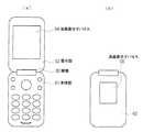
携帯電話では、いわゆる折り畳み型というタイプ(フリップタイプ)がある。図5に、この折り畳み型の携帯電話を模式的に示す。図5(a)は開いた状態を示し、図5(b)は折り畳んだ状態を示している。図示するように、このタイプの携帯電話は、複数のボタンが配設された本体部01と表示部02が、蝶番03により連結されており、本体部01に対して表示部02が開閉するようになっている。表示部02には、見開き側に配置されたメインの液晶表示パネル04と、折り畳み時に外側に配置されるサブの液晶表示パネル05が備えられている。つまり、表示部02では、メインの液晶表示パネル04とサブの液晶表示パネル05が背中合わせ状態に配置されている。そして、メインの液晶表示パネル04とサブの液晶表示パネル05を、それぞれ背面側から照明するために、メイン用の照明装置とサブ用の照明装置がそれぞれ設けられることがある。 There is a so-called folding type (flip type) in mobile phones. FIG. 5 schematically shows the foldable mobile phone. FIG. 5A shows an opened state, and FIG. 5B shows a folded state. As shown in the figure, in this type of mobile phone, a main body part 01 provided with a plurality of buttons and a
このように、メインとサブの液晶表示パネルを、それぞれ別々の照明装置により照明するようにした場合には、2つの照明装置が必要であるため、コストが増加すると共に部品点数が多くなり、重量増加や大型化してしまうという問題が生ずる。そこで、メインとサブの液晶表示デバイスを、1つの照明装置により照明するように構成して、薄型化を図った製品も主流になりつつある。このような製品では、メインの液晶表示パネルとサブの液晶表示パネルの間に1枚の導光板が配置されている。そして、発光ダイオードから導光板の側面に光を入射し、この入射した光を、導光板の上面側出光面(メイン液晶表示パネル側の面)と、導光板の下面側出光面(サブ液晶表示パネル側の面)から出射して、メインとサブの液晶表示パネルを照明している。このとき、大型のメイン液晶表示パネルに照射される光量を、小型のサブ液晶表示パネルに照射される光量よりも多くするため、導光板とサブ液晶表示パネルの間に、光の一部を透過して一部を反射する半透過反射シートを配置することもある(例えば、特許文献1を参照)。
メインとサブの液晶表示パネルを1つの照明装置を用いて照明する構成では、一枚の導光板から両面出光するため、バックライトの色としてはメインとサブが同じ色となる。通常、バックライトの色(即ち、照明装置から発生する光の色)は白色である。これは、カラー液晶表示パネルは、白色のバックライトで照明されることにより、最適なカラー表示ができるからである。 In a configuration in which the main and sub liquid crystal display panels are illuminated using a single lighting device, both sides emit light from a single light guide plate, so that the main and sub are the same color as the backlight. Usually, the color of the backlight (that is, the color of light generated from the lighting device) is white. This is because the color liquid crystal display panel can be optimally displayed by being illuminated with a white backlight.
しかしながら、メインの液晶表示パネルにはカラーの液晶表示パネルを用いるが、サブの液晶表示パネルにはモノクロの液晶表示パネルデバイスを使用いることもある。このような場合には、サブの液晶表示パネルは、当然ながら、モノクロ表示しかできず、表示画面に有彩色の表示はできない。携帯電話の本体部や表示部のケースはカラフルに着色しているにもかかわらず、サブの液晶表示パネルの表示がモノクロ表示となって有彩色の表示ができないのでは、商品として見劣りがすることがある。商品としての見栄え(デザイン性)をよくするには、モノクロの液晶表示パネルに、単色でもよいから有彩色の色が付いていることが有効である。 However, although a color liquid crystal display panel is used as the main liquid crystal display panel, a monochrome liquid crystal display panel device may be used as the sub liquid crystal display panel. In such a case, as a matter of course, the sub liquid crystal display panel can only perform monochrome display and cannot display chromatic colors on the display screen. Even though the case of the main body and display of the mobile phone is colorfully colored, if the display of the sub LCD panel is monochrome and cannot display chromatic colors, it will be inferior as a product. There is. In order to improve the appearance (designability) as a product, it is effective that the monochrome liquid crystal display panel has a chromatic color because it may be a single color.
そこで、本発明は、メインのカラー液晶表示パネルとサブのモノクロ液晶表示パネルを1つの照明装置で照明する電子機器において、モノクロタイプの液晶表示パネルにも色味をつけた表示ができるような両面表示装置を提供することを目的とする。 Therefore, the present invention provides a double-sided display that allows a monochrome type liquid crystal display panel to display a color in an electronic device that illuminates a main color liquid crystal display panel and a sub monochrome liquid crystal display panel with a single lighting device. An object is to provide a display device.
上記課題を解決するため、本発明の照明装置は、蛍光体を励起する波長を含んだ光を発生する光源と、光源で発生した光が入射面から入射されると、第一の出光面と第二の出光面から光を出射する導光板と、第一の出光面から出射した光の光路中に配置され、光源から発生した光と混合することにより白色光となる色成分の光を発生する蛍光体を含んだ白色化フィルムと、を備えることとした。 In order to solve the above-described problem, the illumination device of the present invention includes a light source that generates light including a wavelength that excites a phosphor, and a first light exit surface when light generated by the light source is incident from an incident surface. A light guide plate that emits light from the second light exit surface and a light component that is arranged in the optical path of the light emitted from the first light exit surface and mixes with the light generated from the light source to generate white light. And a whitening film containing a phosphor.
そして、蛍光体を励起する波長を含んだ光を発生するLED素子を、透明な封止樹脂で封止してなる光源を用い、この光源からの光が側面に入射されると、上面である第1の出光面と下面である第2の出光面から光を出射する、透明樹脂により板状に形成された導光板と、第1の出光面から出射した光が透過する位置に配置されるとともに発光ダイオードから発生した光と混合することにより透過して出て行く光を白色光とする色成分光の光を発生する蛍光体を備えた白色化フィルムとを有することを特徴とする。 Then, a light source formed by sealing a LED element that generates light including a wavelength that excites the phosphor with a transparent sealing resin is used, and when the light from this light source is incident on the side surface, it is the upper surface. A light guide plate formed in a plate shape with a transparent resin that emits light from the first light exit surface and the second light exit surface, which is the lower surface, and a position where the light emitted from the first light exit surface is transmitted. And a whitening film provided with a phosphor that generates light of color component light in which light that is transmitted through and emitted by mixing with light generated from a light emitting diode is white light.
また、蛍光体を励起することができる波長を含んだ光を発生する発光素子を、蛍光体が添加された透明な封止樹脂にて封止してなる光源と、透明樹脂により板状に形成されており、光源で発生した光が側面に入射されると、上面である第1の出光面と下面である第2の出光面から光を出射する導光板と、第1の出光面から出射した光が透過する位置に配置されると共に、発光ダイオードから発生した光と混合することにより透過して出て行く光を白色光とする色成分光の光を発生する蛍光体を備えた白色化フィルムとを有することを特徴とする。さらに、白色化フィルムは、蛍光体と透明ビーズとが分散混入した蛍光体分散層を有することとした。また、第2の出光面から出射した光が透過する位置に、顔料または蛍光体を分散した層を有するフィルタ、または特定色の色成分光をカットする特定色光カットフィルタを備えることとした。また、発光素子として、450〜470nmをピーク波長とする青色の光を発生するLED、または、近紫外光を発生するLEDを用いることとした。 In addition, a light-emitting element that generates light including a wavelength that can excite the phosphor is sealed with a transparent sealing resin to which the phosphor is added, and a plate is formed with the transparent resin. When the light generated by the light source is incident on the side surface, the light guide plate emits light from the first light output surface that is the upper surface and the second light output surface that is the lower surface, and the light is emitted from the first light output surface. Whitening with a phosphor that emits light of color component light that is arranged at a position where the transmitted light is transmitted and that mixes with the light generated from the light emitting diode to transmit and exit the light as white light And a film. Furthermore, the whitening film has a phosphor dispersion layer in which phosphors and transparent beads are dispersed and mixed. In addition, a filter having a layer in which a pigment or a phosphor is dispersed or a specific color light cut filter for cutting color component light of a specific color is provided at a position where light emitted from the second light output surface is transmitted. In addition, an LED that generates blue light having a peak wavelength of 450 to 470 nm or an LED that generates near-ultraviolet light is used as the light-emitting element.
また本発明の表示装置の構成は、メインのカラー液晶表示パネルとサブのモノクロ液晶表示パネルとが、間隔を空けて背中合わせ状態で配置され、メインの液晶表示パネルとサブの液晶表示パネルとの間に、第1の出光面がメインの液晶表示パネルの背面に対面すると共に第2の出光面がサブの液晶表示パネルの背面に対向する状態に両面照明装置を配置したことを特徴とする。このような両面表示装置を、折り畳み型の携帯電子機器の表示部に組み込むことができる。 In addition, the display device of the present invention is configured such that the main color liquid crystal display panel and the sub monochrome liquid crystal display panel are arranged back to back with a space therebetween, and the main liquid crystal display panel and the sub liquid crystal display panel are disposed between each other. In addition, the double-sided illumination device is arranged in a state where the first light exit surface faces the back surface of the main liquid crystal display panel and the second light exit surface faces the back surface of the sub liquid crystal display panel. Such a double-sided display device can be incorporated in a display portion of a foldable portable electronic device.
本発明によれば、単一種の光源と一枚の導光板を利用して複数色の照明光を得ることができる。そのため、単一種の光源と一枚の導光板を用いて、複数の表示部を異なる色で照明することが可能となる。 According to the present invention, illumination light of a plurality of colors can be obtained using a single type of light source and a single light guide plate. Therefore, it is possible to illuminate a plurality of display portions with different colors using a single type of light source and a single light guide plate.
本発明の照明装置は、蛍光体を励起する波長を含んだ光を発生する光源と、光源で発生した光が入射面から入射されると、第一の出光面と第二の出光面から光を出射する導光板と、第一の出光面から出射した光の光路中に配置され、光源から発生した光と混合することにより白色光となる色成分の光を発生する蛍光体を含んだ白色化フィルムと、を備えている。このような構成により、単一種の光源と一つの導光板を用いて、第一の出光面側を白色で照明し第二の出光面側を他の色で照明することができる。 The illuminating device of the present invention includes a light source that generates light including a wavelength that excites a phosphor, and light emitted from the light source is incident on the light incident surface from the first light exit surface and the second light exit surface. A white light source including a phosphor that emits light of a color component that is arranged in the optical path of light emitted from the first light exit surface and mixed with light generated from the light source to generate white light A film. With such a configuration, it is possible to illuminate the first light exit surface side in white and illuminate the second light exit surface side in another color using a single type of light source and one light guide plate.
このとき、光源は、蛍光体を励起する波長を含んだ光を発生する発光素子と、発光素子が発した光で励起して異なる波長成分の光を発する蛍光体が添加された透明樹脂を備えている。 At this time, the light source includes a light emitting element that generates light including a wavelength that excites the phosphor, and a transparent resin to which a phosphor that is excited by the light emitted from the light emitting element and emits light of different wavelength components is added. ing.
また、白色化フィルムが、蛍光体と透明ビーズとが分散混入された蛍光体分散層を有することとした。そのため、光源からの光の一部が必ず透明ビーズを透過することとなるので、光源の光の色のまま白色化フィルムを透過する率が高くなる。そのため、輝度が向上するとともに、この白色化フィルムを透過した光の色が確実に白色光となる。 In addition, the whitening film has a phosphor dispersion layer in which phosphors and transparent beads are dispersed and mixed. Therefore, a part of the light from the light source always passes through the transparent beads, so that the rate of transmission through the whitening film with the light color of the light source is increased. Therefore, the luminance is improved and the color of the light transmitted through the whitening film is surely white light.
次に、本発明の表示装置は、第一の表示部と、第二の表示部と、光源と、光源からの光を入射する入射面、第一の表示部を照明するための光が出射する第一の出光面、及び、第二の表示部を照明するための光が出射する第二の出光面を有する導光体と、を備え、第一の表示部と第一の出光面の間に、光源からの光の波長成分で励起して発光する光変換手段が設けられている。これにより、第一の表示部と第二の表示部を異なる色の光で照明することができる。すなわち、単一種の光源と一つの導光体を用いて、異なる色で複数の表示部を照明することができる。ここで、光源は、蛍光体を励起する波長を含んだ光を発生する発光素子と、発光素子が発した光で励起して異なる波長成分の光を発する蛍光体が添加された透明樹脂を備えている。 Next, the display device of the present invention includes a first display unit, a second display unit, a light source, an incident surface on which light from the light source is incident, and light for illuminating the first display unit. A first light exit surface, and a light guide having a second light exit surface from which light for illuminating the second display portion is emitted, and the first display portion and the first light exit surface In the meantime, there is provided light conversion means for emitting light by excitation with the wavelength component of light from the light source. Thereby, a 1st display part and a 2nd display part can be illuminated with the light of a different color. That is, a plurality of display units can be illuminated with different colors by using a single type of light source and a single light guide. Here, the light source includes a light emitting element that generates light including a wavelength for exciting the phosphor, and a transparent resin to which a phosphor that is excited by the light emitted from the light emitting element and emits light of different wavelength components is added. ing.
ここで、第一の表示部がカラーフィルタを有するカラー液晶表示素子に設けられ、第二の表示部がモノクロ表示を行なう液晶表示素子に設けられ、光変換手段が光源からの光を変換して白色光をカラー液晶表示素子に照射することができる構成とした。これにより、単一種の光源と一つの導光板を用いて、カラー液晶表示素子には色再現性の高い表示を実現するための照明を行なうとともに、モノクロ表示を行なう液晶表示パネルを着色光で照明することが可能になる。このとき、光変換手段は、光源からの光に励起して光源の光とは異なる色成分の光を発生する色蛍光体を備えており、光源からの光と、光源の光とは異なる色成分の光とを混合することにより白色光が作製される。 Here, the first display unit is provided in a color liquid crystal display element having a color filter, the second display unit is provided in a liquid crystal display element that performs monochrome display, and the light conversion means converts light from the light source. The color liquid crystal display element can be irradiated with white light. Thus, using a single type of light source and a single light guide plate, the color liquid crystal display element is illuminated to achieve a display with high color reproducibility, and the liquid crystal display panel for monochrome display is illuminated with colored light. It becomes possible to do. At this time, the light conversion means includes a color phosphor that is excited by the light from the light source to generate light having a color component different from that of the light source, and the light from the light source and the light from the light source have different colors. White light is produced by mixing the component light.
さらに、第二の出光面と第二の表示部の間に、顔料または蛍光体が分散された層を有するフィルタ、あるいは、光源が発光する光の色成分のうち特定色の色成分光をカットする特定色光カットフィルタを設けた。このような構成によれば、光源の発光色によらず、任意の色で第二の表示部を照明することが可能になる。例えば、カラーフィルタを用いた液晶表示装置に最適な白色光を得るために、光源と光変換手段がいくつかの組み合わせに限られることが考えられる。このような場合でも、第二の出光面と第二の表示部の間に前述のフィルタを用いることにより、光源の色とは異なる色の照明を第二の表示部に行うことができる。 Further, a filter having a layer in which a pigment or a phosphor is dispersed between the second light emitting surface and the second display unit, or a color component light of a specific color among the color components of light emitted from the light source is cut. A specific color light cut filter is provided. According to such a configuration, it is possible to illuminate the second display unit with an arbitrary color regardless of the emission color of the light source. For example, in order to obtain white light optimal for a liquid crystal display device using a color filter, it is conceivable that the light source and the light conversion means are limited to some combinations. Even in such a case, by using the above-described filter between the second light exit surface and the second display unit, illumination with a color different from the color of the light source can be performed on the second display unit.
以下に本発明の実施例を図面に基づき詳細に説明する。 Embodiments of the present invention will be described below in detail with reference to the drawings.
図1は、本実施例に係る両面表示装置を模式的に示す断面図である。図示するように、両面表示装置100のケース101には、一方にメインのカラー液晶表示パネル110が配置され、他方にサブのモノクロ液晶表示パネル111が配置されている。つまり、メインの液晶表示パネルとサブの液晶表示パネルが、間隔を空けて背中合わせ状態で配置されている。ここでは、メインの液晶表示パネルの面積に比べて、サブの液晶表示パネルの面積の方が狭くなっている。両液晶表示パネル110,111の間には、平面型の両面照明装置200が設けられている。 FIG. 1 is a cross-sectional view schematically showing a double-sided display device according to this embodiment. As shown, the
両面照明装置200の導光板210は、アクリルやポリカーボネートなどの透明樹脂で形成した矩形の板状部材であり、その上面(第1の出光面)211がメインの液晶表示パネル110の背面に対面し、その下面(第2の出光面)212がサブの液晶表示パネル111の背面に対面している。しかも、導光板210の上面及び下面の面積は、メインの液晶表示デバイス110の表示面と略同面積となっている。 The light guide plate 210 of the double-
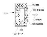
また、両面照明装置200にはLED素子をパッケージした光源220が用いられている。この光源220は導光板210の側面に対向して配置されている。図2にこの発光ダイオード220の詳細構造を示す。同示するように、本実施例による光源220は、ケース221内に配置されたLED素子222を、赤蛍光体223が添加されたシリコンやエポキシなどの透明な封止樹脂224にて封止して構成されている。なお、LED素子を駆動するために導線225が設けられている。 The double-
LED素子222は、InGaN系やGaN系の発光素子であり、青色の光(450〜470nmをピーク波長とする光)を発生する。赤蛍光体223は、赤色の光を発光する蛍光体であり、具体的には、CaS:EuやSrS:Eu等の硫化物にユーロピウムをドープしたものや、CaAlSiN3:Euのような窒化物系蛍光体や、有機系着色樹脂微粉末を採用する。このような材料を使用した赤蛍光体223は、LED素子222から青色の光が照射されると、この青色光により励起されて、赤色の光(蛍光)を発生する。このように、この光源220は、LED素子222が青色の光を発生し、赤蛍光体223が赤色の光を発生するため、光源220全体としては、紫色の紫色光L1を発生する。The
図1に戻り説明を続けると、光源220から発生した紫色光L1は、導光板210の側面に入射し、導光板210内を進行して出光面である上面211と下面212から出射される。導光板210の上面211と、メインの液晶表示パネル110との間には、蛍光フィルム(白色化フィルム)230が配置されている。更に、蛍光フィルム230とメインの液晶表示パネル110との間には、輝度を向上させるための2枚のプリズムシート241,242が配置されている。 Returning to FIG. 1, the violet light L1 generated from the
蛍光フィルム230は、導光板210の上面211から出射されてきた紫色光L11が透過することにより、フィルムを透過して出て行く光L2の色を白色とする機能を有する白色化フィルム(光波長変換フィルム)である。この蛍光フィルム(白色化フィルム)230の一具体例を図3に示す。図示するように、この蛍光フィルム230は、PET(ポリエチレンテレフタレート)フィルム231の上面に、アクリル等の透明樹脂(蛍光体分散層)234を印刷形成し、この透明樹脂234の上面にPETフィルム235を配置し、更に、PETフィルム235の上面に、透明ビーズ236を分散混入したアクリル等の透明樹脂237を印刷形成して構成されている。 The
しかも、透明樹脂(蛍光体分散層)234には、緑蛍光体232と透明ビーズ233を分散混入している。緑蛍光体232は、例えばSrGa2S4:EuやCaSrGa2S4:Euや有機系着色樹脂微粉末等であり、青色成分光が照射されると緑色の光を発生する。このため、蛍光フィルム230から出て行く光L2は、紫色光(青色成分光と赤色成分光よりなる光)L1−1と、緑蛍光体232から発生した緑色成分光とが混合した光であるため、白色光となる。In addition, green phosphor 232 and transparent beads 233 are dispersed and mixed in transparent resin (phosphor dispersion layer) 234. The green phosphor 232 is, for example, SrGa2 S4 : Eu, CaSrGa2 S4 : Eu, organic colored resin fine powder, or the like, and generates green light when irradiated with blue component light. For this reason, the light L <b> 2 exiting from the
なお紫色光L1−1のうち赤色成分光は、透明樹脂234中の緑蛍光体232に当たると、この緑蛍光体232に吸収されたり、反射されたりする。このため、仮に、透明樹脂234中に透明ビーズ233を分散混入させずに、緑蛍光体232のみを分散混入したとすると、透明樹脂234を透過してくる赤色成分光が大きく減少してしまい、蛍光フィルム230を透過してきた光が白色光にならない場合もある。本実施例では、透明樹脂234中に透明ビーズ233も分散混入しているため、赤色成分光の一部は、この透明ビーズ233の部分を通って通過するため、赤色成分光の透過率が向上する。このため、蛍光フィルム230を透過してきた光の中で赤色成分光の割合が少なくなることを防止でき、蛍光フィルム230を透過してきた光が白色光になると共に、この白色光L2の輝度が向上する。 In addition, when the red component light in the purple light L <b> 1-1 hits the green phosphor 232 in the transparent resin 234, the red component light is absorbed or reflected by the green phosphor 232. For this reason, if only the green phosphor 232 is dispersed and mixed without transparent beads 233 being dispersed and mixed in the transparent resin 234, the red component light transmitted through the transparent resin 234 is greatly reduced. The light transmitted through the
また、透明樹脂237には透明ビーズ236を分散混入しているため、白色光L2の拡散性及び分散性が向上して輝度の均一化を図ることができる。 Further, since the
なお、蛍光フィルム(白色化フィルム)としては、図3に示す構成のものに限らず、蛍光体を分散配置した蛍光体分散層を少なくとも有しており、この蛍光体で発した光の色成分光と、蛍光フィルムに入射してくる光の色成分光とが混合されることにより、当該蛍光フィルムを透過して出て行く光が白色光となるような構成となっていれば、他の構成部分はなくてもよい。 The fluorescent film (whitening film) is not limited to the one shown in FIG. 3, and has at least a phosphor dispersion layer in which phosphors are dispersed and color components of light emitted from the phosphors. If the light and the color component light of the light incident on the fluorescent film are mixed, the light that passes through the fluorescent film and goes out becomes white light. There may be no component.
再び図1に戻り説明を続けると、蛍光フィルム(白色化フィルム)230を透過してきた白色光L2は、2枚のプリズムシート241,242を透過することにより輝度が向上し、カラータイプの液晶表示パネルを背面から照明する。 Returning to FIG. 1 again and continuing the description, the white light L2 transmitted through the fluorescent film (whitening film) 230 is transmitted through the two
また、導光板210の下面212とサブの液晶表示パネル111との間には、半透過反射板250が配置されている。更に、この液晶表示パネルと半透過反射板250との間には、輝度を向上させるための2枚のプリズムシート243,244が配置されている。 A transflective plate 250 is disposed between the lower surface 212 of the light guide plate 210 and the sub liquid
半透過反射板250は、導光板210の下面から半透過反射膜250に入射した紫色光L1−2の一部を反射し、残りの一部を透過させる機能を有している。この半透過反射板250で反射した光は再び導光板210に入射して、その後に、上面211または下面212から光L1−1、L1−2として導光板210から再び出射する。このため、半透過反射板250は、表面積の大きいメイン側の輝度を向上するのに貢献する。一方、半透過反射板250を透過した紫色光L1−2は、2枚のプリズムシート243,244を透過することにより輝度が向上し、モノクロの液晶表示パネル111の背面を照明する。 The transflective plate 250 has a function of reflecting a part of the purple light L1-2 incident on the transflective film 250 from the lower surface of the light guide plate 210 and transmitting the remaining part. The light reflected by the transflective plate 250 enters the light guide plate 210 again, and then exits the light guide plate 210 again as light L1-1 and L1-2 from the upper surface 211 or the lower surface 212. For this reason, the transflective plate 250 contributes to improving the luminance on the main side having a large surface area. On the other hand, the violet light L1-2 transmitted through the transflective reflector 250 is transmitted through the two
上述したように、実施例1では、発光ダイオード220から出射した紫色光L1は、導光板210の側面に入射し、導光板210の上面211及び下面212から紫色光L1−1,L1−2として出射される。このうち、紫色光L1−1は、蛍光フィルム230を透過することにより緑色成分光が付加されて、白色光L2となり、この白色光L2がメインのカラータイプの液晶表示パネル110を背面側から照明する。カラータイプの液晶表示パネル110は白色光によりバックライト照明されることにより、最適な色を表示することができる。 As described above, in Example 1, the violet light L1 emitted from the
一方、紫色光L1−2は、半透過反射板250を透過して、サブのモノクロの液晶表示パネル111を背面側から照明する。このとき、サブの液晶表示パネル111は、モノクロ表示するものであるが、紫色光L1−2により紫色で照明されるため、サブ液晶表示パネルの表示面は面全体が紫色となり、デザイン性が向上して見栄えがよくなる。つまり、廉価で消費電力の少ないモノクロタイプの液晶表示パネル111を使用していても、サブ側においても単色ではあるが色付(有彩色の色付)の画面表示ができる。したがってモノクロタイプの液晶表示装置であっても、例えば、携帯電話の表示部100の外側の色とサブの液晶表示装置の発色を同じ色に合わせるなどのデザイン設計を行うことができる。このように、本発明の両面表示装置では、両面照明装置の一方の面から出射した白色光によりカラータイプの液晶表示パネルをバックライト照明することができるので、カラー液晶表示パネルの最適な色表示ができる。また両面照明装置の他方の面から出射した有彩色光によりモノクロタイプの液晶表示パネルをバックライト照明することができるので、モノクロ液晶表示パネルにおいて有彩色表示ができるようになった。 On the other hand, the violet light L1-2 passes through the transflective reflector 250 and illuminates the sub monochrome liquid
図1に示した実施例1において、更に、半透過反射板250とサブの液晶表示パネル111との間に、青色光カットフィルムを配置すれば、赤色の光によりサブの液晶表示パネル111をバックライト照明してこのサブ液晶表示パネルを赤色の画面表示とすることができる。また、半透過反射板250とサブの液晶表示パネル111との間に、赤色光カットフィルムを配置すれば、青色の光でサブの液晶表示パネル111をバックライト照明することとなり、サブの表示パネルを青色の画面表示とすることができる。 In the first embodiment shown in FIG. 1, if a blue light cut film is further disposed between the transflective plate 250 and the sub liquid
また、半透過反射板250とサブの液晶表示パネル111との間に、蛍光体を分散した層を有するフィルムや、顔料を分散した層を有するフィルムを配置することにより、サブの表示パネルを任意の色(有彩色)の光によりバックライト照明して、このサブ表示を任意の色の画面表示とすることができる。 Further, by arranging a film having a phosphor dispersed layer or a film having a pigment dispersed layer between the transflective plate 250 and the sub liquid
実施例1では、LED素子222が青色を発光し、封止樹脂224に添加した赤蛍光体223により赤色を発光し、蛍光フィルム(白色化フィルム)230により緑色を発光することにより、メインの液晶パネル110を照明する光L2を白色としているが、液晶パネルを照明する光を白色にするには、上述した例に限るものではなく、各種の組合せにより、白色光を得ることができる。ここで、白色光を得るためる各種の組合せ例を示す。 In the first embodiment, the
(1)第1の例では、発光素子として青色を発光する発光素子を使用し、封止樹脂には蛍光体を添加せず、白色化フィルムには黄色を発光する蛍光体を分散混入する。これによりメインの液晶表示パネルを白色光により照明することができる。この場合には、サブの液晶表示パネルを青色光により照明することとなる。もちろん、サブの液晶表示パネルの手前に、各種の色付フィルタ(顔料または蛍光体を分散した層を有するフィルタ)や特定色光カットフィルタを備えることにより、色付フィルタにより付加した色の光や、特定色光カットフィルタにより特定の色成分光をカットした色により、サブの液晶表示パネルを照明することができる。 (1) In the first example, a light emitting element that emits blue light is used as the light emitting element, and no phosphor is added to the sealing resin, and a phosphor that emits yellow light is dispersed and mixed in the whitened film. Thereby, the main liquid crystal display panel can be illuminated with white light. In this case, the sub liquid crystal display panel is illuminated with blue light. Of course, in front of the sub liquid crystal display panel, by providing various colored filters (filters having a layer in which pigments or phosphors are dispersed) and specific color light cut filters, the light of the color added by the colored filters, The sub liquid crystal display panel can be illuminated with a color obtained by cutting the specific color component light with the specific color light cut filter.
(2)第2の例では、発光素子として青色を発光する発光素子を使用し、封止樹脂には蛍光体を添加せず、白色化フィルムには赤色を発光する蛍光体と緑色を発光する蛍光体を分散混入する。これによりメインの液晶表示パネルを白色光により照明することができる。この場合には、サブの液晶表示パネルを青色光により照明することとなる。もちろん、サブの液晶表示パネルの手前に、各種の色付フィルタや特定色光カットフィルタを備えることにより、色付フィルタにより付加した色の光や、特定色光カットフィルタにより特定の色成分光をカットした色により、サブの液晶表示パネルを照明することができる。 (2) In the second example, a light-emitting element that emits blue light is used as the light-emitting element, no phosphor is added to the sealing resin, and the whitened film emits red and green phosphors. Disperse and mix phosphors. Thereby, the main liquid crystal display panel can be illuminated with white light. In this case, the sub liquid crystal display panel is illuminated with blue light. Of course, by providing various colored filters and specific color light cut filters in front of the sub liquid crystal display panel, the color light added by the colored filters and the specific color component light are cut by the specific color light cut filters. The sub liquid crystal display panel can be illuminated by the color.
(3)第3の例では、発光素子として青色を発光する発光素子を使用し、封止樹脂に緑色を発光する蛍光体を添加し、白色化フィルムに赤色を発光する蛍光体を分散混入する。これによりメインの液晶表示パネルを白色光により照明することができる。この場合には、サブの液晶表示パネルを青緑色光により照明することができる。もちろん、サブの液晶表示パネルの手前に、特定色光カットフィルタを備えることにより、特定色光カットフィルタにより特定の色成分光をカットした色により、サブの液晶表示パネルを照明することができる。例えば、青カットフィルムを使用すればサブの液晶表示パネルを緑色照明することができ、緑カットフィルムを使用すればサブの液晶表示デバイスを青色照明することができる。 (3) In the third example, a blue light emitting element is used as the light emitting element, a phosphor emitting green light is added to the sealing resin, and a phosphor emitting red light is dispersed and mixed in the whitened film. . Thereby, the main liquid crystal display panel can be illuminated with white light. In this case, the sub liquid crystal display panel can be illuminated with blue-green light. Of course, by providing the specific color light cut filter in front of the sub liquid crystal display panel, the sub liquid crystal display panel can be illuminated with a color obtained by cutting the specific color component light by the specific color light cut filter. For example, if a blue cut film is used, the sub liquid crystal display panel can be illuminated in green, and if a green cut film is used, the sub liquid crystal display device can be illuminated in blue.
上述した(1)〜(3)の例は一例であり、各種の組合せとすることができる。また、発光素子としては青色を発光する発光素子のみならず、近紫外光を発生する発光素子を使用することもできる。要は、発光素子から発生する光が、蛍光体を励起することができる波長の光であればよい。 The example of (1)-(3) mentioned above is an example, and it can be set as various combinations. As the light emitting element, not only a light emitting element that emits blue light but also a light emitting element that generates near-ultraviolet light can be used. In short, the light generated from the light emitting element may be light having a wavelength capable of exciting the phosphor.
発光素子(LED素子)と封止材料に添加する蛍光体との組合せ例を、以下の表1に示す。このような組合せを用いることにより、光源全体として各種の色の光を発生することができる。 Table 1 below shows examples of combinations of light emitting elements (LED elements) and phosphors added to the sealing material. By using such a combination, light of various colors can be generated as the entire light source.

本発明の両面照明装置及び両面表示装置は、例えば、折り畳み式の携帯電話に用いることができる。すなわち、メインのカラー液晶表示パネルと、サブのモノクロの液晶表示パネルが背中合わせに配置されている、携帯情報端末などの各種の電子機器の表示装置として適用することができる。 The double-sided illumination device and the double-sided display device of the present invention can be used for, for example, a folding cellular phone. That is, it can be applied as a display device of various electronic devices such as a portable information terminal in which a main color liquid crystal display panel and a sub monochrome liquid crystal display panel are arranged back to back.
100 両面表示装置
101 ケース
110,111 液晶表示パネル
200 両面照明装置
210 導光板
211 上面
212 下面
220 光源
221 ケース
222 LED素子
223 赤蛍光体
224 封止樹脂
230 蛍光フィルム(白色化フィルム)
241,242,243,244 プリズムシート
250 半透過反射板DESCRIPTION OF
241, 242, 243, 244 Prism sheet 250 Transflective plate
Claims (10)
Translated fromJapanese第二の表示部と、
光源と、
前記光源からの光を入射する入射面、前記第一の表示部を照明するための光が出射する第一の出光面、及び、前記第二の表示部を照明するための光が出射する第二の出光面を有する導光体と、
前記第一の表示部と前記第一の出光面の間に設けられた、前記光源からの光の波長成分で励起して前記光源の光とは異なる第一の波長成分の光を発光する第一の蛍光体と、第一の透明ビーズとが分散された蛍光体分散層と、
前記第一の表示部と前記蛍光体分散層の間に設けられた、第二の透明ビーズが分散された透明樹脂層と、を備え、
前記第一の表示部と前記第二の表示部が異なる色の光で照射されることを特徴とする表示装置。A first display;
A second display,
A light source;
An incident surface on which light from the light source is incident, a first light exit surface from which light for illuminating the first display unit is emitted, and a light from which light for illuminating the second display unit is emitted. A light guide having two light exit surfaces;
A first light source, which is provided between the first display unit and the first light exit surface, emitslight having a first wavelength component different from that of the light source by being excited by the wavelength component of the light from the lightsource. one phosphor, aphosphor dispersion layer and thefirst transparent beads are dispersed,
A transparent resin layer provided between the first display unit and thephosphor dispersion layer , in whichsecond transparent beads are dispersed;
The display device, wherein the first display unit and the second display unit are irradiated with light of different colors.
前記光源で発生した光が入射面から入射されると、第一の出光面と第二の出光面から光を出射する導光板と、
前記第一の出光面から出射した光の光路中に配置され、前記光源からの光の波長成分で励起して前記光源の光とは異なる第一の波長成分の光を発光する第一の蛍光体と、第一の透明ビーズとが分散された蛍光体分散層と、
前記蛍光体分散層の外方に設けられた、第二の透明ビーズが分散された透明樹脂層と、を備え、
前記第一の出光面と前記第二の出光面から観察する光の色が異なることを特徴とする照明装置。A light source;
When the light generated by the light source is incident from the incident surface, a light guide plate that emits light from the first light exit surface and the second light exit surface;
The first fluorescence arranged in the optical path of the light emitted from the first light exit surface and excited by the wavelength component of the light from the light source toemit light having a first wavelength component different from the light of the light source And a phosphor dispersion layer in which the first transparent beads are dispersed,
A transparent resin layer in which second transparent beads are dispersed, provided outside the phosphor dispersion layer ,
The illumination device, wherein thecolor of lightobserved from the first lightexit surface and the second lightexit surfaceis different .
前記第一の蛍光体が緑色蛍光体であり、蛍光体分散層がPETフィルムで挟まれて蛍光フィルムを構成することを特徴とする請求項9に記載の照明装置。The light source has a configuration in which a blue LED is sealed with a resin to which a red phosphor that emits red component light when excited by blue light is added,
The lighting device according to claim 9,wherein the first phosphor is a green phosphor, and the phosphor dispersion layer is sandwiched between PET films to form a phosphor film .
Priority Applications (2)
| Application Number | Priority Date | Filing Date | Title |
|---|---|---|---|
| JP2006217124AJP4751269B2 (en) | 2006-08-09 | 2006-08-09 | Illumination device, display device including the same, and portable electronic device |
| US11/827,069US7597470B2 (en) | 2006-08-09 | 2007-07-10 | Illuminating device, and display device and portable electronic device having the same |
Applications Claiming Priority (1)
| Application Number | Priority Date | Filing Date | Title |
|---|---|---|---|
| JP2006217124AJP4751269B2 (en) | 2006-08-09 | 2006-08-09 | Illumination device, display device including the same, and portable electronic device |
Publications (3)
| Publication Number | Publication Date |
|---|---|
| JP2008041550A JP2008041550A (en) | 2008-02-21 |
| JP2008041550A5 JP2008041550A5 (en) | 2009-07-23 |
| JP4751269B2true JP4751269B2 (en) | 2011-08-17 |
Family
ID=39050562
Family Applications (1)
| Application Number | Title | Priority Date | Filing Date |
|---|---|---|---|
| JP2006217124AExpired - Fee RelatedJP4751269B2 (en) | 2006-08-09 | 2006-08-09 | Illumination device, display device including the same, and portable electronic device |
Country Status (2)
| Country | Link |
|---|---|
| US (1) | US7597470B2 (en) |
| JP (1) | JP4751269B2 (en) |
Families Citing this family (38)
| Publication number | Priority date | Publication date | Assignee | Title |
|---|---|---|---|---|
| US8718437B2 (en)* | 2006-03-07 | 2014-05-06 | Qd Vision, Inc. | Compositions, optical component, system including an optical component, devices, and other products |
| US8215815B2 (en) | 2005-06-07 | 2012-07-10 | Oree, Inc. | Illumination apparatus and methods of forming the same |
| WO2006131924A2 (en) | 2005-06-07 | 2006-12-14 | Oree, Advanced Illumination Solutions Inc. | Illumination apparatus |
| US8272758B2 (en) | 2005-06-07 | 2012-09-25 | Oree, Inc. | Illumination apparatus and methods of forming the same |
| US8849087B2 (en)* | 2006-03-07 | 2014-09-30 | Qd Vision, Inc. | Compositions, optical component, system including an optical component, devices, and other products |
| US9874674B2 (en) | 2006-03-07 | 2018-01-23 | Samsung Electronics Co., Ltd. | Compositions, optical component, system including an optical component, devices, and other products |
| US8836212B2 (en)* | 2007-01-11 | 2014-09-16 | Qd Vision, Inc. | Light emissive printed article printed with quantum dot ink |
| KR101730164B1 (en)* | 2007-07-18 | 2017-04-25 | 삼성전자주식회사 | Quantum dot-based light sheets useful for solid-state lighting |
| US7907804B2 (en) | 2007-12-19 | 2011-03-15 | Oree, Inc. | Elimination of stitch artifacts in a planar illumination area |
| US8182128B2 (en)* | 2007-12-19 | 2012-05-22 | Oree, Inc. | Planar white illumination apparatus |
| US8651723B2 (en)* | 2008-02-21 | 2014-02-18 | Koninklijke Philips N.V. | LED light source with a luminescent layer |
| WO2009137053A1 (en) | 2008-05-06 | 2009-11-12 | Qd Vision, Inc. | Optical components, systems including an optical component, and devices |
| US9207385B2 (en) | 2008-05-06 | 2015-12-08 | Qd Vision, Inc. | Lighting systems and devices including same |
| WO2009151515A1 (en) | 2008-05-06 | 2009-12-17 | Qd Vision, Inc. | Solid state lighting devices including quantum confined semiconductor nanoparticles |
| US8297786B2 (en) | 2008-07-10 | 2012-10-30 | Oree, Inc. | Slim waveguide coupling apparatus and method |
| US8301002B2 (en) | 2008-07-10 | 2012-10-30 | Oree, Inc. | Slim waveguide coupling apparatus and method |
| US8624527B1 (en) | 2009-03-27 | 2014-01-07 | Oree, Inc. | Independently controllable illumination device |
| KR101753740B1 (en) | 2009-04-28 | 2017-07-04 | 삼성전자주식회사 | Optical materials, optical components, and methods |
| US20100320904A1 (en) | 2009-05-13 | 2010-12-23 | Oree Inc. | LED-Based Replacement Lamps for Incandescent Fixtures |
| WO2010150516A1 (en)* | 2009-06-22 | 2010-12-29 | パナソニック株式会社 | Surface light source and liquid crystal display device |
| WO2010150202A2 (en) | 2009-06-24 | 2010-12-29 | Oree, Advanced Illumination Solutions Inc. | Illumination apparatus with high conversion efficiency and methods of forming the same |
| CN102598313B (en) | 2009-08-14 | 2016-03-23 | Qd视光有限公司 | Light emitting device, optical element for light emitting device, and method |
| CN102374497A (en)* | 2010-08-17 | 2012-03-14 | 海洋王照明科技股份有限公司 | Light guide plate and LED (light emitting diode) light source assembly |
| US8651725B2 (en)* | 2010-09-30 | 2014-02-18 | Global Lighting Technology Inc. | Backlight module |
| TWI428530B (en)* | 2011-01-18 | 2014-03-01 | Young Lighting Technology Corp | Illuminating module |
| JP6083931B2 (en)* | 2011-05-27 | 2017-02-22 | エルジー イノテック カンパニー リミテッド | Lighting module |
| US8591072B2 (en) | 2011-11-16 | 2013-11-26 | Oree, Inc. | Illumination apparatus confining light by total internal reflection and methods of forming the same |
| TW201339707A (en)* | 2012-03-19 | 2013-10-01 | Chunghwa Picture Tubes Ltd | Backlight module |
| WO2014006501A1 (en) | 2012-07-03 | 2014-01-09 | Yosi Shani | Planar remote phosphor illumination apparatus |
| US20140218968A1 (en)* | 2013-02-05 | 2014-08-07 | National Central University | Planar lighting device |
| US10490711B2 (en) | 2014-10-07 | 2019-11-26 | Nichia Corporation | Light emitting device |
| JP6657735B2 (en)* | 2014-10-07 | 2020-03-04 | 日亜化学工業株式会社 | Light emitting device |
| WO2016122284A1 (en)* | 2015-01-31 | 2016-08-04 | 주식회사 엘지화학 | Back-light unit and display apparatus comprising same |
| CN108398872B (en)* | 2017-02-06 | 2019-08-27 | 京东方科技集团股份有限公司 | A holographic display, its display method, and display device |
| CN107132693A (en)* | 2017-05-10 | 2017-09-05 | 南通天鸿镭射科技有限公司 | A kind of quantum dot fluorescence screen |
| CN108490684A (en)* | 2018-03-15 | 2018-09-04 | 京东方科技集团股份有限公司 | Backlight module and display device |
| JP2022124712A (en)* | 2021-02-16 | 2022-08-26 | 東洋電装株式会社 | lighting equipment |
| US12429187B1 (en)* | 2024-05-14 | 2025-09-30 | Hyundai Mobis Co., Ltd. | Optical module and vehicle having the same |
Family Cites Families (8)
| Publication number | Priority date | Publication date | Assignee | Title |
|---|---|---|---|---|
| JP4026374B2 (en)* | 2002-02-15 | 2007-12-26 | セイコーエプソン株式会社 | Liquid crystal device, lighting device and electronic apparatus |
| JP4048844B2 (en)* | 2002-06-17 | 2008-02-20 | カシオ計算機株式会社 | Surface light source and display device using the same |
| JP3719433B2 (en)* | 2002-10-30 | 2005-11-24 | セイコーエプソン株式会社 | Display device and electronic device |
| EP1627177A1 (en)* | 2003-05-09 | 2006-02-22 | Philips Intellectual Property & Standards GmbH | Uv light source coated with nano-particles of phosphor |
| JP2006012506A (en)* | 2004-06-24 | 2006-01-12 | Citizen Watch Co Ltd | Lighting system and display device using it |
| KR100735148B1 (en)* | 2004-11-22 | 2007-07-03 | (주)케이디티 | Backlight unit by phosphorescent diffusion sheet |
| JP2007053170A (en)* | 2005-08-16 | 2007-03-01 | Toshiba Corp | Light emitting device |
| US20080219025A1 (en)* | 2007-03-07 | 2008-09-11 | Spitzer Mark B | Bi-directional backlight assembly |
- 2006
- 2006-08-09JPJP2006217124Apatent/JP4751269B2/ennot_activeExpired - Fee Related
- 2007
- 2007-07-10USUS11/827,069patent/US7597470B2/enactiveActive
Also Published As
| Publication number | Publication date |
|---|---|
| US20080037282A1 (en) | 2008-02-14 |
| US7597470B2 (en) | 2009-10-06 |
| JP2008041550A (en) | 2008-02-21 |
Similar Documents
| Publication | Publication Date | Title |
|---|---|---|
| JP4751269B2 (en) | Illumination device, display device including the same, and portable electronic device | |
| JP4469307B2 (en) | Display device | |
| JP5764434B2 (en) | Illumination device and color display device including the same | |
| CN107407465B (en) | Lighting device, display device and television receiver | |
| JP4898332B2 (en) | Display device | |
| CN100559236C (en) | Light source, display, terminal device, light source unit and method for driving light source device | |
| US20080284316A1 (en) | Illuminating device, display device and optical film | |
| JP4976196B2 (en) | Display device and lighting device | |
| JP2010092705A (en) | Illuminating device and display device using this | |
| US6871972B2 (en) | Light module for LCD panel | |
| US6894750B2 (en) | Transflective color liquid crystal display with internal rear polarizer | |
| US20030042845A1 (en) | Light source with cascading dyes and BEF | |
| JP4388360B2 (en) | Illumination device and liquid crystal display device | |
| JP2011119131A (en) | Lighting device and display device with the same | |
| US20150369989A1 (en) | Backlight module and display device | |
| JP2008108523A (en) | Lighting system, and display device equipped with it | |
| WO2013144964A1 (en) | Illumination system and method for backlighting | |
| US6871973B2 (en) | Light module for LCD panel | |
| JP2009224245A (en) | Light emitting fixture and liquid crystal display device | |
| CN100474059C (en) | Liquid crystal display with enhanced color | |
| JP2004085822A (en) | Display method and display apparatus | |
| WO2021249307A1 (en) | Edge-lit backlight module, display panel and display device | |
| TWI424229B (en) | Display with backlight | |
| JP4803632B2 (en) | Liquid crystal display | |
| JP2009266776A (en) | Liquid crystal display device, and reflective plate unit for backlight |
Legal Events
| Date | Code | Title | Description |
|---|---|---|---|
| A521 | Written amendment | Free format text:JAPANESE INTERMEDIATE CODE: A523 Effective date:20090604 | |
| A621 | Written request for application examination | Free format text:JAPANESE INTERMEDIATE CODE: A621 Effective date:20090604 | |
| RD01 | Notification of change of attorney | Free format text:JAPANESE INTERMEDIATE CODE: A7421 Effective date:20091105 | |
| RD01 | Notification of change of attorney | Free format text:JAPANESE INTERMEDIATE CODE: A7421 Effective date:20091113 | |
| A977 | Report on retrieval | Free format text:JAPANESE INTERMEDIATE CODE: A971007 Effective date:20101118 | |
| A131 | Notification of reasons for refusal | Free format text:JAPANESE INTERMEDIATE CODE: A131 Effective date:20101130 | |
| A521 | Written amendment | Free format text:JAPANESE INTERMEDIATE CODE: A523 Effective date:20110126 | |
| TRDD | Decision of grant or rejection written | ||
| A01 | Written decision to grant a patent or to grant a registration (utility model) | Free format text:JAPANESE INTERMEDIATE CODE: A01 Effective date:20110517 | |
| A01 | Written decision to grant a patent or to grant a registration (utility model) | Free format text:JAPANESE INTERMEDIATE CODE: A01 | |
| A61 | First payment of annual fees (during grant procedure) | Free format text:JAPANESE INTERMEDIATE CODE: A61 Effective date:20110520 | |
| R150 | Certificate of patent or registration of utility model | Ref document number:4751269 Country of ref document:JP Free format text:JAPANESE INTERMEDIATE CODE: R150 Free format text:JAPANESE INTERMEDIATE CODE: R150 | |
| FPAY | Renewal fee payment (event date is renewal date of database) | Free format text:PAYMENT UNTIL: 20140527 Year of fee payment:3 | |
| R250 | Receipt of annual fees | Free format text:JAPANESE INTERMEDIATE CODE: R250 | |
| R250 | Receipt of annual fees | Free format text:JAPANESE INTERMEDIATE CODE: R250 | |
| R250 | Receipt of annual fees | Free format text:JAPANESE INTERMEDIATE CODE: R250 | |
| LAPS | Cancellation because of no payment of annual fees |