JP4750175B2 - Stereo optical system, and stereo measurement optical apparatus, stereo measurement apparatus, and stereo observation apparatus using the same - Google Patents
Stereo optical system, and stereo measurement optical apparatus, stereo measurement apparatus, and stereo observation apparatus using the sameDownload PDFInfo
- Publication number
- JP4750175B2 JP4750175B2JP2008305114AJP2008305114AJP4750175B2JP 4750175 B2JP4750175 B2JP 4750175B2JP 2008305114 AJP2008305114 AJP 2008305114AJP 2008305114 AJP2008305114 AJP 2008305114AJP 4750175 B2JP4750175 B2JP 4750175B2
- Authority
- JP
- Japan
- Prior art keywords
- optical system
- optical
- stereo
- optical path
- path switching
- Prior art date
- Legal status (The legal status is an assumption and is not a legal conclusion. Google has not performed a legal analysis and makes no representation as to the accuracy of the status listed.)
- Active
Links
Images


Classifications
- G—PHYSICS
- G02—OPTICS
- G02B—OPTICAL ELEMENTS, SYSTEMS OR APPARATUS
- G02B23/00—Telescopes, e.g. binoculars; Periscopes; Instruments for viewing the inside of hollow bodies; Viewfinders; Optical aiming or sighting devices
- G02B23/24—Instruments or systems for viewing the inside of hollow bodies, e.g. fibrescopes
- G02B23/2407—Optical details
- G02B23/2415—Stereoscopic endoscopes
- A—HUMAN NECESSITIES
- A61—MEDICAL OR VETERINARY SCIENCE; HYGIENE
- A61B—DIAGNOSIS; SURGERY; IDENTIFICATION
- A61B1/00—Instruments for performing medical examinations of the interior of cavities or tubes of the body by visual or photographical inspection, e.g. endoscopes; Illuminating arrangements therefor
- A61B1/00163—Optical arrangements
- A61B1/00193—Optical arrangements adapted for stereoscopic vision
- A—HUMAN NECESSITIES
- A61—MEDICAL OR VETERINARY SCIENCE; HYGIENE
- A61B—DIAGNOSIS; SURGERY; IDENTIFICATION
- A61B1/00—Instruments for performing medical examinations of the interior of cavities or tubes of the body by visual or photographical inspection, e.g. endoscopes; Illuminating arrangements therefor
- A61B1/04—Instruments for performing medical examinations of the interior of cavities or tubes of the body by visual or photographical inspection, e.g. endoscopes; Illuminating arrangements therefor combined with photographic or television appliances
- A61B1/042—Instruments for performing medical examinations of the interior of cavities or tubes of the body by visual or photographical inspection, e.g. endoscopes; Illuminating arrangements therefor combined with photographic or television appliances characterised by a proximal camera, e.g. a CCD camera
Landscapes
- Health & Medical Sciences (AREA)
- Life Sciences & Earth Sciences (AREA)
- Surgery (AREA)
- Physics & Mathematics (AREA)
- Optics & Photonics (AREA)
- General Health & Medical Sciences (AREA)
- Radiology & Medical Imaging (AREA)
- Public Health (AREA)
- Molecular Biology (AREA)
- Biophysics (AREA)
- Nuclear Medicine, Radiotherapy & Molecular Imaging (AREA)
- Pathology (AREA)
- Engineering & Computer Science (AREA)
- Biomedical Technology (AREA)
- Heart & Thoracic Surgery (AREA)
- Medical Informatics (AREA)
- Veterinary Medicine (AREA)
- Animal Behavior & Ethology (AREA)
- Astronomy & Astrophysics (AREA)
- General Physics & Mathematics (AREA)
- Endoscopes (AREA)
- Instruments For Viewing The Inside Of Hollow Bodies (AREA)
- Lenses (AREA)
- Testing, Inspecting, Measuring Of Stereoscopic Televisions And Televisions (AREA)
Description
Translated fromJapanese本発明は、ステレオ光学系、並びにそれを用いたステレオ計測用光学装置、ステレオ計測装置及びステレオ観察装置に関する。 The present invention relates to a stereo optical system, and a stereo measurement optical device, a stereo measurement device, and a stereo observation device using the stereo optical system.
機械内部の損傷や欠損、患部等の計測対象を定量的に把握したいという要望が高まっている。そのような、損傷や欠損、患部等の計測対象を定量的に計測する技術として、同一箇所を視差のある二方向から撮像し、撮像した画像間の相関演算により各画像上での対応する計測点のズレ量を求め、求めたズレ量から三角測量の原理で物体の大きさや深さ等を計測するステレオ計測が知られている。 There is an increasing demand for quantitatively grasping measurement objects such as damage and defects inside the machine and affected areas. As a technique for quantitatively measuring measurement targets such as damage, defects, and affected parts, the same location is imaged from two directions with parallax, and the corresponding measurement on each image is performed by correlation calculation between the captured images. Stereo measurement is known in which the amount of deviation of a point is obtained, and the size and depth of an object are measured from the obtained amount of deviation by the principle of triangulation.
従来、視差のある像を撮像する光学系としては、例えば、次の特許文献1〜5に記載の光学系が提案されている。
特許文献1に記載の光学系は、内視鏡挿入部先端に設けられている。そして、例えば、図14に示すように、並列配置された負レンズ51L,51Rと、軸対称な正レンズ群52とで構成された対物光学系53と、並列配置された2つの撮像素子54L,54Rを有している。図14中、52R,52Lは、正レンズ群52内に設けられた絞り開口部である。そして、対物光学系53を介して2光路を形成し、視差のある光学像55L,55Rを2つの撮像素子54L,54Rの撮像面に結像するようになっている。 The optical system described in
また、特許文献2に記載の光学系は、計測又は立体視を行うための対物光学系を含む内視鏡装置に用いられている。そして、例えば、図15に示すように、2組のレンズ60L,60Rを並列配置した負パワーの第1ユニット60と、正パワーの第2ユニット61と、正パワーの第3ユニット62と、一つの撮像素子63aを含む撮像ユニット63とで構成されている。そして、第1ユニット60〜第3ユニット62を介して視差を持つ2画像を一つの撮像素子63a上に形成するようになっている。 The optical system described in
また、特許文献3に記載の光学系は、内視鏡挿入部先端に設けられている。そして、例えば、図16に示すように、一対の負レンズ71L,71Rと、一対の正レンズ72L,72Rと、一つの正レンズ群73で構成された対物光学系74と、一つの撮像素子75を有している。そして、対物光学系74を介して視差を持つ2画像を一つの撮像素子75上に形成するようになっている。 Further, the optical system described in
また、特許文献4に記載の光学系は、立体視硬性内視鏡に用いられている。そして、例えば、図17(a)に示すように、一つの光軸を有し且つ少なくとも一つのリレーレンズを含むリレーレンズ系(図示省略)による最終像Inの位置から後方へ順に、瞳位置近傍に配置された瞳分割手段81と一つの結像光学系82と、一つの撮像素子83とで構成されている。瞳分割手段81は、例えば、図17(b)に示すような開口部81aを設けた回転円板や、図17(c)に示すような開口部81a(81b)の位置が変化する液晶シャッタが用いられる。そして、瞳分割手段81を介して時分割で瞳分割された2つの像を、撮像素子83で撮像するようになっている。 Moreover, the optical system described in
また、特許文献5に記載の光学系は、立体視内視鏡に用いられている。そして、例えば、図18(a)に示すように、対物光学系91と、リレーレンズ系92a,92b,92cと、瞳分割結像手段93と、内視鏡の把持部内に設けられた撮像素子94R,94Lとを有している。対物光学系91は、互いの光軸間隔が所定距離d離れて平行配置された一対の前群光学系911R,911Lと、一つの光軸上に配置された後群光学系912とで構成されており、視差のある2つの像95R,95Lを空間的にほぼ一致した位置に結像する。リレーレンズ系92a,92b,92cは、互いに同じ光軸となるように、直列に配置され、像95R,95Lを等倍にリレーする。瞳分割結像手段93は、瞳結像レンズ系93aと、ミラー部93bR,93bLと、結像レンズ系93cR,93cLとで構成されている。瞳結像レンズ系93aは、リレーレンズ系92a,92b,92cによって伝送された対物光学系91の2つの瞳を空間的に離れた位置に結像させる。ミラー部93bR,93bLは、2つの瞳の光束を互いに離れるように平行移動させる。結像レンズ系93cR,93cLは、それぞれ、像96R,96Lを撮像素子94R,94Lに結像させるようになっている。Moreover, the optical system described in
また、特許文献5に記載の光学系は、例えば、図18(b)に示すように、リレーレンズ系92cの像側に、リレーレンズ系92cと同じ光軸上に配置された、瞳結像レンズ系93a’と結像レンズ系93c’とでさらに1回リレーするようになっている。リレーされた像96R,96Lは略同じ位置に結像され、これを一つの撮像素子94’で撮像するようになっている。瞳結像レンズ系93a’と結像レンズ系93c’との間には、シャッタ97が配置され、撮像素子94’に2つの像が同時に結像しないように交互に光束を遮断するようになっている。 In addition, the optical system described in
しかし、特許文献1に記載の光学系のように、内視鏡挿入部先端に、2つの撮像素子を並列配置して視差のある左右の像を撮像する構成の場合、夫々の撮像素子を小さくせざるを得ない。
これは、次のような理由による。即ち、2つの撮像素子をそのままの大きさで並列配置すべく内視鏡挿入部先端の径を大きくすると、径の細い管内や隙間の狭い内部に対しては内視鏡を挿入できず計測に支障が生じる。また、径の大きさに制限のある内視鏡挿入部先端に通常サイズの撮像素子を並列配置するスペースをとることが難しい。
しかし、撮像素子を小さくすると、視差のある夫々の像の撮像面積が小さくなるため、夫々の像に対する解像度が悪くなる。However, as in the case of the optical system described in
This is due to the following reason. That is, if the diameter of the endoscope insertion section tip is increased so that the two image sensors are arranged in parallel with each other as they are, the endoscope cannot be inserted into a thin tube or inside a narrow gap for measurement. It will cause trouble. In addition, it is difficult to take a space for arranging a normal-size image sensor in parallel at the distal end of the endoscope insertion portion with a limited diameter.
However, if the imaging device is made smaller, the imaging area of each image with parallax becomes smaller, so the resolution for each image becomes worse.
また、特許文献2や特許文献3に記載の光学系のように、1つの撮像素子に視差のある左右の像を結像するために撮像領域を2つに分割する構成も、視差のある夫々の像の撮像面積が小さくなるため、夫々の像に対する解像度が悪くなる。 In addition, as in the optical systems described in
これに対し、特許文献4に記載の光学系のように、瞳分割手段を介して時分割で瞳分割された2つの像を一つの撮像素子に撮像すれば、夫々の像の撮像素子における撮像面積を大きくとることができる。
しかし、特許文献4に記載の光学系のように、瞳分割手段を介して瞳を分割する構成では、視差を大きくとることができず、特に遠点では視差が小さくなり過ぎてステレオ計測が難しい。視差を大きくとるには、瞳分割手段より物体側のレンズの径を大きくする必要があるが、上述したように内視鏡挿入部先端は径を大きくすることができない。On the other hand, as in the optical system described in
However, in the configuration in which the pupil is divided through the pupil dividing unit as in the optical system described in
また、特許文献5に記載の光学系のように、把持部の内部において、視差のある2つの像を2つの撮像素子で撮像(図18(a))し、あるいは、視差のある2つの像を時分割で一つの撮像素子で撮像(図18(b))すれば、夫々の像の撮像素子における撮像面積を大きくとることができる。また、特許文献5に記載の光学系は、対物光学系が2つの独立した入射瞳を持っているので、視差を大きくとることができる。
しかし、特許文献5に記載の光学系のように、撮像素子を把持部の内部に配置し、その途中にリレーレンズ系を設けた構成では、内視鏡挿入部を自由に曲げることができない。これでは、例えば、計測対象が曲がった管である場合や、計測対象の前方に計測の干渉になる物体が存在するような場合に、計測対象を計測することができない。また、計測対象を計測する方向が制限されてしまう。In addition, as in the optical system described in
However, in the configuration in which the imaging element is disposed inside the gripping part and the relay lens system is provided in the middle thereof as in the optical system described in
本発明は、上記従来の課題を鑑みてなされたものであり、視差を大きくとることができるとともに、視差のある夫々の像の撮像面積を大きくとって高精度な画像情報に基づいて計測又は観察でき、しかも、直線的に挿入することでは到達できない箇所に位置する対象を計測又は観察可能なステレオ光学系、並びにそれを用いたステレオ計測用光学装置、ステレオ計測装置及びステレオ観察装置を提供することを目的とする。 The present invention has been made in view of the above-described conventional problems, and can take a large parallax and can measure or observe based on highly accurate image information by taking a large imaging area of each parallax image. A stereo optical system capable of measuring or observing an object located at a location that cannot be reached by linear insertion, and a stereo measurement optical device, a stereo measurement device, and a stereo observation device using the stereo optical system With the goal.
上記目的を達成するため、本発明によるステレオ光学系は、視差のある2つの光路を形成する2光路形成光学系と、前記2光路形成光学系における夫々の光路を通る光を共通の領域に結像する1つの結像光学系と、前記結像光学系の結像位置に配置された1つの撮像素子とを内視鏡挿入部先端に備えたステレオ光学系であって、前記2光路形成光学系に形成される2つの光路のうちいずれか一方の光路からの光のみが前記結像光学系に入射するように、該2つの光路を時分割で切り替え可能な時分割光路切り替え手段を備え、前記時分割光路切り替え手段は、前記2光路形成光学系に備わる2つの光路に対応して配置された2つの開口部を有する1つの絞り部材と、前記絞り部材における2つの開口部を時分割で交互に遮蔽可能な遮蔽部材とからなり、前記遮蔽部材は、前記絞り部材における1つの開口部を遮蔽可能な大きさに形成された遮蔽板と、その一端が前記遮蔽板に接続し、他端が軸を中心に回動可能に前記絞り部材に取り付けられたレバーとを有し、前記軸を中心とした前記レバーの回動により前記遮蔽板が前記絞り部材における2つの開口部を交互に遮蔽することができるように構成されていることを特徴としている。In order to achieve the above object, a stereo optical system according to the present invention combines a two-optical path forming optical system that forms two optical paths with parallax and light passing through each optical path in the two-optical path forming optical system into a common area. A stereo optical system comprising one imaging optical system for imaging and one imaging device arranged at an imaging position of the imaging optical system at the distal end of an endoscope insertion section, wherein the two-optical path forming optics A time-division optical path switching unit capable of switching the two optical paths in a time division manner so that only light from one of the two optical paths formed in the system is incident on the imaging optical system; The time-division optical path switching unit is configured to time-divide one aperture member having two apertures arranged corresponding to two optical paths provided in the two-optical path forming optical system, and two apertures in the aperture member. Shielding members that can be shielded alternately The shielding member comprises a shielding plate formed in a size capable of shielding one opening in the diaphragm member, one end of which is connected to the shielding plate, and the other end is rotatable about an axis. And a lever attached to the diaphragm member, and the shielding plate can alternately shield two openings in the diaphragm member by rotating the lever around the shaft. It is characterized by having.
また、本発明のステレオ光学系においては、前記絞り部材は、可変絞りからなるのが好ましい。 In the stereo optical system of the present invention, it is preferable that the diaphragm member is a variable diaphragm.
また、本発明のステレオ光学系においては、前記2光路形成光学系が、一対のアフォーカル光学系よりなるのが好ましい。 In the stereo optical system of the present invention, it is preferable that the two optical path forming optical system comprises a pair of afocal optical systems.
また、本発明のステレオ光学系においては、前記2光路形成光学系が、着脱可能に設けられているのが好ましい。 In the stereo optical system of the present invention, it is preferable that the two optical path forming optical system is detachably provided.
また、本発明のステレオ光学系においては、前記時分割光路切り替え手段の物体側に、前記視差のある2つの光路の間隔を拡大する光路間隔変換手段を有するのが好ましい。 In the stereo optical system of the present invention, it is preferable that the object side of the time-division optical path switching unit has an optical path interval conversion unit that expands an interval between the two optical paths having the parallax.
また、本発明のステレオ光学系においては、前記光路間隔変換手段が、前記一対のアフォーカル光学系と前記時分割光路切り替え手段との間に配置された、軸対称な楔形プリズムからなり、前記一対のアフォーカル光学系は、前記軸対称な楔形プリズムを介して拡大された2つの光路に対応した位置に配置されているのが好ましい。 Further, in the stereo optical system of the present invention, the optical path interval conversion means is composed of an axially symmetric wedge prism disposed between the pair of afocal optical systems and the time division optical path switching means, It is preferable that the afocal optical system is disposed at a position corresponding to two optical paths expanded through the axisymmetric wedge-shaped prism.
また、本発明のステレオ光学系においては、前記一対のアフォーカル光学系が、前記結像光学系の光軸に対称に偏心し、前記光路間隔変換手段が、前記結像光学系の光軸に対称に偏心した一対のアフォーカル光学系からなるのが好ましい。 Further, in the stereo optical system of the present invention, the pair of afocal optical systems are decentered symmetrically with respect to the optical axis of the imaging optical system, and the optical path interval conversion means is aligned with the optical axis of the imaging optical system. It preferably comprises a pair of symmetrically afocal optical systems.
また、本発明のステレオ光学系においては、前記2光路形成光学系が、可変焦点レンズを有するのが好ましい。 In the stereo optical system of the present invention, it is preferable that the two optical path forming optical system has a variable focus lens.
また、本発明のステレオ光学系においては、前記2光路形成光学系が、前記時分割光路切り替え手段よりなるのが好ましい。 In the stereo optical system of the present invention, it is preferable that the two optical path forming optical system includes the time division optical path switching means.
また、本発明によるステレオ計測用光学装置は、上記いずれかの発明のステレオ光学系を有することを特徴としている。 A stereo measurement optical apparatus according to the present invention includes the stereo optical system according to any one of the above inventions.
また、本発明によるステレオ計測装置は、上記いずれかの発明のステレオ光学系と、前記ステレオ光学系の前記撮像素子を介して時分割で撮像された前記夫々の光路を通る計測対象の画像を用いて、相関演算して各画像上での対応する計測点のズレ量を算出し、算出したズレ量を用いて該計測対象についての所定の計測値を算出する計測値算出処理部と、前記計測値算出処理部により算出した所定の計測値を表示する計測値表示手段、を有することを特徴としている。 Further, a stereo measurement apparatus according to the present invention uses the stereo optical system according to any one of the above inventions and an image of a measurement target passing through each of the optical paths imaged in a time division manner through the imaging element of the stereo optical system. A measurement value calculation processing unit that calculates a deviation amount of a corresponding measurement point on each image by performing a correlation operation, and calculates a predetermined measurement value for the measurement target using the calculated deviation amount; and the measurement It has a measurement value display means for displaying a predetermined measurement value calculated by the value calculation processing unit.
また、本発明のステレオ計測装置においては、さらに、前記ステレオ光学系の前記撮像素子を介して撮像された計測対象の画像について所定の処理を施す画像処理部と、前記画像処理部を介して画像処理された計測対象の画像を表示する画像表示手段を有するのが好ましい。 In the stereo measurement device of the present invention, an image processing unit that performs a predetermined process on the measurement target image captured through the imaging element of the stereo optical system, and an image through the image processing unit. It is preferable to have image display means for displaying the processed image to be measured.
また、本発明のステレオ計測装置においては、さらに、前記時分割光路切り替え手段による光路切り替え動作を指示する光路切り替え動作指示手段と、前記光路切り替え動作指示手段からの指示に基づいて前記時分割光路切り替え手段による光路切り替え動作を制御する光路切り替え動作制御部を有し、前記光路切り替え動作指示手段は、前記時分割光路切り替え手段による交互の光路への光路切り替えを行う第1の指示モードと、前記時分割光路切り替え手段によるいずれか一方の光路への光路切り替え行う第2の指示モードとのいずれか一方を選択して指示可能に構成されているのが好ましい。 In the stereo measurement apparatus of the present invention, the optical path switching operation instruction means for instructing the optical path switching operation by the time division optical path switching means, and the time division optical path switching based on an instruction from the optical path switching operation instruction means. An optical path switching operation control unit for controlling an optical path switching operation by the means, wherein the optical path switching operation instruction unit includes a first instruction mode for performing optical path switching to an alternate optical path by the time division optical path switching unit, and the time It is preferable that one of the second instruction modes in which the optical path is switched to one of the optical paths by the split optical path switching unit can be selected and instructed.
また、本発明によるステレオ観察装置は、上記いずれかの発明のステレオ光学系を有することを特徴としている。 A stereo observation apparatus according to the present invention is characterized by having the stereo optical system according to any one of the above inventions.
また、本発明のステレオ観察装置においては、さらに、前記ステレオ光学系の前記撮像素子で撮像された観察対象の画像に所定の処理を施す画像処理部と、前記処理された画像を表示する画像表示手段を有するのが好ましい。 In the stereo observation device of the present invention, an image processing unit that performs a predetermined process on an image to be observed captured by the imaging element of the stereo optical system, and an image display that displays the processed image It is preferable to have a means.
本発明によれば、視差を大きくとることができるとともに、視差のある夫々の像の撮像面積を大きくとって高精度な画像情報に基づいて計測又は観察でき、しかも、直線的に挿入することでは到達できない箇所に位置する対象を計測又は観察可能なステレオ光学系、並びにそれを用いたステレオ計測用光学装置、ステレオ計測装置及びステレオ観察装置が得られる。 According to the present invention, the parallax can be increased, the imaging area of each parallax image can be increased, and measurement or observation can be performed based on high-precision image information. A stereo optical system capable of measuring or observing an object located at a location that cannot be reached, and a stereo measurement optical device, a stereo measurement device, and a stereo observation device using the stereo optical system are obtained.
実施形態の説明に先立ち、本発明の作用効果について説明する。
本発明のステレオ光学系は、視差のある2つの光路を形成する2光路形成光学系と、2光路形成光学系における夫々の光路を通る光を共通の領域に結像する1つの結像光学系と、結像光学系の結像位置に配置された1つの撮像素子とを内視鏡挿入部先端に備えている。
本発明のように、視差のある2つの光路を通る光を共通の領域に結像させて一つの撮像素子で撮像するようにすれば、視差のある夫々の画像の撮像面積を大きくとることができる。
また、2光路形成光学系、結像光学系、及び撮像素子を内視鏡挿入部先端に備えた構成にすれば、内視鏡挿入部先端より後続の部材に可撓性を持たせて内視鏡挿入部を曲げることができる。このため、例えば、計測対象が曲がった管である場合や、計測対象の前方に計測の干渉になる物体が存在するような場合等、直線的に挿入できない箇所に位置する計測対象を撮像することができる。Prior to the description of the embodiment, the function and effect of the present invention will be described.
The stereo optical system of the present invention includes a two-optical path forming optical system that forms two optical paths with parallax and a single imaging optical system that forms an image of light passing through each optical path in the two-optical path forming optical system in a common area. And one imaging device arranged at the imaging position of the imaging optical system are provided at the distal end of the endoscope insertion portion.
As in the present invention, if the light passing through two optical paths with parallax is imaged in a common area and imaged with one image sensor, the imaging area of each image with parallax can be increased. it can.
Further, if the two-optical path forming optical system, the imaging optical system, and the image pickup device are provided at the distal end of the endoscope insertion portion, the members subsequent to the distal end of the endoscope insertion portion are provided with flexibility. The endoscope insertion part can be bent. For this reason, for example, when the measurement target is a bent pipe or when there is an object that interferes with measurement in front of the measurement target, the measurement target located at a location where it cannot be linearly inserted is imaged. Can do.
また、本発明のステレオ光学系は、2光路形成光学系に形成される2つの光路のうちいずれか一方の光路からの光のみが結像光学系に入射するように、2つの光路を時分割で切り替え可能な時分割光路切り替え手段を備えている。
このように、時分割光路切り替え手段を備えれば、視差のある夫々の画像を撮像素子で、別々に撮像することができる。視差のある画像を別々に撮像できると、その別々に撮像した画像間を相関演算することによって、三角測量の原理で物体の大きさや深さ等を計測することができるようになる。In addition, the stereo optical system of the present invention time-divides the two optical paths so that only light from one of the two optical paths formed in the two-optical path forming optical system is incident on the imaging optical system. And a time-division optical path switching means that can be switched with.
As described above, when the time-division optical path switching unit is provided, each image with parallax can be separately captured by the imaging element. If images with parallax can be captured separately, the size and depth of the object can be measured by the principle of triangulation by performing correlation calculation between the images captured separately.
このため、本発明のステレオ光学系によれば、視差を大きくとることができるとともに、視差のある夫々の像の撮像面積を大きくとって高精度な画像情報に基づいて計測でき、しかも、直線的に挿入できない箇所の計測対象を計測できるようになる。 For this reason, according to the stereo optical system of the present invention, the parallax can be increased, the imaging area of each parallaxed image can be increased, and measurement can be performed based on highly accurate image information. It becomes possible to measure the measurement object at the place where it cannot be inserted into the.
第一実施形態
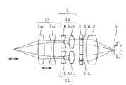
図1は本発明の第一実施形態にかかるステレオ光学系の概略構成を示す説明図、図2は図1のステレオ光学系に備わる時分割光路切り替え手段を示す上面図で、(a)はその一例を示す図、(b)は参考例としての他の例を示す図である。
第一実施形態のステレオ光学系は、2光路形成光学系1と、1つの結像光学系2と、1つの撮像素子3を、内視鏡挿入部先端4に備えている。
2光路形成光学系1は、軸対称に配置された一対のアフォーカル光学系1R,1Lで構成されている。アフォーカル光学系1R(1L)は、像側に凹面を向けた凹レンズ11R(11L)と、凸レンズ12R(12L)とで構成されている。
結像光学系2は、一対のアフォーカル光学系1R,1Lにおける夫々の光路を通る光を共通の領域に結像するように構成されている。
撮像素子3は、結像光学系2の結像位置に配置されている。First Embodiment FIG. 1 is an explanatory view showing a schematic configuration of a stereo optical system according to a first embodiment of the present invention, and FIG. 2 is a top view showing time-division optical path switching means provided in the stereo optical system of FIG. a) is a diagram showing an example thereof, and (b) is a diagram showing anotherexample as a reference example .
The stereo optical system of the first embodiment includes a two-optical path forming
The two-optical path forming
The imaging
The
さらに、第一実施形態のステレオ光学系は、2光路形成光学系1と結像光学系2との間に時分割光路切り替え手段5を備えている。
時分割光路切り替え手段5は、図2(a)に示すように、絞り部材51と、遮蔽部材52とで構成されている。
絞り部材51は、2光路形成光学系1に備わる2つの光路に対応して配置された、2つの開口部51R,51Lを有している。
遮蔽部材52は、開口部51R又は開口部51Lを遮蔽可能に形成された遮蔽板52aと、その一端が遮蔽板に接続し、他端が軸52bを中心に回動可能に絞り部材51に取り付けられたレバー52cとで構成されている。また、遮蔽部材52は、図示しない光路切り替え制御手段に接続されており、光路切り替え制御手段からの制御信号を介して、軸52bを中心に回動し、2つの開口部51R,51Lを時分割で交互に遮蔽することができるように構成されている。
これにより、時分割光路切り替え手段5は、2光路形成光学系1に形成される2つの光路のうちいずれか一方の光路からの光のみが結像光学系2に入射するように、2つの光路を時分割で切り替え可能となっている。Furthermore, the stereo optical system of the first embodiment includes time-division optical path switching means 5 between the two-optical path forming
Time division path switching means 5, as shown in FIG. 2 (a), a
The
The shielding
Thereby, the time division optical path switching means 5 has two optical paths so that only light from one of the two optical paths formed in the two optical path forming
このように構成された第一実施形態の光学系では、計測対象からの光は、一対のアフォーカル光学系1R,1Lを通過して、時分割光路切り替え手段5に入射し、時分割光路切り替え手段5を介して、時分割で2つの光路のうちいずれか一方の光路からの光のみが結像光学系2に入射する。結像光学系2に入射した夫々の光路からの光は、撮像素子4の撮像面における共通領域に結像される。撮像素子4は、時差をもって結像された夫々の光路からの像を撮像する。 In the optical system of the first embodiment configured as described above, the light from the measurement target passes through the pair of afocal
このとき、第一実施形態のステレオ光学系によれば、視差のある2つの光路を通る光を共通の領域に結像させて一つの撮像素子3で撮像するようにしたので、撮像素子3の撮像領域における視差のある夫々の画像の撮像面積を大きくとることができ、高精度な画像情報が得られる。
また、2光路形成光学系1、結像光学系2、撮像素子3を内視鏡挿入部先端4に備えたので、内視鏡挿入部先端4より後続の部材に可撓性を持たせて内視鏡挿入部を曲げることができる。このため、例えば、計測対象が曲がった管である場合や、計測対象の前方に計測の干渉になる物体が存在するような場合等、直線的に挿入できない箇所に位置する計測対象を撮像することができる。
また、2光路形成光学系1に形成される2つの光路のうちいずれか一方の光路からの光のみが結像光学系2に入射するように、2つの光路を時分割で切り替え可能な時分割光路切り替え手段5を備えたので、視差のある夫々の画像を撮像素子で、別々に撮像することができる。視差のある画像を別々に撮像できる結果、その別々に撮像した画像間を相関演算することによって、三角測量の原理で物体の大きさや深さ等を計測することができるようになる。At this time, according to the stereo optical system of the first embodiment, the light passing through the two optical paths having parallax is imaged in a common region and imaged by one
Further, since the optical path forming
In addition, the two optical paths formed in the two optical path forming
このため、第一実施形態のステレオ光学系によれば、視差を大きくとることができるとともに、視差のある夫々の像の撮像面積を大きくとって高精度な画像情報に基づいて計測でき、しかも、直線的に挿入することでは到達できない箇所に位置する計測対象を計測することができるようになる。 For this reason, according to the stereo optical system of the first embodiment, the parallax can be increased, and the imaging area of each image having the parallax can be increased and measured based on highly accurate image information. It becomes possible to measure a measurement object located at a location that cannot be reached by linear insertion.
なお、第一実施形態のステレオ光学系における、時分割光路切り替え手段5は、参考例としては、図2(b)に示すように、2光路形成光学系1に備わる夫々の光路に対応して配置された、1つの開口部51R,51Lを有する2つの絞り部材5R,5Lと、夫々の絞り部材5R,5Lにおける夫々の開口部51R,51Lを時分割で交互に遮蔽可能な2つの遮蔽部材52R,52Lとで構成してもよい。図2(b)中、52aR,52aLは遮蔽板、52bR,52bLは軸、52cR,52cLはレバーである。As areference example , the time division optical path switching means 5 in the stereo optical system of the first embodiment corresponds to each optical path provided in the two optical path forming
また、図示を省略したが、時分割光路切り替え手段5は、参考例としては、2光路形成光学系1に備わる夫々の光路に対応して配置された2つの開口部を有し、2つの開口部を時分割で交互に遮蔽するように構成されたMEMS(Micro Electro Mechanical Systems=機械要素部品、センサー、アクチュエーター、電子回路を、一つのシリコン基板、ガラス基板、有機材料などの上に集積化したデバイス)で構成してもよい。Although not shown, the time-division optical path switching means 5 has, as areference example, two openings that are arranged corresponding to the respective optical paths provided inthe two-optical path forming
また、一対のアフォーカル光学系1R,1Lは、変倍光学系で構成してもよい。このようにすれば、計測対象を拡大して高精度な計測、縮小して広範囲な計測など、用途に応じて最適な計測ができる。 Further, the pair of afocal
図3は第一実施形態の一変形例にかかるステレオ光学系の概略構成を示す説明図である。
図3の変形例のステレオ光学系は、図1の光学系における2光路形成光学系1の物体側に、2光路を含む1つの共通の凸レンズ10を配置して備えている。このように構成された図3の変形例のステレオ光学系によれば、この凸レンズ10の作用によって、視差のある2つの画像が重なる物体距離の範囲が広がるという効果がある。また、物体面にピントを合わせる効果もある。FIG. 3 is an explanatory diagram showing a schematic configuration of a stereo optical system according to a modification of the first embodiment.
Stereoscopic optical system of a modification of FIG. 3, two object side of the optical path forming
図4は第一実施形態の他の変形例にかかるステレオ光学系の概略構成を示す説明図である。
図4の変形例のステレオ光学系は、図3に示した変形例のステレオ光学系における凸レンズ10を、凸レンズ101と凹レンズ102で構成したものである。凸レンズ101と凹レンズ102の間隔は可変となっている。このように構成された図4の変形例のステレオ光学系によれば、図3に示した変形例のステレオ光学系と同様に2つの画像が重なる物体距離の範囲を広げるという効果に加えて、焦点距離を変えることができるのでピントが合う物体距離を変えられるという効果がある。これによって、より最適な計測状態を実現できる。FIG. 4 is an explanatory diagram showing a schematic configuration of a stereo optical system according to another modification of the first embodiment.
Stereoscopic optical system of a modification of FIG. 4, a
第二実施形態
図5は本発明の第二実施形態にかかるステレオ光学系の概略構成を示す説明図で、(a)は通常の計測態様における光学ユニットを含む全体構成を示す図、(b)は視差を小さくして近点を計測するときに先端に取り付ける光学ユニットの一例を示す図、(c)は視差を大きくして遠点を計測するときに先端に取り付ける光学ユニットの一例を示す図である。
第二実施形態のステレオ光学系は、通常の計測態様において、図5(a)に示すように、2光路形成光学系1が内視鏡挿入部先端4に着脱可能に構成されている。
詳しくは、内視鏡挿入部先端4は、先端交換部4aと、先端本体部4bとで構成されている。
先端交換部4aには、2光路形成光学系1が備えられている。また、先端本体部4bには、時分割光路切り替え手段5、結像光学系2、撮像素子3が備えられている。結像光学系2は接合レンズで構成されている。
また、先端交換部4aは、先端本体部4bに対して着脱可能に構成されている。
その他の構成は、第一実施形態のステレオ光学系と略同じである。Second Embodiment FIG. 5 is an explanatory view showing a schematic configuration of a stereo optical system according to a second embodiment of the present invention. (A) is a diagram showing an overall configuration including an optical unit in a normal measurement mode, and (b). Is a diagram showing an example of an optical unit attached to the tip when measuring a near point with a reduced parallax, (c) is a diagram showing an example of an optical unit attached to the tip when measuring a far point with a larger parallax It is.
The stereo optical system of the second embodiment is configured so that the two-optical path forming
Specifically, the endoscope insertion portion
The
The
Other configurations are substantially the same as the stereo optical system of the first embodiment.
撮像領域全体に視差のある像を夫々得ようとする場合、図5(a)に示した2光路形成光学系1を用いれば、視差を大きくとることができる。しかし、図5(a)に示した2光路形成光学系1を備えた構成を用いて近点の計測をすると、視差が大きくなりすぎて実用的でなくなる。また、計測用途によっては、先端の径の大きさを大きくしても計測に支障が生じず、さらに視差を大きくして観察することが望まれる場合がある。 When trying to obtain images with parallax in the entire imaging region, the parallax can be increased by using the two-path forming
しかるに、第二実施形態のステレオ光学系によれば、2光路形成光学系を着脱可能にしたので、観察用途に応じて適した視差の光学系に交換することができる。 However, according to the stereo optical system of the second embodiment, since the two-optical path forming optical system is made detachable, it can be replaced with a parallax optical system suitable for observation purposes.
例えば、視差を小さくして近点を観察する場合には、図5(b)に示すような光学系1’を備えた先端交換部4aを、先端本体部4bに装着することができるようになっている。
図5(b)に示す光学系1’は、像側に凹面を向けた凹レンズ11’と、凸レンズ12’とで構成されている。図5(b)に示す光学系1’では、先端本体部4bに装着したときの視差d1が、図5(a)に示す光学系1を先端本体部4bに装着したときの視差dに比べて、小さくなっている。For example, when observing a near point with a reduced parallax, the
The
また、例えば、視差を大きくして遠点を観察する場合には、図5(c)に示すような光学系1”を備えた先端交換部4aを、先端本体部4bに装着することができるようになっている。
図5(c)に示す光学系1”は、凸レンズ11”と、物体側に凹面を向けた凹レンズ12”とで構成されている。
図5(c)に示す光学系1”では、先端本体部4bに装着したときの視差d2が、図5(a)に示す光学系1を先端本体部4bに装着したときの視差dに比べて、大きくなっている。For example, when observing a distant point with a large parallax, the
An
In the
図5(b),図5(c)に示す先端光学部4a内の光学系は、単一の光学系であり、2本の光軸を有しない。しかし、時分割光路切り替え手段5による光路の切り替えにより、瞳が時分割に分割される。このため、結像光学系2を介して、撮像素子3の撮像領域全体に、時分割で瞳分割された視差のある像が結像され、計測に適した画像が得られる。
その他の作用効果は、第一実施形態のステレオ光学系と略同じである。The optical system in the tip
Other functions and effects are substantially the same as those of the stereo optical system of the first embodiment.
第三実施形態
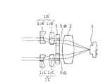
図6は本発明の第三実施形態にかかるステレオ光学系の概略構成を示す説明図である。
第三実施形態のステレオ光学系では、2光路形成光学系1としての一対のアフォーカル光学系1R,1Lと、時分割光路切り替え手段5との間に、光路間隔変換手段としての軸対称な楔型プリズム6が設けられている。軸対称な楔形プリズム6は、時分割光路切り替え手段5の2つの光路の間隔を拡大する機能を有している。一対のアフォーカル光学系1R,1Lは、軸対称な楔形プリズム6により拡大された2つの光路に対応した位置に配置されている。
その他の構成は、第一実施形態のステレオ光学系と略同じである。Third Embodiment FIG. 6 is an explanatory diagram showing a schematic configuration of a stereo optical system according to a third embodiment of the present invention.
In the stereo optical system according to the third embodiment, an axially symmetric wedge as an optical path interval converting unit is provided between the pair of afocal
Other configurations are substantially the same as the stereo optical system of the first embodiment.
このように構成された第三実施形態のステレオ光学系によれば、視差を大きくとることができる。
その他の作用効果は、第一実施形態のステレオ光学系と略同じである。According to the stereo optical system of the third embodiment configured as described above, a large parallax can be obtained.
Other functions and effects are substantially the same as those of the stereo optical system of the first embodiment.
第四実施形態
図7は本発明の第四実施形態にかかるステレオ光学系の概略構成を示す説明図である。
第四実施形態のステレオ光学系では、2光路形成光学系1としての一対のアフォーカル光学系1R’,1L’がステレオ光学系の光軸に対称に偏心して構成され、光路間隔変換手段として2つの光路の間隔を拡大する機能を有している。
アフォーカル光学系1R’(1L’)は、像側に凹面を向けた凹レンズ11R’(11L’)と、凸レンズ12R’(12L’)とで構成されている。像側に凹面を向けた凹レンズ11R’(11L’)は、図1に示した像側に凹面を向けた凹レンズ11R(11L)の光軸より内側部分で構成されている。凸レンズ12R’(12L’)は、図1に示した凸レンズ12R(12L)の光軸より内側部分で構成されている。
その他の構成は、第一実施形態のステレオ光学系と略同じである。Fourth Embodiment FIG. 7 is an explanatory diagram showing a schematic configuration of a stereo optical system according to a fourth embodiment of the present invention.
In the stereo optical system of the fourth embodiment, a pair of afocal
The afocal
Other configurations are substantially the same as the stereo optical system of the first embodiment.
このように構成された第四実施形態のステレオ光学系によれば、視差を大きくとることができる。しかも、第四実施形態のステレオ光学系によれば、アフォーカル光学系1R’(1L’)が、図1に示したアフォーカル光学系1R(1L)の光軸から内側部分で構成したので、視差を大きくし且つステレオ光学系全体の径の大型化を抑えることができる。
その他の作用効果は、第一実施形態のステレオ光学系と略同じである。According to the stereo optical system of the fourth embodiment configured as described above, a large parallax can be obtained. In addition, according to the stereo optical system of the fourth embodiment, the afocal
Other functions and effects are substantially the same as those of the stereo optical system of the first embodiment.
第五実施形態
図8は本発明の第五実施形態にかかるステレオ光学系の概略構成を示す説明図である。
第五実施形態のステレオ光学系は、2光路形成光学系1が、可変焦点レンズ13を有している。
即ち、図8の例では、2光路形成光学系1は、一対のアフォーカル光学系1R,1Lで構成されており、アフォーカル光学系1R(1L)は、像側に凹面を向けた凹レンズ11R(11L)と、凸レンズ12R(12L)と、可変焦点レンズ13とで構成されている。
その他の構成は、第一実施形態のステレオ光学系と略同じである。Fifth Embodiment FIG. 8 is an explanatory diagram showing a schematic configuration of a stereo optical system according to a fifth embodiment of the present invention.
Stereoscopic optical system of the fifth embodiment, second optical path forming
That is, in the example of FIG. 8, the two-optical path forming
Other configurations are substantially the same as the stereo optical system of the first embodiment.
このように構成された第五実施形態のステレオ光学系によれば、2光路形成光学系1を視差の大きな光学系として構成しても、近点に焦点をあわせ易くなる。このため、立体計測可能な範囲を増やすことができる。
その他の作用効果は、第一実施形態のステレオ光学系と略同じである。
なお、図8の例では、可変焦点レンズ13を凸レンズ12R(12L)の像側に配置したが、可変焦点レンズ13を凹レンズ11R(11L)の物体側に配置してもよい。According to the stereo optical system of the fifth embodiment configured as above, even if the two-optical path forming
Other functions and effects are substantially the same as those of the stereo optical system of the first embodiment.
In the example of FIG. 8, a variable-
第六実施形態
図9は本発明の第六実施形態にかかるステレオ光学系の概略構成を示す説明図である。
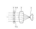
第六実施形態のステレオ光学系は、時分割光路切り替え手段5と、1つの結像光学系2と、1つの撮像素子3とで構成されている。
時分割光路切り替え手段5は、夫々の光路に対応して配置された2つの開口部51R,51Lを有し、遮蔽部材(図9において図示省略)を介して2つの開口部を時分割で交互に遮蔽することによって2つの光路を形成する。このため、時分割光路切り替え手段5は、それ自体で2光路形成光学系としての機能を備えている。
その他の構成は、第一実施形態のステレオ光学系と略同じである。
なお、結像光学系2は単レンズでなく複数のレンズで構成してもよい。Sixth Embodiment FIG. 9 is an explanatory diagram showing a schematic configuration of a stereo optical system according to a sixth embodiment of the present invention.
The stereo optical system according to the sixth embodiment includes time-division optical path switching means 5, one imaging
The time-division optical path switching means 5 has two
Other configurations are substantially the same as the stereo optical system of the first embodiment.
The imaging
このように構成された第六実施形態のステレオ光学系によれば、時分割光路切り替え手段5が、2光路形成光学系としての機能を備えているので、少ない部材で、視差のある夫々の像の撮像面積を大きくとって高精度な画像情報に基づいて計測でき、しかも、直線的に挿入することでは到達できない箇所に位置する計測対象を計測することができるようになる。 According to the stereo optical system of the sixth embodiment configured as described above, the time-division optical path switching means 5 has a function as a two-optical path forming optical system. It is possible to measure based on highly accurate image information by taking a large imaging area, and to measure a measurement object located at a location that cannot be reached by linear insertion.
次に、上記各実施形態において説明したステレオ光学系を用いた、ステレオ計測装置の実施形態について説明する。
第七実施形態
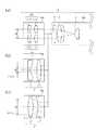
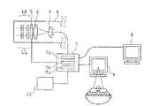
図10は本発明の第七実施形態にかかる、ステレオ光学系を用いたステレオ計測装置の概略構成を示す説明図である。
第七実施形態のステレオ計測装置は、図1〜図9に示した第一実施形態〜第六実施形態のいずれかのステレオ光学系を内視鏡挿入部先端4に備えた内視鏡(全体図は省略)と、プロセッサー7と、計測値表示装置8とを有して構成されている。
プロセッサー7は、計測値算出処理部7aを有している。計測値算出処理部7aは、時分割光路切り替え手段5の光路切り替え動作に連動し、撮像素子3を介して時分割で撮像された夫々の光路を通る計測対象の画像を用いて、相関演算して各画像上での対応する計測点のズレ量を算出し、算出したズレ量を用いて計測対象についての所定の計測値(例えば、計測対象の大きさや深さ)を算出する機能を備えている。
計測値表示装置8は、計測値算出処理部7aを介して算出された所定の計測値を表示するモニターで構成されている。Next, an embodiment of a stereo measurement apparatus using the stereo optical system described in the above embodiments will be described.
Seventh Embodiment FIG. 10 is an explanatory diagram showing a schematic configuration of a stereo measurement apparatus using a stereo optical system according to a seventh embodiment of the present invention.
The stereo measurement device of the seventh embodiment is an endoscope (the whole) in which the stereo optical system of any one of the first to sixth embodiments shown in FIGS. (Not shown), a
The
The measurement value display device 8 includes a monitor that displays a predetermined measurement value calculated via the measurement value
このように構成された第七実施形態のステレオ計測装置では、計測対象からの光は、一対のアフォーカル光学系1R,1Lを通過して、時分割光路切り替え手段5に入射し、時分割光路切り替え手段5を介して、時分割で2つの光路のうちいずれか一方の光路からの光のみが結像光学系2に入射する。結像光学系2に入射した夫々の光路からの光は、撮像素子4の撮像面における共通領域に結像される。撮像素子4は、時差をもって結像された夫々の光路からの像を撮像する。
このとき、プロセッサー7の計測値算出処理部7aが、時分割光路切り替え手段5の光路切り替え動作に連動して、撮像素子3を介して時分割で撮像された夫々の光路を通る計測対象の画像を用いて、相関演算して計測対象についての所定の計測値(例えば、計測対象の大きさや深さ)を算出する。そして、計測値表示装置8が、計測値算出処理部7aを介して算出された所定の計測値を表示する。In the stereo measurement apparatus of the seventh embodiment configured as described above, the light from the measurement object passes through the pair of afocal
At this time, the measurement value
第八実施形態
図11は本発明の第八実施形態にかかる、ステレオ光学系を用いたステレオ計測装置の概略構成を示す説明図である。
第八実施形態のステレオ計測装置は、図1〜図9に示した第一実施形態〜第六実施形態のいずれかのステレオ光学系を内視鏡挿入部先端4に備えた内視鏡(全体図は省略)と、プロセッサー7と、計測値表示装置8と、画像表示装置9と、光路切り替え動作指示手段10を有して構成されている。
プロセッサー7は、計測値算出処理部7aと、光路切り替え動作制御部7bと、画像処理部7cを有している。Eighth Embodiment FIG. 11 is an explanatory diagram showing a schematic configuration of a stereo measurement apparatus using a stereo optical system according to an eighth embodiment of the present invention.
The stereo measurement apparatus of the eighth embodiment is an endoscope (the whole) in which the stereo optical system of any one of the first to sixth embodiments shown in FIGS. (Not shown), a
The
計測値算出処理部7aは、時分割光路切り替え手段5の光路切り替え動作に連動し、撮像素子3を介して時分割で撮像された夫々の光路を通る計測対象の画像を用いて、相関演算して計測対象についての所定の計測値(例えば、計測対象の大きさや深さ)を算出する機能を備えている。
光路切り替え動作制御部7bは、光路切り替え動作指示手段10からの指示に基づいて時分割光路切り替え手段5による光路切り替え動作を制御する機能を備えている。
画像処理部7cは、ステレオ光学系の撮像素子3を介して撮像された計測対象の画像について次のような処理を行う。即ち、光路切り替え動作指示手段10から第1の指示モードが指示されたときには、時分割光路切り替え手段5を介して時分割に分割され撮像素子3で撮像された夫々の光路からの画像データを用いて、3次元画像を作成する。また、光路切り替え動作指示手段10から第2の指示モードが指示されたときには、時分割光路切り替え手段5を介して切り替えられ撮像素子3で撮像されたいずれか一方の光路からの画像データのみを用いて2次元画像を作成する。The measurement value
The optical path switching
The image processing unit 7c performs the following process on the measurement target image captured through the
計測値表示装置8は、計測値算出処理部7aを介して算出された所定の計測値を表示するモニターで構成されている。
画像表示手段9は、画像処理部7cを介して画像処理された計測対象の画像を表示するモニターで構成されている。
光路切り替え動作指示手段10は、画面表示又は機械式のボタン又はスイッチ等を用いて、時分割光路切り替え手段5による交互の光路への光路切り替えを所定ピッチで連続的に行う第1の指示モードと、時分割光路切り替え手段5によるいずれか一方の光路への光路切り替えを行う第2の指示モードとのいずれか一方を選択して指示可能に構成されている。The measurement value display device 8 includes a monitor that displays a predetermined measurement value calculated via the measurement value
The image display means 9 includes a monitor that displays an image to be measured that has been subjected to image processing via the image processing unit 7c.
The optical path switching operation instruction means 10 is a first instruction mode in which the optical path switching to the alternate optical path by the time-division optical path switching means 5 is continuously performed at a predetermined pitch by using a screen display or a mechanical button or switch. The time-division optical path switching means 5 is configured to be able to instruct by selecting any one of the second instruction modes for switching the optical path to any one of the optical paths.
このように構成された第八実施形態のステレオ計測装置では、計測対象からの光は、一対のアフォーカル光学系1R,1Lを通過して、時分割光路切り替え手段5に入射する。 In the stereo measurement apparatus of the eighth embodiment configured as described above, light from the measurement target passes through the pair of afocal
ここで、計測対象についての2次元画像観察を行う場合、操作者は、光路切り替え動作指示手段10を第2の指示モードに設定する。
第2の指示モードに設定した場合、時分割光路切り替え手段5は、光路切り替え動作制御部7bを介して、2つの光路のうちいずれか一方の光路への光路切り替えを行うように駆動する。時分割光路切り替え手段5に入射した2つの光路からの光のうちいずれか一方の光路からの光のみが結像光学系2に入射する。結像光学系2に入射した一方の光路からの光は、撮像素子3の撮像面における共通領域に結像される。次いで、画像処理部7cが、撮像素子3で撮像されたいずれか一方の光路からの画像データを用いて2次元画像を作成する。次いで、画像表示手段9が、画像処理部7cを介して画像処理された計測対象の画像を表示する。
これにより、操作者は、計測対象の2次元画像を観察することができる。Here, when performing two-dimensional image observation of the measurement target, the operator sets the optical path switching operation instruction means 10 to the second instruction mode.
When the second instruction mode is set, the time-division optical
Thereby, the operator can observe the two-dimensional image to be measured.
一方、計測対象についての3次元計測及び3次元観察を行う場合、操作者は、光路切り替え動作指示手段10を第1の指示モードに設定する。
第1の指示モードに設定した場合、時分割光路切り替え手段5は、光路切り替え動作制御部7bを介して、交互の光路への光路切り替えを所定ピッチで連続的に行うように駆動する。時分割光路切り替え手段5に入射した2つの光路からの光のうちいずれか一方の光路からの光のみが時分割で結像光学系2に入射する。結像光学系2に入射した夫々の光路からの光は、撮像素子3の撮像面における共通領域に結像される。撮像素子3は、時差をもって結像された夫々の光路からの像を撮像する。
このとき、プロセッサー7の計測値算出処理部7aが、時分割光路切り替え手段5の光路切り替え動作に連動して、撮像素子3を介して時分割で撮像された夫々の光路を通る計測対象の画像を用いて、相関演算して計測対象についての所定の計測値(例えば、計測対象の大きさや深さ)を算出する。そして、計測値表示装置8が、計測値算出処理部7aを介して算出された所定の計測値を表示する。
また、画像処理部7cは、撮像素子3で撮像された夫々の光路からの画像データを用いて3次元画像を作成する。次いで、画像表示手段9が、画像処理部7cを介して画像処理された計測対象の画像を表示する。
これにより、操作者は、ステレオ計測値を得るとともに計測対象の3次元画像を観察することができる。On the other hand, when performing three-dimensional measurement and three-dimensional observation on the measurement target, the operator sets the optical path switching operation instruction means 10 to the first instruction mode.
When set to the first instruction mode, the time-division optical path switching means 5 drives the optical path switching
At this time, the measurement value
In addition, the image processing unit 7 c creates a three-dimensional image using image data from each optical path imaged by the
Thus, the operator can obtain a stereo measurement value and observe a three-dimensional image to be measured.
なお、上記構成では、光路切り替え動作指示手段10を第1の指示モードに設定したときの、時分割光路切り替え手段5による交互の光路への光路の切り替えを、所定ピッチで連続的に行うようにしたが、1回のみ行うようにしてもよい。
あるいは、光路切り替え動作指示手段10を、第1の指示モードに設定する際に、さらに交互の光路への光路の切り替えのピッチ、回数を設定できるようにしてもよい。In the above configuration, when the optical path switching
Alternatively, when the optical path switching
また、光路切り替え動作指示手段10を、例えば、押しボタンで構成し、押しボタンが押されないときには第2の指示モードを設定し、押しボタンが押されている間だけ第1の指示モードを設定するようにしてもよい。 Further, the optical path switching operation instruction means 10 is constituted by, for example, a push button, the second instruction mode is set when the push button is not pressed, and the first instruction mode is set only while the push button is pressed. You may do it.
工業用内視鏡を用いて計測に重点をおいた検査を行う場合、計測対象の2次元画像が得られれば十分で、3次元画像を観察することが却って検査者の眼に負担をかけることになることがある。
そこで、上述のように、光路切り替え動作指示手段10を、押しボタンを押した間だけ第1の指示モードが設定されるようにすれば、常時、2次元画像が表示されるようにすることができ、立体計測を行う場合に一瞬だけ光路を切り替えて他方の画像を取り込むようにすることができるので、検査者の眼の負担を軽減することができる。When performing an inspection with an emphasis on measurement using an industrial endoscope, it is sufficient if a two-dimensional image to be measured is obtained, and observing the three-dimensional image places a burden on the eye of the examiner. May be.
Therefore, as described above, if the first instruction mode is set for the optical path switching operation instruction means 10 only while the push button is pressed, a two-dimensional image can always be displayed. In addition, when performing stereo measurement, the optical path can be switched for a moment and the other image can be captured, thereby reducing the burden on the eye of the examiner.
あるいは、第八実施形態のステレオ計測装置において、光路切り替え動作指示手段10を介して第1の指示モードが設定されたときに、画像表示装置9に、時分割で撮像された夫々の光路を通る計測対象の画像を分割して2画面表示するようにしてもよい。
また、あるいは、第八実施形態のステレオ計測装置において、光路切り替え動作指示手段10を介して第1の指示モードが設定されたときに、画像表示装置9に、時分割で撮像された夫々の光路を通る計測対象の画像を所望の時間ごとに切り替えて表示するようにしてもよい。その場合には、所望の時間は、別途設定できるようにするとよい。
このようにしても、常時、2次元画像が表示されるようにすることができるので、検査者の眼の負担を軽減することができる。Alternatively, in the stereo measurement apparatus of the eighth embodiment, when the first instruction mode is set via the optical path switching operation instruction means 10, the image display apparatus 9 passes through each optical path imaged in time division. The image to be measured may be divided and displayed on two screens.
Alternatively, in the stereo measurement apparatus according to the eighth embodiment, when the first instruction mode is set via the optical path switching operation instruction means 10, each optical path captured in time division on the image display apparatus 9 The image to be measured passing through may be switched and displayed every desired time. In that case, the desired time may be set separately.
Even in this case, since a two-dimensional image can be displayed at all times, the burden on the eye of the examiner can be reduced.
さらに、第七実施形態、第八実施形態のステレオ計測装置の構成における時分割に光路を切り替えて得た夫々の光路を通る画像を用いて、次のような汚れチェック機能を付加させるのが好ましい。
例えば、プロセッサー7に、汚れチェック処理部(図示省略)を付加し、汚れチェック処理部を、撮像素子3を介して時分割で撮像された夫々の光路を通る計測対象の画像について、常時同じ位置に同じ像が撮像されているか否かを検査し、撮像されている場合にはステレオ計測用光学系にゴミや汚れがあるものとして、モニター等に警告標識を表示させるように構成するとよい。Furthermore, it is preferable to add the following dirt check function using images passing through the respective optical paths obtained by switching the optical paths in the time division in the configuration of the stereo measurement apparatus of the seventh embodiment and the eighth embodiment. .
For example, a stain check processing unit (not shown) is added to the
例えば、撮像素子の撮像面にゴミ等が付着していると、計測対象を撮像しても高精度な計測を行うことができない。
しかるに、上述のような汚れチェック機能を備えておけば、ゴミ等の汚れが生じてもすぐに気付いて除去することができるようになるので、高精度な計測に支障を与えずに済む。
なお、汚れチェック機能の駆動は、ステレオ計測装置の起動時に自動起動するようにするとよい。あるいは、第八実施形態のステレオ計測装置における光路切り替え動作指示手段10に、汚れチェック機能を駆動するためのモードを付加してもよい。For example, if dust or the like is attached to the imaging surface of the image sensor, high-precision measurement cannot be performed even if the measurement target is imaged.
However, if the dirt check function as described above is provided, even if dirt such as dust is generated, it can be immediately noticed and removed, so that there is no need to hinder high-precision measurement.
Note that the dirt check function may be automatically activated when the stereo measurement apparatus is activated. Alternatively, a mode for driving the dirt check function may be added to the optical path switching operation instruction means 10 in the stereo measurement apparatus of the eighth embodiment.
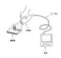
また、本発明のステレオ光学系は、図12に示すような手持ちの観察計測装置(ビデオ顕微鏡)や、図13に示すロボットアームの先端に取り付けられる計測機能付きセンサーなどの装置にも適用可能である。このような装置に本発明のステレオ光学系を適用すれば、本発明のステレオ光学系が小型であることによって、上記の各装置もコンパクトで取り扱いがしやすいものとすることができる。 The stereo optical system of the present invention can also be applied to devices such as a hand-held observation measurement device (video microscope) as shown in FIG. 12 and a sensor with a measurement function attached to the tip of a robot arm as shown in FIG. is there. When the stereo optical system of the present invention is applied to such a device, the above-described devices can be made compact and easy to handle because the stereo optical system of the present invention is small.
以上、本発明のステレオ光学系、並びにそれを用いたステレオ計測用光学装置、ステレオ計測装置及びステレオ観察装置の実施形態について説明したが、本発明のステレオ光学系と上記各装置は、これらの実施形態の構成に限定されるものではない。例えば、各実施形態における特徴的な構成を組み合わせて本発明のステレオ光学系、並びにそれを用いたステレオ計測用光学装置、ステレオ計測装置及びステレオ観察装置を構成してもよい。 The stereo optical system of the present invention and the embodiments of the stereo measurement optical apparatus, stereo measurement apparatus, and stereo observation apparatus using the stereo optical system have been described above. It is not limited to the configuration of the form. For example, the stereo optical system of the present invention, a stereo measurement optical device, a stereo measurement device, and a stereo observation device using the stereo optical system of the present invention may be configured by combining the characteristic configurations in the embodiments.
本発明は、機械内部の損傷や欠損、患部等の計測対象を定量的に把握するためのステレオ計測を行う工業、医療の分野に有用である。 INDUSTRIAL APPLICABILITY The present invention is useful in the industrial and medical fields that perform stereo measurement for quantitatively grasping measurement objects such as damage and defects inside a machine and an affected part.
1 2光路形成光学系
1L、1R、1L’、1R’ アフォーカル光学系
11L、11R、11’、12”、11L’、11R’、102 凹レンズ
12L、12R、12’、11”、12L’、12R’、10、101 凸レンズ
1’、1” 光学系
13 可変焦点レンズ
2 結像光学系
3 撮像素子
4 内視鏡挿入部先端
4a 先端交換部
4b 先端本体部
5 時分割光路切り替え手段
51、5L、5R 絞り部材
51L、51R 開口部
52、52L、52R 蔽部材
52a、52aL、52aR 遮蔽板
52b、52bL、52bR 軸
52c、52cL、52cR レバー
6 軸対称な楔形プリズム
7 プロセッサー
7a 計測値算出処理部
7b 光路切り替え動作制御部
7c 画像処理部
8 計測値表示装置
9 画像表示装置
10 光路切り替え動作指示手段
51L、51R 負レンズ
52 正レンズ群
52L、52R 絞り開口部
53 対物光学系
54L、54R 撮像素子
60L,60R レンズ
60 第1ユニット
61 第2ユニット
62 第3ユニット
63 撮像ユニット
63a 撮像素子
71L、71R 負レンズ
72L、72R 正レンズ
73 正レンズ群
74 対物光学系
75 撮像素子
81 瞳分割手段
81a、81b 開口部
82 結像光学系
83 撮像素子
91 対物光学系
911R、911L 群光学系
912 後群光学系
92a、92b、92c リレーレンズ系
93 瞳分割結像手段
93a、93a’ 瞳結像レンズ系
93bL、93bR ミラー部
93cL、93cR、93c’ 結像レンズ系
94L、94R、94’ 撮像素子
95L、95R、96L、96R 像1 2 optical path forming
1 1 L, 1 1 R, 1 1 ', 1 2 ", 1 1 L', 1 1 R ', 1 02 concave lens1 2 L, 1 2 R, 1 2', 1 1", 1 2 L ', 12 R ', 10, 101 convex lens 1', 1 "optical system 13 variable focus lens 2 forming optical system 3 imaging element 4 endoscope insertion portion distal end 4a distal exchange section 4b distal body portion 5:00 split optical path Switching means 51 , 5L, 5R Aperture member 51 L, 51 R Opening 52 , 52 L, 52 R Shielding member 52 a, 52 aL, 52 aR Shielding plate 52 b, 52 bL, 52 bR Axis 52 c, 52 cL, 52 cR Lever 6 Axisymmetric wedge-shaped prism 7 Processor 7a Measurement value calculation processing unit 7b Optical path switching operation control unit 7c Image processing unit 8 Measurement value display device 9 Image display Device 10 Optical path switching operation instruction means 51L, 51R Negative lens 52 Positive lens group 52L, 52R Aperture aperture 53 Pair Object optical system 54L, 54R Imaging element 60L, 60R Lens 60 First unit 61 Second unit 62 Third unit 63 Imaging unit 63a Imaging element 71L, 71R Negative lens 72L, 72R Positive lens 73 Positive lens group 74 Objective optical system 75 Imaging Element 81 Pupil division means 81a, 81b Aperture 82 Imaging optical system 83 Imaging element 91 Objective optical system 911 R, 911 L Group optical system 912 Rear group optical system 92a, 92b, 92c Relay lens system 93 Pupil division Image means 93a, 93a ′ Pupil imaging lens system 93bL, 93bR Mirror part 93cL, 93cR, 93c ′ Imaging lens system 94L, 94R, 94 ′ Imaging elements 95L, 95R, 96L, 96R
Claims (15)
Translated fromJapanese前記2光路形成光学系に形成される2つの光路のうちいずれか一方の光路からの光のみが前記結像光学系に入射するように、該2つの光路を時分割で切り替え可能な時分割光路切り替え手段を備え、
前記時分割光路切り替え手段は、前記2光路形成光学系に備わる2つの光路に対応して配置された2つの開口部を有する1つの絞り部材と、前記絞り部材における2つの開口部を時分割で交互に遮蔽可能な遮蔽部材とからなり、
前記遮蔽部材は、前記絞り部材における1つの開口部を遮蔽可能な大きさに形成された遮蔽板と、その一端が前記遮蔽板に接続し、他端が軸を中心に回動可能に前記絞り部材に取り付けられたレバーとを有し、前記軸を中心とした前記レバーの回動により前記遮蔽板が前記絞り部材における2つの開口部を交互に遮蔽することができるように構成されていることを特徴とするステレオ光学系。Two optical path forming optical systems that form two optical paths with parallax, one imaging optical system that forms an image of light passing through each optical path in the two optical path forming optical system in a common region, and the imaging optical system A stereo optical system having one imaging element arranged at the imaging position at the distal end of the endoscope insertion portion,
A time division optical path capable of switching the two optical paths in a time division manner so that only light from one of the two optical paths formed in the two optical path formation optical system is incident on the imaging optical system. Switching means,
The time-division optical path switching unit is configured to time-divide one aperture member having two apertures arranged corresponding to two optical paths provided in the two-optical path forming optical system, and two apertures in the aperture member. It consists of shielding members that can be shielded alternately,
The shielding member includes a shielding plate formed in a size capable of shielding one opening in the diaphragm member, one end thereof connected to the shielding plate, and the other end pivotable about an axis. A lever attached to the member, and configured so that the shielding plate can alternately shield the two openings of the aperture member by rotating the lever around the shaft. Stereo optical system characterized by
前記一対のアフォーカル光学系は、前記軸対称な楔形プリズムを介して拡大された2つの光路に対応した位置に配置されていることを特徴とする請求項5に記載のステレオ光学系。The optical path interval conversion means comprises an axisymmetric wedge prism disposed between the pair of afocal optical systems and the time-division optical path switching means,
6. The stereo optical system according to claim5 , wherein the pair of afocal optical systems are arranged at positions corresponding to two optical paths enlarged through the axisymmetric wedge-shaped prism.
前記光路間隔変換手段が、前記結像光学系の光軸に対称に偏心した一対のアフォーカル光学系からなることを特徴とする請求項5に記載のステレオ光学系。The pair of afocal optical systems are decentered symmetrically with respect to the optical axis of the imaging optical system,
6. The stereo optical system according to claim5 , wherein the optical path interval conversion means includes a pair of afocal optical systems that are decentered symmetrically with respect to the optical axis of the imaging optical system.
前記ステレオ光学系の前記撮像素子を介して時分割で撮像された前記夫々の光路を通る計測対象の画像を用いて、相関演算して各画像上での対応する計測点のズレ量を算出し、算出したズレ量を用いて該計測対象についての所定の計測値を算出する計測値算出処理部と、
前記計測値算出処理部により算出した所定の計測値を表示する計測値表示手段、
を有するステレオ計測装置。The stereo optical system according to any one of claims 1 to9 ,
Using the images of the measurement target passing through the respective optical paths imaged in a time-division manner through the imaging element of the stereo optical system, the correlation calculation is performed to calculate the amount of deviation of the corresponding measurement point on each image. A measurement value calculation processing unit that calculates a predetermined measurement value for the measurement object using the calculated deviation amount;
A measurement value display means for displaying a predetermined measurement value calculated by the measurement value calculation processing unit;
Stereo measurement apparatus having
前記画像処理部を介して画像処理された計測対象の画像を表示する画像表示手段を有することを特徴とする請求項11に記載のステレオ計測装置。Furthermore, an image processing unit that performs a predetermined process on the measurement target image captured through the imaging element of the stereo optical system;
Stereo measurement device according to claim 11, characterized in that it comprises an image display means for displaying an image of the measurement object on which an image has been processed through the image processing unit.
前記光路切り替え動作指示手段からの指示に基づいて前記時分割光路切り替え手段による光路切り替え動作を制御する光路切り替え動作制御部を有し、
前記光路切り替え動作指示手段は、前記時分割光路切り替え手段による交互の光路への光路切り替えを行う第1の指示モードと、前記時分割光路切り替え手段によるいずれか一方の光路への光路切り替え行う第2の指示モードとのいずれか一方を選択して指示可能に構成されていることを特徴とする請求項12に記載のステレオ計測装置。Further, an optical path switching operation instruction means for instructing an optical path switching operation by the time division optical path switching means,
An optical path switching operation control unit for controlling an optical path switching operation by the time-division optical path switching unit based on an instruction from the optical path switching operation instruction unit;
The optical path switching operation instruction means includes a first instruction mode for performing optical path switching to alternate optical paths by the time division optical path switching means, and a second for performing optical path switching to one of the optical paths by the time division optical path switching means. stereo measurement device according to claim 12, characterized in that is configured to be instructed by selecting either the instruction modes.
Priority Applications (2)
| Application Number | Priority Date | Filing Date | Title |
|---|---|---|---|
| JP2008305114AJP4750175B2 (en) | 2008-11-28 | 2008-11-28 | Stereo optical system, and stereo measurement optical apparatus, stereo measurement apparatus, and stereo observation apparatus using the same |
| US12/653,928US8648896B2 (en) | 2008-11-28 | 2009-12-17 | Stereoscopic optical system, and optical apparatus for stereoscopic measurement, stereoscopic measurement apparatus and stereoscopic observation apparatus each using the same |
Applications Claiming Priority (1)
| Application Number | Priority Date | Filing Date | Title |
|---|---|---|---|
| JP2008305114AJP4750175B2 (en) | 2008-11-28 | 2008-11-28 | Stereo optical system, and stereo measurement optical apparatus, stereo measurement apparatus, and stereo observation apparatus using the same |
Publications (2)
| Publication Number | Publication Date |
|---|---|
| JP2010128354A JP2010128354A (en) | 2010-06-10 |
| JP4750175B2true JP4750175B2 (en) | 2011-08-17 |
Family
ID=42328770
Family Applications (1)
| Application Number | Title | Priority Date | Filing Date |
|---|---|---|---|
| JP2008305114AActiveJP4750175B2 (en) | 2008-11-28 | 2008-11-28 | Stereo optical system, and stereo measurement optical apparatus, stereo measurement apparatus, and stereo observation apparatus using the same |
Country Status (2)
| Country | Link |
|---|---|
| US (1) | US8648896B2 (en) |
| JP (1) | JP4750175B2 (en) |
Cited By (6)
| Publication number | Priority date | Publication date | Assignee | Title |
|---|---|---|---|---|
| WO2015001852A1 (en) | 2013-07-04 | 2015-01-08 | オリンパス株式会社 | Endoscope |
| US11058287B2 (en) | 2017-07-03 | 2021-07-13 | Olympus Corporation | Optical system for stereoscopic vision and image pickup apparatus using the same |
| US11156809B2 (en) | 2017-05-16 | 2021-10-26 | Olympus Corporation | Optical system for stereoscopic vision and endoscope using the same |
| US11187886B2 (en) | 2017-09-29 | 2021-11-30 | Olympus Corporation | Optical system for stereoscopic vision and image pickup apparatus using the same |
| US11478134B2 (en) | 2017-04-13 | 2022-10-25 | Olympus Corporation | Stereoscopic-vision endoscope optical system and endoscope using the same |
| WO2023139251A1 (en)* | 2022-01-24 | 2023-07-27 | Karl Storz Se & Co. Kg | Measuring device and measuring method for checking a measured-image state |
Families Citing this family (69)
| Publication number | Priority date | Publication date | Assignee | Title |
|---|---|---|---|---|
| US8496575B2 (en)* | 2006-11-14 | 2013-07-30 | Olympus Corporation | Measuring endoscope apparatus, program and recording medium |
| WO2011160200A1 (en)* | 2010-06-25 | 2011-12-29 | Isee3D Inc. | Method and apparatus for generating three-dimensional image information |
| EP2630543B1 (en) | 2010-10-18 | 2019-10-09 | Reach3D Medical LLC. | A STEREOSCOPIC OPTIC Adapter |
| US9635347B2 (en)* | 2010-11-15 | 2017-04-25 | Reach3D Medical Llc | Stereoscopic relay optics |
| US8764635B2 (en)* | 2010-11-24 | 2014-07-01 | Olympus Corporation | Endoscope apparatus |
| GB201107225D0 (en)* | 2011-04-29 | 2011-06-15 | Peira Bvba | Stereo-vision system |
| JP5844118B2 (en)* | 2011-10-31 | 2016-01-13 | 日本電産コパル株式会社 | Imaging device |
| JP5427323B2 (en)* | 2012-01-18 | 2014-02-26 | オリンパスメディカルシステムズ株式会社 | Stereoscopic endoscope optical system |
| WO2013114725A1 (en)* | 2012-02-01 | 2013-08-08 | オリンパスメディカルシステムズ株式会社 | Optical system for stereo-endoscope |
| US9642606B2 (en) | 2012-06-27 | 2017-05-09 | Camplex, Inc. | Surgical visualization system |
| US9615728B2 (en) | 2012-06-27 | 2017-04-11 | Camplex, Inc. | Surgical visualization system with camera tracking |
| JP6017198B2 (en) | 2012-06-28 | 2016-10-26 | オリンパス株式会社 | Endoscope apparatus and program |
| JP5996319B2 (en)* | 2012-07-31 | 2016-09-21 | オリンパス株式会社 | Stereo measurement device and method of operating stereo measurement device |
| JP5818265B2 (en)* | 2012-09-28 | 2015-11-18 | 富士フイルム株式会社 | Stereoscopic endoscope device |
| CN102920425B (en)* | 2012-10-15 | 2014-09-17 | 浙江大学 | Three-dimensional laparoscope optical system |
| JP6145836B2 (en)* | 2012-12-04 | 2017-06-14 | パナソニックIpマネジメント株式会社 | Stereo camera |
| JP6280749B2 (en)* | 2013-01-23 | 2018-02-14 | オリンパス株式会社 | Optical system, stereoscopic imaging apparatus, and endoscope |
| MX348599B (en)* | 2013-02-19 | 2017-06-21 | Integrated Medical Systems Int Inc | Endoscope with pupil expander. |
| JP6027915B2 (en)* | 2013-02-27 | 2016-11-16 | オリンパス株式会社 | Optical device, endoscope |
| JP2014174390A (en)* | 2013-03-11 | 2014-09-22 | Olympus Medical Systems Corp | Imaging optical system, stereographic image capturing device, and endoscope |
| US9782159B2 (en) | 2013-03-13 | 2017-10-10 | Camplex, Inc. | Surgical visualization systems |
| EP2967623B1 (en) | 2013-03-14 | 2021-07-21 | SRI International | Compact robotic wrist |
| JP6396987B2 (en) | 2013-03-15 | 2018-09-26 | エスアールアイ インターナショナルSRI International | Super elaborate surgical system |
| JP6261566B2 (en) | 2013-03-22 | 2018-01-17 | オリンパス株式会社 | Stereo imaging optical system, stereo imaging device, and endoscope |
| US10028651B2 (en) | 2013-09-20 | 2018-07-24 | Camplex, Inc. | Surgical visualization systems and displays |
| EP3046458B1 (en) | 2013-09-20 | 2020-10-21 | Camplex, Inc. | Surgical visualization systems |
| JP6150717B2 (en)* | 2013-12-05 | 2017-06-21 | オリンパス株式会社 | Stereo imaging optical system, stereo imaging device, and endoscope |
| DE102014204244A1 (en)* | 2014-03-07 | 2015-09-10 | Siemens Aktiengesellschaft | Endoscope with depth determination |
| JP6280803B2 (en)* | 2014-04-24 | 2018-02-14 | オリンパス株式会社 | Stereo imaging optical system, stereo imaging device, and endoscope |
| WO2016006505A1 (en)* | 2014-07-09 | 2016-01-14 | オリンパス株式会社 | Endoscope objective optical system |
| EP3226799A4 (en) | 2014-12-05 | 2018-07-25 | Camplex, Inc. | Surgical visualization systems and displays |
| EP3248535A4 (en)* | 2015-01-22 | 2018-11-14 | Olympus Corporation | Endoscopic system |
| WO2016154589A1 (en) | 2015-03-25 | 2016-09-29 | Camplex, Inc. | Surgical visualization systems and displays |
| CN107636532A (en)* | 2015-06-03 | 2018-01-26 | 奥林巴斯株式会社 | Imaging device, endoscope device, and imaging method |
| CN107636533A (en)* | 2015-06-03 | 2018-01-26 | 奥林巴斯株式会社 | Camera device, endoscope apparatus and image capture method |
| CN108025445A (en) | 2015-07-23 | 2018-05-11 | 斯里国际 | Robots arm and robotic surgical system |
| JP6023865B2 (en)* | 2015-10-13 | 2016-11-09 | オリンパス株式会社 | Endoscope apparatus, control method of endoscope apparatus, and program |
| WO2017091704A1 (en) | 2015-11-25 | 2017-06-01 | Camplex, Inc. | Surgical visualization systems and displays |
| CN108289592A (en) | 2015-12-01 | 2018-07-17 | 奥林巴斯株式会社 | Photographic device, endoscope apparatus and image capture method |
| WO2017110351A1 (en) | 2015-12-25 | 2017-06-29 | オリンパス株式会社 | Endoscope and endoscope adaptor |
| JP6736670B2 (en)* | 2016-06-21 | 2020-08-05 | オリンパス株式会社 | Endoscope system |
| DE102016212470A1 (en)* | 2016-07-08 | 2018-01-11 | Olympus Winter & Ibe Gmbh | Optical system of a stereo video endoscope, stereo video endoscope and method of operating an optical system of a stereo video endoscope |
| JP2017038933A (en)* | 2016-08-24 | 2017-02-23 | オリンパス株式会社 | Stereo measurement image acquisition device and operation method of stereo measurement image acquisition device |
| CN106361255B (en)* | 2016-11-10 | 2020-07-14 | 微创(上海)医疗机器人有限公司 | 3D electronic endoscope |
| CN106667418B (en)* | 2016-11-22 | 2019-03-22 | 珠海维尔康生物科技有限公司 | Endoscope |
| JP6717759B2 (en) | 2017-01-11 | 2020-07-01 | オリンパス株式会社 | Measuring device and method of operating measuring device |
| WO2018208691A1 (en) | 2017-05-08 | 2018-11-15 | Camplex, Inc. | Variable light source |
| WO2018211678A1 (en)* | 2017-05-19 | 2018-11-22 | オリンパス株式会社 | Optical imaging system, optical unit, and endoscope |
| JP2018200417A (en) | 2017-05-29 | 2018-12-20 | オリンパス株式会社 | Imaging apparatus and endoscope device |
| JP6806633B2 (en) | 2017-06-14 | 2021-01-06 | オリンパス株式会社 | Measuring device and operating method of measuring device |
| JP6896543B2 (en) | 2017-07-19 | 2021-06-30 | オリンパス株式会社 | Measuring device and operating method of measuring device |
| JP7055624B2 (en)* | 2017-12-01 | 2022-04-18 | ソニー・オリンパスメディカルソリューションズ株式会社 | Medical imaging device |
| JP7012549B2 (en) | 2018-02-07 | 2022-01-28 | オリンパス株式会社 | Endoscope device, control method of endoscope device, control program of endoscope device, and recording medium |
| JP7109729B2 (en) | 2018-02-07 | 2022-08-01 | 株式会社エビデント | Endoscope device, control method for endoscope device, control program for endoscope device, and recording medium |
| JP7014660B2 (en)* | 2018-03-28 | 2022-02-01 | オリンパス株式会社 | Endoscope device, optical system switching determination method, program, and recording medium in the endoscope device |
| JP2019195123A (en)* | 2018-05-01 | 2019-11-07 | オリンパス株式会社 | Endoscope apparatus, control method of the same, control program, and recording medium |
| JP7117894B2 (en)* | 2018-05-10 | 2022-08-15 | 株式会社エビデント | Endoscope device, method for switching illumination optical system in endoscope device, program, and recording medium |
| WO2019234916A1 (en)* | 2018-06-08 | 2019-12-12 | オリンパス株式会社 | Observation device |
| CN112313938B (en) | 2018-07-10 | 2022-06-21 | 奥林巴斯株式会社 | Camera, image correction method, and computer-readable recording medium |
| CN109770825B (en)* | 2019-03-06 | 2021-09-24 | 杭州行开医学影像技术有限公司 | Endoscope with 3D imaging function |
| CN110537893A (en)* | 2019-10-09 | 2019-12-06 | 南京速瑞医疗科技有限公司 | Soft 3D Electronic Endoscopy System |
| EP3822687A1 (en)* | 2019-11-15 | 2021-05-19 | Leica Microsystems CMS GmbH | Optical imaging device for a microscope |
| WO2021176717A1 (en)* | 2020-03-06 | 2021-09-10 | オリンパス株式会社 | Endoscope device, processor for endoscopic image, and method for generating endoscopic image |
| CN111683234B (en)* | 2020-06-04 | 2022-05-31 | 深圳开立生物医疗科技股份有限公司 | An endoscope imaging method, device and related equipment |
| CN113900211B (en)* | 2020-06-18 | 2023-05-05 | 华为技术有限公司 | Autofocus assembly, image pickup apparatus, electronic device, and autofocus method |
| US20210136345A1 (en)* | 2020-10-06 | 2021-05-06 | Transenterix Surgical, Inc. | Single sensor imager |
| JP7594516B2 (en)* | 2021-09-27 | 2024-12-04 | 株式会社エビデント | ENDOSCOPE DEVICE, LIGHTING METHOD, AND LIGHTING CONTROL PROGRAM |
| JP2024001904A (en)* | 2022-06-23 | 2024-01-11 | 株式会社エビデント | Endoscope device, endoscope system, method for changing angle of convergence, and program |
| CN117676294A (en)* | 2022-08-09 | 2024-03-08 | 晋城三赢精密电子有限公司 | Camera module and electronic product |
Family Cites Families (19)
| Publication number | Priority date | Publication date | Assignee | Title |
|---|---|---|---|---|
| JPS6180221A (en)* | 1984-09-28 | 1986-04-23 | Toshiba Corp | endoscope equipment |
| JPS6394216A (en)* | 1986-10-09 | 1988-04-25 | Toshiba Corp | Instrument in endoscope |
| JPH0416812A (en)* | 1990-05-10 | 1992-01-21 | Olympus Optical Co Ltd | Stereoscopic endoscope |
| US5557454A (en)* | 1992-12-25 | 1996-09-17 | Olympus Optical Co., Ltd. | Stereoscopic endoscope |
| JPH08122665A (en)* | 1994-10-27 | 1996-05-17 | Olympus Optical Co Ltd | Stereovision endoscope |
| JP3628717B2 (en) | 1994-03-17 | 2005-03-16 | オリンパス株式会社 | Stereoscopic endoscope |
| JPH08304714A (en)* | 1995-05-10 | 1996-11-22 | Asahi Optical Co Ltd | Stereoscopic endoscope |
| JPH08234117A (en) | 1994-12-27 | 1996-09-13 | Olympus Optical Co Ltd | Stereoscopic rigid endoscope |
| US6606113B2 (en)* | 1995-05-24 | 2003-08-12 | Olympus Optical Co., Ltd. | Stereoscopic endocsope system and TV imaging system for endoscope |
| JPH1043126A (en)* | 1996-08-05 | 1998-02-17 | Olympus Optical Co Ltd | Stereoscopic endoscope device |
| JPH10253898A (en)* | 1997-03-11 | 1998-09-25 | Asahi Optical Co Ltd | Variable focus lens drive mechanism |
| JPH10248807A (en)* | 1997-03-13 | 1998-09-22 | Olympus Optical Co Ltd | Endoscope device |
| JP4093503B2 (en)* | 1997-06-13 | 2008-06-04 | フジノン株式会社 | Stereoscopic endoscope |
| JP4105785B2 (en)* | 1997-10-03 | 2008-06-25 | オリンパス株式会社 | Endoscopic imaging optical system |
| US6292221B1 (en)* | 1998-11-17 | 2001-09-18 | Vista Medical Technologies, Inc. | Motorized focusing device and viewing system utilizing same |
| JP2001108916A (en)* | 1999-10-08 | 2001-04-20 | Olympus Optical Co Ltd | Solid mirror optical system |
| JP2001221961A (en)* | 2000-02-09 | 2001-08-17 | Olympus Optical Co Ltd | Binocular optical adapter |
| JP4248771B2 (en) | 2001-06-27 | 2009-04-02 | オリンパス株式会社 | Endoscope device |
| EP1523939B1 (en)* | 2003-10-14 | 2012-03-07 | Olympus Corporation | Ultrasonic diagnostic apparatus |
- 2008
- 2008-11-28JPJP2008305114Apatent/JP4750175B2/enactiveActive
- 2009
- 2009-12-17USUS12/653,928patent/US8648896B2/enactiveActive
Cited By (7)
| Publication number | Priority date | Publication date | Assignee | Title |
|---|---|---|---|---|
| WO2015001852A1 (en) | 2013-07-04 | 2015-01-08 | オリンパス株式会社 | Endoscope |
| US9967442B2 (en) | 2013-07-04 | 2018-05-08 | Olympus Corporation | Endoscope apparatus |
| US11478134B2 (en) | 2017-04-13 | 2022-10-25 | Olympus Corporation | Stereoscopic-vision endoscope optical system and endoscope using the same |
| US11156809B2 (en) | 2017-05-16 | 2021-10-26 | Olympus Corporation | Optical system for stereoscopic vision and endoscope using the same |
| US11058287B2 (en) | 2017-07-03 | 2021-07-13 | Olympus Corporation | Optical system for stereoscopic vision and image pickup apparatus using the same |
| US11187886B2 (en) | 2017-09-29 | 2021-11-30 | Olympus Corporation | Optical system for stereoscopic vision and image pickup apparatus using the same |
| WO2023139251A1 (en)* | 2022-01-24 | 2023-07-27 | Karl Storz Se & Co. Kg | Measuring device and measuring method for checking a measured-image state |
Also Published As
| Publication number | Publication date |
|---|---|
| US8648896B2 (en) | 2014-02-11 |
| US20100208046A1 (en) | 2010-08-19 |
| JP2010128354A (en) | 2010-06-10 |
Similar Documents
| Publication | Publication Date | Title |
|---|---|---|
| JP4750175B2 (en) | Stereo optical system, and stereo measurement optical apparatus, stereo measurement apparatus, and stereo observation apparatus using the same | |
| CN104321005B (en) | Stereoscopic endoscope device | |
| JP5284731B2 (en) | Stereoscopic image display system | |
| JP6305187B2 (en) | Surgical microscope system | |
| JP6553130B2 (en) | Stereo video endoscope optical system and method for operating stereo video endoscope and stereo video endoscope optical system | |
| JP3283084B2 (en) | Stereoscopic rigid endoscope | |
| JP5629023B2 (en) | Medical three-dimensional observation device | |
| JP6210874B2 (en) | Stereoscopic observation device adjustment jig and stereoscopic observation system | |
| JP2014145968A (en) | Surgical microscope system | |
| JP4253493B2 (en) | Optical observation apparatus and stereoscopic image input optical system used therefor | |
| JP2012047797A (en) | Stereo microscope | |
| JP2005049646A5 (en) | ||
| JPH0735989A (en) | Stereoscopic viewing endoscope | |
| JP6153675B2 (en) | Stereoscopic endoscope device | |
| JP2006208407A (en) | Stereoscopic microscope system | |
| JP4236345B2 (en) | Stereo microscope | |
| JP4970798B2 (en) | Stereoscopic image observation device | |
| JP2001066513A5 (en) | ||
| JP6043639B2 (en) | Surgical microscope system | |
| WO2022080008A1 (en) | Medical image processing device and medical observation system | |
| JPH07163517A (en) | Stereoscopic endoscope | |
| JPH07222754A (en) | Operation microscope | |
| JP2018194698A (en) | Surgery microscope | |
| JP6694544B1 (en) | Micro work robot | |
| JP2020012896A (en) | Imaging optical system and endoscope |
Legal Events
| Date | Code | Title | Description |
|---|---|---|---|
| A621 | Written request for application examination | Free format text:JAPANESE INTERMEDIATE CODE: A621 Effective date:20101007 | |
| A131 | Notification of reasons for refusal | Free format text:JAPANESE INTERMEDIATE CODE: A131 Effective date:20110111 | |
| A521 | Request for written amendment filed | Free format text:JAPANESE INTERMEDIATE CODE: A523 Effective date:20110208 | |
| TRDD | Decision of grant or rejection written | ||
| A01 | Written decision to grant a patent or to grant a registration (utility model) | Free format text:JAPANESE INTERMEDIATE CODE: A01 Effective date:20110426 | |
| A61 | First payment of annual fees (during grant procedure) | Free format text:JAPANESE INTERMEDIATE CODE: A61 Effective date:20110518 | |
| R151 | Written notification of patent or utility model registration | Ref document number:4750175 Country of ref document:JP Free format text:JAPANESE INTERMEDIATE CODE: R151 | |
| FPAY | Renewal fee payment (event date is renewal date of database) | Free format text:PAYMENT UNTIL: 20140527 Year of fee payment:3 | |
| S111 | Request for change of ownership or part of ownership | Free format text:JAPANESE INTERMEDIATE CODE: R313111 | |
| R350 | Written notification of registration of transfer | Free format text:JAPANESE INTERMEDIATE CODE: R350 | |
| S531 | Written request for registration of change of domicile | Free format text:JAPANESE INTERMEDIATE CODE: R313531 | |
| R350 | Written notification of registration of transfer | Free format text:JAPANESE INTERMEDIATE CODE: R350 | |
| R250 | Receipt of annual fees | Free format text:JAPANESE INTERMEDIATE CODE: R250 | |
| R250 | Receipt of annual fees | Free format text:JAPANESE INTERMEDIATE CODE: R250 | |
| R250 | Receipt of annual fees | Free format text:JAPANESE INTERMEDIATE CODE: R250 | |
| R250 | Receipt of annual fees | Free format text:JAPANESE INTERMEDIATE CODE: R250 | |
| S111 | Request for change of ownership or part of ownership | Free format text:JAPANESE INTERMEDIATE CODE: R313111 | |
| R350 | Written notification of registration of transfer | Free format text:JAPANESE INTERMEDIATE CODE: R350 | |
| R250 | Receipt of annual fees | Free format text:JAPANESE INTERMEDIATE CODE: R250 | |
| R250 | Receipt of annual fees | Free format text:JAPANESE INTERMEDIATE CODE: R250 | |
| R250 | Receipt of annual fees | Free format text:JAPANESE INTERMEDIATE CODE: R250 |