JP4749828B2 - Driving tool - Google Patents
Driving toolDownload PDFInfo
- Publication number
- JP4749828B2 JP4749828B2JP2005305091AJP2005305091AJP4749828B2JP 4749828 B2JP4749828 B2JP 4749828B2JP 2005305091 AJP2005305091 AJP 2005305091AJP 2005305091 AJP2005305091 AJP 2005305091AJP 4749828 B2JP4749828 B2JP 4749828B2
- Authority
- JP
- Japan
- Prior art keywords
- driving
- switch
- state
- trigger
- operating
- Prior art date
- Legal status (The legal status is an assumption and is not a legal conclusion. Google has not performed a legal analysis and makes no representation as to the accuracy of the status listed.)
- Expired - Lifetime
Links
Images


Landscapes
- Portable Nailing Machines And Staplers (AREA)
- Surgical Instruments (AREA)
Description
Translated fromJapanese本発明は、打込み部材を直線状に動作させて打込み材の打込み作業を行う打込み作業工具に関する。 The present invention relates to a driving tool for driving a driving material by moving a driving member linearly.
実用新案登録第2567867号公報(特許文献1)には、打込み部材としてのドライバの打込み動作の駆動力としてコイルバネの弾発力を利用するステープル打機の始動装置(操作装置)が開示されている。特許文献1に記載の始動装置は、ステープルの打込みを行う際、被加工材に対して押し当てられる接触検出アームと、使用者の指によって引き操作されるトリガと、前記接触検出アームによって動作され、あるいはトリガによって動作され、互いに連係あるいはその連係が解除される複数のレバーからなるレバー機構と、レバー機構によってオン・オフ状態が切り換えられる電源スイッチと、を有する。接触検出アームを被加工材に押し当てた状態でトリガを引くと、レバー機構を介して電源スイッチがオン状態に投入され、モータが通電駆動される。モータが駆動されることによりドライバがステープルの打込み動作を行い、打込み動作後のドライバが初期位置に向って動作する過程で、当該ドライバがレバー機構を介して電源スイッチをオン状態からオフ状態に戻すように構成されている。 Utility Model Registration No. 2567867 (Patent Document 1) discloses a starter (operation device) for a staple driving machine that uses the elastic force of a coil spring as a driving force of a driving operation of a driver as a driving member. . The starting device described in Patent Document 1 is operated by a contact detection arm that is pressed against a workpiece when a staple is driven, a trigger that is pulled by a user's finger, and the contact detection arm. Or a lever mechanism composed of a plurality of levers that are operated by a trigger and linked to each other or released from each other, and a power switch that is switched on and off by the lever mechanism. When the trigger is pulled while the contact detection arm is pressed against the workpiece, the power switch is turned on via the lever mechanism, and the motor is energized. The driver drives the staple by driving the motor, and the driver returns the power switch from the on state to the off state via the lever mechanism in the process in which the driver after the driving operation moves toward the initial position. It is configured as follows.
上記のように構成される特許文献1に記載の始動装置によれば、トリガを一回引き操作する毎にドライバに一回の打込み作業を行わせ、初期位置に停止することができる。ところが、特許文献1に記載の始動装置は、接触検出アームを被加工材に押し当てる操作と、トリガの指による引き操作とを行うことで成立する方式であり、操作性の点でなお改良の余地がある。
本発明は、かかる点に鑑み、打込み作業工具による打ち込み作業を行う際の、操作性の向上に資する技術を提供することを目的とする。 In view of this point, an object of the present invention is to provide a technique that contributes to improvement in operability when performing a driving operation using a driving tool.
上記課題を達成するため、各請求項に記載の発明が構成される。
請求項1に記載の発明によれば、直線状に動作して打込み材の打込み作業を行う打込み部材と、打込み部材に打込み作業を行わせるべく当該打込み部材を駆動する作動機構と、作動機構を駆動するモータと、モータの通電駆動と通電停止を操作する操作装置とを有し、打込み材が一の打込み材の打込み動作を開始してから次の打込み材の打込み準備を完了するまでの期間を作業ストロークとする打込み作業工具が構成される。本発明における「打込み作業工具」は、典型的には、釘打機ないしタッカーがこれに該当し、「打込み材」としては、先端を尖らせた直線棒状のものであって、頭部に笠を有するもの、あるいは有しないもの、更にはU字状のステープル等を、広く包含する。
本発明における操作装置は、常時にはモータの通電駆動を禁止するオフ状態に付勢され、使用者によって引き操作されることでモータの通電駆動を許容するオン状態に投入されるトリガスイッチと、常時にはモータの通電駆動を禁止するオフ状態に付勢され、トリガスイッチの引き操作に連動してモータの通電駆動を許容するオン状態に投入されるとともに、当該オン状態が作業ストローク中の所定期間にわたって維持された後、オフ状態へと復帰する内部スイッチとを有する。そしてトリガスイッチと内部スイッチの両方がそれぞれオン状態に投入されることでモータが通電駆動され、いずれか一方がオフ状態に戻されたときにはモータに対する通電が停止するように構成されている。すなわち、使用者がトリガスイッチを引き操作することでモータが通電駆動され、打込み部材による打込み材の打込み作業が行われる構成とされている。In order to achieve the above object, the invention described in each claim is configured.
According to the first aspect of the present invention, there is provided a driving member that linearly operates to perform a driving work of the driving material, an operating mechanism that drives the driving member to cause the driving member to perform the driving work, and an operating mechanism. The period from the start of the driving operation of one driving material to the completion of the preparation for the next driving material, which has a motor to be driven and an operating device for operating energization driving and stopping of the motor A driving work tool having a working stroke as a stroke is configured. Typically, the “driving tool” in the present invention corresponds to a nail driver or a tucker, and the “driving material” is a straight rod having a pointed tip, and has a cap on the head. A material having or not having a U-shaped staple or the like is widely included.
The operating device according to the present invention is normally energized to an off state that prohibits energization driving of the motor, and is triggered by a user to be turned on to allow energization driving of the motor. Sometimes it is energized to an off state that prohibits the energization drive of the motor, and is put into an on state that allows the energization drive of the motor in conjunction with the pulling operation of the trigger switch, and the on state is kept for a predetermined period during the work stroke. And an internal switch that returns to the off state after being maintained. When both the trigger switch and the internal switch are turned on, the motor is energized. When either one is returned to the off state, the motor is deenergized. That is, when the user pulls the trigger switch, the motor is energized and the driving material is driven by the driving member.
請求項1に記載の打込み作業工具における操作装置は、トリガスイッチの引き操作によって当該トリガスイッチがオン状態に投入されるとともに、内部スイッチがトリガスイッチの引き操作に連動してオン状態に投入されて維持され、トリガスイッチの引き操作の解除によって当該トリガスイッチがオフ状態に戻される第1モードと、トリガスイッチの引き操作の維持によって当該トリガスイッチのオン状態が維持されるとともに、内部スイッチがトリガスイッチとの連動を解除されるとともに作業ストロークの所定期間にわたってオン状態が維持されてからオフ状態へと復帰され、トリガスイッチの引き操作の解除によって当該トリガスイッチがオフ状態に戻される第2モードと、を有する。そしてトリガスイッチの引き操作による操作装置の第1モードへの投入によって打込み部材の作業ストロークが開始し、当該作業ストロークの開始後の所定時期に第1モードから第2モードに切り換わる構成としている。 In the operating device for the driving tool according to claim 1, the trigger switch is turned on by the pulling operation of the trigger switch, and the internal switch is turned on in conjunction with the pulling operation of the trigger switch. The first mode in which the trigger switch is returned to the OFF state by the release of the trigger switch pulling operation, and the trigger switch ON state is maintained by maintaining the trigger switch pulling operation, and the internal switch is the trigger switch And the second mode in which the trigger switch is returned to the off state by releasing the trigger switch pulling operation after the on state is maintained for a predetermined period of the work stroke and then returned to the off state. Have Then, the operation stroke of the driving member is started when the operating device is put into the first mode by pulling the trigger switch, and the first mode is switched to the second mode at a predetermined time after the start of the operation stroke.
本発明によれば、操作装置は、使用者によりトリガスイッチが引き操作されることによって第1モードに投入される。すなわち、トリガスイッチがモータの通電駆動を許容するオン状態に投入されるとともに、内部スイッチがトリガスイッチの引き操作に連動してモータの通電駆動を許容するオン状態に投入されて維持される。これによりモータが通電駆動され、打込み部材による打込み材の打込み作業ストロークが開始し、当該作業ストローク開始後の所定時期において第1モードから第2モードに切り換わる。そして第1モードから第2モードへの切り換わりによってトリガスイッチはオン状態を維持するが、内部スイッチはトリガスイッチとの連動を解除されるとともにオン状態を作業ストローク中の所定期間にわたって維持してからオフ状態へと復帰する。その結果、モータに対する通電が停止される。かくして、本発明によれば、トリガスイッチを一回引き操作する毎に打込み部材に一回の打込み作業を行わせてから停止させるといった動作を、トリガスイッチの引き操作のみで確実に行うことができる。すなわち、トリガスイッチの引き操作を維持していても打込み部材による二度打ちを確実に防止することができる。このため、接触検出アームの被加工材に対する押し当て操作とトリガの引き操作とを必要とする従来装置に比べて操作装置の操作性を向上することができる。
なおトリガスイッチの引き操作後における打込み部材による打込み材の打込み作業ストローク中において、当該トリガスイッチの引き操作を中断したとき、すなわちトリガスイッチの引き操作を操作途中で解除したときは、当該トリガスイッチがオフ状態に戻る。これにより、モータに対する通電を停止し、打込み作業を途中で止めることができる。また中断後において、トリガスイッチを再び引き操作してオン状態に投入すれば、モータが通電駆動されるため、中断した打ち込み部材による打ち込み作業を支障なく再開することができる。According to the present invention, the operating device is put into the first mode when the trigger switch is pulled by the user. That is, the trigger switch is turned on to allow the motor to be energized, and the internal switch is turned on and maintained to allow the motor to be energized in conjunction with the trigger switch pulling operation. As a result, the motor is energized and a driving work stroke of the driving material by the driving member is started, and the first mode is switched to the second mode at a predetermined time after the start of the working stroke. The trigger switch is kept on by switching from the first mode to the second mode, but the internal switch is released from the interlock with the trigger switch and kept on for a predetermined period during the work stroke. Return to the off state. As a result, energization to the motor is stopped. Thus, according to the present invention, every time the trigger switch is pulled once, the driving member is made to perform a single driving operation and then stopped, only by pulling the trigger switch. . That is, it is possible to reliably prevent double hitting by the driving member even if the pulling operation of the trigger switch is maintained. For this reason, the operability of the operating device can be improved as compared with the conventional device that requires the pressing operation of the contact detection arm against the workpiece and the pulling operation of the trigger.
When the trigger switch pulling operation is interrupted during the driving operation stroke of the driving member by the driving member after the trigger switch pulling operation, that is, when the trigger switch pulling operation is canceled during the operation, the trigger switch is Return to off state. Thereby, electricity supply to a motor can be stopped and driving operation can be stopped on the way. Further, after the interruption, if the trigger switch is pulled again to be turned on, the motor is energized and driving operation with the interrupted driving member can be resumed without any trouble.
また、本発明においては、トリガスイッチの操作方向と、内部スイッチのオン状態への投入方向が同じ方向に定められており、トリガスイッチは、使用者により操作方向へと引き操作される指操作部材と、指操作部材に連結されるとともに、操作方向に向って内部スイッチと連動して動く動作位置と、内部スイッチと連動しない非動作位置との間で切換可能とされた連動部材とを有する。そして連動部材は、常時には非動作位置に付勢されるとともに、第1モードにおいては、内部スイッチと当接することで付勢に抗して動作位置に保持され、第1モードから第2モードに切り換わる際、内部スイッチの投入方向への更なる動きに伴って当接が解除されることで動作位置から非動作位置に切り換わり、これにより内部スイッチとの連動が解除される構成としている。なお本発明における連動部材が「動作位置」と「非動作位置」との間で切り換わる態様としては、連動部材が指操作部材の移動方向と交差する方向に回動動作(円弧状の運動)する態様、あるいは直線動作する態様等を好適に包含する。本発明によれば、連動部材を動作位置あるいは非動作位置へと位置切り換え動作させることで、トリガスイッチと内部スイッチとを連動させ、あるいは連動を解除することができる。すなわち、トリガスイッチと内部スイッチとの連動あるいは連動の解除を簡単な構成で実現できる。また連動部材が「動作位置」と「非動作位置」との間で切り換わる態様として、連動部材が指操作部材の移動方向と交差する方向に回動動作する構成としたときは、ピンと孔との嵌め合いによる動作となるため、加工精度が出し易く円滑に動作させることができる。In the present invention, the operation direction ofthe trigger switch is the same as the direction in which the internal switch is turned on, and the trigger switch is a finger operation member that is pulled by the user in the operation direction. And an interlocking member that is coupled to the finger operation member and that can be switched between an operation position that moves in conjunction with the internal switch in the operation direction and a non-operation position that does not interlock with the internal switch. The interlocking member is normally biased to the non-operating position, and in the first mode, the interlocking member is held at the operating position against the biasing by contacting the internal switch, and the first mode is changed to the second mode. At the time of switching, the contact is released along with the further movement of the internal switch in the closing direction to switch from the operating position to the non-operating position, thereby releasing the interlock with the internal switch. As an aspect in which the interlocking member is switched between the “operation position” and the “non-operation position” in the present invention, the interlocking member rotates in a direction crossing the moving direction of the finger operation member (arc-shaped motion). It is preferable to include a mode for performing a linear motion or a mode for performing a linear operation. According to the present invention, the trigger switch and the internal switch can be interlocked or disengaged by performing the position switching operation of the interlocking member to the operating position or the non-operating position. That is, the interlocking of the trigger switch and the internal switch or the cancellation of the interlocking can be realized with a simple configuration. Further, as a mode in which the interlocking member is switched between the “operation position” and the “non-operation position”, when the interlocking member is configured to rotate in a direction crossing the moving direction of the finger operation member, Therefore, the machining accuracy can be easily obtained and the operation can be performed smoothly.
(請求項2に記載の発明)
請求項2に記載の発明によれば、請求項1に記載の打込み作業工具において、指操作部材の引き操作が解除されることに伴い当該指操作部材が引き操作前位置へと復帰されるとき、連動部材を非動作位置から動作位置に切り換えるべく案内するガイド部材を有する。また連動部材の一部は、弾性変形可能な弾性部材によって構成されている。そして第2モードの終了に伴い内部スイッチがオン状態からオフ状態へと復帰された状態において、指操作部材の引き操作が解除され、当該指操作部材が引き操作前位置へと復帰されることに伴い連動部材がガイド部材によって非動作位置から動作位置に案内されるとき、連動部材は、内部スイッチに干渉することに伴い当該内部スイッチに対して弾性部材を介して弾発状に変位ないし変形し、これによって干渉による切り換わり動作を阻害されることなく非動作位置から動作位置への切り換わりが許容される構成としている。
本発明によれば、第2モードの終了に伴い内部スイッチがオン状態から初期位置としてオフ状態に復帰され、連動部材の切り換わり経路上に置かれる。この状態で指操作部材の引き操作が解除されると、当該指操作部材が引き操作前の位置に復帰されることに伴い連動部材が非動作位置から動作位置に切り換わる際、切り換わり経路上の内部スイッチに干渉することになる。本発明においては、連動部材の一部を弾性部材で構成し、内部スイッチとの干渉に対し、弾性部材を介して連動部材を弾発状に変位ないし変形し、これによって干渉による切り換わり動作を阻害されることなく連動部材の非動作位置から動作位置への切り換わりを可能としている。すなわち、本発明によれば、内部スイッチとの干渉に拘わらず連動部材を初期位置としての動作位置に戻すことができる。(Invention of Claim 2)
According to thesecond aspect of the invention, in the driving tool according to thefirst aspect , when the finger operation member is returned to the pre-pull operation position as the finger operation member is released. And a guide member for guiding the interlocking member to switch from the non-operating position to the operating position. A part of the interlocking member is constituted by an elastic member that can be elastically deformed. Then, when the internal switch is returned from the on state to the off state with the end of the second mode, the pull operation of the finger operation member is released, and the finger operation member is returned to the position before the pull operation. Accordingly, when the interlocking member is guided from the non-operating position to the operating position by the guide member, the interlocking member is elastically displaced or deformed via the elastic member with respect to the internal switch as it interferes with the internal switch. Thus, the switching from the non-operating position to the operating position is allowed without hindering the switching operation due to interference.
According to the present invention, with the end of the second mode, the internal switch is returned from the on state to the off state as the initial position, and is placed on the switching path of the interlocking member. When the pulling operation of the finger operating member is released in this state, when the interlocking member switches from the non-operating position to the operating position as the finger operating member returns to the position before the pulling operation, Will interfere with the internal switch. In the present invention, a part of the interlocking member is constituted by an elastic member, and the interlocking member is elastically displaced or deformed via the elastic member with respect to the interference with the internal switch, thereby performing the switching operation due to the interference. The interlocking member can be switched from the non-operating position to the operating position without being obstructed. That is, according to the present invention, the interlocking member can be returned to the operating position as the initial position regardless of the interference with the internal switch.
(請求項3に記載の発明)
請求項3に記載の発明によれば、請求項2に記載の打込み作業工具における連動部材を非動作位置に付勢する手段は、第1のバネ部材によって構成され、また弾性部材は、第2のバネ部材によって構成される。第1のバネ部材と第2のバネ部材とは、それぞれの付勢力が互いに作用し合うように係合される。そして第1のバネ部材の付勢力によって連動部材が動作位置から非動作位置に切り換わる場合、第2のバネ部材は、第1の付勢力を連動部材に対して当該連動部材を動作位置から非動作位置へと動作させる力として伝達する伝達要素として機能する。一方、連動部材が非動作位置から動作位置へと切り換わる場合、第1のバネ部材は、ガイド部材によって非動作位置から動作位置へと案内される際、第2のバネ部材によって初期位置に復帰される構成とされる。本発明によれば、上記の構成とすることで、連動部材の動作位置と非動作位置間での切り換わり動作を支障なく行うことが可能となる。(Invention of Claim 3)
According to thethird aspect of the present invention, the means for urging the interlocking member to the non-operation position in the driving tool according to thesecond aspect is configured by the first spring member, and the elastic member is the second member. It is comprised by the spring member. The first spring member and the second spring member are engaged so that the respective urging forces act on each other. When the interlocking member is switched from the operating position to the non-operating position by the biasing force of the first spring member, the second spring member applies the first biasing force to the interlocking member from the operating position. It functions as a transmission element that transmits as a force to move to the operating position. On the other hand, when the interlocking member is switched from the non-operation position to the operation position, the first spring member is returned to the initial position by the second spring member when guided by the guide member from the non-operation position to the operation position. It is set as the structure. According to the present invention, with the above configuration, the switching operation between the operating position and the non-operating position of the interlocking member can be performed without any trouble.
(請求項4に記載の発明)
請求項4に記載の発明によれば、請求項1〜3のいずれか1つに記載の打込み作業工具における内部スイッチは、トリガスイッチの引き操作に連動して内部スイッチがオン状態となる投入方向へと移動する動作部材と、モータによって動作されるとともに、第1モードから第2モードに切り換わる際および切り換わり後の動作部材の動作を制御する制御部材とを有する。そして制御部材は、動作部材と係合して相対移動することによってトリガスイッチの引き操作により投入方向へと移動された動作部材を更に投入方向へと動作させ、これにより内部スイッチのオン状態を維持しつつ動作部材のトリガスイッチとの連動を解除する連動解除領域と、連動解除領域に連続し、動作部材と係合して更に相対移動することによって連動解除後における内部スイッチのオン状態を継続するオン状態継続領域と、オン状態継続領域に連続し、動作部材との係合を解除することによって当該動作部材の投入方向と反対方向への移動を許容し、これにより内部スイッチのオフ状態への復帰を許容するオフ状態復帰領域と、を有する構成とされる。
本発明における「制御部材」は、モータによって回転駆動される、例えば回転部材によって構成され、当該回転部材の円周面に、連動解除領域、オン状態継続領域、オフ状態復帰領域を周方向に順次連続した態様で形成することができる。
本発明によれば、トリガスイッチの引き操作によって連動してオン状態に投入された内部スイッチにつき、オン状態に投入されてからのトリガスイッチとの連動解除、オン状態の継続、オフ状態への戻り、といった一連の動作を、制御部材によって確実に制御することができる。(Invention of Claim 4)
According to thefourth aspect of the present invention, the internal switch in the driving tool according to any one of the first tothird aspects is configured such that the internal switch is turned on in conjunction with the pulling operation of the trigger switch. And a control member that is operated by the motor and that controls the operation of the operation member when the mode is switched from the first mode to the second mode. Then, the control member engages with the operation member and moves relatively to move the operation member moved in the closing direction by the pulling operation of the trigger switch to further move in the closing direction, thereby maintaining the ON state of the internal switch. While continuing the interlock release area for releasing the interlocking with the trigger switch of the operating member and the interlock releasing area, the internal switch continues to be in the ON state after the interlock is released by further moving relative to the operating member. The on-state continuation region and the on-state continuation region are continuous, and by disengaging the operation member, the operation member is allowed to move in a direction opposite to the closing direction, and thereby the internal switch is turned off. And an off-state return region that permits return.
The “control member” in the present invention is constituted by, for example, a rotary member that is rotationally driven by a motor, and sequentially includes an interlock release region, an on-state continuation region, and an off-state return region in the circumferential direction on the circumferential surface of the rotary member. It can be formed in a continuous manner.
According to the present invention, with respect to the internal switch that is turned on in conjunction with the pulling operation of the trigger switch, the interlock with the trigger switch after being turned on, the continuation of the on state, and the return to the off state are performed. , And the like can be reliably controlled by the control member.
(請求項5に記載の発明)
請求項5に記載の発明によれば、請求項4に記載の打込み作業工具においては、制御部材のオフ状態復帰領域に、内部スイッチのオフ状態への復帰に伴うモータの通電停止後における、当該モータのブレーキ作動を可能とするブレーキ作動領域を備えた構成とされる。モータは、通電を停止してからブレーキを作動させて回転動作を停止するまでに所定の時間を必要とする。本発明によれば、オフ状態復帰領域を備えたブレーキ作動領域を、モータを制動する際の制動領域として活用することが可能となる。このため、例えば、モータに対する通電の停止後、ストッパ等を用いて急停止させるといった場合と異なり、衝撃を伴うことなくモータおよび作動機構を停止することが可能となる。(Invention of Claim 5)
According to thefifth aspect of the present invention, in the driving tool according to thefourth aspect , in the OFF state return region of the control member, the motor switch after the energization stop of the motor accompanying the return to the OFF state of the internal switch is concerned. The brake is provided with a brake operation region that enables the motor to be braked. The motor needs a predetermined time from when the energization is stopped to when the brake is operated to stop the rotation operation. According to the present invention, it is possible to utilize the brake operation region having the off-state return region as a braking region when braking the motor. For this reason, for example, unlike the case of sudden stop using a stopper or the like after the energization of the motor is stopped, the motor and the operating mechanism can be stopped without causing an impact.
本発明によれば、打込み作業工具による打ち込み作業を行う際の、操作性の向上に資する技術が提供されることとなった。 According to the present invention, a technique that contributes to an improvement in operability when performing a driving operation using a driving tool is provided.
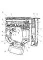
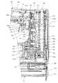
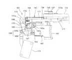
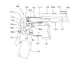
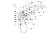
以下、本発明の実施形態につき、図1〜図5を参照しつつ詳細に説明する。本実施の形態は、打込み作業工具の一例として充電式ピンタッカを用いて説明する。図1は本実施の形態に係る充電式ピンタッカ100の全体構成を示す側断面図であり、図2は図1のA−A線に基づく断面図である。図3にはピンタッカ100の主要部の構成が拡大断面図として示される。図1に示すように、本実施の形態に係るピンタッカ100は、概括的に見て、ピンタッカ100の外殻を形成する本体部101と、バッテリが収容されるバッテリケース109と、被加工材に打ち込まれる打込み材としてのピンが装填されるマガジン111とを主体に構成される。 Hereinafter, embodiments of the present invention will be described in detail with reference to FIGS. The present embodiment will be described using a rechargeable pin tacker as an example of a driving work tool. FIG. 1 is a side sectional view showing an overall configuration of a
本体部101は、駆動モータ113を収容するモータハウジング103と、打込み機構117およびハンマ駆動機構119を収容するギアハウジング105と、作業者が握るハンドグリップ107とによって構成される。駆動モータ113は、本発明における「モータ」に対応し、ハンマ駆動機構119は、本発明における「作動機構」に対応する。モータハウジング103の上方にハンドグリップ107が配置され、それらモータハウジング103とハンドグリップ107の水平方向一端部(図1の右側)にギアハウジング105が配置され、水平方向他端部にバッテリケース109が配置される。モータハウジング103およびギアハウジング105の下方にマガジン111が配置される。なおマガジン111は、打ち込むべきピンを、ギアハウジング105の下端部、すなわち本体部101の先端部に連接されたピンの射出部112に供給するように構成される。 The
図3に示すように、打込み機構117は、上下方向に直線状に延在されて上端部および下端部がそれぞれギアハウジング105に固定された棒状のスライドガイド121と、スライドガイド121に筒状の滑り子123を介して上下動可能に装着されたハンマ125と、ハンマ125を下方に向って打込み動作させるべく当該ハンマ125に弾発力を作用させる手段としての圧縮コイルバネ127と、ハンマ125とともに移動されて射出部112のピン打込み口112aに供給されたピンに打撃力を加え、これによって当該ピンを被加工材に打込むドライバ129と、を主体にして構成されている。ドライバ129は、本発明における「打込み部材」に対応する。ハンマ125とドライバ129は、連結ピン131によって連結されている。またハンマ125は、ハンマ駆動機構119の上下のリフトローラ137,139と係合して上方へと押し上げられる上下の係合突起125a,125bを有する。なお便宜上ピンおよび被加工材については図示を省略する。 As shown in FIG. 3, the
駆動モータ113の回転出力は、遊星歯車式の減速機構115を介してハンマ駆動機構119に回転運動として伝達される。ハンマ駆動機構119は、図2および図3に示すように、互いに噛み合い係合して鉛直面内で互いに逆方向に回転する回転体としての上、下のギア133,135と、それらギア133,135の回転動作に伴い前記ハンマ125を上方へと押し上げる上下のリフトローラ137,139(図2参照)とを主体にして構成されている。 The rotational output of the
ギア133,135は、ギアハウジング105内に配置されたフレーム134に軸133a,135aを介して回転可能に装着されている。リフトローラ137,139は、ギア133,135の回転中心から偏心した位置に支持軸137a,139aを介して回転自在に装着され、ギア133,135の回転に伴いギア133,135中心回りを円運動、すなわち円弧状の運動をする。なお上部のリフトローラ137の支持軸137aからの偏心量と、下部のリフトローラ139の支持軸139aからの偏心量は、互いに等しく設定されている。下部のギア135は、減速機構115の出力軸115aに形成された駆動ギア115bに噛み合い係合されており、所定の減速比で回転駆動される。なお下部のギア135と上部のギア133は、ギア比が1対1に設定されている。また下部のリフトローラ139と上部のリフトローラ137は、約180度の位相差を有する配置とされている。そして上下のリフトローラ137,139は、互いに最も離間した位置、すなわち下部のリフトローラ139が下部のギア135の下側の位置に置かれ、上部のリフトローラ137が上部のギア133の上側に置かれた状態(図2に示す状態)を初期位置としている。 The
駆動モータ113が通電駆動され、上下のギア133,135が図2の矢印方向に回転されると、下部のリフトローラ139が下死点に置かれたハンマ125の下部の係合突起125bに下方から係合して上方へと円運動し、当該円運動のうちの上下方向成分によってハンマ125を上方へ押し上げる。下部のリフトローラ139によるハンマ125の押上げ量が最大付近に達した時点で、上部のリフトローラ137がハンマ125の上部の係合突起125aに下方から係合して上方へと円運動し、ハンマ125を上方へ押し上げる。かくして、ハンマ125は上下のリフトローラ137,139の中継を介して下死点(ピン打込み終了位置であって、初期位置に相当する)から上方、すなわち上死点側へと移動され、このハンマ125の上方への移動動作によって圧縮コイルバネ127が圧縮されて弾発力が蓄積される。そして上死点付近において、ハンマ125の上部の係合突起125aは、上部のリフトローラ137から更にカム140へと受け渡される。そしてハンマ125とともにドライバ129が上方へと引き上げられると、マガジン111に装填されているピンが射出部112のピン打込み口112aに供給され、その後、当該カム140との係合が解除されると同時に、ハンマ125は圧縮コイルバネ127の弾発力によって下方へ打込み動作される。これにより射出部112のピン打込み口112aに供給されたピンが当該ピン打込み口112a内を下降するドライバ129によって被加工材に打込まれる。打込み動作されたハンマ125は、ストッパ126に当接することで下死点に保持される。 When the
なおカム140とハンマ125との係合が解除されてから、ギア133,135は、次回のハンマ押し上げ動作に備えるべく、更に回転動作を継続し、上下のリフトローラ137,139が最も離間する初期位置に復帰して停止される。すなわち、下部のリフトローラ139が駆動され、ハンマ125に係合してドライバ129とともに当該ハンマ125の上方への押し上げ動作を開始してから下部のリフトローラ139が元の初期位置に戻り、次回のハンマ押し上げ動作に備えるまでの期間が本発明における「作業ストローク」に対応し、ギア133,135の各一回転に相当する。 After the engagement between the
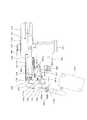
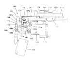
次に駆動モータ113の通電駆動と通電停止を操作する操作装置160につき、図4〜図32を参照しつつ詳細に説明する。先ず、操作装置160の構成につき図4、図5および図22に基づいて説明する。操作装置160は、使用者による引き操作によってオン状態に投入されるトリガスイッチ163と、当該トリガスイッチ163の引き操作に連動してオン状態に投入される内部スイッチ161と、オン状態に投入された内部スイッチ161のその後のオン状態あるいはオフ状態を制御するカムディスク177とを主体にして構成される。トリガスイッチ163は、本発明における「トリガスイッチ」に対応し、内部スイッチ161は、本発明における「内部スイッチ」に対応し、カムディスク177は、本発明における「制御部材」に対応する。 Next, the
トリガスイッチ163は、ハンドグリップ107に配置され、使用者によって直線状に引き操作されるトリガ141と、常時には駆動モータ113の通電駆動を禁止するオフ状態に付勢バネ(図示省略)によって付勢され、トリガ141の引き操作によって駆動モータ113の通電駆動を許容するオン状態に投入される第1スイッチ148(図1および図3参照)と、トリガ141の引き操作を内部スイッチ161に連動させるスイングアーム164とを主体にして構成される。トリガ141は、本発明における「指操作部材」に対応し、スイングアーム164は、本発明における「連動部材」に対応する。トリガ141は、フレーム134に固定状態で装着されたガイドプレート168に直線動作可能に装着されるとともに、圧縮コイルスプリング165によって引き操作方向と反対方向に付勢されており、常時には操作前の操作解除位置に保持されている。そしてトリガ141が引き操作されると、レバー163b(図3参照)を介して第1スイッチ148がオン状態に投入される。スイングアーム164は、支軸163aを介してトリガ141に連結され、トリガ141の引き操作方向と交差する方向に回動可能とされている。そしてスイングアーム164は、トリガ141の引き操作時には、後述する内部スイッチ161のカムブロック171と連動する連動位置(図5に示す位置)と、連動が解除される連動解除位置(図15に示す位置)との間で位置が切り換わる構成とされる。連動位置は、本発明における「動作位置」に対応し、連動解除位置は、本発明における「非動作位置」に対応する。 The
内部スイッチ161は、トリガ141の引き操作に連動して直線状に動作するカムブロック171と、カムブロック171によって回動動作されるスイッチアーム172と、常時には駆動モータ113の通電駆動を禁止するオフ状態に付勢バネ(図示省略)によって付勢され、スイッチアーム172の回動動作によって駆動モータの通電駆動を許容するオン状態に投入される第2スイッチ173とを主体にして構成される。カムブロック171は、本発明における「動作部材」に対応する。カムブロック171は、トリガ141の引き操作方向と同方向に直線状に移動し得るようにフレーム134に装着されている。カムブロック171は、連動位置に置かれたスイングアーム164と対向する係合部171aを有し、トリガ141が引き操作されたとき、当該トリガ141とともに引き操作方向へと移動するスイングアーム164の先端面164aに対して係合部171aが面接触で当接されるとともに、当該面接触状態を維持しつつ押圧移動される。すなわち、カムブロック171は、トリガ141の引き操作に連動して直線状に動作し、プッシュピン174を介してスイッチアーム172の一端を押し、これによりスイッチアーム172が支軸172a回りに回動動作して第2スイッチ173をオン状態に投入する構成とされる。なおスイッチアーム172は、第2スイッチ173のオン状態を解除する側に第1トーションスプリング175によって付勢されている。 The
またスイングアーム164には、第2トーションスプリング166が設けられ(図31および図32参照)、トリガ141には、第3トーションスプリング167が設けられている。第2トーションスプリング166は、本発明における「弾性部材」および「第2のバネ部材」に対応し、第3トーションスプリング167は、本発明における「第1のバネ部材」に対応する。第2トーションスプリング166は、一方の足166aがスイングアーム164に係止され、他方の足166bが自由状態となっており、当該自由側の足166bを支軸163a回りに回動動作させたとき、当該第2トーションスプリング166を介してスイングアーム164が回動される構成とされる。なお2トーションスプリング166の自由側の足166bは、その先端部が約90度折り曲げられている。第3トーションスプリング167は、一方の足167aがトリガ141に係止され、他方の足167bが第2トーションスプリング166の自由側の足166b(折り曲げ部)に係止されている。これにより、第3トーションスプリング167の付勢力は、常時に第2トーションスプリング166を介してスイングアーム164を連動位置から連動解除位置へと回動させる方向に付与され、この付勢力は前述したガイドプレート168によって受けられる。 The
ガイドプレート168は、第2トーションスプリング166の自由側の足166bと係合するガイド面169を有する。ガイド面169は、トリガ141の操作方向、すなわちカムブロック171の動作方向と平行な方向に延びる平面部169aと、当該平面部169aに交差状に連続して延びる斜面部169bとからなり、トリガ141が操作解除位置に置かれた状態では、第2トーションスプリング166の自由側の足166bを平面部169aによって受け、これによりスイングアーム164を連動位置に保持する構成とされている。上記のガイドプレート168は、本発明における「ガイド部材」に対応する。トリガ141が引き操作されると、トリガ141とともに移動するスイングアーム164の先端面164aがカムブロック171の係合部171aに面接触で当接して当該スイングアーム164が第2スイッチ173をオン状態とする投入方向へと押圧移動されるが、この移動に伴い第2トーションスプリング166の自由側の足166bがガイド面169の平面部169aを通過し、斜面部169b側へと移動する。このとき、スイングアーム164は、面接触される当接面の摩擦力によって第3トーションスプリング167の付勢力に抗して連動位置に維持される。このため、第2トーションスプリング166の自由側の足166bは、斜面部169bから離間した位置(空間)に置かれるが(図9参照)、その後、カムブロック171が後述するカムディスク177によって第2スイッチ173をオン状態とする投入方向(トリガ引き方向)へと更に移動され、当該カムブロック171に対するスイングアーム164の当接状態が解除されたときに、第3トーションスプリング167の付勢力によってスイングアーム164が連動位置から連動解除位置へと回動される構成とされている(図15参照)。 The
連動解除位置へ回動されたスイングアーム164は、トリガ141の引き操作が解除されることに伴い、当該トリガ141が操作解除位置へ戻る際、カムブロック171がトリガ141よりも先に初期位置に戻っていた場合には、当該カムブロック171の下面を通り抜けてから初期位置、つまり連動位置に復帰される。このことについては後述する。 The
以上のように、本実施の形態に係る操作装置160は、トリガ141が引き操作されたときは、スイングアーム164を介してカムブロック171が連動し、これによってトリガ141によって第1スイッチ148がオン状態に投入され、と同時にカムブロック171、プッシュピン174、スイッチアーム172を介して第2スイッチ173がオン状態に投入される構成とされる。そして第1スイッチ148と第2スイッチ173がそれぞれオン状態とされたときに通電駆動され、第1スイッチ148または第2スイッチ173のいずれか一方がオフ状態となったときに通電が停止される構成とされる。なお図1および図3においては、第1スイッチ148と第2スイッチ173とは互いに重なり合うように配置される。このため、図1および図3では、第2スイッチ173については図示が省略される。 As described above, in the
次にカムブロック171を制御するカムディスク177につき、主として図4および図22を参照しつつ説明する。カムディスク177は、前述したハンマ駆動機構119における上部のギア133と一体に回転するように装着されている(図3参照)。カムディスク177は、その円周面がカム面178として設定され、カムブロック171の先端が当該カム面178に対向するように配置されている。カムディスク177のカム面178は、周方向において、トリガ141の引き操作に連動して第2スイッチ173をオン状態にする投入方向へと移動されたカムブロック171の先端と係合し、当該カムブロック171を投入方向へと更に移動させることによりカムブロック171とスイングアーム164との連動を解除する掬い傾斜領域178aと、カムブロック171の先端との係合を維持しつつ相対移動することによって第2スイッチ173のオン状態を維持する大径領域178bと、カムブロック171の先端との係合を解除し、第2スイッチ173のオフ状態への復帰を許容する小径領域178cと、を有する。掬い傾斜領域178aは、本発明における「連動解除領域」に対応し、大径領域178bは、本発明における「オン状態継続領域」に対応し、小径領域178cは、本発明における「オフ状態復帰領域」に対応する。 Next, the
なお掬い傾斜領域178aによってカムブロック171が投入方向へと更に移動されたときの、スイッチアーム172の過剰な動き回避するべく、カムブロック171とスイッチアーム172との間に介在されるプッシュピン174は、当該カムブロック171に対して投入方向と同方向に相対移動可能とされるとともに、付勢バネ174aの弾発力を介してスイッチアーム172に当接されている。すなわち、掬い傾斜領域178aによるカムブロック171の投入方向への移動時には、プッシュピン174がカムブロック171に対して相対移動することで当該カムブロック171の動きを吸収する。 A
掬い傾斜領域178aは、大径領域178bと小径領域178cとの間に位置し、小径領域178cから大径領域178bに向って直線状に延びる斜面によって形成される。大径領域178bと小径領域178cのそれぞれは、カムディスク171の回転軸心を中心とする円弧面によって形成されている。またカムディスク177は、小径領域178cと掬い傾斜領域178aとの境界にストッパ面178dを有し、当該ストッパ面178dがカムブロック171の先端側面に当接することによって当該カムディスク177の規定位置を越える回転(オーバーラン)が規制されている。そしてカムディスク177は、カムブロック171の先端が小径領域178cの掬い傾斜領域178a側端部に置かれた位置、すなわちストッパ面178dに当接あるいは近接した位置を初期位置して定められており、回転動作時において、カムブロック171に対して掬い傾斜領域178a、大径領域178b、小径領域178cの順で対向するよう構成されている。 The scooping inclined
なお本実施の形態においては、図4に示すように、小径領域178cは、カムディスク177の円周のうちの90度を越える範囲を占めている。これは、第2スイッチ173のオフ状態への復帰に伴う駆動モータ113に対する通電停止後において、当該駆動モータ113にブレーキを作動させるブレーキ作動領域として活用するべく設定されている。すなわち、小径領域178cは、ブレーキ作動領域を備えた構成とされる。 In the present embodiment, as shown in FIG. 4, the small-
また本実施の形態においては、トリガ141の引き操作を禁止するセーフティレバー143をハンドグリップ107に備えている。トリガ141は、セーフティレバー143が図1に実線で示されるロック位置に置かれるときは、引き操作が不能とされ、セーフティレバー143が図1に仮想線で示すロック解除位置に置かれたときに引き操作が可能とされる。また本体部101には、ピンの打込み領域を照射するライト145(図1参照)が設けられている。ライト145は、セーフティレバー143がロック解除位置に置かれたときに、当該セーフティレバー143によってライト点灯用のスイッチ147がオン動作されることで点灯され、セーフティレバー143がロック位置に置かれたときに、ライト点灯用のスイッチ147がオフ動作されることで消灯されるように構成されている。 In the present embodiment, the
本実施の形態に係るピンタッカ100は、上記のように構成されている。以下、図4〜図30を参照しつつ、ピンタッカ100の作用につき操作装置160を主体にして説明する。図4、図5および図22は、操作装置160が使用者によって操作されていない初期状態を示している。この初期状態では、スイングアーム164が連動位置に置かれ、その先端面164aがカムブロック171の係合部171aに対して所定の間隔を置いて対向している。またカムブロック171の先端がカムディスク177の小径領域178cの端部付近に位置している。そして第1スイッチ148および第2スイッチ173がともにオフ状態に置かれ、駆動モータ113が停止している。またドライバ129が下死点に置かれている(図2参照)。 The
図6、図7および図23には、使用者によるトリガ141の引き操作が開始された状態が示され、スイングアーム164の先端面164aがカムブロック171の係合部171aに面接触で当接されている。図8、図9および図24には、トリガ141が更に引かれ、トリガ141とともに移動するスイングアーム164によってカムブロック171が押されて移動した状態が示される。すなわち、カムブロック171は、カムディスク177のストッパ面178dから外れた位置(当接回避位置)まで移動され、カムディスク177の回転を許容する。このとき、第1および第2スイッチ148,173がオン動作される直前の状態である。またスイングアーム164に設けられた第2トーションスプリング166の自由側の足166bがガイド面169の平面部169aを通過するが、スイングアーム164は、カムブロック171の係合部171aとの当接面の摩擦力によって第3トーションスプリング167の付勢力に抗して連動位置に保持される。 6, 7, and 23 show a state in which the user has started pulling the
図10、図11および図25には、トリガ141が更に引かれ、レバー163bを介し第1スイッチ148がオン状態に投入され、と同時にカムブロック171、プッシュピン174、スイッチアーム172を介して第2スイッチ173がオン状態に投入され、これにより駆動モータ113が通電駆動された状態が示される。駆動モータ113が通電駆動されると、前述したように、減速機構115を介してハンマ駆動機構119のギア133,135が駆動され、ハンマ125の押し上げ動作が開始される。すなわちドライバ129のピン打込み作業がスタートする。一方、ギア133,135が駆動されることに伴いカムディスク177が図示の左回りに回転を開始し、掬い傾斜領域178aによってカムブロック171を投入方向へと移動させる。 10, 11 and 25, the
図12、図13および図26には、トリガ141が更に引かれて引き操作端に達するとともに、カムブロック171がカムディスク177の掬い傾斜領域178aによって投入方向へ更に移動された状態が示される。トリガが引き操作端に達してから、カムブロック171はカムディスク177の掬い傾斜領域178aによって投入方向へ更に移動される。これにより、カムブロック171の係合部171aがスイングアーム164の先端面164aから離間し、当接面間における摩擦力が消去する。このため、スイングアーム164は、第3トーションスプリング167の付勢力により、連動位置から連動解除位置へと回動される。この状態が図14、図15および図27に示される。 FIGS. 12, 13 and 26 show a state in which the
カムディスク177は、回転を続け、カムブロック171の先端が当該カムディスク177の大径領域178bに乗り上がる。これにより第2スイッチ173のオン状態が維持され、またトリガ141の引き操作によってオン状態に投入されている第1スイッチ148もオン状態が維持されるため、駆動モータ113の通電駆動も維持される。この状態が図16、図17および図28に示される。そしてカムブロック171の先端がカムディスク177の大径領域178bに係合しつつ相対移動する過程において、ドライバ129によるピンの打込み動作が行われる。すなわち、ハンマ駆動機構119のリフトローラ137,139およびカム140を介して上死点へと移動されたハンマ125が、当該カム140との係合を解除される。そして係合を解除されたハンマ125とともにドライバ129が、蓄積された圧縮コイルバネ127の弾発力によって下方へ打込み動作され、ピンを被加工材に打込む。なお打込み動作されたハンマ125は、ストッパ126に当接することで下死点に保持される。 The
カムディスク177は、更に回転を続け、カムブロック171の先端が当該カムディスク177の小径領域178cに達する。すると、第1トーションスプリング175の付勢力により、スイッチアーム172、プッシュピン174を介してカムブロック171がトリガ141の引き方向と逆方向へ移動される。これにより、第2スイッチ173がオフ状態に復帰され、駆動モータ113に対する通電が停止される。この状態が図18、図19および図29に示される。その後、駆動モータ113は制動を受けつつ、慣性によって回転を続けた後停止する。これにより、カムディスク177も同様に回転し、小径領域178cの端部付近の初期位置に戻り、またハンマ駆動機構119の各構成部材もそれぞれ初期位置に戻る。 The
使用者がトリガ141から手を離して引き操作を解除すると、トリガ141は、圧縮コイルスプリング165の付勢力により、引き操作前の操作解除位置に戻る。このとき、トリガ141とともにスイングアーム164が移動することに伴い、第2トーションスプリング166の自由側の足166bがガイド面169の斜面部169bに当接して押され、スイングアーム164は、元の位置、すなわち連動位置に戻ろうとする。この状態が図20、図21および図30に示される。このとき、スイングアーム164は、カムブロック171の係合部171aの下面に接触するが、ガイドプレート168の斜面部169bにて案内される第2トーションスプリング166が撓むことによって係合部171aの下面に接触しつつ通り抜け、図4、図5および図22に示す初期位置である連動位置へと復帰される。なお第2トーションスプリング166は、ガイドプレート168の斜面部169bにて案内されて移動するときそれ自体が撓みつつ第3トーションスプリング167を撓ませて初期位置に復帰させる。これにより第3トーションスプリング167には、スイングアーム164を連動位置から連動解除位置へと回動させる付勢力が付与(補充)されることになる。かくして、ドライバ129によるピンの一回の打込み作業が完了する。 When the user releases the
なお使用者がトリガ141の引き操作を、例えばドライバ129を下死点から上死点へ押し上げる段階等の、ドライバ129による打込み作業の途中で中断することが考えられる。このとき、本実施の形態の操作装置160によれば、内部スイッチ161系の第2スイッチ173はカムディスク177によってオン状態に維持されるも、トリガスイッチ163系の第1スイッチ148がトリガ141の操作解除位置への復帰に伴いオフ状態に戻る。このため、駆動モータ113に対する通電が停止され、打込み作業を途中で止めることができる。また中断後において、トリガ141を再び引き操作して第1スイッチ148をオン状態に投入すれば、駆動モータ113が通電駆動される。すなわち、中断したドライバ129による打ち込み作業を支障なく再開することができる。 Note that it is conceivable that the user interrupts the pulling operation of the
以上述べたように、本実施の形態に係る操作装置160は、トリガ141が引き操作されたとき、第1スイッチ148がオン状態に投入されるとともに、第2スイッチ173がトリガ141の引き操作に連動してオン状態に投入されて維持され、そしてトリガ141の引き操作の解除によって当該第1スイッチ148がオフ状態に戻される第1の操作モードを有する。この第1の操作モードは、本発明における「第1モード」に対応する。
またトリガ141の引き操作が維持されると、第1スイッチ148のオン状態が維持されるとともに、第2スイッチ173が作業ストロークの所定期間にわたってオン状態が維持されてからオフ状態へと復帰され、そしてトリガ141の引き操作の解除によって第1スイッチ148がオフ状態に戻される第2の操作モードを有する。この第2の操作モードは、本発明における「第2モード」に対応する。そしてトリガ141の引き操作による操作装置160の第1の操作モードへの投入によって打込み部材の作業ストロークが開始し、当該作業ストロークの開始後の所定時期に第1の操作モードから第2の操作モードに切り換わる構成である。As described above, in the
When the pulling operation of the
上記のように構成された本実施の形態によれば、トリガ141を一回引き操作する毎にドライバ129に一回の打込み作業を行わせてから停止させるといった動作を、トリガ141の引き操作のみで行うことができる。このため、接触検出アームの被加工材に対する押し当て操作とトリガの引き操作とを必要とする従来装置に比べて、操作装置160の操作性を向上することができる。 According to the present embodiment configured as described above, every time the
また本実施の形態においては、トリガ141の引き操作方向とカムブロック171の動作方向とを同方向に定めている。このことにより、当該トリガ141の引き操作に対するカムブロック171の連動システムを構築する際の設計が楽になる。またトリガ141とカムブロック171との連動あるいは連動解除を、回動動作するスイングアーム164によって行う構成である。このため、スイングアーム164は、軸と孔との嵌め合いによる構成となり、加工精度が出し易く、円滑な動作を得ることができる。またスイングアーム164が連動解除位置から連動位置へ復帰する際の動作につき、第2トーションスプリング166の撓みを利用することによってスイングアーム164をカムブロック171に干渉させつつ合理的に連動位置へと復帰することを可能としている。 In the present embodiment, the pulling operation direction of the
また本実施の形態においては、トリガ141の引き操作に連動して第2スイッチ173をオン状態に投入動作するカムブロック171につき、回転動作するカムディスク177によって制御するとともに、当該カムディスク177を、ハンマ119を駆動するハンマ駆動機構119のギア133と一体に回転する構成としている。このため、ハンマ駆動機構119によるハンマ125の駆動動作に対するカムブロック171による、第2スイッチ173のオン動作あるいはオフ動作の動作タイミングが設定し易い。また第2スイッチ148のオフ動作のタイミング、つまり駆動モータ113に対する通電を停止するタイミングを、当該駆動モータ113のブレーキ作動後の停止位置を考慮して設定することが可能となる。本実施の形態では、カムディスク177に形成される小径領域178cに駆動モータ113に対するブレーキ作動領域を備えた構成であり、これにより駆動モータ113の通電の停止後における当該駆動モータ113およびハンマ駆動機構119を衝撃の少ない状態で停止することが可能とされる Further, in the present embodiment, the
なお本実施の形態では、スイングアーム164が連動位置と連動解除位置との間で回動動作するによって、トリガ141とカムブロック171とを連動あるいは連動を解除する構成としたが、スイングアーム164に代えてトリガ141の引き操作方向と交差する方向に直線状に移動する摺動部材を設け、当該摺動部材を連動位置と連動解除位置との間で移動することによってトリガ141とカムブロック171とを連動あるいは連動を解除する構成としてもよい。また本実施の形態は、ピンタッカ100を用いて説明したが、これに限らず、圧縮コイルバネ127の弾発力によってハンマ125の打込み動作を行う形式の打込み作業工具であれば、適用することが可能である。また圧縮コイルバネ127は、引っ張りコイルバネに変更してもよい。 In this embodiment, the
上記発明の趣旨に鑑み、以下の態様を構成することが可能とされる。
(態様1)
「請求項1〜3のいずれかに記載の打込み作業工具であって、
前記連動部材は、前記指操作部材の引き操作方向と交差する方向に回動動作し、これによって前記内部スイッチと連動する動作位置と、当該連動が解除される非動作位置との間で位置が切り換わる構成としたことを特徴とする打込み作業工具。」In view of the gist of the invention, the following aspects can be configured.
(Aspect 1)
"A driving work tool according to any one of claims 1 to3 ,
The interlocking member rotates in a direction intersecting with the pulling operation direction of the finger operation member, whereby the position is between an operation position interlocked with the internal switch and a non-operation position where the interlock is released. A driving work tool characterized by being configured to switch. "
(態様2)
「態様1に記載の打込み作業工具であって、
前記連動部材は、前記指操作部材が引き操作される際、当該引き操作方向において前記内部スイッチと面接触で当接するとともに当該当接面の摩擦力によって前記内部スイッチと連動する動作位置に保持され、前記内部スイッチから離間して前記摩擦力が消去したときには、弾性部材による弾性力によって非動作位置へ回動動作される構成としたことを特徴とする打込み作業工具。」(Aspect 2)
“A driving work tool according to aspect 1,
When the finger operation member is pulled, the interlocking member comes into contact with the internal switch in surface contact in the pulling operation direction and is held at an operating position interlocked with the internal switch by the frictional force of the contact surface. A driving tool that is configured to rotate to a non-operating position by an elastic force of an elastic member when the frictional force is erased away from the internal switch. "
(態様3)
「態様1または2に記載の打込み作業工具であって、
前記連動部材は、前記指操作部材が引き操作方向と反対方向へ動作する際、前記弾性部材を撓ませつつ前記内部スイッチに対して相対的に滑り移動することで、前記非動作位置から前記動作位置に復帰する構成としたことを特徴とする打込み作業工具。」(Aspect 3)
“A driving work tool according to aspect 1 or 2,
When the finger operating member moves in the direction opposite to the pulling operation direction, the interlocking member slides relative to the internal switch while bending the elastic member, thereby moving the operation from the non-operating position. A driving work tool characterized by being configured to return to a position. "
100 ピンタッカ(打込み作業工具)
101 本体部
103 モータハウジング
105 ギアハウジング
107 ハンドグリップ
109 バッテリケース
111 マガジン
112 射出部
112a ピン打込み口
113 駆動モータ(モータ)
115 減速機構
115a 出力軸
115b 駆動ギア
117 打込み機構
119 ハンマ駆動機構(作動機構)
121 スライドガイド
123 滑り子
125 ハンマ
125a 上部の係合突起
125b 下部の係合突起
126 ストッパ
127 圧縮コイルバネ
129 ドライバ(打込み部材)
131 連結ピン
133 上部のギア
133a 軸
134 フレーム
135 下部のギア
135a 軸
137 上部のリフトローラ
137a 支持軸
139 下部のリフトローラ
139a 支持軸
140 カム
141 トリガ
143 セーフティレバー
145 ライト
147 ライト点灯用のスイッチ
148 第1スイッチ
160 操作装置
161 内部スイッチ
163 トリガスイッチ
163a 支軸
163b レバー
164 スイングアーム(連動部材)
164a 先端面
165 圧縮コイルスプリング
166 第2トーションスプリング(弾性部材、第2のバネ部材)
166a 一方の足
166b 他方の(自由側の)足
167 第3トーションスプリング(第1のバネ部材)
167a 一方の足
167b 他方の(自由側の)足
168 ガイドプレート(ガイド部材)
169 ガイド面
169a 平面部
169b 斜面部
171 カムブロック
171a 係合部
172 スイッチアーム
172a 支軸
173 第2スイッチ
174 プッシュピン
174a 付勢バネ
175 第1トーションスプリング
177 カムディスク(制御部材)
178 カム面
178a 掬い傾斜領域(連動解除領域)
178b 大径領域(オン状態継続領域)
178c 小径領域(オフ状態復帰領域)
178d ストッパ面
100 pin tacker (driving work tool)
DESCRIPTION OF
115 Deceleration mechanism 115a
121
131
164a
166a One foot 166b The other (free side)
167a One
169 Guide surface
178
178b Large diameter region (on-state continuation region)
178c Small diameter area (off state return area)
178d Stopper surface
Claims (5)
Translated fromJapanese前記打込み部材に打込み作業を行わせるべく当該打込み部材を駆動する作動機構と、
前記作動機構を駆動するモータと、
前記モータの通電駆動と通電停止を操作する操作装置と、を有し、
前記打込み部材が一の打込み材の打込み動作を開始してから次の打込み材の打込み準備を完了するまでの期間を当該打込み部材の作業ストロークとする打込み作業工具であって、
前記操作装置は、
常時には前記モータの通電駆動を禁止するオフ状態に付勢され、使用者によって引き操作されることで前記モータの通電駆動を許容するオン状態に投入されるトリガスイッチと、
常時には前記モータの通電駆動を禁止するオフ状態に付勢され、前記トリガスイッチの引き操作に連動して前記モータの通電駆動を許容するオン状態に投入されるとともに、当該オン状態が前記作業ストローク中の所定期間にわたって維持されてからオフ状態へと復帰する内部スイッチと、を有し、
前記トリガスイッチと前記内部スイッチの両方がそれぞれオン状態に投入されることで前記モータが通電駆動され、いずれか一方がオフ状態に戻されたときには前記モータに対する通電が停止するように構成され、
更に前記操作装置は、前記トリガスイッチの引き操作によって当該トリガスイッチがオン状態に投入されるとともに、前記内部スイッチが前記トリガスイッチの引き操作に連動してオン状態に投入されて維持され、前記トリガスイッチの引き操作の解除によって当該トリガスイッチがオフ状態に戻される第1モードと、
前記トリガスイッチの引き操作の維持によって当該トリガスイッチのオン状態が維持されるとともに、前記内部スイッチが前記トリガスイッチとの連動を解除されるとともに前記作業ストロークの所定期間にわたってオン状態が維持されてからオフ状態へと復帰され、前記トリガスイッチの引き操作の解除によって当該トリガスイッチがオフ状態に戻される第2モードと、を有し、
前記トリガスイッチの引き操作による前記操作装置の前記第1モードへの投入によって前記打込み部材の作業ストロークが開始し、当該作業ストロークの開始後の所定時期に前記第1モードから前記第2モードに切り換わるように構成されており、
前記トリガスイッチの操作方向と、前記内部スイッチのオン状態への投入方向が同じ方向に定められており、
前記トリガスイッチは、使用者により操作方向へと引き操作される指操作部材と、前記指操作部材に連結されるとともに、操作方向に向って前記内部スイッチと連動して動く動作位置と、前記内部スイッチと連動しない非動作位置との間で切換可能とされた連動部材と、を有し、
前記連動部材は、常時には前記非動作位置に付勢されるとともに、前記第1モードにおいては、前記内部スイッチと当接することで前記付勢に抗して前記動作位置に保持され、前記第1モードから前記第2モードに切り換わる際、前記内部スイッチの投入方向への更なる動きに伴って前記当接が解除されることで前記動作位置から前記非動作位置に切り換わり、これにより前記内部スイッチとの連動が解除されることを特徴とする打込み作業工具。A driving member that linearly moves to perform driving work of the driving material;
An actuating mechanism for driving the driving member to cause the driving member to perform a driving operation;
A motor for driving the operating mechanism;
An operation device for operating energization driving and energization stop of the motor,
A driving work tool in which a period from when the driving member starts driving operation of one driving material to completion of driving preparation of the next driving material is set as a working stroke of the driving member,
The operating device is:
A trigger switch that is normally energized to an off state that prohibits energization driving of the motor and is turned on to allow energization driving of the motor by being pulled by a user;
Normally, the motor is energized to an off state that prohibits energization driving of the motor, and is turned on to allow energization driving of the motor in conjunction with the pulling operation of the trigger switch. An internal switch that is maintained for a predetermined period of time and then returns to an off state,
The motor is energized and driven when both the trigger switch and the internal switch are turned on, and the power to the motor is stopped when either one is returned to the off state.
Further, the operation device is configured such that the trigger switch is turned on by the pulling operation of the trigger switch, and the internal switch is turned on and maintained in conjunction with the pulling operation of the trigger switch. A first mode in which the trigger switch is returned to an off state by release of the pulling operation of the switch;
The trigger switch is kept on by maintaining the pulling operation of the trigger switch, and the internal switch is released from the interlock with the trigger switch and is kept on for a predetermined period of the work stroke. A second mode in which the trigger switch is returned to the off state and the trigger switch is returned to the off state by releasing the pulling operation of the trigger switch;
The operating stroke of the driving member is started by turning the operating device into the first mode by pulling the trigger switch, and the first mode is switched to the second mode at a predetermined time after the start of the operating stroke.Configured to replace,
The operation direction of the trigger switch and the input direction to the ON state of the internal switch are determined in the same direction,
The trigger switch includes a finger operation member that is pulled in an operation direction by a user, an operation position that is coupled to the finger operation member and moves in conjunction with the internal switch in the operation direction, An interlocking member that is switchable between a non-operating position that is not interlocked with the switch,
The interlocking member is always urged to the non-operating position, and in the first mode, the interlocking member is held at the operating position against the urging by contacting the internal switch. When the mode is switched to the second mode, the contact is released in accordance with the further movement of the internal switch in the closing direction, thereby switching from the operating position to the non-operating position. Driving tool characterizedin that the interlock with the switch is released .
前記指操作部材の引き操作が解除されることに伴い当該指操作部材が引き操作前位置へと復帰されるとき、前記連動部材を前記非動作位置から前記動作位置に切り換えるべく案内するガイド部材を有し、
前記連動部材は、その一部が弾性変形可能な弾性部材で構成され、
前記第2モードの終了に伴い前記内部スイッチが前記オン状態からオフ状態へと復帰された状態において、前記指操作部材の引き操作が解除され、当該指操作部材が引き操作前位置へと復帰されることに伴い前記連動部材がガイド部材によって前記非動作位置から前記動作位置に案内されるとき、前記連動部材は、前記内部スイッチに干渉することに伴い当該内部スイッチに対して前記弾性部材を介して弾発状に変位ないし変形し、これによって前記干渉による切り換わり動作を阻害されることなく前記非動作位置から前記動作位置への切り換わりが許容される構成としたことを特徴とする打込み作業工具。The driving tool according to claim1 ,
A guide member for guiding the interlocking member to switch from the non-operating position to the operating position when the finger operating member is returned to the position before the pulling operation as the pulling operation of the finger operating member is released; Have
The interlocking member is composed of an elastic member that is partly elastically deformable,
When the internal switch is returned from the on state to the off state upon completion of the second mode, the pull operation of the finger operation member is released and the finger operation member is returned to the position before the pull operation. When the interlocking member is guided from the non-operating position to the operating position by the guide member, the interlocking member interferes with the internal switch through the elastic member. The driving operation is characterized in that the switching operation is allowed to change from the non-operation position to the operation position without hindering the switching operation due to the interference. tool.
前記連動部材を前記非動作位置に付勢する手段は、第1のバネ部材によって構成され、
前記弾性部材は、第2のバネ部材によって構成され、
前記第1のバネ部材と前記第2のバネ部材とは、それぞれの付勢力が互いに作用し合うように係合され、
前記第1のバネ部材の付勢力によって前記連動部材が前記動作位置から前記非動作位置に切り換わる場合、前記第2のバネ部材は、前記第1の付勢力を前記連動部材に対して当該連動部材を前記動作位置から前記非動作位置へと動作させる力として伝達する伝達要素として機能し、
前記連動部材が前記非動作位置から前記動作位置へと切り換わる場合、前記第1のバネ部材は、前記ガイド部材によって前記非動作位置から前記動作位置へと案内される際、前記第2のバネ部材によって初期位置に復帰されることを特徴とする打込み作業工具。A driving tool according to claim2 ,
The means for biasing the interlocking member to the non-operation position is constituted by a first spring member,
The elastic member is constituted by a second spring member,
The first spring member and the second spring member are engaged so that respective biasing forces act on each other,
When the interlocking member is switched from the operating position to the non-operating position by the biasing force of the first spring member, the second spring member applies the first biasing force to the interlocking member. Functions as a transmission element that transmits a member as a force for operating the member from the operating position to the non-operating position;
When the interlocking member switches from the non-operating position to the operating position, the first spring member is guided by the guide member from the non-operating position to the operating position. A driving tool which is returned to an initial position by a member.
前記内部スイッチは、前記トリガスイッチの引き操作に連動して前記内部スイッチがオン状態となる投入方向へと移動する動作部材と、前記モータによって動作されるとともに、前記第1モードから第2モードに切り換わる際および切り換わり後の前記動作部材の動作を制御する制御部材と、を有し、
前記制御部材は、
前記動作部材と係合して相対移動することによって前記トリガスイッチの引き操作により投入方向へと移動された前記動作部材を更に投入方向へと動作させ、これにより前記内部スイッチのオン状態を維持しつつ前記動作部材の前記トリガスイッチとの連動を解除する連動解除領域と、
前記連動解除領域に連続し、前記動作部材と係合して更に相対移動することによって連動解除後における前記内部スイッチのオン状態を継続するオン状態継続領域と、
前記オン状態継続領域に連続し、前記動作部材との係合を解除することによって当該動作部材の前記投入方向と反対方向への移動を許容し、これにより前記内部スイッチのオフ状態への復帰を許容するオフ状態復帰領域と、を有することを特徴とする打込み作業工具。The driving tool according to any one of claims 1 to3 ,
The internal switch is operated by the motor and an operation member that moves in the closing direction in which the internal switch is turned on in conjunction with the pulling operation of the trigger switch, and is changed from the first mode to the second mode. A control member for controlling the operation of the operation member when switching and after switching,
The control member is
By engaging and moving relative to the operating member, the operating member moved in the closing direction by the pulling operation of the trigger switch is further operated in the closing direction, thereby maintaining the on state of the internal switch. While the interlock release region to cancel the interlock with the trigger switch of the operating member,
An on-state continuation region that continues to the on-state of the internal switch after disengagement by engaging with the operation member and further moving relative to the interlock release region;
The movement of the operation member in the direction opposite to the closing direction is permitted by releasing the engagement with the operation member continuously from the on-state continuation region, thereby returning the internal switch to the off state. A driving work tool characterized by having an off-state return region to be allowed.
前記制御部材のオフ状態復帰領域に、前記内部スイッチのオフ状態への復帰に伴う前記モータの通電停止後における、当該モータのブレーキ作動を可能とするブレーキ作動領域を備えたことを特徴とする打込み作業工具。A driving work tool according to claim4 ,
The drive member is provided with a brake operation region that enables a brake operation of the motor after the energization stop of the motor accompanying the return of the internal switch to the OFF state in the OFF state return region of the control member. Work tools.
Priority Applications (5)
| Application Number | Priority Date | Filing Date | Title |
|---|---|---|---|
| JP2005305091AJP4749828B2 (en) | 2005-10-19 | 2005-10-19 | Driving tool |
| CNB2006101042628ACN100506492C (en) | 2005-10-19 | 2006-08-07 | punch in tool |
| TW095133718ATW200716330A (en) | 2005-10-19 | 2006-09-12 | Power tool for punching operation |
| US11/544,710US7513402B2 (en) | 2005-10-19 | 2006-10-10 | Power tool |
| EP06021222AEP1777040B1 (en) | 2005-10-19 | 2006-10-10 | Power tool |
Applications Claiming Priority (1)
| Application Number | Priority Date | Filing Date | Title |
|---|---|---|---|
| JP2005305091AJP4749828B2 (en) | 2005-10-19 | 2005-10-19 | Driving tool |
Publications (2)
| Publication Number | Publication Date |
|---|---|
| JP2007111819A JP2007111819A (en) | 2007-05-10 |
| JP4749828B2true JP4749828B2 (en) | 2011-08-17 |
Family
ID=38058292
Family Applications (1)
| Application Number | Title | Priority Date | Filing Date |
|---|---|---|---|
| JP2005305091AExpired - LifetimeJP4749828B2 (en) | 2005-10-19 | 2005-10-19 | Driving tool |
Country Status (3)
| Country | Link |
|---|---|
| JP (1) | JP4749828B2 (en) |
| CN (1) | CN100506492C (en) |
| TW (1) | TW200716330A (en) |
Cited By (1)
| Publication number | Priority date | Publication date | Assignee | Title |
|---|---|---|---|---|
| DE102021124712A1 (en) | 2020-09-30 | 2022-03-31 | Makita Corporation | DRIVE TOOL |
Families Citing this family (6)
| Publication number | Priority date | Publication date | Assignee | Title |
|---|---|---|---|---|
| JP5073380B2 (en)* | 2007-06-28 | 2012-11-14 | 株式会社マキタ | Electric driving tool |
| JP5133000B2 (en)* | 2007-06-28 | 2013-01-30 | 株式会社マキタ | Electric driving tool |
| JP5026233B2 (en)* | 2007-11-19 | 2012-09-12 | 株式会社マキタ | Magazine of driving machine |
| DE102011089860A1 (en)* | 2011-12-23 | 2013-06-27 | Hilti Aktiengesellschaft | driving- |
| JP6824781B2 (en)* | 2017-03-01 | 2021-02-03 | 株式会社マキタ | Driving tool |
| CN110757418B (en)* | 2018-07-27 | 2024-12-10 | 宝时得机械(张家港)有限公司 | Power Tools |
Family Cites Families (9)
| Publication number | Priority date | Publication date | Assignee | Title |
|---|---|---|---|---|
| JPS60135182A (en)* | 1983-12-23 | 1985-07-18 | 松下電工株式会社 | Electric cutter |
| US4834278A (en)* | 1988-06-13 | 1989-05-30 | Lin Chung Cheng | Structure of dc motorized nailing machine |
| JPH07100306B2 (en)* | 1990-04-18 | 1995-11-01 | 株式会社マキタ | Electric tucker |
| JPH07115307B2 (en) | 1989-04-24 | 1995-12-13 | 株式会社マキタ | Electric tucker |
| US4953774A (en)* | 1989-04-26 | 1990-09-04 | Regitar Power Tools Co., Ltd. | Electric stapling gun with auto-reset, energy-saving and shock-absorbing functions |
| JP2910088B2 (en)* | 1989-09-25 | 1999-06-23 | ソニー株式会社 | Semiconductor device |
| JP2568736Y2 (en)* | 1993-12-06 | 1998-04-15 | マックス株式会社 | Portable electric staple driving machine |
| AU2002323786A1 (en)* | 2002-07-25 | 2004-02-16 | Yih Kai Enterprise Co., Ltd. | A hand-held nailing tool |
| JP4509662B2 (en)* | 2004-06-16 | 2010-07-21 | 株式会社マキタ | Electric impact tool |
- 2005
- 2005-10-19JPJP2005305091Apatent/JP4749828B2/ennot_activeExpired - Lifetime
- 2006
- 2006-08-07CNCNB2006101042628Apatent/CN100506492C/enactiveActive
- 2006-09-12TWTW095133718Apatent/TW200716330A/enunknown
Cited By (2)
| Publication number | Priority date | Publication date | Assignee | Title |
|---|---|---|---|---|
| DE102021124712A1 (en) | 2020-09-30 | 2022-03-31 | Makita Corporation | DRIVE TOOL |
| US11667020B2 (en) | 2020-09-30 | 2023-06-06 | Makita Corporation | Driving tool |
Also Published As
| Publication number | Publication date |
|---|---|
| JP2007111819A (en) | 2007-05-10 |
| CN100506492C (en) | 2009-07-01 |
| CN1951638A (en) | 2007-04-25 |
| TW200716330A (en) | 2007-05-01 |
| TWI324097B (en) | 2010-05-01 |
Similar Documents
| Publication | Publication Date | Title |
|---|---|---|
| EP1777040B1 (en) | Power tool | |
| US7445139B2 (en) | Power driver utilizing stored spring energy | |
| JP4509662B2 (en) | Electric impact tool | |
| AU2009202885B2 (en) | Fastener driving device with mode selector and trigger interlock | |
| JP2018144122A (en) | Driving tool | |
| JP6950423B2 (en) | Driving tool | |
| WO2006138074A1 (en) | Fastener-driving tool having trigger control mechanism for alternatively permitting bump firing and sequential firing modes of operation | |
| JP2011218493A (en) | Driving tool | |
| JP4749828B2 (en) | Driving tool | |
| WO2013161909A1 (en) | Driving tool | |
| JP2006026858A (en) | Fastener driving machine | |
| JP4708954B2 (en) | Driving tool | |
| JP4474346B2 (en) | Driving tool | |
| JP2004330379A (en) | Electric hammer drill | |
| JP4588599B2 (en) | Driving tool | |
| JP4976170B2 (en) | Impact tool | |
| JP4709022B2 (en) | Driving tool | |
| WO2010038834A1 (en) | Hammering tool | |
| US12275124B2 (en) | Fastener driving tool trigger assembly | |
| JPH0647666Y2 (en) | Starting safety device for nailer | |
| JP2010082788A (en) | Driving tool | |
| JPS638566Y2 (en) | ||
| JP2010082787A (en) | Driving tool |
Legal Events
| Date | Code | Title | Description |
|---|---|---|---|
| A621 | Written request for application examination | Free format text:JAPANESE INTERMEDIATE CODE: A621 Effective date:20080414 | |
| A977 | Report on retrieval | Free format text:JAPANESE INTERMEDIATE CODE: A971007 Effective date:20100402 | |
| A131 | Notification of reasons for refusal | Free format text:JAPANESE INTERMEDIATE CODE: A131 Effective date:20110224 | |
| A521 | Request for written amendment filed | Free format text:JAPANESE INTERMEDIATE CODE: A523 Effective date:20110330 | |
| TRDD | Decision of grant or rejection written | ||
| A01 | Written decision to grant a patent or to grant a registration (utility model) | Free format text:JAPANESE INTERMEDIATE CODE: A01 Effective date:20110420 | |
| A61 | First payment of annual fees (during grant procedure) | Free format text:JAPANESE INTERMEDIATE CODE: A61 Effective date:20110518 | |
| R150 | Certificate of patent or registration of utility model | Ref document number:4749828 Country of ref document:JP Free format text:JAPANESE INTERMEDIATE CODE: R150 Free format text:JAPANESE INTERMEDIATE CODE: R150 | |
| FPAY | Renewal fee payment (event date is renewal date of database) | Free format text:PAYMENT UNTIL: 20140527 Year of fee payment:3 | |
| FPAY | Renewal fee payment (event date is renewal date of database) | Free format text:PAYMENT UNTIL: 20140527 Year of fee payment:3 | |
| R250 | Receipt of annual fees | Free format text:JAPANESE INTERMEDIATE CODE: R250 | |
| R250 | Receipt of annual fees | Free format text:JAPANESE INTERMEDIATE CODE: R250 | |
| R250 | Receipt of annual fees | Free format text:JAPANESE INTERMEDIATE CODE: R250 | |
| R250 | Receipt of annual fees | Free format text:JAPANESE INTERMEDIATE CODE: R250 | |
| R250 | Receipt of annual fees | Free format text:JAPANESE INTERMEDIATE CODE: R250 | |
| R250 | Receipt of annual fees | Free format text:JAPANESE INTERMEDIATE CODE: R250 | |
| R250 | Receipt of annual fees | Free format text:JAPANESE INTERMEDIATE CODE: R250 | |
| R250 | Receipt of annual fees | Free format text:JAPANESE INTERMEDIATE CODE: R250 | |
| R250 | Receipt of annual fees | Free format text:JAPANESE INTERMEDIATE CODE: R250 | |
| R250 | Receipt of annual fees | Free format text:JAPANESE INTERMEDIATE CODE: R250 | |
| R250 | Receipt of annual fees | Free format text:JAPANESE INTERMEDIATE CODE: R250 |