JP4748765B2 - Multilink rear suspension system - Google Patents
Multilink rear suspension systemDownload PDFInfo
- Publication number
- JP4748765B2 JP4748765B2JP2004352892AJP2004352892AJP4748765B2JP 4748765 B2JP4748765 B2JP 4748765B2JP 2004352892 AJP2004352892 AJP 2004352892AJP 2004352892 AJP2004352892 AJP 2004352892AJP 4748765 B2JP4748765 B2JP 4748765B2
- Authority
- JP
- Japan
- Prior art keywords
- coupled
- arm
- knuckle
- vehicle body
- assist
- Prior art date
- Legal status (The legal status is an assumption and is not a legal conclusion. Google has not performed a legal analysis and makes no representation as to the accuracy of the status listed.)
- Expired - Fee Related
Links
- 239000000725suspensionSubstances0.000titleclaimsdescription24
- 239000006096absorbing agentSubstances0.000claimsdescription18
- 230000035939shockEffects0.000claimsdescription18
- 230000002093peripheral effectEffects0.000claimsdescription4
- 230000008878couplingEffects0.000description4
- 238000010168coupling processMethods0.000description4
- 238000005859coupling reactionMethods0.000description4
- 230000001965increasing effectEffects0.000description4
- 239000003381stabilizerSubstances0.000description3
- 230000005540biological transmissionEffects0.000description2
- 238000010586diagramMethods0.000description2
- 238000009434installationMethods0.000description2
- 230000008901benefitEffects0.000description1
- 230000006835compressionEffects0.000description1
- 238000007906compressionMethods0.000description1
- 239000012141concentrateSubstances0.000description1
- 238000013016dampingMethods0.000description1
- 230000000694effectsEffects0.000description1
- 230000002708enhancing effectEffects0.000description1
- 239000004519greaseSubstances0.000description1
- 230000006872improvementEffects0.000description1
- 239000000314lubricantSubstances0.000description1
- 238000000034methodMethods0.000description1
- 230000000149penetrating effectEffects0.000description1
- 230000008569processEffects0.000description1
- 230000009467reductionEffects0.000description1
- 230000004043responsivenessEffects0.000description1
Images


Classifications
- B—PERFORMING OPERATIONS; TRANSPORTING
- B60—VEHICLES IN GENERAL
- B60G—VEHICLE SUSPENSION ARRANGEMENTS
- B60G3/00—Resilient suspensions for a single wheel
- B60G3/18—Resilient suspensions for a single wheel with two or more pivoted arms, e.g. parallelogram
- B60G3/20—Resilient suspensions for a single wheel with two or more pivoted arms, e.g. parallelogram all arms being rigid
- B60G3/202—Resilient suspensions for a single wheel with two or more pivoted arms, e.g. parallelogram all arms being rigid having one longitudinal arm and two parallel transversal arms, e.g. dual-link type strut suspension
- B—PERFORMING OPERATIONS; TRANSPORTING
- B60—VEHICLES IN GENERAL
- B60G—VEHICLE SUSPENSION ARRANGEMENTS
- B60G7/00—Pivoted suspension arms; Accessories thereof
- B60G7/001—Suspension arms, e.g. constructional features
- B—PERFORMING OPERATIONS; TRANSPORTING
- B60—VEHICLES IN GENERAL
- B60G—VEHICLE SUSPENSION ARRANGEMENTS
- B60G7/00—Pivoted suspension arms; Accessories thereof
- B60G7/008—Attaching arms to unsprung part of vehicle
- B—PERFORMING OPERATIONS; TRANSPORTING
- B60—VEHICLES IN GENERAL
- B60G—VEHICLE SUSPENSION ARRANGEMENTS
- B60G2200/00—Indexing codes relating to suspension types
- B60G2200/10—Independent suspensions
- B60G2200/14—Independent suspensions with lateral arms
- B60G2200/144—Independent suspensions with lateral arms with two lateral arms forming a parallelogram
- B60G2200/1442—Independent suspensions with lateral arms with two lateral arms forming a parallelogram including longitudinal rods
- B—PERFORMING OPERATIONS; TRANSPORTING
- B60—VEHICLES IN GENERAL
- B60G—VEHICLE SUSPENSION ARRANGEMENTS
- B60G2200/00—Indexing codes relating to suspension types
- B60G2200/10—Independent suspensions
- B60G2200/18—Multilink suspensions, e.g. elastokinematic arrangements
- B60G2200/184—Assymetric arrangements
- B—PERFORMING OPERATIONS; TRANSPORTING
- B60—VEHICLES IN GENERAL
- B60G—VEHICLE SUSPENSION ARRANGEMENTS
- B60G2202/00—Indexing codes relating to the type of spring, damper or actuator
- B60G2202/10—Type of spring
- B60G2202/12—Wound spring
- B—PERFORMING OPERATIONS; TRANSPORTING
- B60—VEHICLES IN GENERAL
- B60G—VEHICLE SUSPENSION ARRANGEMENTS
- B60G2202/00—Indexing codes relating to the type of spring, damper or actuator
- B60G2202/20—Type of damper
- B60G2202/24—Fluid damper
- B—PERFORMING OPERATIONS; TRANSPORTING
- B60—VEHICLES IN GENERAL
- B60G—VEHICLE SUSPENSION ARRANGEMENTS
- B60G2204/00—Indexing codes related to suspensions per se or to auxiliary parts
- B60G2204/10—Mounting of suspension elements
- B60G2204/12—Mounting of springs or dampers
- B60G2204/124—Mounting of coil springs
- B60G2204/1244—Mounting of coil springs on a suspension arm
- B—PERFORMING OPERATIONS; TRANSPORTING
- B60—VEHICLES IN GENERAL
- B60G—VEHICLE SUSPENSION ARRANGEMENTS
- B60G2204/00—Indexing codes related to suspensions per se or to auxiliary parts
- B60G2204/10—Mounting of suspension elements
- B60G2204/14—Mounting of suspension arms
- B60G2204/143—Mounting of suspension arms on the vehicle body or chassis
- B—PERFORMING OPERATIONS; TRANSPORTING
- B60—VEHICLES IN GENERAL
- B60G—VEHICLE SUSPENSION ARRANGEMENTS
- B60G2204/00—Indexing codes related to suspensions per se or to auxiliary parts
- B60G2204/10—Mounting of suspension elements
- B60G2204/14—Mounting of suspension arms
- B60G2204/148—Mounting of suspension arms on the unsprung part of the vehicle, e.g. wheel knuckle or rigid axle
- B—PERFORMING OPERATIONS; TRANSPORTING
- B60—VEHICLES IN GENERAL
- B60G—VEHICLE SUSPENSION ARRANGEMENTS
- B60G2204/00—Indexing codes related to suspensions per se or to auxiliary parts
- B60G2204/10—Mounting of suspension elements
- B60G2204/15—Mounting of subframes
- B—PERFORMING OPERATIONS; TRANSPORTING
- B60—VEHICLES IN GENERAL
- B60G—VEHICLE SUSPENSION ARRANGEMENTS
- B60G2206/00—Indexing codes related to the manufacturing of suspensions: constructional features, the materials used, procedures or tools
- B60G2206/01—Constructional features of suspension elements, e.g. arms, dampers, springs
- B60G2206/50—Constructional features of wheel supports or knuckles, e.g. steering knuckles, spindle attachments
Landscapes
- Engineering & Computer Science (AREA)
- Mechanical Engineering (AREA)
- Vehicle Body Suspensions (AREA)
- Vibration Prevention Devices (AREA)
- Springs (AREA)
- Body Structure For Vehicles (AREA)
Description
Translated fromJapanese本発明は、マルチリンクリア懸架装置に関する。 The present invention relates to a multi-link rear suspension device.
マルチリンクリア懸架装置は、その構成部品中の一つであるアッパアームがリアホイールハウスパネルに直接装着されることが一般的であるため、トランクルームの空間がアッパアームとリアホイールハウスパネルとの結合部によって浸食され狭小な空間を有するようになり、さらに路面からの振動がアッパアームを通じて車体側に直接伝達するため室内騒音が増加して同時に乗り心地が悪くなる傾向がある。
従って、最近ではマルチリンクリア懸架装置を適用する車両においてトランクルームの空間を増大させ、また室内騒音の減少及び乗り心地を向上させるための研究が活発に行われている。
Therefore, recently, research has been actively conducted to increase the space of a trunk room in a vehicle to which a multi-link rear suspension system is applied, to reduce indoor noise, and to improve riding comfort.
本発明の目的は、トランクルームの空間を増大させることができるようにし、同時に室内騒音の減少及び乗り心地の向上を計り効率的な構造を有するマルチリンクリア懸架装置を提供することにある。 SUMMARY OF THE INVENTION An object of the present invention is to provide a multi-link rear suspension having an efficient structure that can increase the space of a trunk room and at the same time reduce indoor noise and improve riding comfort.
上記のような目的を達成するため本発明のマルチリンクリア懸架装置は、後輪の内側空間に位置するように設けられるナックルと、車幅方向に配置した状態で車体側に結合して車体下側の剛性を増進させるリアサブフレームと、一端は後輪の内側空間に位置してナックルの上端部と結合し、他端はリアサブフレームに結合するアッパアームと、ロアアームの両端にそれぞれ備えられ、ナックルとリアサブフレームにそれぞれ結合するロアアーム用マウンティングブッシュと、アッパアームの下側に配置され、一端は後輪の内側空間に位置してナックルの下端部と結合し、他端はリアサブフレームに結合するロアアームと、リアサブフレームを基準として車体の前方側に配置され、一端はナックルに結合し、他端はリアサブフレームに結合し、2つのブッシュパイプと、インナロッドとアウタロッドとの組立体からなる連結ロッドとからなるアシストアームと、アウタロッド側のブッシュパイプとインナロッドの端部との間に設けられた弾性部材と、アシストアームの両端にそれぞれ備えられ、ナックルとリアサブフレームにそれぞれ結合するアシストアーム用マウンティングブッシュと、アシストアームの下側で車体の前後方向に沿って配置されながら、一端はナックルに結合し、他端は車体側に結合するトレーリングアームと、ロアアーム上に形成された安着溝に下端が挿入されて固定され、上端は車体側に結合するコイルスプリングと、路面に対して垂直な方向に後輪の中心を貫通する中心線に対して所定のオフセット角度(θ1)を有するように配置された状態であり、下端はロアアームとアシストアームとの間の空間を通じてナックルと結合し、上端は車体側に結合するショックアブソーバと、を含んで構成されるマルチリンクリア懸架装置であって、弾性部材はアシストアーム用マウンティングブッシュより弾性係数が大きく、アシストアーム用マウンティングブッシュは、ロアアーム用マウンティングブッシュより弾性係数が小さいことを特徴とする。
Multilink rear suspension system of the present invention for achieving the above object, a knuckle thatis provided so as to be located inside the space of the rear wheel, attached to the vehicle body in a state of being arranged in the vehicle width direction body A rear subframe that enhances the rigidity of the lower side, one end is located in the inner space of the rear wheel and is coupled to the upper end of the knuckle, and the other end isprovided at each of the upperarm and thelower arm that are coupled to the rear subframe.A lower arm mounting bush that is coupled to the knuckle and the rear subframe, respectively , and one end is located in the inner space of the rear wheel and is coupled to the lower end of the knuckle, and the other end is coupled to the rear subframe. a lower arm coupled to, disposed on the front side of the vehicle body relative to the rearsubframe, one end attached to the knuckle, the other end coupledto a rearsub-frame, And One of the bush pipe, the assist armcomprising a connecting rod made of an assembly of the inner rod and outer rod,and an elastic member provided between the end portion of the outer rod side of the bush pipe and the inner rod, both ends of the assist arms Assist arm mounting bushes that are respectively coupled to the knuckle and rear subframe , and one end coupled to the knuckle while being arranged along the front-rear direction of the vehicle body on the lower side of the assist arm, and the other end to the vehicle body side The lower end is inserted into and fixed to the trailing arm that is coupled to the lower arm and the seating groove formed on the lower arm, and the upper end is centered on the rear wheel in the direction perpendicular to the road surface and the coil spring that is coupled to the vehicle body side. It is in a state where it is arranged to have a predetermined offset angle (θ1) with respect to the penetrating center line, and the lower end is A multi-link rear suspension device including a shock absorber coupled to a knuckle through a space between a lower arm and an assist arm, and an upper end coupled to a vehicle body side, and anelastic member from a mounting bush for an assist arm The elastic modulus is large, and the assist arm mounting bush has a smaller elastic coefficient than the lower arm mounting bush .
本発明によるマルチリンクリア懸架装置は、トランクルームの空間を大幅に増加させるとともに、車体側への振動及び騒音の伝達を最小にとどめて室内騒音の減少と乗り心地の向上に寄与し、同時により安定した制動性及び旋回性を確保できる効果を有する。 The multi-link rear suspension system according to the present invention greatly increases the space of the trunk room, minimizes vibration and noise transmission to the vehicle body side, contributes to reducing indoor noise and improving riding comfort, and at the same time, more stable The braking performance and turning performance can be ensured.
以下、本発明の実施例を添付図によって詳述する。 Hereinafter, embodiments of the present invention will be described in detail with reference to the accompanying drawings.
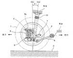
本発明によるマルチリンク式リア懸架装置は、図1ないし図5に示すようにナックル2、リアサブフレーム3、アッパアーム4、ロアアーム5、スタビライザ6、アシストアーム7、トレーリングアーム8、コイルスプリング9、ショックアブソーバ10などを備えて構成される。
ナックル2は、後輪1の内側空間に位置するように設けるが、後輪の内側空間は、後輪のタイヤの両側を平板で塞いだ時、これらの平板とホイールとの内側がなす空間にあたる。As shown in FIGS. 1 to 5, the multi-link type rear suspension device according to the present invention includes a
The
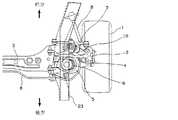
即ち、図3と図5に示すように、ナックル2は後輪1の内側に埋没して後輪1の外部に殆ど現われない状態になっている。
リアサブフレーム3は、車幅方向に配置された状態で両端がブッシュを介して車体側と結合し、または車体側と直接結合することによって車体下側の剛性を増進させる役割を有する。
アッパアーム4は、その一端が後輪1の内側空間に位置してナックル2の上端部とボールジョイントを通じて結合し、反対側の他端はリアサブフレーム3にブッシュを介して結合する。
ロアアーム5は、アッパアーム4の下側に配置されながら、その一端は後輪1の内側空間に位置してナックル2の下端部とロアアーム用マウンティングブッシュ31を介して結合し、反対側の他端はリアサブフレーム3の底面にロアアーム用マウンティングブッシュ31を介して結合する。That is, as shown in FIGS. 3 and 5, the
The
One end of the
While the
スタビライザ6は、車体の後方側にリアサブフレーム3と平行に車幅方向に配置され、その両端はナックル2側とブッシュを介して結合する。
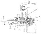
アシストアーム7は、リアサブフレーム3を基準として車体の前方側に配置され、その一端はナックル2とアシストアーム用マウンティングブッシュ15を介して結合し、反対側の他端はリアサブフレーム3の一側面とアシストアーム用マウンティングブッシュ15を介して結合する。
トレーリングアーム8は、アシストアーム7の下側で車体の前後方向に沿って配置され、その一端はナックル2とブッシュを介して結合し、反対側の他端は車体側とブッシュを介して結合する。The
The
The
コイルスプリング9は、その下端がロアアーム5上に形成された安着溝5aに挿入して固定され、反対側の上端はスプリングシート9aを通じて車体側と結合する。
ショックアブソーバ10は、路面Rと垂直方向に後輪1の中心(C)を貫通する中心線(CL1)に対して所定のオフセット角度(θ1)を有するように配置され、その下端はロアアーム5とアシストアーム7との間の空間を通過してナックル2の下端部と結合し、反対側の上端は車体側と結合する(中心線CL2は、ショックアブソーバの中心線である)。
ここで、アッパアーム4は、リアサブフレーム3と結合する先端が前方端部4aと後方端部4bとに分岐し、各端部はブッシュを介してリアサブフレーム3と結合する。The lower end of the
The
Here, the tip of the
ショックアブソーバ10は、オフセット角度(θ1)で車体前方側に傾き、ロアアーム5の両端の中心を一直線に連結した長さ(L4)は、アシストアーム7の両端の中心を一直線に連結した長さ(L5)より長く形成する。
さらに、ロアアーム5は、ナックル2と結合した一端の位置よりリアサブフレーム3の底面と結合した他端の位置が後輪1の中心を横方向に連結した中心線(CL3)に対して車体の後方側へさらに移動した状態で装着される。
この時、中心線(CL3)とロアアーム5の両端を連結する直線との間には、所定のオフセット角度θ2が形成される。The
Further, the
At this time, a predetermined offset angle θ2 is formed between the center line (CL3) and a straight line connecting both ends of the
そして、アシストアーム7は、ナックル2と結合した一端の位置よりリアサブフレーム3の一側面に結合した他端の位置が後輪1の中心を横方向に連結した中心線CL3に対して車体の前方側へさらに移動した状態で装着される。
この時、中心線(CL3)とアシストアーム7の両端を連結する直線との間には、所定のオフセット角度(θ3)が形成される。
一方、ロアアーム5の中心線(CL3)に対するオフセット角度(θ2)はアシストアーム7の中心線(CL3)に対するオフセット角度(θ3)より大きい角度を有するように設置する。The
At this time, a predetermined offset angle (θ3) is formed between the center line (CL3) and a straight line connecting both ends of the
On the other hand, the offset angle (θ2) with respect to the center line (CL3) of the
上記のような構造を有する本発明によるマルチリンクリア懸架装置は、ナックル2が後輪1の内側空間に位置するようにその大きさが大幅に縮小し、アッパアーム4は従来の一般的なダブルウィッシュボーン(double wishbone)タイプの場合より下向きに配置されてその一端がナックル2と結合し、またショックアブソーバ10はその下端がロアアーム5とアシストアーム7との間の空間を通過してナックル2と結合することにより、トランクルームの空間を形成するリアホイールハウスパネル21を図5に示すようにショックアブソーバ10が移動した距離だけ下降させて形成することができる。 The multi-link rear suspension according to the present invention having the above-described structure is greatly reduced in size so that the
これによって、本発明のマルチリンクリア懸架装置を車両に適用すれば、トランクルームの空間を従来に比べて大幅に増大させることができる。
そして、本発明は、アッパアーム4の一端が前方端部4aと後方端部4bに分岐する構造であるため、路面から伝達される振動及び衝撃等は、前方端部4aと後方端部4bを通じて分散する効果がある。
このように、アッパアーム4の所定部位に応力集中する構造を避けることにより振動及び衝撃が分散効果し、アッパアーム4の耐久性が増大する効果を得るようになる。
さらに、本発明のアッパアーム4は、従来のように直接車体側に連結するのではなくリアサブフレーム3に結合することにより、アッパアーム4に伝達した路面の振動及び衝撃などをリアサブフレーム3を通過する過程で大幅に絶縁する。As a result, if the multi-link rear suspension device of the present invention is applied to a vehicle, the space of the trunk room can be greatly increased compared to the conventional case.
In the present invention, since one end of the
Thus, by avoiding the structure in which stress concentrates on a predetermined part of the
Furthermore, the
特に、リアサブフレーム3がブッシュを通じて車体に結合している車両の場合には、室内騒音の減少と乗り心地の向上に、さらに大きく寄与できる。
そして、本発明は、ショックアブソーバ10のオフセット角度(θ1)を最小にすることで、路面から外力が伝達する時に応答性を良くすることができ、これによってダンピング性能の増大を図ることができ車両の乗り心地が大きく向上する。In particular, in the case of a vehicle in which the
In the present invention, by minimizing the offset angle (θ1) of the shock absorber 10, the responsiveness can be improved when an external force is transmitted from the road surface, thereby increasing the damping performance and the vehicle. The ride comfort is greatly improved.
さらに、本発明は、コイルスプリング9とショックアブソーバ10を分散して設けることによって、路面から伝達してくる外力もコイルスプリング9とショックアブソーバ10とを通じて分散させることができるようになり、これによって車体側への伝達が最小に止まり乗り心地を向上させることができる。
そして、本発明は、アッパアーム4を下向きに配置すると同時に、上記のようにコイルスプリング9とショックアブソーバ10とを分散して設けることにより、従来のコイルスプリングが外挿されたショックアブソーバ及びアッパアームを避けるために曲がっていたサイドメンバ23の形状は、図6に示すように直線化が可能になる。Furthermore, according to the present invention, by providing the
In the present invention, the
これによって、後方衝突事故発生時には、直線化したサイドメンバ23によって衝撃エネルギーの吸収力が増大することにより、搭乗客の安全はさらに効果的に保障される。
そして、本発明のリアサスペンションは、制動時の後輪1に若干のトーイン(toe−in)形状が発生するようにすることによって、制動安全性も確保することができる利点がある。
即ち、制動の時には図7に示すように後輪1に外力(F)が発生する。
この時、ロアアーム5は、リアサブフレーム3との結合点(A)を中心に軌跡(T1)に沿って反時計方向に転回しようとする力を有するようになり、アシストアーム7は、リアサブフレーム3との結合点(B)を中心に軌跡(T2)に沿って反時計方向に転回しようとする力を有するようになる。As a result, when the rear collision accident occurs, the absorbing ability of the impact energy is increased by the
The rear suspension of the present invention has an advantage that braking safety can be ensured by generating a slight toe-in shape on the
That is, during braking, an external force (F) is generated on the
At this time, the
これによって、ロアアーム5とナックル2との結合点(CN)は、軌跡(T1)によって後輪1の内側に入って行く移動(図面上の左側に移動)をするようになり、アシストアーム7とナックル2との結合点(D)は、軌跡(T2)によって後輪1の外側に出る移動(図面上の右側に移動)をするようになる。
従って、制動時の外力(F)を受ける後輪1では、その先方が細くなるようになるトーイン現象が発生し、このようなトーイン現象を通じて車両は安定した制動性を確保することができる。
さらに、本発明のリア懸架装置は、横力作用時のロアアーム5に結合したロアアーム用マウンティングブッシュ31の弾性係数よりアシストアーム7に結合したアシストアーム用マウンティングブッシュ15の弾性係数を弱くチューニングさせれば、旋回走行時に後方旋回外輪にトーイン現象が発生するようになる。As a result, the coupling point (CN) between the
Therefore, the
Further, in the rear suspension device of the present invention, if the elastic coefficient of the assist
即ち、後方旋回外輪に作用する横力に対して、ロアアーム側よりはアシストアーム側が車体の内側にやや収縮するようになりトーイン現象が発生する。
このようなトーイン現象は、結局車両がアンダステア(understeer)の特性を有するようにして、旋回走行中の車両はより安定した旋回性を確保することができるようになる。
ところで、アシストアーム用マウンティングブッシュ15の変形だけによって得られる後方旋回外輪のトーイン特性は、車両の高速急旋回時に作用する大変大きい横力に対しては充分でない可能性がある。
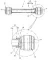
従って、図8と図9には、上記のような高速の急旋回走行時にも旋回外輪のトーイン特性を充分に確保するようにし、車両の安全性を極大化させるようにしたアシストアームの構造を開示した。That is, with respect to the lateral force acting on the rear turning outer wheel, the assist arm side slightly contracts to the inside of the vehicle body rather than the lower arm side, and a toe-in phenomenon occurs.
Such a toe-in phenomenon eventually makes the vehicle have an understeer characteristic, so that the vehicle that is turning can secure more stable turning characteristics.
By the way, the toe-in characteristic of the rear turning outer wheel obtained only by the deformation of the assist
Accordingly, FIGS. 8 and 9 show the structure of the assist arm that ensures sufficient toe-in characteristics of the turning outer wheel and maximizes the safety of the vehicle even during high-speed sudden turning as described above. Disclosed.
即ち、アシストアーム7は、アシストアーム用マウンティングブッシュ15がそれぞれ嵌められた2つのブッシュパイプ12と、2つのブッシュパイプ12を連結する連結ロッド13とから構成し;連結ロッド13は、外力によって長さ変化が可能なように互いに差込まれたインナロッド13aとアウタロッド13bとの組立体からなる。
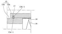
アウタロッド13bの方のブッシュパイプ12とインナロッド13aの端部との間には弾性部材16が設けられ;アウタロッド13bの内周面にはインナロッド13aの離脱を防止するスナップリング17が設けられ;アウタロッド13b内に位置するインナロッド13aの端部にはスナップリング17に係止する係止顎部13a−1が備えられた構造である。That is, the
An
アウタロッド13bの内周面には、インナロッド13aとの摩擦を最小にするための潤滑剤としてグリース(grease)18を塗布した。
弾性部材16は、圧縮コイルスプリングであることが好ましいが、板スプリングなどを使用することもでき、アシストアーム用マウンティングブッシュ15の弾性係数より大きい弾性係数を有し、旋回走行時に作用する横力に対してアシストアーム用マウンティングブッシュ15の変形が終われば、弾性部材16が変形するようにした。
アウタロッド13bの端部内周面には、断面を四角形状にしたリング設置溝13b−1を形成し、このリング設置溝13b−1にスナップリング17を装着し、インナロッドの係止顎部13a−1と係止してインナロッド13aの離脱を防止する。
The
A
上記のように構成したアシストアーム7を備えるマルチリンクリア懸架装置は、普通の旋回走行時にはアシストアーム用マウンティングブッシュ15だけを変形しながら、後方旋回外輪のトーイン特性を得るように作用する。高速の急旋回走行時に後方旋回外輪により大きい横力が作用すれば、アシストアーム用マウンティングブッシュ15の変形と共に弾性部材16が変形しながら、連結ロッド13自体の長さが短くなり、必要な後方旋回外輪のトーイン特性を充分に確保できるようにし、車両の旋回安全性が極度に向上する。 The multi-link rear suspension device including the
1 後輪
2 ナックル
3 リアサブフレーム
4 アッパアーム
5 ロアアーム
6 スタビライザ
7 アシストアーム
8 トレーリングアーム
9 コイルスプリング
10 ショックアブソーバ
13 連結ロッド
13a インナロッド
13b アウタロッド
16 弾性部材
17 スナップリング1
Claims (5)
Translated fromJapanese車幅方向に配置した状態で車体側に結合して車体下側の剛性を増進させるリアサブフレームと、
一端は前記後輪の内側空間に位置して前記ナックルの上端部と結合し、他端は前記リアサブフレームに結合するアッパアームと、
前記アッパアームの下側に配置され、一端は前記後輪の内側空間に位置して前記ナックルの下端部と結合し、他端は前記リアサブフレームに結合するロアアームと、
前記ロアアームの両端にそれぞれ備えられ、前記ナックルと前記リアサブフレームにそれぞれ結合するロアアーム用マウンティングブッシュと、
前記リアサブフレームを基準として車体の前方側に配置され、一端は前記ナックルに結合し、他端は前記リアサブフレームに結合し、2つのブッシュパイプと、インナロッドとアウタロッドとの組立体からなる連結ロッドとからなるアシストアームと、
前記アウタロッド側のブッシュパイプと前記インナロッドの端部との間に設けられた弾性部材と、
前記アシストアームの両端にそれぞれ備えられ、前記ナックルと前記リアサブフレームにそれぞれ結合するアシストアーム用マウンティングブッシュと、
前記アシストアームの下側で車体の前後方向に沿って配置されながら、一端は前記ナックルに結合し、他端は車体側に結合するトレーリングアームと、
前記ロアアーム上に形成された安着溝に下端が挿入されて固定され、上端は車体側に結合するコイルスプリングと、
路面に対して垂直な方向に前記後輪の中心を貫通する中心線に対して所定のオフセット角度(θ1)を有するように配置された状態であり、下端は前記ロアアームと前記アシストアームとの間の空間を通じてナックルと結合し、上端は車体側に結合するショックアブソーバと、
を含んで構成されるマルチリンクリア懸架装置であって、
前記弾性部材は、前記アシストアーム用マウンティングブッシュより弾性係数が大きく、
前記アシストアーム用マウンティングブッシュは、前記ロアアーム用マウンティングブッシュより弾性係数が小さいことを特徴とするマルチリンクリア懸架装置。A knuckle thatis provided so as to be located inside the space of the rear wheel,
A rear sub-frame that is connected to the vehicle body side in a state of being arranged in the vehicle width direction and increases rigidity on the vehicle body lower side;
One end is located in the inner space of the rear wheel and is coupled to the upper end of the knuckle, and the other end is coupled to the rear subframe,
A lower arm that is disposed on the lower side of the upper arm, has one end located in the inner space of the rear wheel and coupled to the lower end of the knuckle, and the other end coupled to the rear subframe;
Lower arm mounting bushes respectively provided at both ends of the lower arm and coupled to the knuckle and the rear subframe,
Arranged on the front side of the vehicle body with respect to the rearsubframe , one end is coupled to the knuckle and the other end is coupled to the rear subframe, and comprises an assembly of two bush pipes, an inner rod and an outer rod. An assist armcomprising a connecting rod ;
An elastic member provided between a bush pipe on the outer rod side and an end of the inner rod;
Assist arm mounting bushes respectively provided at both ends of the assist arm and coupled to the knuckle and the rear subframe,
A trailing arm that is disposed along the longitudinal direction of the vehicle body on the lower side of the assist arm, and has one end coupled to the knuckle and the other end coupled to the vehicle body side;
A lower end is inserted into the seating groove formed on the lower arm and fixed, and the upper end is a coil spring coupled to the vehicle body side;
It is arranged so as to have a predetermined offset angle (θ1) with respect to a center line passing through the center of the rear wheel in a direction perpendicular to the road surface, and the lower end is between the lower arm and the assist arm. A shock absorber that is coupled to the knuckle through the space and the upper end is coupled to the vehicle body side,
A multi-link rear suspension system comprising:
The elastic member has a larger elastic coefficient than the assist arm mounting bush,
The multi-link rear suspension apparatus,wherein the assist arm mounting bush has a smaller elastic coefficient than the lower arm mounting bush .
前記アウタロッド内に位置するインナロッドの端部には、前記スナップリングに係止する係止顎部が備えられたことを特徴とする請求項1に記載のマルチリンクリア懸架装置。
A snap ring for preventing the inner rod from being detached is provided on the inner peripheral surface of the outer rod,
2. The multi-link rear suspension apparatus according to claim 1, wherein an end portion of an inner rod positioned in the outer rod is provided with a locking jaw portion that is locked to the snap ring.
Applications Claiming Priority (5)
| Application Number | Priority Date | Filing Date | Title |
|---|---|---|---|
| KR2003-088383 | 2003-12-06 | ||
| KR20030088383 | 2003-12-06 | ||
| KR1020040048127AKR100599290B1 (en) | 2003-12-06 | 2004-06-25 | multi link rear suspension |
| KR2004-048127 | 2004-06-25 | ||
| FR0412964AFR2863206B1 (en) | 2003-12-06 | 2004-12-06 | MULTI LINK REAR SUSPENSION SYSTEM |
Publications (2)
| Publication Number | Publication Date |
|---|---|
| JP2005170377A JP2005170377A (en) | 2005-06-30 |
| JP4748765B2true JP4748765B2 (en) | 2011-08-17 |
Family
ID=34753395
Family Applications (1)
| Application Number | Title | Priority Date | Filing Date |
|---|---|---|---|
| JP2004352892AExpired - Fee RelatedJP4748765B2 (en) | 2003-12-06 | 2004-12-06 | Multilink rear suspension system |
Country Status (4)
| Country | Link |
|---|---|
| US (1) | US7243934B2 (en) |
| JP (1) | JP4748765B2 (en) |
| AU (1) | AU2004236571B2 (en) |
| FR (1) | FR2863206B1 (en) |
Families Citing this family (37)
| Publication number | Priority date | Publication date | Assignee | Title |
|---|---|---|---|---|
| EP1462343B1 (en)* | 2003-03-28 | 2007-07-11 | Ford Global Technologies, LLC, A subsidary of Ford Motor Company | Wheel suspension for a motor vehicle |
| JP2005225382A (en)* | 2004-02-13 | 2005-08-25 | Honda Motor Co Ltd | Vehicle rear suspension device |
| DE102005030810A1 (en)* | 2005-07-01 | 2007-01-18 | Audi Ag | Independent suspension for the rear wheels of motor vehicles |
| JP4305429B2 (en)* | 2005-08-18 | 2009-07-29 | トヨタ自動車株式会社 | In-wheel suspension |
| JP4491790B2 (en)* | 2005-08-26 | 2010-06-30 | 東海ゴム工業株式会社 | Anti-vibration connecting rod |
| JP4779582B2 (en)* | 2005-11-10 | 2011-09-28 | 日産自動車株式会社 | In-wheel drive unit suspension system |
| SE532107C2 (en)* | 2006-11-03 | 2009-10-27 | Swedish Advanced Automotive Bu | Wheel suspension arrangement and motor vehicles |
| JP2008195296A (en)* | 2007-02-14 | 2008-08-28 | Honda Motor Co Ltd | Suspension device |
| WO2008120069A1 (en)* | 2007-03-29 | 2008-10-09 | Nissan Motor Co., Ltd. | Vehicle suspension device |
| CN101622141B (en)* | 2007-04-04 | 2011-07-13 | 日产自动车株式会社 | Suspension device for wheels |
| DE102007063545A1 (en)* | 2007-12-21 | 2009-06-25 | Dr. Ing. H.C. F. Porsche Aktiengesellschaft | Wheel suspension for the rear wheels of a motor vehicle |
| JP5141961B2 (en)* | 2008-03-26 | 2013-02-13 | マツダ株式会社 | Vehicle suspension subframe structure |
| JP5514808B2 (en)* | 2009-04-21 | 2014-06-04 | 本田技研工業株式会社 | Suspension device |
| US8746719B2 (en) | 2010-08-03 | 2014-06-10 | Polaris Industries Inc. | Side-by-side vehicle |
| JP5625644B2 (en)* | 2010-09-07 | 2014-11-19 | 日産自動車株式会社 | Car suspension equipment |
| DE102010048846A1 (en)* | 2010-10-19 | 2012-04-19 | Gm Global Technology Operations Llc (N.D.Ges.D. Staates Delaware) | motor vehicle |
| JP5293770B2 (en) | 2011-05-16 | 2013-09-18 | 日産自動車株式会社 | Suspension structure, suspension link arrangement method |
| EP2540534B1 (en)* | 2011-05-16 | 2014-10-29 | Nissan Motor Co., Ltd | Suspension structure, bush structure and suspension characteristic adjusting method |
| CN104136244B (en)* | 2012-02-23 | 2016-08-24 | 丰田自动车株式会社 | Suspension device for vehicle |
| DE102013205335A1 (en)* | 2013-03-26 | 2014-10-02 | Ford Global Technologies, Llc | Independent suspension for the non-driven wheels of a vehicle |
| ITTO20130354A1 (en) | 2013-05-02 | 2014-11-03 | Fiat Group Automobiles Spa | MOTOR VEHICLE SUSPENSION SYSTEM OF THE MULTI-LINK TYPE, WITH TRANSVERSAL LAMINA SPRING |
| US9579942B2 (en) | 2014-02-27 | 2017-02-28 | Ford Global Technologies, Llc | Integral 5-link independent suspension systems |
| JP6482110B2 (en)* | 2014-09-22 | 2019-03-13 | 株式会社Subaru | Suspension device |
| US9981519B2 (en) | 2015-01-29 | 2018-05-29 | Bombardier Recreational Products Inc. | Rear suspension assembly for an off-road vehicle |
| CN106515332A (en)* | 2015-09-11 | 2017-03-22 | 广州汽车集团股份有限公司 | Rear suspension system of vehicle and vehicle having same |
| ITUB20153561A1 (en)* | 2015-09-11 | 2017-03-11 | Fca Italy Spa | "Suspension of rear wheel of motor vehicle, with independent wheels" |
| CN106671721B (en)* | 2015-11-06 | 2019-11-22 | 广州汽车集团股份有限公司 | Vehicle rear suspension system and vehicle having same |
| US10967694B2 (en) | 2017-12-21 | 2021-04-06 | Polaris Industries Inc. | Rear suspension assembly for a vehicle |
| US11260773B2 (en) | 2018-01-09 | 2022-03-01 | Polaris Industries Inc. | Vehicle seating arrangements |
| DE102018101280A1 (en) | 2018-01-22 | 2019-07-25 | Dr. Ing. H.C. F. Porsche Aktiengesellschaft | Axle device for the connection of a wheel to the body of a vehicle |
| CN108528202A (en)* | 2018-05-29 | 2018-09-14 | 吉林大学 | New-energy automobile wheel hub motor gate-type rear axle assy |
| US10974560B2 (en)* | 2018-11-14 | 2021-04-13 | Rivian Ip Holdings, Llc | Suspension with jounce bumper balanced for caster control |
| GB2582642B (en)* | 2019-03-29 | 2021-06-16 | Protean Electric Ltd | A double wishbone suspension system for an in-wheel electric motor |
| US11370258B2 (en)* | 2020-09-28 | 2022-06-28 | Ford Global Technologies, Llc | Trailing blade suspension system with angled blade |
| DE102021122012A1 (en)* | 2021-08-25 | 2023-03-02 | Bayerische Motoren Werke Aktiengesellschaft | wheel suspension of a vehicle |
| CN114013233B (en)* | 2021-11-03 | 2024-07-09 | 奇瑞汽车股份有限公司 | Vehicle rear suspension upper control arm and vehicle |
| KR102755945B1 (en)* | 2022-09-29 | 2025-01-21 | (주)화신 | Suspension for vehicle with leaf spring |
Family Cites Families (36)
| Publication number | Priority date | Publication date | Assignee | Title |
|---|---|---|---|---|
| ES328436A1 (en)* | 1965-07-13 | 1967-04-01 | Pirelli | A perfection in the suspensions of the autovehiculos. (Machine-translation by Google Translate, not legally binding) |
| DE3048794C1 (en)* | 1980-12-23 | 1982-08-12 | Daimler-Benz Ag, 7000 Stuttgart | Independent wheel suspension for motor vehicles |
| JPH0694244B2 (en)* | 1986-04-25 | 1994-11-24 | マツダ株式会社 | Car suspension |
| JPH0694243B2 (en)* | 1986-04-25 | 1994-11-24 | マツダ株式会社 | Car suspension |
| EP0242883B1 (en)* | 1986-04-25 | 1992-02-26 | Mazda Motor Corporation | Vehicle suspension system having toe direction control means |
| JPS63154412A (en)* | 1986-12-19 | 1988-06-27 | Mazda Motor Corp | Suspension link device for automobile |
| DE3716706A1 (en)* | 1987-05-19 | 1988-12-08 | Daimler Benz Ag | INDEPENDENT WHEEL SUSPENSION FOR STEERING WHEELS OF MOTOR VEHICLES |
| JPH023503A (en)* | 1988-06-22 | 1990-01-09 | Mitsubishi Motors Corp | Independent suspension for steering wheel |
| JPH02249712A (en)* | 1989-03-23 | 1990-10-05 | Toyota Motor Corp | Suspension device for vehicle |
| US4989894A (en)* | 1989-10-30 | 1991-02-05 | Chrysler Corporation | Independent rear suspension |
| JPH03217305A (en)* | 1990-01-24 | 1991-09-25 | Mitsubishi Motors Corp | Vibration proof structure of lateral rod |
| JP3132511B2 (en)* | 1991-01-10 | 2001-02-05 | マツダ株式会社 | Car suspension support structure |
| FR2674187A1 (en)* | 1991-03-20 | 1992-09-25 | Peugeot | Device forming a suspension, particularly for the rear wheel of a motor vehicle |
| JP2914028B2 (en)* | 1992-08-17 | 1999-06-28 | 日産自動車株式会社 | Vehicle suspension device |
| JPH08108720A (en)* | 1994-10-07 | 1996-04-30 | Nissan Motor Co Ltd | Vehicle rear suspension |
| JP3085117B2 (en)* | 1995-01-11 | 2000-09-04 | トヨタ自動車株式会社 | Suspension device |
| JP3669642B2 (en)* | 1995-01-17 | 2005-07-13 | 本田技研工業株式会社 | Vehicle suspension system |
| JP3381475B2 (en)* | 1995-09-13 | 2003-02-24 | 日産自動車株式会社 | Rear suspension for vehicles |
| JPH0976714A (en)* | 1995-09-13 | 1997-03-25 | Nissan Motor Co Ltd | Rear suspension for vehicles |
| JP3724063B2 (en)* | 1996-06-20 | 2005-12-07 | 日産自動車株式会社 | Suspension device |
| IT1289745B1 (en) | 1996-12-13 | 1998-10-16 | Fiat Ricerche | REAR SUSPENSION OF VEHICLE |
| JP3769854B2 (en)* | 1997-01-20 | 2006-04-26 | 日産自動車株式会社 | Suspension spring upper mount structure |
| DE59809491D1 (en)* | 1997-03-01 | 2003-10-09 | Opel Adam Ag | REAR SUSPENSION OF A MOTOR VEHICLE |
| DE20023581U1 (en)* | 1999-03-06 | 2004-12-02 | Dr.Ing.H.C. F. Porsche Ag | Wheel suspension for driven rear wheels of a motor vehicle |
| DE20023579U1 (en)* | 1999-05-03 | 2004-12-16 | Dr.Ing.H.C. F. Porsche Ag | Wheel suspension for a front axle of a motor vehicle |
| US6240806B1 (en)* | 1999-09-08 | 2001-06-05 | The Boler Company | Cam shaft support and enclosure assembly |
| JP2001130232A (en)* | 1999-11-08 | 2001-05-15 | Nissan Motor Co Ltd | Steering wheel suspension device |
| US6241267B1 (en)* | 1999-12-07 | 2001-06-05 | R. J. Tower Corporation | Control arm for use in vehicle suspension system |
| DE10014878A1 (en)* | 2000-03-24 | 2001-09-27 | Volkswagen Ag | Multi-link wheel suspension for motor vehicles has wheel carrier with integrated fastening legs for connection joints for longitudinal links to permits compensation movement of wheel carrier about shaft |
| JP3904825B2 (en)* | 2000-11-01 | 2007-04-11 | 本田技研工業株式会社 | Suspension structure attached to the die-cast subframe |
| KR100448791B1 (en)* | 2002-02-22 | 2004-09-16 | 현대자동차주식회사 | a mounting part structure of floor and rear suspension in vehicles |
| ITTO20020903A1 (en)* | 2002-10-17 | 2004-04-18 | Fiat Ricerche | DEVICE FOR THE STEERING OF A HUB HOLDER FOR THE |
| US6755429B1 (en)* | 2003-05-06 | 2004-06-29 | Ford Global Technologies, Llc | Independent suspension for rear wheels of automotive vehicle |
| JP2005225382A (en)* | 2004-02-13 | 2005-08-25 | Honda Motor Co Ltd | Vehicle rear suspension device |
| JP4360227B2 (en)* | 2004-02-19 | 2009-11-11 | マツダ株式会社 | Suspension device |
| US20060071441A1 (en)* | 2004-10-06 | 2006-04-06 | William Mathis | Lower control arm kit for vehicle with four link rear suspension |
- 2004
- 2004-12-06USUS11/005,405patent/US7243934B2/enactiveActive
- 2004-12-06JPJP2004352892Apatent/JP4748765B2/ennot_activeExpired - Fee Related
- 2004-12-06AUAU2004236571Apatent/AU2004236571B2/ennot_activeCeased
- 2004-12-06FRFR0412964Apatent/FR2863206B1/ennot_activeExpired - Fee Related
Also Published As
| Publication number | Publication date |
|---|---|
| AU2004236571B2 (en) | 2011-06-16 |
| AU2004236571A1 (en) | 2005-06-23 |
| FR2863206B1 (en) | 2010-08-13 |
| FR2863206A1 (en) | 2005-06-10 |
| JP2005170377A (en) | 2005-06-30 |
| US7243934B2 (en) | 2007-07-17 |
| US20050140110A1 (en) | 2005-06-30 |
Similar Documents
| Publication | Publication Date | Title |
|---|---|---|
| JP4748765B2 (en) | Multilink rear suspension system | |
| US10556474B2 (en) | Front suspension structure of automotive vehicle | |
| US7427113B2 (en) | Ball and socket mount for shock absorber of torsion beam axle suspension | |
| KR101461902B1 (en) | Coupled torsion beam axle type suspension system | |
| KR101461916B1 (en) | Coupled torsion beam axle type suspension system | |
| KR100461602B1 (en) | Bush for suspension of vehicle | |
| CN100457481C (en) | Multi-link rear-suspension system | |
| KR100599290B1 (en) | multi link rear suspension | |
| KR100911406B1 (en) | Subframe for the front suspension of the vehicle | |
| US20060091721A1 (en) | Torsion beam suspension system for automobiles and method of manufacturing the same | |
| KR101491180B1 (en) | Torsion beam axle type rear suspension system and manufacture method for vehicle | |
| KR20110075830A (en) | Rear suspension | |
| KR101338429B1 (en) | Sub-frame for front suspension of automobile device for vehicle | |
| KR100369145B1 (en) | Automotive driven-wheel suspension system | |
| KR100527720B1 (en) | Rear suspension in bus | |
| KR100559876B1 (en) | Body side mounting structure of trailing arm | |
| KR20070094086A (en) | Reinforcement Structure of Coupled Torsion Beam Type Suspension for Vehicle | |
| KR100793902B1 (en) | Vehicle Rear Suspension | |
| JP4654859B2 (en) | Suspension device | |
| KR20020051760A (en) | The compound torsion beam axle typed suspension having double cushioned action | |
| KR20110139605A (en) | Stabilizer Bar Mounting Units for Vehicle Suspension | |
| KR20040001664A (en) | Variable type torsion bar of rear suspension | |
| KR100699483B1 (en) | Car suspension | |
| KR100457196B1 (en) | Upper Arm Reinforcement | |
| KR20140077040A (en) | Spring mounting unit for multi-link type suspension system |
Legal Events
| Date | Code | Title | Description |
|---|---|---|---|
| A621 | Written request for application examination | Free format text:JAPANESE INTERMEDIATE CODE: A621 Effective date:20071203 | |
| A131 | Notification of reasons for refusal | Free format text:JAPANESE INTERMEDIATE CODE: A131 Effective date:20100518 | |
| A521 | Request for written amendment filed | Free format text:JAPANESE INTERMEDIATE CODE: A523 Effective date:20100818 | |
| A131 | Notification of reasons for refusal | Free format text:JAPANESE INTERMEDIATE CODE: A131 Effective date:20101026 | |
| A521 | Request for written amendment filed | Free format text:JAPANESE INTERMEDIATE CODE: A523 Effective date:20110124 | |
| TRDD | Decision of grant or rejection written | ||
| A01 | Written decision to grant a patent or to grant a registration (utility model) | Free format text:JAPANESE INTERMEDIATE CODE: A01 Effective date:20110510 | |
| A01 | Written decision to grant a patent or to grant a registration (utility model) | Free format text:JAPANESE INTERMEDIATE CODE: A01 | |
| A61 | First payment of annual fees (during grant procedure) | Free format text:JAPANESE INTERMEDIATE CODE: A61 Effective date:20110516 | |
| R150 | Certificate of patent or registration of utility model | Ref document number:4748765 Country of ref document:JP Free format text:JAPANESE INTERMEDIATE CODE: R150 Free format text:JAPANESE INTERMEDIATE CODE: R150 | |
| FPAY | Renewal fee payment (event date is renewal date of database) | Free format text:PAYMENT UNTIL: 20140527 Year of fee payment:3 | |
| R250 | Receipt of annual fees | Free format text:JAPANESE INTERMEDIATE CODE: R250 | |
| R250 | Receipt of annual fees | Free format text:JAPANESE INTERMEDIATE CODE: R250 | |
| R250 | Receipt of annual fees | Free format text:JAPANESE INTERMEDIATE CODE: R250 | |
| R250 | Receipt of annual fees | Free format text:JAPANESE INTERMEDIATE CODE: R250 | |
| R250 | Receipt of annual fees | Free format text:JAPANESE INTERMEDIATE CODE: R250 | |
| LAPS | Cancellation because of no payment of annual fees |