JP4747676B2 - Electronic equipment and electronic equipment system - Google Patents
Electronic equipment and electronic equipment systemDownload PDFInfo
- Publication number
- JP4747676B2 JP4747676B2JP2005155313AJP2005155313AJP4747676B2JP 4747676 B2JP4747676 B2JP 4747676B2JP 2005155313 AJP2005155313 AJP 2005155313AJP 2005155313 AJP2005155313 AJP 2005155313AJP 4747676 B2JP4747676 B2JP 4747676B2
- Authority
- JP
- Japan
- Prior art keywords
- external device
- key
- electronic device
- backlight
- information
- Prior art date
- Legal status (The legal status is an assumption and is not a legal conclusion. Google has not performed a legal analysis and makes no representation as to the accuracy of the status listed.)
- Expired - Lifetime
Links
Images

Landscapes
- Controls And Circuits For Display Device (AREA)
- Liquid Crystal (AREA)
- Liquid Crystal Display Device Control (AREA)
- Control Of Indicators Other Than Cathode Ray Tubes (AREA)
Description
Translated fromJapaneseこの発明は、電子機器及び電子機器システムに関する。 The present invention relates to an electronic device and an electronic device system.
ポータブルHDDプレーヤは、楽曲等の音響情報を蓄積して利用者に提供することが可能であると共に、その音響情報を蓄積する容量も大きいので、広く利用されつつある。 Portable HDD players are being widely used because they can store acoustic information such as music and provide it to users and have a large capacity for storing the acoustic information.
従来のポータブルHDDプレーヤには、例えば特許文献1に記載されたものがある。
特許文献1のポータブルHDDプレーヤのケースには、利用者が操作や設定を行うための各種キーが配置されるとともに、設定内容等を表示する液晶表示装置が配置されている。このポータブルHDDプレーヤは、電池を内蔵し、この電池を駆動電源としている。さらに、このポータブルHDDプレーヤには、外部機器を接続するための端子が設けられている。 In the case of the portable HDD player of Patent Document 1, various keys for a user to perform operations and settings are arranged, and a liquid crystal display device that displays setting contents and the like is arranged. This portable HDD player incorporates a battery and uses this battery as a driving power source. Further, this portable HDD player is provided with a terminal for connecting an external device.
外部機器を接続する端子に外部機器を接続し、外部機器に設けられたキーを操作することにより、利用者の所望する楽曲等の再生が可能になる。しかしながら、ポータブルHDDプレーヤの液晶表示装置や、そのバックライトや、ポータブルHDDプレーヤの各種キーの周辺を明るくするLED等は、低消費電力のために、特定のキーが押下されないと点灯しない構成になっている。 By connecting an external device to a terminal to which the external device is connected and operating a key provided on the external device, it is possible to reproduce music or the like desired by the user. However, the liquid crystal display device of the portable HDD player, its backlight, and the LEDs that brighten the periphery of various keys of the portable HDD player are configured so that they do not light up unless a specific key is pressed because of low power consumption. ing.
したがって、外部機器のキーを操作しても、ポータブルHDDプレーヤの液晶表示装置や、そのバックライトや、ポータブルHDDプレーヤの各種キーの周辺を明るくするLED等が点灯しない。これらを点灯させるためには、利用者がポータブルHDDプレーヤの特定のキーを操作する必要があり、不便であった。 Therefore, even when the keys of the external device are operated, the liquid crystal display device of the portable HDD player, the backlight thereof, and the LEDs that brighten the periphery of the various keys of the portable HDD player are not lit. In order to light these, it is necessary for the user to operate a specific key of the portable HDD player, which is inconvenient.
本発明は、このような現状に鑑みてなされた発明であり、ポータブルHDDプレーヤ等の音響機器のように、蓄積した情報を提供する電子機器の利便性を向上させることを目的とする。 The present invention has been made in view of such a situation, and an object thereof is to improve the convenience of an electronic device that provides stored information, such as an audio device such as a portable HDD player.
上記目的を達成するために、本発明の第1の観点に係る電子機器は、
情報を蓄積する蓄積手段とこれを内蔵する筐体とを備え、
前記筐体にはキーと液晶表示パネルと前記液晶表示パネルのバックライトと外部機器接続用の入力端子とが配置され、
前記キー或いは前記入力端子に接続された外部機器を操作することにより、前記情報を出力する電子機器であって、
前記外部機器が操作されたことを検出する検出手段と、
前記検出手段が前記外部機器が操作されたことを検出した場合に、前記バックライトを点灯させる点灯手段と、
を備えることを特徴とする。In order to achieve the above object, an electronic apparatus according to the first aspect of the present invention provides:
A storage means for storing information and a housing containing the storage means;
The housing keys and the input terminals of the liquid crystal display panel andthe liquid crystal display panel back light and the external device connection is arranged to,
An electronic device that outputs the information by operating an external device connected to the key or the input terminal,
Detecting means for detecting that the external device is operated;
Lighting means for turning on the backlight when the detecting means detects that the external device has been operated;
It is characterized by providing.
なお、前記点灯手段は、前記バックライトを点灯させてから所定時間が経過したとき前記バックライトを消灯させてもよい。
また、前記外部機器には、前記筐体のキーに割り当てられたキーが配置され、
前記検出手段は、前記筐体のキーに割り当てられた外部機器のキーのいずれかが操作されたときに前記外部機器が操作されたことを検出してもよい。Incidentally, the lighting unit may turn offthe backlight when the predetermined time by turning on the backlight has elapsed.
Theexternal device is provided with a key assigned to the key of the housing,
The detecting means may detect that the external device has been operated when any one of the keys of the external device assigned to the key of the casing is operated.
前述の本発明の第1の観点に係る電子機器において、前記蓄積手段に蓄積された情報を前記外部機器を介して出力してもよい。In the electronic apparatus according to thefirst aspect of the present invention described above, the information stored in the storage means may be output via the external apparatus.
また、前記外部機器は、前記電子機器のリモートコントローラであってもよい。Further, the external device may be a remote controller ofthe electronic device.
また、前記外部機器は、前記入力端子に対して無線で接続されてもよい。 The external device may be connected to the input terminal wirelessly.
また、前記情報は音響を表し、前記情報を再生して出力してもよい。 The information may represent sound and the information may be reproduced and output.
上記目的を達成するために、本発明の第2の観点に係る電子機器システムは、
情報を蓄積する蓄積手段、前記蓄積手段を内蔵する筐体、前記筐体に配置されたキー、前記筐体に配置された液晶表示パネル、前記液晶表示パネルのバックライト、外部機器接続用の入力端子、前記外部機器が操作されたことを検出する検出手段、及び前記検出手段が前記外部機器が操作されたことを検出した場合に前記バックライトを点灯させる点灯手段を備え、前記情報を出力する電子機器と、
前記入力端子に接続され、キーを持つ外部機器とを備え、
前記電子機器のキー或いは前記外部機器のキーの操作に基づいて前記情報を出力することを特徴とする。In order to achieve the above object, an electronic device system according to asecond aspect of the present invention includes:
Storage means for storing information, a housing which incorporatesthe storage means, the enclosure disposed key, liquid crystal display panel disposed on the housing, the backlight of the liquid crystal display panel, input for external device connection A terminal, a detection unit that detects that the external device has been operated, and a lighting unit that turns on the backlight when the detection unit detects that the external device has been operated, and outputs the information Electronic equipment,
An external device connected to the input terminal and having a key;
The information is output based on an operation of a key of the electronic device or a key of the external device.
なお、前記点灯手段は、前記バックライトを点灯させてから所定時間が経過したとき前記バックライトを消灯させてもよい。
また、前記検出手段は、前記外部機器の前記電子機器のキーに割り当てられたキーのいずれかが操作された場合に、前記外部機器が操作されたことを検出してもよい。Incidentally, the lighting unit may turn offthe backlight when the predetermined time by turning on the backlight has elapsed.
The detection unit may detect that the external device has been operated when any of keys assigned to keys of the electronic device of the external device is operated.
前述の本発明の第2の観点に係る電子機器システムにおいて、前記蓄積手段に蓄積された情報を前記外部機器を介して出力してもよい。In the electronic device system according to thesecond aspect of the present invention described above, the information stored in the storage means may be output via the external device.
また、前記外部機器は、前記電子機器のリモートコントローラであってもよい。 The external device may be a remote controller of the electronic device.
また、前記外部機器は、前記入力端子に対して無線で接続されてもよい。 The external device may be connected to the input terminal wirelessly.
また、前記蓄積手段に蓄積された情報は音響を表し、前記情報を再生して出力してもよい。 The information stored in the storage means may represent sound, and the information may be reproduced and output.
本発明によれば、外部機器の操作時に、自動的に液晶表示パネルのバックライト或いは本体キーの周辺を明るくするためのライトが点灯し、利便性が向上する。 According to the present invention, when the external device is operated, the backlight of the liquid crystal display panel or the light for brightening the periphery of the main body key is automatically turned on, which improves convenience.
以下、図面に基づき、本発明の実施の形態について詳細に説明する。
[第1の実施形態]
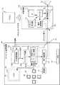
図1は、本発明の第1の観点に係る実施形態のポータブル音響機器10と外部機器30を示す構成図である。Hereinafter, embodiments of the present invention will be described in detail with reference to the drawings.
[First Embodiment]
FIG. 1 is a configuration diagram showing a
このポータブル音響機器10は、音響情報を蓄積する蓄積部11と、機器全体の駆動源となる電池12と、マイクロコンピュータ(マイコン)13と信号増幅部14とを備え、これらが筐体に内蔵されている。 The
ポータブル音響機器10の筐体には、液晶表示パネル(LCD)15と複数のキー16が配置されている。液晶表示パネル15の背面には、バックライト17が組み込まれている。また、ポータブル音響機器10の筐体には、キー16の周辺を明るくするためのLEDライト18と、外部機器30が接続される入出力ポートとしてのヘッドフォン端子19とが、組み込まれている。ポータブル音響機器10の所定のキー16を押下すると、液晶表示パネル15のバックライト17及びLEDライト18を点灯させることができる。 A liquid crystal display panel (LCD) 15 and a plurality of keys 16 are arranged in the casing of the
マイクロコンピュータ13は、ポータブル音響機器10の制御を行う手段であり、その機能には、外部機器30から与えられたアナログ信号をデジタル信号に変換するA/D変換機能13aと、そのデジタル信号で特定されたキー16が押下された場合と同様の制御信号を生成するキードライブ機能13bと、キー16が実際に押下されたことにより発生する制御信号或いはキードライブ機能13bで生成した制御信号により、信号増幅部14の増幅率等を制御するキー処理アプリーション機能13cとが、含まれる。さらに、マイクロコンピュータ13の機能には、従来にはない、点灯機能13dが追加されている。この点灯機能13dは、A/D変換機能13aによってアナログ信号から変換されたデジタル信号が、当該装置のキー16のいずれかを示す場合に、液晶表示パネル15のバックライト17及びLEDライト18を点灯させる機能である。 The
信号増幅部14は、蓄積部11から読み出した情報を、マイクロコンピュータ13のキー処理アプリケーション機能13cから与えられた制御信号で制御された増幅率で増幅する機能を持つ。 The
外部機器30は、再生音をユーザの所望する音量に調整する機器であり、マイクロコンピュータ(マイコン)31と、信号増幅部32と、電圧変換部33とを備え、これらが筐体に内蔵されている。 The
外部機器30の筐体には、ポータブル音響機器10のヘッドフォン端子19に接続されるライン入力端子34と、リモートコントローラ(リモコン)35の発生する赤外線を受光するリモコン受光部36と、複数のキー37とが配置されている。 A housing of the
信号増幅部32の入力側は、ライン入力端子34に接続され、信号増幅部32の出力側に、スピーカ38が接続されている。 The input side of the
複数のキー37には、信号増幅部32の増幅率を設定するものや、ポータブル音響機器10のキー16に割り当てられたものもある。各キー37は、マイクロコンピュータ31に接続され、どのキー37が押下されたかが、マイクロコンピュータ31によってスキャンされる。リモコン受光部36もマイクロコンピュータ31に接続され、リモートコントローラ35の操作内容がマイクロコンピュータ31に認識される構成である。マイクロコンピュータ31の発生する制御信号が電圧変換部33に入力される。電圧変換部33は電圧を発生する回路であり、入力された制御信号に応じて発生する電圧を変化させてアナログ信号を発生する。電圧変換部33の出力側が、ライン入力端子34に接続されている。この電圧変換部33の発生するアナログ信号が、マイクロコンピュータ13に入力される。 Some of the
次に、ポータブル音響機器10と外部機器30の動作を説明する。
利用者は、ポータブル音響機器10のキー16、外部機器30のキー37或いはリモートコントローラ35を操作し、蓄積部11に蓄積されている音響情報を選択すると共に、選択した音響情報の再生音の音量を設定する。Next, operations of the
The user operates the key 16 of the
ポータブル音響機器10のキー16を操作する場合には、最初に所定のキー16を選択して押下することにより、液晶表示パネル15のバックライト17とLEDライト18とが点灯し、液晶表示パネル15の表示が可視となるとともに、キー16の周辺が明るくなり、利用者の後続する操作が容易になる。 When operating the key 16 of the
リモートコントローラ35を操作してバックライト17とLEDライト18とを点灯させる場合には、リモートコントローラ35により、ポータブル音響機器10のキー16を指定する。この指定したキー16の情報は、リモコン受光部36を介してマイクロコンピュータ31に入力される。外部機器30のキー37を使用する場合には、ポータブル音響機器10のキー16に割り当てられたキー37を押下すると、押下したキー37の情報がマイクロコンピュータ31に入力される。マイクロコンピュータ31は、電圧変換部33に制御信号を与え、電圧変換部33から、入力された情報に対応するキー16を示す電圧のアナログ信号を発生させる。 When operating the
アナログ信号は、ライン入力端子34及びヘッドフォン端子19を介してマイクロコンピュータ13に入力される。A/D変換機能13aは、アナログ信号に対応するデジタル信号を発生する。キードライブ機能13bは、そのデジタル信号で特定されたキー16が押下された場合と同様の制御信号を生成する。点灯機能13dは、キードライブ機能13bで生成した制御信号に基づき、利用者がリモートコントローラ35或いは外部機器30を用いて複数のキー16のうちのいずれかを選択したことを検出し、バックライト17及びLEDライト18を点灯させる。 The analog signal is input to the
ポータブル音響機器10を操作して蓄積部11に蓄積されている音響情報を選択し、選択した音響情報の再生音の音量を設定する場合、利用者は、所定のキー16を選択して押下する。マイクロコンピュータ13のキードライブ機能13bは、押下されたキー16を特定し、そのキー16に対応する制御信号を発生し、キー処理アプリケーション機能13cがポータブル音響機器10内を制御する。 When operating the portable
例えば、押下されたキー16によって、蓄積部11に蓄積された音響情報が選択された場合には蓄積部11が制御され、その音響情報が信号増幅部14に与えられ、信号増幅部14が音響情報を再生信号に変換して出力する。押下されたキー16によって、信号増幅部14での増幅率が指定される場合には、その情報が信号増幅部14を制御するキー処理アプリーション機能13cを経由して信号増幅部14に与えられ、信号増幅部14が音響情報を再生信号として出力する際の増幅率が設定される。 For example, when the acoustic information stored in the storage unit 11 is selected by the pressed key 16, the storage unit 11 is controlled, the acoustic information is given to the
外部機器30を操作して蓄積部11に蓄積されている音響情報を選択する場合、これを設定するキー16に割当てられたキー37を選択して押下する。リモートコントローラ35を利用する場合も、音響情報を選択するキー16を指定する。これらの情報は、マイクロコンピュータ31に入力される。マイクロコンピュータ31は、電圧変換部33に制御信号を与え、入力された情報に対応するキー16を示す電圧のアナログ信号を電圧変換部33から、発生させる。 When operating the
アナログ信号は、ライン入力端子34及びヘッドフォン端子19を介してマイクロコンピュータ13に入力される。A/D変換機能13aは、アナログ信号に対応するデジタル信号を発生する。キードライブ機能13bは、そのデジタル信号で特定されたキー16が押下された場合と同様の制御信号を生成する。その制御信号に基づき、キー処理アプリケーション機能13cは蓄積部11を制御し、蓄積部11に蓄積された音響情報が選択され、その音響情報が信号増幅部14に与えられる。信号増幅部14は、音響情報を再生信号に変換して外部機器30の信号増幅部32を介してスピーカ38に与える。 The analog signal is input to the
スピーカ38から出力する再生音の音量を外部機器30或いはリモートコントローラ35で調整する場合、利用者は信号増幅部32の増幅率を設定するキー37を選択するか、或いはリモートコントローラ35でそのキー37を指定する。これらの情報がマイクロコンピュータ31に入力され、マイクロコンピュータ31が、信号増幅部32の増幅率を設定する。これにより、スピーカ38から出力される再生音の音量が調節される。 When the volume of the playback sound output from the
以上のように、本実施形態では、ポータブル音響機器10のキー16に割当てられたキー37を押下するか、リモートコントローラ35でキー16を指定するだけで、バックライト17及びLEDライト18が点灯するので、外部機器30或いはリモートコントローラ35を操作する利用者が、ポータブル音響機器10のキー16を操作する必要がなくなり、利便性が向上する。 As described above, in the present embodiment, the
[第2の実施形態]
図2は、本発明の第2の観点に係る実施形態のポータブル音響機器50と外部機器70を示す構成図である。[Second Embodiment]
FIG. 2 is a configuration diagram showing the portable audio device 50 and the
このポータブル音響機器50は、音響情報を蓄積する蓄積部51と、機器全体の駆動源となる電池52と、マイクロコンピュータ(マイコン)53と信号増幅部54とを備え、これらが筐体に内蔵されている。 The portable acoustic device 50 includes a
ポータブル音響機器50の筐体には、液晶表示パネル(LCD)55と複数のキー56が配置されている。液晶表示パネル55の背面には、バックライト57が組み込まれている。また、ポータブル音響機器50の筐体には、キー56の周辺を明るくするためのLEDライト58と、外部機器70が接続される入出力ポートとしてのヘッドフォン端子59とが、組み込まれている。 A liquid crystal display panel (LCD) 55 and a plurality of keys 56 are arranged on the casing of the portable audio device 50. A
ヘッドフォン端子59に外部機器70が接続されたときに、その情報がマイクロコンピュータ53に通知される構成になっている。 When the
また、第1の実施形態と同様に、ポータブル音響機器50の所定のキー56を押下すると、液晶表示パネル55のバックライト57及びLEDライト58を点灯させることができる。 Similarly to the first embodiment, when the predetermined key 56 of the portable audio device 50 is pressed, the
マイクロコンピュータ53は、ポータブル音響機器50の制御を行う手段であり、その機能には、外部機器70から与えられたアナログ信号をデジタル信号に変換するA/D変換機能53aと、そのデジタル信号で特定されたキー56が押下された場合と同様の制御信号を生成するキードライブ機能53bと、キー56が実際に押下されたことにより発生する制御信号或いはキードライブ機能53bで生成した制御信号により、信号増幅部54の増幅率等を制御するキー処理アプリーション機能53cとが、含まれる。 The
さらに、マイクロコンピュータ53の機能には、第1の実施形態の点灯機能13dの代わりとなる接続検出機能53dが設けられている。この接続検知機能53dは、ヘッドフォン端子59に外部機器70が接続されたことを検出し、液晶表示パネル55のバックライト57及びLEDライト58を点灯させる機能である。 Further, the function of the
信号増幅部54は、蓄積部51から読み出した音響情報を再生信号として、マイクロコンピュータ53のキー処理アプリケーション機能53cから与えられた制御信号で制御された増幅率で増幅する機能を持つ。 The signal amplifying unit 54 has a function of amplifying the acoustic information read from the
外部機器70は、再生音をユーザの所望する音量に調整する機器であり、マイクロコンピュータ(マイコン)71と、信号増幅部72と、電圧変換部73とを備え、これらが筐体に内蔵されている。 The
外部機器70の筐体には、ポータブル音響機器50のヘッドフォン端子59に接続されるライン入力端子74と、リモートコントローラ(リモコン)75の発生する赤外線を受光するリモコン受光部76と、複数のキー77とが配置されている。 A casing of the
信号増幅部72の入力側は、ライン入力端子74に接続され、信号増幅部72の出力側に、スピーカ78が接続されている。 The input side of the
複数のキー77には、信号増幅部72の増幅率を設定するものや、ポータブル音響機器50のキー56に割り当てられたものもある。各キー77は、マイクロコンピュータ71に接続され、どのキー77が押下されたかが、マイクロコンピュータ71によってスキャンされる。リモコン受光部76もマイクロコンピュータ71に接続され、リモートコントローラ75の操作内容がマイクロコンピュータ71に認識される構成である。マイクロコンピュータ71の発生する制御信号が電圧変換部73に入力される。 Some
電圧変換部73は電圧を発生する回路であり、入力された制御信号に応じて発生する電圧を変化させてアナログ信号を発生する。電圧変換部73の出力側が、ライン入力端子74に接続されている。この電圧変換部73の発生するアナログ信号が、マイクロコンピュータ53に入力される。 The
以上の構成のポータブル音響機器50のヘッドフォン端子59に外部機器70のライン入力端子74を接続すると、電圧変換部73が発生する電圧がマイクロコンピュータ53に入力される。マイクロコンピュータ53の接続検出機能53dは、ヘッドフォン端子59に外部機器70のライン入力端子74が接続されることで入力される電圧から、外部機器70が接続されたことを検出し、液晶表示パネル55のバックライト57及びLEDライト58を点灯させる。ヘッドフォン端子59から外部機器70がはずされると、ヘッドフォン端子59に入力される電圧がなくなるので、これを検出して、液晶表示パネル55のバックライト57及びLEDライト58を消灯させて消費電力を低減する。 When the
バックライト57及びLEDライト58を点灯及び消灯以外の動作は、第1の実施形態のポータブル音響機器10及び外部機器30の動作と同じ動作が、ポータブル音響機器50及び外部機器70で行われる。 The operations other than turning on and off the
以上のように、この第2の実施形態では、ヘッドフォン端子59に外部機器70のライン入力端子74を接続すると、液晶表示パネル55のバックライト57及びLEDライト58が自動的に点灯するので、第1の実施形態と同様に、外部機器70或いはリモートコントローラ75を操作する利用者が、ポータブル音響機器50のキー56を操作する必要がなくなり、利便性が向上する。さらに、本実施形態では、バックライト57及びLEDライト58を点灯させるための、操作も不要である。また、外部機器70が接続されていることが検出されている状態で、キー操作に相当する信号がヘッドフォン端子59に入力されたとき、バックライト57及びLEDライト58を点灯させてもよい。この場合、ヘッドフォン端子59から外部機器70がはずされたことが判明したときにバックライト57及びLEDライト58を消灯してもよいし、バックライト57及びLEDライト58を点灯させてから所定時間が経過したときにこれらを消灯させてもよい。 As described above, in the second embodiment, when the
なお、本発明は、上記実施形態に限定されず、種々の変形が可能である。
例えば、バックライト17,57及びLEDライト18,58の両方を点灯させなくてもよく、例えばバックライト17,57のみ或いはLEDライト18,58のみを点灯させてもよい。
また、外部機器30,70がヘッドフォン端子19,59に接続されたとき或いは外部機器30,70の操作が行われたときに液晶表示パネル15,55を点灯させ、外部機器30,70がヘッドフォン端子19,59からはずされたときに或いは液晶表示パネル15,55が表示されてから所定時間が経過後に、その液晶表示パネル15,55の表示を停止する構成にしてもよい。In addition, this invention is not limited to the said embodiment, A various deformation | transformation is possible.
For example, both the
Further, when the
また、リモートコントローラ35,75は、外部機器30,70の操作を指示するものであるが、ポータブル音響機器10,50にリモコン受光部を設け、リモートコントローラ35,75の操作で、バックライト17,57及びLEDライト18,58の点灯を制御する構成にしてもよい。 The
さらに、蓄積部11,51で蓄積して外部機器30,70を介して出力する情報は、音響情報に限定されるものではなく、他の情報でもよい。例えば映像情報等でもよい。 Furthermore, the information stored in the
10,50 ポータブル音響機器
11,51 蓄積部
12,52 電池
13,53 マイクロコンピュータ
13a,53a A/D変換機能
13b,53b キードライブ機能
13c,53c キー処理アプリケーション機能
13d 点灯機能
53d 接続検出機能
14,54 信号増幅部
15,55 液晶表示パネル
16,56 キー
17,57 バックライト
18,58 LEDライト
19,59 ヘッドフォン端子
30,70 外部機器
31,71 マイクロコンピュータ
32,72 信号増幅部
33,73 電圧変換部
34,74 ライン入力端子
35,75 リモートコントローラ
36,76 リモコン受光部
37,77 キー
38,78 スピーカDESCRIPTION OF
15, 55 Liquid crystal display panel 16, 56
Claims (14)
Translated fromJapanese前記筐体にはキーと液晶表示パネルと前記液晶表示パネルのバックライトと外部機器接続用の入力端子とが配置され、
前記キー或いは前記入力端子に接続された外部機器を操作することにより、前記情報を出力する電子機器であって、
前記外部機器が操作されたことを検出する検出手段と、
前記検出手段が前記外部機器が操作されたことを検出した場合に、前記バックライトを点灯させる点灯手段と、
を備えることを特徴とする電子機器。A storage means for storing information and a housing containing the storage means;
The housing keys and the input terminals of the liquid crystal display panel andthe liquid crystal display panel back light and the external device connection is arranged to,
An electronic device that outputs the information by operating an external device connected to the key or the input terminal,
Detecting means for detecting that the external device is operated;
Lighting means for turning on the backlight when the detecting means detects that the external device has been operated;
An electronic device comprising:
前記検出手段は、前記筐体のキーに割り当てられた外部機器のキーのいずれかが操作されたときに前記外部機器が操作されたことを検出することを特徴とする請求項1又は2に記載の電子機器。3. The detection unit according to claim 1, wherein the detection unit detects that the external device is operated when any one of the keys of the external device assigned to the key of the casing is operated. Electronic equipment.
前記入力端子に接続され、キーを持つ外部機器とを備え、
前記電子機器のキー或いは前記外部機器のキーの操作に基づいて前記情報を出力することを特徴とする電子機器システム。Storage means for storing information, a housing which incorporatesthe storage means, the enclosure disposed key, liquid crystal display panel disposed on the housing, the backlight of the liquid crystal display panel, input for external device connection A terminal, a detection unit that detects that the external device has been operated, and a lighting unit that turns on the backlight when the detection unit detects that the external device has been operated, and outputs the information Electronic equipment,
An external device connected to the input terminal and having a key;
An electronic device system, wherein the information is output based on an operation of a key of the electronic device or a key of the external device.
Priority Applications (1)
| Application Number | Priority Date | Filing Date | Title |
|---|---|---|---|
| JP2005155313AJP4747676B2 (en) | 2005-05-27 | 2005-05-27 | Electronic equipment and electronic equipment system |
Applications Claiming Priority (1)
| Application Number | Priority Date | Filing Date | Title |
|---|---|---|---|
| JP2005155313AJP4747676B2 (en) | 2005-05-27 | 2005-05-27 | Electronic equipment and electronic equipment system |
Related Child Applications (1)
| Application Number | Title | Priority Date | Filing Date |
|---|---|---|---|
| JP2011011859ADivisionJP2011138142A (en) | 2011-01-24 | 2011-01-24 | Electronic equipment and electronic equipment system |
Publications (2)
| Publication Number | Publication Date |
|---|---|
| JP2006330445A JP2006330445A (en) | 2006-12-07 |
| JP4747676B2true JP4747676B2 (en) | 2011-08-17 |
Family
ID=37552182
Family Applications (1)
| Application Number | Title | Priority Date | Filing Date |
|---|---|---|---|
| JP2005155313AExpired - LifetimeJP4747676B2 (en) | 2005-05-27 | 2005-05-27 | Electronic equipment and electronic equipment system |
Country Status (1)
| Country | Link |
|---|---|
| JP (1) | JP4747676B2 (en) |
Family Cites Families (3)
| Publication number | Priority date | Publication date | Assignee | Title |
|---|---|---|---|---|
| JPH09134150A (en)* | 1995-11-08 | 1997-05-20 | Sony Corp | Display device |
| JP2001093226A (en)* | 1999-09-21 | 2001-04-06 | Sony Corp | Information communication system and method, and information communication device and method |
| JP2003068061A (en)* | 2001-08-23 | 2003-03-07 | Sony Corp | Transmitting/receiving system and transmitting/receiving method |
- 2005
- 2005-05-27JPJP2005155313Apatent/JP4747676B2/ennot_activeExpired - Lifetime
Also Published As
| Publication number | Publication date |
|---|---|
| JP2006330445A (en) | 2006-12-07 |
Similar Documents
| Publication | Publication Date | Title |
|---|---|---|
| US8509458B2 (en) | Portable electronic apparatus and sound output-controlling program | |
| US7746729B2 (en) | Electronic device with working mode switching function and method of switching working mode | |
| JP2011119800A (en) | Electronic device | |
| JP4747676B2 (en) | Electronic equipment and electronic equipment system | |
| KR100555901B1 (en) | Mobile electronic device having a video media playback function and its playback method | |
| JP2011138142A (en) | Electronic equipment and electronic equipment system | |
| KR100797030B1 (en) | Remote control with the ability to link macro functions to control buttons | |
| JP6341047B2 (en) | Audio equipment | |
| JP2005110044A (en) | Electronic device and volume control method | |
| JP2008072273A (en) | Liquid crystal display device and liquid crystal television with built-in dvd | |
| JP5140247B2 (en) | Storage device | |
| JP2005044333A (en) | Computer system | |
| JP2002344646A (en) | Data communication unit | |
| US20080085015A1 (en) | Economic indoor power amplification system | |
| JP3975233B2 (en) | Audio equipment and audio output control method | |
| EP1513147A3 (en) | Video player | |
| KR100703659B1 (en) | Battery saving control device of portable audio player and its control method | |
| JP2011103505A (en) | Image display apparatus and control method | |
| JP2009248943A (en) | On-vehicle audio and/or video equipment | |
| JP5070699B2 (en) | In-vehicle device management system | |
| KR100739727B1 (en) | Portable AV Player with Removable Video Unit | |
| KR100708197B1 (en) | Audio / Video Playback Device Using Flexible Screen | |
| JP2002247477A5 (en) | ||
| JP2007134930A (en) | LCD television | |
| KR20080055359A (en) | Multimedia Composite Display Monitor |
Legal Events
| Date | Code | Title | Description |
|---|---|---|---|
| A621 | Written request for application examination | Free format text:JAPANESE INTERMEDIATE CODE: A621 Effective date:20070929 | |
| A977 | Report on retrieval | Free format text:JAPANESE INTERMEDIATE CODE: A971007 Effective date:20101028 | |
| A131 | Notification of reasons for refusal | Free format text:JAPANESE INTERMEDIATE CODE: A131 Effective date:20101124 | |
| A521 | Request for written amendment filed | Free format text:JAPANESE INTERMEDIATE CODE: A523 Effective date:20110124 | |
| TRDD | Decision of grant or rejection written | ||
| A01 | Written decision to grant a patent or to grant a registration (utility model) | Free format text:JAPANESE INTERMEDIATE CODE: A01 Effective date:20110419 | |
| A61 | First payment of annual fees (during grant procedure) | Free format text:JAPANESE INTERMEDIATE CODE: A61 Effective date:20110502 | |
| R150 | Certificate of patent or registration of utility model | Ref document number:4747676 Country of ref document:JP Free format text:JAPANESE INTERMEDIATE CODE: R150 Free format text:JAPANESE INTERMEDIATE CODE: R150 | |
| FPAY | Renewal fee payment (event date is renewal date of database) | Free format text:PAYMENT UNTIL: 20140527 Year of fee payment:3 | |
| FPAY | Renewal fee payment (event date is renewal date of database) | Free format text:PAYMENT UNTIL: 20140527 Year of fee payment:3 | |
| S111 | Request for change of ownership or part of ownership | Free format text:JAPANESE INTERMEDIATE CODE: R313111 | |
| FPAY | Renewal fee payment (event date is renewal date of database) | Free format text:PAYMENT UNTIL: 20140527 Year of fee payment:3 | |
| R350 | Written notification of registration of transfer | Free format text:JAPANESE INTERMEDIATE CODE: R350 | |
| EXPY | Cancellation because of completion of term |