JP4744847B2 - Robot control device and robot system - Google Patents
Robot control device and robot systemDownload PDFInfo
- Publication number
- JP4744847B2 JP4744847B2JP2004319169AJP2004319169AJP4744847B2JP 4744847 B2JP4744847 B2JP 4744847B2JP 2004319169 AJP2004319169 AJP 2004319169AJP 2004319169 AJP2004319169 AJP 2004319169AJP 4744847 B2JP4744847 B2JP 4744847B2
- Authority
- JP
- Japan
- Prior art keywords
- robot
- unit
- program
- task
- robot control
- Prior art date
- Legal status (The legal status is an assumption and is not a legal conclusion. Google has not performed a legal analysis and makes no representation as to the accuracy of the status listed.)
- Expired - Lifetime
Links
Images


Classifications
- B—PERFORMING OPERATIONS; TRANSPORTING
- B25—HAND TOOLS; PORTABLE POWER-DRIVEN TOOLS; MANIPULATORS
- B25J—MANIPULATORS; CHAMBERS PROVIDED WITH MANIPULATION DEVICES
- B25J9/00—Programme-controlled manipulators
- B25J9/16—Programme controls
- B25J9/1656—Programme controls characterised by programming, planning systems for manipulators
- B25J9/1671—Programme controls characterised by programming, planning systems for manipulators characterised by simulation, either to verify existing program or to create and verify new program, CAD/CAM oriented, graphic oriented programming systems
- G—PHYSICS
- G05—CONTROLLING; REGULATING
- G05B—CONTROL OR REGULATING SYSTEMS IN GENERAL; FUNCTIONAL ELEMENTS OF SUCH SYSTEMS; MONITORING OR TESTING ARRANGEMENTS FOR SUCH SYSTEMS OR ELEMENTS
- G05B2219/00—Program-control systems
- G05B2219/30—Nc systems
- G05B2219/39—Robotics, robotics to robotics hand
- G05B2219/39117—Task distribution between involved manipulators
- G—PHYSICS
- G05—CONTROLLING; REGULATING
- G05B—CONTROL OR REGULATING SYSTEMS IN GENERAL; FUNCTIONAL ELEMENTS OF SUCH SYSTEMS; MONITORING OR TESTING ARRANGEMENTS FOR SUCH SYSTEMS OR ELEMENTS
- G05B2219/00—Program-control systems
- G05B2219/30—Nc systems
- G05B2219/40—Robotics, robotics mapping to robotics vision
- G05B2219/40392—Programming, visual robot programming language
Landscapes
- Engineering & Computer Science (AREA)
- Robotics (AREA)
- Mechanical Engineering (AREA)
- Manipulator (AREA)
- Numerical Control (AREA)
Description
Translated fromJapanese本発明は、複数のロボットを制御するロボット制御装置およびそのロボットシステムに関する。 The present invention relates to a robot control apparatus that controls a plurality of robots and a robot system thereof.
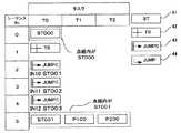
複数のロボットを制御するロボット制御装置の従来のプログラムとしては、図7に示すようなシーケンスプログラムがあった。図7の第1シーケンスプログラムにおいてその縦欄にはステップ1からステップ2,3,・・・とステップが記述され、横欄にはロボットRB1、RB2及びRB3の各々をシーケンス制御するためのR1項、R2項及びR3項が記述されている。同一行は同一ステップであり、並列して処理される。各ステップの処理は、1つ前のステップの処理が完了した後に開始される。
各R項は、F欄と、作業欄と、部品欄と、ツール欄と、場所欄とからなる。F欄は、前ステップからの継続処理の有無を表しており、例えばR3項のステップ2のF欄のように矢印が記述されている場合には、1つ前のステップ1の処理がステップ2においても継続処理されることを示す(特許文献1参照)。
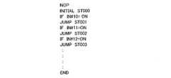
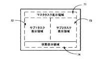
また、複数のロボット動作プログラムを表示する従来の装置について、図8〜図10を使って説明する。図8は、動作プログラム/状態表示部の表示画面の表示領域を、マスタタスク表示領域71、サブ1タスク表示領域72、サブ2タスク表示領域73、状態表示領域74に分割し、図9のフローチャートに従って同期して動く複数の動作プログラムを図10に示すように連動させながら表示する。 図10は左側に図9のフローチャートを、右側には図8のロボットの各動作プログラムによる状態表示画面を示し、図9のフローチャートにより図8の表示が制御される様子を示している。(特許文献2参照)。As a conventional program of a robot control apparatus that controls a plurality of robots, there is a sequence program as shown in FIG. In the first sequence program of FIG. 7,
Each R term includes an F column, a work column, a parts column, a tool column, and a location column. The F column indicates the presence or absence of the continuation processing from the previous step. For example, when an arrow is described as in the F column of
A conventional apparatus for displaying a plurality of robot operation programs will be described with reference to FIGS. 8 divides the display area of the display screen of the operation program / status display section into a master
特許文献1記載の発明は、ロボット毎に並列処理を行う場合に各々のロボットに対しプログラムを作成可能である点については有効である。しかしながら、複数のロボットが、ある作業単位で並列して処理を行うのか、または同期して処理を行うのかなどを操作者が総合的に判断することができない。
例えばワークに対し溶接を行う作業では、ワークをジグにセットする工程、溶接を施工する工程、ワークを反転する工程、溶接を施工する工程、次工程へワークを搬送する工程など複数の作業工程から構成されている。
特許文献1に記載の発明では、操作者は作業工程に関連して現在どの作業工程なのか、またはこの作業工程から次工程へはどのような条件で実行が遷移するのかなどについてはプログラムを見ることでしか判断することができないという問題があった。
一方、特許文献2記載の発明では、表示画面にはロボットの動作プログラムがそのまま表示されており、熟練した操作者以外には表示内容の意味が分かりづらいという問題があった。The invention described in
For example, in the work of welding to a workpiece, from the multiple work processes such as the process of setting the work on a jig, the process of performing welding, the process of reversing the work, the process of performing welding, the process of transporting the work to the next process It is configured.
In the invention described in
On the other hand, in the invention described in
本発明は、このような従来の技術が有していた問題を解決するものであり、作業工程に関連して現在どの作業工程なのか、またはこの作業工程から次工程へはどのような条件で実行が遷移するのかなどについて簡単に判断することができ、また、熟練者でなくても表示内容の意味が分かるロボットシステムを提供することを目的とする。 The present invention solves such problems of the prior art, and which work process is currently related to the work process or under what conditions from this work process to the next process. It is an object of the present invention to provide a robot system that can easily determine whether or not execution changes, and that can understand the meaning of display contents even if it is not an expert.
上記目的を達成するため、請求項1記載の発明は、ロボット制御装置に係り、複数台のロボットのうち1台以上をロボットプログラムに基づいて同時に制御するロボット制御装置であって、教示装置と接続されたロボット制御装置において、
前記複数台のロボットのうち1台以上を前記教示装置の表示手段上にて任意に組み合わせてユニットとして定義するユニット登録部と、前記教示装置の表示手段上にて、前記ユニットで定義されたロボットにより実行する作業であるタスク毎に前記タスクを実行する前記ユニットを割り当てるタスク登録部と、前記ユニットに割り当てられたタスク毎にグラフィカルなプログラムとして前記ロボットプログラムを作成するグラフィック言語処理部と、を備えることで、タスクに対応するユニット内のロボットのプログラムを、操作者が稼働状況を総合的に判断できるマトリクス状のグラフィカルなプログラムとして作成することを特徴としている。In order to achieve the above object, a first aspect of the present invention relates to a robot control apparatus, which is a robot control apparatus that simultaneously controls one or more of a plurality of robots based on a robot program, and is connected to a teaching apparatus. In the robot control device,
A unit registration unit that arbitrarily defines one or more of the plurality of robots on the display unit of the teaching device as a unit, and a robot defined by the unit on the display unit of the teaching device A task registration unit that assigns the unit that executes the task for each task that is an operation to be executed, and a graphic language processing unit that creates the robot program as a graphical program for each task assigned to the unit. Thus, the robotprogram in the unit corresponding to the task is created as amatrix-like graphical programthat allows the operator to comprehensively determine the operating status .
請求項2記載の発明は、請求項1記載のロボット制御装置において、前記グラフィック言語処理部が、前記教示装置の前記表示手段の各行に時系列に実行するシーケンス番号を表示し、各列に前記タスクにて実行する前記ロボットプログラムを前記教示装置の前記表示手段に表示させることを特徴としている。According to a second aspect of the invention, the robot control apparatus according to
請求項3記載の発明は、請求項2記載のロボット制御装置において、前記グラフィック言語処理部が、現在のステップの実行が終了した後、次のステップに実行を遷移させるようなプログラムを作成することを特徴としている。According to a third aspect of the present invention, in the robot control device according to the second aspect, the graphic language processing unitcreates a program that transitions execution to the next step after the execution of the current step is completed. It is characterized by.
請求項4記載の発明は、請求項2または3記載のロボット制御装置において、前記グラフィック言語処理部が、現在のステップの実行終了した後に、前記ロボット制御装置に対する外部からの入力信号に基づいて所定のステップに実行を遷移させるようなプログラムを作成することを特徴としている。
According to a fourth aspect of the present invention, in the robot control device according to the second or third aspect, the graphic language processing unit is predetermined based on an external input signal to the robot control device after the execution of the current step is completed. It is characterizedby creating a program that shifts execution to these steps.
請求項5記載の発明は、ロボットシステムに係り、複数台のロボットと、前記複数台のロボットのうち1台以上をロボットプログラムに基づいて同時に制御するロボット制御装置と、前記ロボット制御装置に接続され前記ロボットプログラムの表示手段および編集手段を備えたロボット教示装置と、からなるロボットシステムにおいて、前記ロボット制御装置が請求項1〜4のいずれか1項記載のロボット制御装置であることを特徴としている。 The invention according to
以上のような構成によって、本発明のロボットシステムは、特別な言語を習熟することなく複数のロボットの作業シーケンスを容易に作成できるという格段の効果をもたらすものであり、また、ロボットの作業実行中においては、実行状態をグラフィック表示することにより、操作者は現在の稼動状況を総合的に判断することができるようになる。 With the configuration as described above, the robot system of the present invention has a remarkable effect that it is possible to easily create a work sequence of a plurality of robots without learning a special language. In, by displaying the execution state in graphic form, the operator can comprehensively determine the current operation status.
以下、本発明の実施の形態として図1〜図6に基づいて説明する。 Hereinafter, an embodiment of the present invention will be described with reference to FIGS.
図1は本発明のロボットシステムの構成図である。
図1において、R1、R2、R3、R4は、関節部に電動サーボモータを備えるロボットである。ここでロボットとは、一般的にポジショナと言われているものも含む。すなわち関節駆動部を備えるものを指す。以下の実施例においては、6軸の多関節ロボットを用いた場合を想定して説明する。
ロボット制御装置10は、ロボットR1、R2、R3、R4を制御する。本実施例では4台の例で説明するが、2台以上であればよい。また、ロボット制御装置についても、本実施例では1台の例で説明するが、複数のロボット制御装置が各々ロボットを制御する構成でもよい。
ロボット制御装置10には、教示装置11が接続されている。教示装置11は、操作者が操作する各種キーと、表示画面12を備えている。表示画面12には、操作者のキー操作に基づいて、後述するグラフィカルなソフトウェアボタンが表示される。ソフトウェアボタンは操作者が現在選択できる項目を表示しており、操作者がそのボタンを選択することでそのボタンに対応した画面やメッセージが新たに表示される。
操作者は、教示装置11のキーを操作してロボットR1〜R4のうち所望するロボットを動作させ、その位置を登録することができる。また、表示画面12に表示された命令を選択または入力することにより、ロボットの動作や作業をプログラムすることができる。FIG. 1 is a configuration diagram of a robot system according to the present invention.
In FIG. 1, R1, R2, R3, and R4 are robots that include an electric servo motor at a joint. Here, the robot includes what is generally called a positioner. That is, it refers to one provided with a joint drive unit. In the following embodiments, description will be made assuming that a 6-axis articulated robot is used.
The robot control device 10 controls the robots R1, R2, R3, and R4. In the present embodiment, an example of four units will be described, but two or more units may be used. Also, the robot control device will be described as an example in this embodiment, but a configuration in which a plurality of robot control devices each control a robot may be used.
A teaching device 11 is connected to the robot control device 10. The teaching device 11 includes various keys operated by an operator and a display screen 12. The display screen 12 displays a graphical software button to be described later based on an operator's key operation. The software button displays items that can be selected by the operator, and when the operator selects the button, a screen or a message corresponding to the button is newly displayed.
The operator can operate a key of the teaching device 11 to operate a desired robot among the robots R1 to R4 and register the position thereof. Further, by selecting or inputting a command displayed on the display screen 12, the operation and work of the robot can be programmed.
教示装置11を操作して作成されたロボットプログラムは、ロボット制御装置10内の記憶部に格納される。ロボットプログラムは、教示装置11やその他の外部からの信号により実行が開始される。ロボットプログラムはロボット制御装置10内のプログラム実行部5にて実行され、サーボ制御部6にロボットの各関節のサーボモータに対する指令を出力する。各ロボットは以上の過程でロボットプログラムに基づいて制御される。 A robot program created by operating the teaching device 11 is stored in a storage unit in the robot control device 10. Execution of the robot program is started by a signal from the teaching device 11 or other external devices. The robot program is executed by the
ユニット登録部1は、複数のロボットの組み合わせをユニットとして登録する。
登録は、操作者が教示装置11のキーを操作して表示画面12に図2に示す表を表示させ、さらに教示装置11のキーを操作することで行う。
図2の例では、ユニット1(U1)にはロボットR1が、ユニット2(U2)にはロボットR2が、ユニット3(U3)にはロボットR1とロボットR2がそれぞれ登録されている。図2では、ユニットの登録数を99までとしているが、ロボット制御装置10に接続するロボットの台数や作業内容に応じて登録数を可変としてもよい。The
The registration is performed by the operator operating the keys of the teaching device 11 to display the table shown in FIG. 2 on the display screen 12 and further operating the keys of the teaching device 11.
In the example of FIG. 2, the robot R1 is registered in the unit 1 (U1), the robot R2 is registered in the unit 2 (U2), and the robot R1 and the robot R2 are registered in the unit 3 (U3). In FIG. 2, the number of registered units is 99, but the number of registered units may be variable depending on the number of robots connected to the robot control apparatus 10 and the work contents.
続いて、タスク登録部2について図3を用いて説明する。
タスク登録部2は、ユニット登録部1にて登録されたユニットとタスクの関係を登録するものである。タスクとは、ロボット制御装置10内で互いに独立して実行される作業単位である。
図3の例ではタスクはT0からT8まであり、タスク毎に、作業を行うユニットを設定できる。この設定についても、操作者が教示装置11のキーを操作して行う。タスクT2のように1つのタスクに複数のユニット(U2とU3)を割り付けることもできる。ただし、タスクT0は他のタスクを統制する特別なタスクであるため、ユニットの割り付けは行わない。Next, the
The
In the example of FIG. 3, there are tasks from T0 to T8, and a unit for performing work can be set for each task. This setting is also made by operating the keys of the teaching device 11 by the operator. A plurality of units (U2 and U3) can be assigned to one task as in task T2. However, since the task T0 is a special task that controls other tasks, no unit is assigned.
次に、グラフィック言語処理部3について説明する。
グラフィック言語処理部3は、教示装置11のキー操作により図4に示す画面を表示画面12に表示する。
図4において、列方向に並ぶT0、T1、T2は前述のタスクを表し、行方向に並ぶ0〜5はシーケンス番号を表す。シーケンス番号とはロボットプログラムを構成する最小単位の命令ごとに割り当てられる番号である。
操作者は、教示装置11のキーおよび表示画面12上のソフトウェアボタン41〜44を操作し、プログラム領域40にソフトウェアボタンや条件を配置していくことで、グラフィカルなプログラムを作成することができる。
ここで、ソフトウェアボタン41〜44について説明する。
ソフトウェアボタン41は、ステップを意味する。ステップとはユニットが行う一連の作業をまとめたもので、「ST」と数字の組み合わせによって識別される。操作者はソフトウェアボタン41を選択時に、続いて教示装置11のキーを操作してステップに割り当てる数字を入力する。なお、ステップ0(ST000)はタスクT0で実行される。
ソフトウェアボタン42は、プログラムの実行の遷移を指定する際にソフトウェアボタン43または44と組み合わせて使用する。
ソフトウェアボタン43は条件つきのジャンプ機能であり、指定された条件が成立した場合、指定されたステップへプログラムの実行を遷移させるものである。
一方、ソフトウェアボタン44は無条件のジャンプ機能であり、無条件に指定されたステップへ実行を遷移させるものである。
条件の指定はソフトウェアボタン43、44を選択時に操作者が教示装置11のキーを操作して行う。
図4に示すようにソフトウェアボタンには文字のみならずその意味に即したマークが併記されており、これにより熟練した操作者でなくともプログラムの意味や流れについて容易に理解することができる。Next, the graphic
The graphic
In FIG. 4, T0, T1, and T2 arranged in the column direction represent the tasks described above, and 0 to 5 arranged in the row direction represent sequence numbers. The sequence number is a number assigned for each instruction of the minimum unit constituting the robot program.
The operator can create a graphical program by operating the keys of the teaching device 11 and the
Here, the
The
The
The
On the other hand, the
The conditions are designated by operating the keys of the teaching device 11 by the operator when selecting the
As shown in FIG. 4, not only characters but also a mark corresponding to the meaning is written on the software button, so that even a skilled operator can easily understand the meaning and flow of the program.
図5は作成したグラフィックプログラムの一例である。
図5のシーケンス番号2を例として説明する。シーケンス番号2は条件つきジャンプであり、その下に記述されている「IN10 ST001」とは、ロボット制御装置10内の入力信号番号10番に対して外部からの信号が入信した場合に、ステップ1(ST001)へ実行を遷移させることを意味している。
シーケンス番号5の行にある通り、ST001ではタスクT1にてP100が、タスクT2にてP200が実行される。P100、P200はそれぞれロボットプログラム100、ロボットプログラム200を示す。これらのロボットプログラムはステップを構成する要素であり、ロボットの動作命令が記述されていて記憶部に格納される。
さらに、シーケンス番号3、4も同様に、外部からの信号が入信した場合にそれぞれステップ2(ST002)、ステップ3(ST003)へ実行を遷移させることを意味している。FIG. 5 shows an example of the created graphic program.
The
As shown in the row of
Similarly,
プログラム変換部4は、操作者が作成した図5のようなグラフィックプログラムをロボットプログラムに変換する。グラフィックプログラムからロボットプログラムへの変換は、教示装置11のキー操作により実行することができる。
図5に示すグラフィックプログラムのシーケンス番号0〜4の部分をロボットプログラムに変換した場合の例を図6に示す。前述のように、変換されたロボットプログラムは記憶部に格納される。
シーケンス番号0〜4ではタスクT0のみしか記述されておらず、前述のようにタスクT0は他のタスクを統率するタスクであるため、ロボットを動作させる命令は図6には含まれていない。The
FIG. 6 shows an example in which the part of
Only the task T0 is described in the
続いて、前述のようにして作成されたロボットプログラムの実行(プレイバック)について説明する。
操作者が教示装置11のキーを操作して記憶部に格納されたロボットプログラムから所望するものを選択すると、プログラム変換部4は先程とは逆にそのロボットプログラムをグラフィックプログラムへと変換し、表示画面12に表示する。
さらに、操作者が教示装置11のキーを操作することにより、選択したロボットプログラムをプレイバックさせることができる。具体的には、前述のようにロボット制御装置10内のプログラム実行部5が図6のようなロボットプログラムを解釈してサーボ制御部6に指令を出力し、各ロボットが作業を行う。
図5の例では、ステップ1(ST001)へジャンプするとタスクT1でロボットプログラム100(P100)を実行し、タスクT2でロボットプログラム200(P200)を実行するが、タスクT1にロボットR1とR2とを組み合わせたユニットを割り付け、タスクT2にロボットR3とR4とを組み合わせたユニットを割り付けた場合、ロボットプログラム100(P100)ではロボットR1、R2の2台の協調動作を実行し、ロボットプログラム200(P200)ではロボットR3、R4の2台の協調動作を実行する。この際、2つのロボットプログラムは並列に実行される。
また、プレイバック時においては、操作者が視認しやすいように表示画面12がモノクロ表示の場合にはプログラム領域40内の実行中の部分のみ反転表示にしたり、表示画面12が多色表示対応の場合にはプログラム領域40内の実行中の部分のみ色を変えたりして、プログラム内の現在の実行箇所を提示する。Next, execution (playback) of the robot program created as described above will be described.
When the operator operates the keys of the teaching device 11 and selects a desired one from the robot programs stored in the storage unit, the
Furthermore, the selected robot program can be played back by the operator operating the keys of the teaching device 11. Specifically, as described above, the
In the example of FIG. 5, when jumping to step 1 (ST001), the robot program 100 (P100) is executed at task T1 and the robot program 200 (P200) is executed at task T2. However, robots R1 and R2 are assigned to task T1. When a combined unit is assigned and a unit in which robots R3 and R4 are combined is assigned to task T2, robot program 100 (P100) executes the coordinated operation of two robots R1 and R2, and robot program 200 (P200). Then, the cooperative operation of the two robots R3 and R4 is executed. At this time, the two robot programs are executed in parallel.
Further, at the time of playback, when the display screen 12 is in monochrome display so that the operator can easily recognize it, only the currently executed portion in the
以上のように、本発明のロボットシステムによれば、特別な言語を習熟することなく複数のロボットの作業シーケンスを容易に作成できるという格段の効果をもたらすものであり、また、ロボットの作業実行中においては、実行状態をグラフィック表示することにより、操作者は現在の稼動状況を総合的に判断することができるようになるので、複数台のロボットを制御するロボットシステムであれば広く適用できるものである。 As described above, according to the robot system of the present invention, it is possible to easily create a work sequence of a plurality of robots without learning a special language. Since the operator can comprehensively determine the current operating status by displaying the execution status in a graphic, it can be widely applied to any robot system that controls multiple robots. is there.
R1、R2,R3,R4 ロボット
1 ユニット登録部
2 タスク登録部
3 グラフィック言語処理部
4 プログラム変換部
5 プログラム実行部
6 サーボ制御部
10 ロボット制御装置
11 教示装置
40 プログラム領域
41 ステップを意味するソフトウェアボタン
42 遷移を意味するソフトウェアボタン
43 条件つきジャンプを意味するソフトウェアボタン
44 無条件ジャンプを意味するソフトウェアボタン
71 マスタタスク表示領域
72 サブ1タスク表示領域
73 サブ2タスク表示領域
74 制御状態表示領域R1, R2, R3,
Claims (5)
Translated fromJapanese前記複数台のロボットのうち1台以上を前記教示装置の表示手段上にて任意に組み合わせてユニットとして定義するユニット登録部と、
前記教示装置の表示手段上にて、前記ユニットで定義されたロボットにより実行する作業であるタスク毎に前記タスクを実行する前記ユニットを割り当てるタスク登録部と、
前記ユニットに割り当てられたタスク毎にグラフィカルなプログラムとして前記ロボットプログラムを作成するグラフィック言語処理部と、を備えることで、
タスクに対応するユニット内のロボットのプログラムを、操作者が稼働状況を総合的に判断できるマトリクス状のグラフィカルなプログラムとして作成することを特徴とするロボット制御装置。A robot control device that controls one or more of a plurality of robots simultaneously based on a robot program, wherein the robot control device is connected to a teaching device.
A unit registration unit that defines one or more of the plurality of robots as a unit by arbitrarily combining them on the display unit of the teaching device;
A task registration unit that assigns the unit that executes the task for each task that is a task executed by the robot defined by the unit on the display unit of the teaching device;
A graphic language processing unit that creates the robot program as a graphical program for each task assigned to the unit,
A robot control apparatus, wherein a robotprogram in a unit corresponding to a task is created as amatrix-like graphical programthat allows an operator to comprehensively determine the operation status .
前記ロボット制御装置が請求項1〜4のいずれか1項記載のロボット制御装置であることを特徴とするロボットシステム。A robot provided with a plurality of robots, a robot control device for simultaneously controlling one or more of the plurality of robots based on a robot program, and a robot program display unit and an editing unit connected to the robot control unit In a robot system comprising a teaching device,
A robot system, wherein the robot control device is the robot control device according to any one of claims 1 to 4.
Priority Applications (6)
| Application Number | Priority Date | Filing Date | Title |
|---|---|---|---|
| JP2004319169AJP4744847B2 (en) | 2004-11-02 | 2004-11-02 | Robot control device and robot system |
| EP05805507AEP1815951B1 (en) | 2004-11-02 | 2005-11-02 | Robot controller and robot system |
| CNB2005800381695ACN100551635C (en) | 2004-11-02 | 2005-11-02 | Robot controller and robot system |
| US11/718,441US8396599B2 (en) | 2004-11-02 | 2005-11-02 | Robot control apparatus and robot system |
| ES05805507TES2380625T3 (en) | 2004-11-02 | 2005-11-02 | Robot controller and robot system |
| PCT/JP2005/020213WO2006049210A1 (en) | 2004-11-02 | 2005-11-02 | Robot controller and robot system |
Applications Claiming Priority (1)
| Application Number | Priority Date | Filing Date | Title |
|---|---|---|---|
| JP2004319169AJP4744847B2 (en) | 2004-11-02 | 2004-11-02 | Robot control device and robot system |
Publications (2)
| Publication Number | Publication Date |
|---|---|
| JP2006130577A JP2006130577A (en) | 2006-05-25 |
| JP4744847B2true JP4744847B2 (en) | 2011-08-10 |
Family
ID=36319215
Family Applications (1)
| Application Number | Title | Priority Date | Filing Date |
|---|---|---|---|
| JP2004319169AExpired - LifetimeJP4744847B2 (en) | 2004-11-02 | 2004-11-02 | Robot control device and robot system |
Country Status (6)
| Country | Link |
|---|---|
| US (1) | US8396599B2 (en) |
| EP (1) | EP1815951B1 (en) |
| JP (1) | JP4744847B2 (en) |
| CN (1) | CN100551635C (en) |
| ES (1) | ES2380625T3 (en) |
| WO (1) | WO2006049210A1 (en) |
Families Citing this family (16)
| Publication number | Priority date | Publication date | Assignee | Title |
|---|---|---|---|---|
| SG174000A1 (en) | 2004-06-24 | 2011-09-29 | Irobot Corp | Remote control scheduler and method for autonomous robotic device |
| US7706917B1 (en) | 2004-07-07 | 2010-04-27 | Irobot Corporation | Celestial navigation system for an autonomous robot |
| US11209833B2 (en) | 2004-07-07 | 2021-12-28 | Irobot Corporation | Celestial navigation system for an autonomous vehicle |
| US8972052B2 (en) | 2004-07-07 | 2015-03-03 | Irobot Corporation | Celestial navigation system for an autonomous vehicle |
| US8930023B2 (en) | 2009-11-06 | 2015-01-06 | Irobot Corporation | Localization by learning of wave-signal distributions |
| US7383100B2 (en)* | 2005-09-29 | 2008-06-03 | Honda Motor Co., Ltd. | Extensible task engine framework for humanoid robots |
| WO2009097895A1 (en)* | 2008-02-05 | 2009-08-13 | Abb Technology Ab | An industrial robot system |
| JP2010120095A (en)* | 2008-11-17 | 2010-06-03 | Yaskawa Electric Corp | Robot system |
| JP6193554B2 (en)* | 2011-11-04 | 2017-09-06 | ファナック アメリカ コーポレイション | Robot teaching apparatus having a three-dimensional display unit |
| US9008839B1 (en)* | 2012-02-07 | 2015-04-14 | Google Inc. | Systems and methods for allocating tasks to a plurality of robotic devices |
| FR2991222B1 (en)* | 2012-06-01 | 2015-02-27 | Aldebaran Robotics | SYSTEM AND METHOD FOR GENERATING CONTEXTUAL MOBILE ROBOT BEHAVIOR EXECUTED IN REAL-TIME |
| JP5862611B2 (en)* | 2013-04-02 | 2016-02-16 | トヨタ自動車株式会社 | Work change device, work change method, and work change program |
| KR101458707B1 (en)* | 2013-05-30 | 2014-11-05 | 한전케이피에스 주식회사 | System for controlling end-effector of automatic robot and method thereof |
| CN109426560A (en)* | 2017-08-28 | 2019-03-05 | 杭州海康机器人技术有限公司 | Method for allocating tasks, device and computer readable storage medium |
| JP6969283B2 (en) | 2017-10-25 | 2021-11-24 | オムロン株式会社 | Control system |
| JP7069971B2 (en)* | 2018-03-30 | 2022-05-18 | セイコーエプソン株式会社 | Controls, robots, and robot systems |
Family Cites Families (24)
| Publication number | Priority date | Publication date | Assignee | Title |
|---|---|---|---|---|
| US5260868A (en) | 1986-08-11 | 1993-11-09 | Texas Instruments Incorporate | Method for calendaring future events in real-time |
| US4896269A (en)* | 1988-02-29 | 1990-01-23 | General Electric Company | Job shop scheduling and production method and apparatus |
| CA2007140A1 (en)* | 1989-08-09 | 1991-02-09 | Toshiji Senda | Method of sequence control |
| JPH04201081A (en)* | 1990-11-29 | 1992-07-22 | Honda Motor Co Ltd | robot control device |
| US5260668A (en)* | 1992-06-11 | 1993-11-09 | Prometrix Corporation | Semiconductor surface resistivity probe with semiconductor temperature control |
| JPH0667709A (en)* | 1992-06-17 | 1994-03-11 | Fujitsu Ltd | Sequence program creating method and apparatus and sequence control apparatus |
| US5675229A (en)* | 1994-09-21 | 1997-10-07 | Abb Robotics Inc. | Apparatus and method for adjusting robot positioning |
| JPH08249026A (en)* | 1995-03-10 | 1996-09-27 | Fanuc Ltd | Programming method for system including robot |
| WO1997011416A1 (en)* | 1995-09-19 | 1997-03-27 | Kabushiki Kaisha Yaskawa Denki | Robot language processor |
| JPH09244730A (en)* | 1996-03-11 | 1997-09-19 | Komatsu Ltd | Robot system and robot controller |
| JP3427918B2 (en)* | 1996-07-02 | 2003-07-22 | インターナショナル・ビジネス・マシーンズ・コーポレーション | Program development support system and support method |
| JP3832686B2 (en) | 1997-08-08 | 2006-10-11 | 株式会社安川電機 | Robot operation program display device and control device |
| JPH11194810A (en)* | 1998-01-06 | 1999-07-21 | Okuma Corp | Nc information editing device |
| US6243857B1 (en)* | 1998-02-17 | 2001-06-05 | Nemasoft, Inc. | Windows-based flowcharting and code generation system |
| US6061602A (en)* | 1998-06-23 | 2000-05-09 | Creative Lifestyles, Inc. | Method and apparatus for developing application software for home automation system |
| US6266577B1 (en)* | 1998-07-13 | 2001-07-24 | Gte Internetworking Incorporated | System for dynamically reconfigure wireless robot network |
| DE19910311A1 (en)* | 1999-03-09 | 2000-09-14 | Siemens Ag | Automation system with reusable automation objects and process for reusing automation solutions in engineering tools |
| JP3708357B2 (en)* | 1999-04-01 | 2005-10-19 | 松下電器産業株式会社 | Robot controller |
| JP3538362B2 (en)* | 1999-09-16 | 2004-06-14 | ファナック株式会社 | Synchronous or cooperative operation control device for multiple robots |
| AT412196B (en)* | 2000-03-17 | 2004-11-25 | Keba Ag | METHOD FOR ASSIGNING A MOBILE OPERATING AND / OR OBSERVATION DEVICE TO A MACHINE AND OPERATING AND / OR OBSERVATION DEVICE THEREFOR |
| JP4592919B2 (en)* | 2000-10-26 | 2010-12-08 | シチズンホールディングス株式会社 | Automatic programming method and automatic programming apparatus |
| US6408226B1 (en)* | 2001-04-24 | 2002-06-18 | Sandia Corporation | Cooperative system and method using mobile robots for testing a cooperative search controller |
| US6975921B2 (en)* | 2001-11-09 | 2005-12-13 | Asm International Nv | Graphical representation of a wafer processing process |
| WO2004003680A2 (en)* | 2002-04-22 | 2004-01-08 | Neal Solomon | System, method and apparatus for automated collective mobile robotic vehicles used in remote sensing surveillance |
- 2004
- 2004-11-02JPJP2004319169Apatent/JP4744847B2/ennot_activeExpired - Lifetime
- 2005
- 2005-11-02ESES05805507Tpatent/ES2380625T3/enactiveActive
- 2005-11-02EPEP05805507Apatent/EP1815951B1/ennot_activeNot-in-force
- 2005-11-02CNCNB2005800381695Apatent/CN100551635C/enactiveActive
- 2005-11-02WOPCT/JP2005/020213patent/WO2006049210A1/enactiveApplication Filing
- 2005-11-02USUS11/718,441patent/US8396599B2/enactiveActive
Also Published As
| Publication number | Publication date |
|---|---|
| CN101056744A (en) | 2007-10-17 |
| EP1815951A4 (en) | 2010-11-03 |
| WO2006049210A1 (en) | 2006-05-11 |
| ES2380625T3 (en) | 2012-05-16 |
| JP2006130577A (en) | 2006-05-25 |
| CN100551635C (en) | 2009-10-21 |
| EP1815951B1 (en) | 2012-02-29 |
| US8396599B2 (en) | 2013-03-12 |
| US20080009973A1 (en) | 2008-01-10 |
| EP1815951A1 (en) | 2007-08-08 |
Similar Documents
| Publication | Publication Date | Title |
|---|---|---|
| JP4744847B2 (en) | Robot control device and robot system | |
| JP3819883B2 (en) | Robot program position correction device | |
| JP5702811B2 (en) | Operation program creation device | |
| US9643275B2 (en) | Interface of a welding power source and method for defining the same | |
| JP2020049569A (en) | Support device for creating program of robot | |
| JP5863414B2 (en) | Operating device and movable machine control system | |
| JP2019000964A (en) | Robot system for displaying speed | |
| JP2009297877A (en) | Device and method for preparing robot teaching program | |
| WO2014141314A1 (en) | Display device and programmable display device | |
| JP2011070539A (en) | Programmable controller | |
| JP6575130B2 (en) | Screen information generator | |
| JP2013226602A (en) | Industrial machine system | |
| JP6826153B2 (en) | Robot teaching device | |
| JP2015005121A (en) | Numerical control device with screen display switching function following NC program | |
| JP5888643B2 (en) | Operating device and movable machine control system | |
| JP3832686B2 (en) | Robot operation program display device and control device | |
| JPH03294906A (en) | Editing system for working program | |
| CN112975905B (en) | Support device for programming robot operations | |
| JP2005122597A (en) | NC machine tool display device | |
| JP2891366B2 (en) | Automatic welding equipment | |
| KR100755788B1 (en) | Robot Control System Using Point File | |
| JPH02306305A (en) | Method and device for generating control program | |
| JPH03201104A (en) | Control program creation device | |
| KR20230059421A (en) | Method for teaching robot and apparatus for the same | |
| JP2003295911A (en) | Creation and editing support method for sequence program |
Legal Events
| Date | Code | Title | Description |
|---|---|---|---|
| RD04 | Notification of resignation of power of attorney | Free format text:JAPANESE INTERMEDIATE CODE: A7424 Effective date:20060424 | |
| A621 | Written request for application examination | Free format text:JAPANESE INTERMEDIATE CODE: A621 Effective date:20070220 | |
| A131 | Notification of reasons for refusal | Free format text:JAPANESE INTERMEDIATE CODE: A131 Effective date:20100209 | |
| A521 | Request for written amendment filed | Free format text:JAPANESE INTERMEDIATE CODE: A523 Effective date:20100409 | |
| RD04 | Notification of resignation of power of attorney | Free format text:JAPANESE INTERMEDIATE CODE: A7424 Effective date:20100427 | |
| A131 | Notification of reasons for refusal | Free format text:JAPANESE INTERMEDIATE CODE: A131 Effective date:20100907 | |
| A521 | Request for written amendment filed | Free format text:JAPANESE INTERMEDIATE CODE: A523 Effective date:20101104 | |
| TRDD | Decision of grant or rejection written | ||
| A01 | Written decision to grant a patent or to grant a registration (utility model) | Free format text:JAPANESE INTERMEDIATE CODE: A01 Effective date:20110412 | |
| A61 | First payment of annual fees (during grant procedure) | Free format text:JAPANESE INTERMEDIATE CODE: A61 Effective date:20110511 | |
| FPAY | Renewal fee payment (event date is renewal date of database) | Free format text:PAYMENT UNTIL: 20140520 Year of fee payment:3 | |
| R150 | Certificate of patent or registration of utility model | Free format text:JAPANESE INTERMEDIATE CODE: R150 Ref document number:4744847 Country of ref document:JP Free format text:JAPANESE INTERMEDIATE CODE: R150 | |
| R250 | Receipt of annual fees | Free format text:JAPANESE INTERMEDIATE CODE: R250 | |
| R250 | Receipt of annual fees | Free format text:JAPANESE INTERMEDIATE CODE: R250 | |
| R250 | Receipt of annual fees | Free format text:JAPANESE INTERMEDIATE CODE: R250 | |
| R250 | Receipt of annual fees | Free format text:JAPANESE INTERMEDIATE CODE: R250 | |
| R250 | Receipt of annual fees | Free format text:JAPANESE INTERMEDIATE CODE: R250 | |
| R250 | Receipt of annual fees | Free format text:JAPANESE INTERMEDIATE CODE: R250 | |
| R250 | Receipt of annual fees | Free format text:JAPANESE INTERMEDIATE CODE: R250 | |
| R250 | Receipt of annual fees | Free format text:JAPANESE INTERMEDIATE CODE: R250 | |
| R250 | Receipt of annual fees | Free format text:JAPANESE INTERMEDIATE CODE: R250 | |
| R250 | Receipt of annual fees | Free format text:JAPANESE INTERMEDIATE CODE: R250 | |
| R250 | Receipt of annual fees | Free format text:JAPANESE INTERMEDIATE CODE: R250 | |
| EXPY | Cancellation because of completion of term |