JP4744516B2 - Tool kit - Google Patents
Tool kitDownload PDFInfo
- Publication number
- JP4744516B2 JP4744516B2JP2007516600AJP2007516600AJP4744516B2JP 4744516 B2JP4744516 B2JP 4744516B2JP 2007516600 AJP2007516600 AJP 2007516600AJP 2007516600 AJP2007516600 AJP 2007516600AJP 4744516 B2JP4744516 B2JP 4744516B2
- Authority
- JP
- Japan
- Prior art keywords
- tool
- kit
- holder
- manipulator
- tool holder
- Prior art date
- Legal status (The legal status is an assumption and is not a legal conclusion. Google has not performed a legal analysis and makes no representation as to the accuracy of the status listed.)
- Expired - Fee Related
Links
Images


Classifications
- A—HUMAN NECESSITIES
- A61—MEDICAL OR VETERINARY SCIENCE; HYGIENE
- A61B—DIAGNOSIS; SURGERY; IDENTIFICATION
- A61B17/00—Surgical instruments, devices or methods
- A61B17/12—Surgical instruments, devices or methods for ligaturing or otherwise compressing tubular parts of the body, e.g. blood vessels or umbilical cord
- A61B17/122—Clamps or clips, e.g. for the umbilical cord
- A61B17/1222—Packages or dispensers therefor
- A—HUMAN NECESSITIES
- A61—MEDICAL OR VETERINARY SCIENCE; HYGIENE
- A61B—DIAGNOSIS; SURGERY; IDENTIFICATION
- A61B50/00—Containers, covers, furniture or holders specially adapted for surgical or diagnostic appliances or instruments, e.g. sterile covers
- A61B50/20—Holders specially adapted for surgical or diagnostic appliances or instruments
- A—HUMAN NECESSITIES
- A61—MEDICAL OR VETERINARY SCIENCE; HYGIENE
- A61B—DIAGNOSIS; SURGERY; IDENTIFICATION
- A61B50/00—Containers, covers, furniture or holders specially adapted for surgical or diagnostic appliances or instruments, e.g. sterile covers
- A61B50/30—Containers specially adapted for packaging, protecting, dispensing, collecting or disposing of surgical or diagnostic appliances or instruments
- A—HUMAN NECESSITIES
- A61—MEDICAL OR VETERINARY SCIENCE; HYGIENE
- A61B—DIAGNOSIS; SURGERY; IDENTIFICATION
- A61B90/00—Instruments, implements or accessories specially adapted for surgery or diagnosis and not covered by any of the groups A61B1/00 - A61B50/00, e.g. for luxation treatment or for protecting wound edges
- A61B90/90—Identification means for patients or instruments, e.g. tags
- A61B90/94—Identification means for patients or instruments, e.g. tags coded with symbols, e.g. text
- A61B90/96—Identification means for patients or instruments, e.g. tags coded with symbols, e.g. text using barcodes
- A—HUMAN NECESSITIES
- A61—MEDICAL OR VETERINARY SCIENCE; HYGIENE
- A61B—DIAGNOSIS; SURGERY; IDENTIFICATION
- A61B17/00—Surgical instruments, devices or methods
- A61B17/00234—Surgical instruments, devices or methods for minimally invasive surgery
- A61B2017/00353—Surgical instruments, devices or methods for minimally invasive surgery one mechanical instrument performing multiple functions, e.g. cutting and grasping
- A—HUMAN NECESSITIES
- A61—MEDICAL OR VETERINARY SCIENCE; HYGIENE
- A61B—DIAGNOSIS; SURGERY; IDENTIFICATION
- A61B17/00—Surgical instruments, devices or methods
- A61B17/00234—Surgical instruments, devices or methods for minimally invasive surgery
- A61B2017/00362—Packages or dispensers for MIS instruments
- A—HUMAN NECESSITIES
- A61—MEDICAL OR VETERINARY SCIENCE; HYGIENE
- A61B—DIAGNOSIS; SURGERY; IDENTIFICATION
- A61B17/00—Surgical instruments, devices or methods
- A61B2017/00477—Coupling
- A—HUMAN NECESSITIES
- A61—MEDICAL OR VETERINARY SCIENCE; HYGIENE
- A61B—DIAGNOSIS; SURGERY; IDENTIFICATION
- A61B50/00—Containers, covers, furniture or holders specially adapted for surgical or diagnostic appliances or instruments, e.g. sterile covers
- A61B50/30—Containers specially adapted for packaging, protecting, dispensing, collecting or disposing of surgical or diagnostic appliances or instruments
- A61B2050/3008—Containers specially adapted for packaging, protecting, dispensing, collecting or disposing of surgical or diagnostic appliances or instruments having multiple compartments
- A—HUMAN NECESSITIES
- A61—MEDICAL OR VETERINARY SCIENCE; HYGIENE
- A61B—DIAGNOSIS; SURGERY; IDENTIFICATION
- A61B34/00—Computer-aided surgery; Manipulators or robots specially adapted for use in surgery
- A61B34/30—Surgical robots
Landscapes
- Health & Medical Sciences (AREA)
- Life Sciences & Earth Sciences (AREA)
- Surgery (AREA)
- Molecular Biology (AREA)
- General Health & Medical Sciences (AREA)
- Biomedical Technology (AREA)
- Heart & Thoracic Surgery (AREA)
- Medical Informatics (AREA)
- Nuclear Medicine, Radiotherapy & Molecular Imaging (AREA)
- Animal Behavior & Ethology (AREA)
- Engineering & Computer Science (AREA)
- Public Health (AREA)
- Veterinary Medicine (AREA)
- Reproductive Health (AREA)
- Vascular Medicine (AREA)
- Oral & Maxillofacial Surgery (AREA)
- Pathology (AREA)
- Surgical Instruments (AREA)
Description
Translated fromJapanese【技術分野】
【0001】
本発明は、手術器具一般に関する。特に、本発明は、侵襲性が最低限に抑えられた外科手術手順に使用できる用具キットに関する。
【背景技術】
【0002】
現在の腹腔鏡手術用具は、人体のある部位への接近可能性が制限されている。従来の用具は、切開をほとんど行わずに侵襲性の手術を行うことができるが、これらの用具は、たとえば人間の心臓の裏側に到達するために体内で湾曲させることはできない。
【0003】
さらに従来の用具は、用具の手術先端を操作する場合ケーブルを使用する必要がある。これらの用具は、内部構成部材の徹底的な殺菌を必要とするという欠点を有する。内部金属ケーブルの洗浄は、時間と費用のかかるプロセスとなることがある。このプロセスは、各手順の前に繰り返さなければならない。あるいは、使い捨て構成部材を使用すると経常コストが大幅に高くなることがある。
【0004】
さらに、現在の腹腔鏡手術システムは、体内で様々な機能を実行するのに使用される用具を体外で交換する必要があるため制限される。システム全体を体から取り出し、用具を体外で交換し、次にシステムを体に再挿入しなければならない。あるいは、他の手術用具が挿入される他の切開部が体に設けられる。この場合、外科手術手順はより複雑になり、患者の回復時間が長くなる。
【0005】
したがって、手術用具を体内で交換できるようにする腹腔鏡手術システムが必要である。
【0006】
用具を密閉領域内で交換できるようにする用具キットも必要である。
【発明の開示】
【0007】
本明細書では、少なくとも1つの取付け点を有するハウジングと、取付け部材を有する少なくとも1つの用具ホルダであって、取付け部材が、用具ホルダをハウジング上の取付け点に取り付けるようになっている用具ホルダと、用具ホルダに取外し可能に固定されるようになっている少なくとも1つの用具であって、概ね密閉または閉じ込められた領域内で使用できるようにマニピュレータに連結されるようにもなっている用具とを有し、用具がマニピュレータに連結されているときに、マニピュレータのオペレータが、概ね密閉または閉じ込められた領域から最初にマニピュレータを取り外すことなく連結された用具を第2の用具と交換することができ、用具を用具ホルダの内側に配置するときに、用具が適切にマニピュレータに連結されていないかぎり用具を用具ホルダから取り外すことができず、用具がマニピュレータに適切に連結されていると、用具が用具ホルダに適切に固定されていないかぎり、用具をマニピュレータから取り外すことができなくなる用具キットが開示される。
【0008】
本明細書では、開口部および開口部内の少なくとも1つの取付け点を有し、概ね円筒形の立体から成るハウジングと、取付け部材を有する少なくとも1つの用具ホルダであって、取付け部材が、用具ホルダをハウジング上の取付け点に取り付けるようになっており、用具ホルダが、用具ホルダが開口部内にあるときにハウジングの直径が大きくならないように開口部内に嵌まるようになっている用具ホルダと、用具ホルダに取外し可能に固定されるようになっている少なくとも1つの用具であって、概ね密閉または閉じ込められた領域内で使用できるようにマニピュレータに連結されるようにもなっている用具とを有し、用具がマニピュレータに連結されているときに、マニピュレータのオペレータが、概ね密閉または閉じ込められた領域から最初にマニピュレータを取り外すことなく連結された用具を第2の用具と交換することができ、用具を用具ホルダの内側に配置するときに、用具が適切にマニピュレータに連結されていないかぎり用具を用具ホルダから取り外すことができず、用具がマニピュレータに適切に連結されていると、用具が用具ホルダに適切に固定されていないかぎり、用具をマニピュレータから取り外すことができなくなる用具キットが開示される。
【0009】
さらに、本明細書では、用具を保持するように構成されたキャビティを内部に形成する本体と、本体の壁から離れた位置に設置された、キャビティ内の突起と、カムと、用具受け装置の尖叉を通過させるように構成された少なくとも1つのキー溝と、用具ホルダを用具キットに取り付ける取付け部材とを有する用具ホルダが開示される。
【0010】
さらに、本明細書では、少なくとも1つの用具と、用具を保持する手段と、用具を保持する手段を用具キットに取り付ける手段と、用具キットを用具キット受け装置に取り付ける手段とを有する用具キットが開示される。
【0011】
本明細書では、概ね密閉または閉じ込められた領域内で用具を交換する方法であって、各々が用具ホルダ内に保持された複数の用具を有する用具キットを密閉領域に挿入することと、複数の用具のうちの、第1の用具ホルダ内に保持された第1の用具にマニピュレータを取り付けることと、第1の用具を第1の用具ホルダから取り外すことと、第1の用具を操作することと、第1の用具を第1の用具ホルダ内に再配置することと、マニピュレータを、複数の用具のうちの、第2の用具ホルダ内に保持された第2の用具に取り付けることと、第2の用具を操作することとを含み、マニピュレータが、ステップb)〜f)の間は概ね密閉または閉じ込められた領域から取り出されない方法も開示される。
【発明を実施するための最良の形態】
【0012】
本開示の各態様は、密閉領域内で使用できる交換可能な用具のシステムに関する。概して、本明細書では、1つまたは2つ以上の用具が取り付けられたホルダが開示される。ホルダおよび取り付けられた用具は、密閉領域に挿入し密閉領域内で容易に操作することができるようにも構成されている。密閉領域の例には、腹腔鏡手術もしくは関節鏡手術時の患者の体内、または装置もしくは機械的対象の内部のメンテナンスもしくは修理時の装置もしくは機械的対象の内側が含まれる。
【0013】
ある実施形態では、用具は、マニピュレータ自体が用具を受け入れるように構成されたマニピュレータの遠位端に取り付けられるように構成される。マニピュレータの遠位端自体を密閉領域内に挿入することができる。マニピュレータの遠位端は、近位端、すなわち、オペレータに最も近い端部の所でオペレータによって制御することができる。密閉領域内で、オペレータは、ホルダ上の1組の用具から所望の用具を選択してマニピュレータの遠位端に取り付けることができる。オペレータが用具を所望の方法で使用した後、オペレータは使用済みの用具をホルダに戻し、ホルダから第2の用具を得て、第2の用具をマニピュレータの遠位端に取り付け、第2の用具を使用することができる。オペレータは、オペレータの必要に応じてこのプロセスを何度も繰り返し、それによって、マニピュレータを密閉領域から引き出す必要なしに使用済みの用具を密閉領域の内側で交換することができる。以下に詳細に説明するように、このシステムは、たとえば腹腔鏡手術に使用できるように構成される。各用具は、患者の体内で使用される様々な手術用具である。ホルダ内の用具は体内に挿入される。手術中に、外科医はマニピュレータまたは用具自体を体から取り出す必要なしに用具を使用し交換することができる。これは、従来の方法および装置に対する顕著な改善である。
【0014】
本明細書で使用される「マニピュレータ」は、オペレータによって使用される1組の制御部材を近位端に有し、本明細書では「用具受け装置」と呼ばれる、用具を保持し操作する手段を遠位端に有する装置を指す。これらの制御部材は、オペレータが概ね密閉または閉じ込められた領域内で用具受け装置を移動させ、必要に応じて用具を操作するのを可能にする。用具受け装置は、用具を交換可能に受け入れるようになっており、様々な異なる用具をその予定された目的に応じて動作させることができる。マニピュレータの例には、外科医によって使用できる市販の様々な腹腔鏡手術用具または関節鏡手術用具のうちのいずれか、または米国特許第6,607,475号に記載された装置が含まれる。マニピュレータの用具受け装置は、機械的装置の小さい穴や人体の小さい切開部のような小さい開口部を通して概ね密閉または閉じ込められた領域に進入するようになっている。
【0015】
本明細書では、「近位」は、装置の、密閉領域の外側の、オペレータに最も近い位置に常に位置する部分を指す。「遠位」は、密閉領域の、オペレータから最も遠い位置に挿入される端部を指す。近位端および遠位端は、流体連通、電気通信、ケーブルによる通信のように、互いに通信することが好ましい。このような通信は、このような通信に使用される回線を収納する、たとえばカテーテルやカニューレを通じて行うことができる。カテーテルまたはカニューレは、チューブまたはほぼ円筒形で中空の他の物体であることが好ましい。いくつかの実施形態では、カテーテルまたはカニューレは、近位端と遠位端との通信用の回線を収納しない。これらの実施形態では、カテーテルまたはカニューレは、実質的にカテーテルまたはカニューレの遠位端の所に配置された物体を、密閉領域内に、さらに操作できるように配置するのに使用される。
【0016】
本明細書に記載された装置の動作時には、カテーテルまたはカニューレ(以下単に「カニューレ」と呼ぶ)が、カニューレの近位端が常に密閉領域の外側に位置し、カニューレの遠位端が常に密閉領域の内部に位置するように用具が使用される、概ね密閉または閉じ込められた領域に挿入される。外科手術手順では、カニューレの近位端が常に体外に位置し、一方、カニューレの遠位端が常に体内に位置するように、カニューレが患者の体内に挿入される。これによって、オペレータ、すなわち外科医は、カニューレを使用して密閉領域、たとえば患者の体の内部に到達し、それによって「開放」外科手術手順を不要にすることができる。カニューレを挿入するのに必要な切開部は小さい切開部に過ぎず、カニューレを通じて、様々な手術器具が挿入され、外科手術手順が実行される。
【0017】
本明細書に記載された器具または用具は、マニピュレータの遠位端に多数の異なる方法で取り付けることができる。たとえば、いくつかの実施形態では、用具は磁気によって取り付けられ、他の実施形態では、用具をクリップによってマニピュレータの遠位端に留めることができる。用具の取付けについては以下に詳しく説明する。
【0018】
マニピュレータは、閉じ込められた空間内で用具を位置させ操作するのに使用され、水圧装置、空気圧装置、ロボット装置、標準的外科手術用装置、小侵襲手術(MIS)用装置、電気的装置、または機械的装置、あるいはこれらのシステムのうちの任意のシステムの組合せを有する装置であってもよい。用具を位置させ操作するのに使用できるあらゆるシステムが考えられる。
【0019】
本明細書に記載された用具および方法は、多数の異なる機能を実行する。この例には、把持装置、はさみ、外科小刀、平頭やプラス頭などのねじ回し、ドリルビット、アレンレンチを含むレンチ、はんだごて、超音波カッタ、縫合ドライバ、クリップドライバ、吸引/灌注装置、焼灼装置、針、カテーテル、組織安定装置、神経/血管ロケータ、放射線装置などとして使用される装置が含まれる。
【0020】
図1〜11を参照すると、概ね密閉または閉じ込められた領域内で用具を交換するシステムおよび方法のある実施形態が示されている。本発明の装置および方法は、密閉領域で用具を交換するのが望ましい様々な実施形態に容易に適用可能であり、本発明者によってすべてのそのような用途が考慮されている。当業者には、本明細書の開示を検討することによって、上記のような手順を実現するために本明細書に開示された装置および方法をどのように構成すればよいかが明らかになろう。
用具キット
本発明の各態様は、オペレータが、様々な異なる用具を比較的小さい開口部を通じて概ね密閉または閉じ込められた領域に挿入し、用具を使用し、必要に応じて、用具が取り付けられた用具キットまたはマニピュレータを引き出す必要なしに用具を交換し、作業の終了後、用具キットを密閉または閉じ込められた領域から引き出すのを可能にする用具キットシステムを提供する。したがって、いくつかの実施形態では、本明細書に記載された用具キットは、各々が用具ホルダ内に保持される多数の用具を有する。いくつかの用具ホルダはハウジングに取り付けられている。用具キットを概ね密閉または閉じ込められた領域に挿入する際、用具ホルダは、ハウジング内に配置され、空間効率が最大になり、用具キットを概ね密閉または閉じ込められた領域の小さい開口部に嵌めるのが可能になる。用具キットが概ね密閉または閉じ込められた領域内に入った後、オペレータは用具ホルダをピボット運動させてハウジングから離して、用具を、用具が取り付けられるマニピュレータに対して露出させることができる。オペレータが特定の用具を使い終わった後、オペレータは、用具をそのホルダに戻し、ホルダをハウジングの内側に配置して、用具キットを、小さい開口部を通して概ね密閉または閉じ込められた領域から取り出すのを可能にすることができる。
【0021】
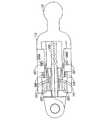
図1に示されているように、概ね密閉または閉じ込められた領域内で用具を交換するシステムの一実施形態が提供される。用具キット100は、本明細書ではホルダとも呼ばれ、遠位端104および近位端106を有するハウジング102を含んでいる。ハウジング102は、複数のホルダ110、112、114が設けられた開口部108を含んでいる。用具キット100の実施形態には、各用具キット100に1つの用具ホルダ110しか含まれない実施形態も含まれる。他の実施形態では、2つまたは3つ以上の用具ホルダ110が含まれる。図1に示されている実施形態は、3つの用具ホルダを有している。各用具ホルダ110、112、114は、後述のように用具116、118、120を含んでよい。
【0022】
用具ホルダ110、112、114は、閉じ込められた領域への用具キット100の挿入時または閉じ込められた領域からの用具キット100の取出し時にハウジング102内に嵌まり、しかもピボット運動してハウジング102から離れ、用具をマニピュレータに取り付けられるようにすることができるように構成されている。この構成では空間効率が最大になり、挿入および取出し時に用具キットを小さい開口部に容易に嵌めることができる。
【0023】
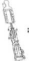
用具ホルダ110、112、114は、用具キット100上に設けられた対応する取付け点124、128、132に受け入れられる取付け部材122、126、130を含んでいる。取付け部材122、126、130と取付け点124、128、132の組合せは、用具ホルダ110、112、114が図2の114のような休止位置から外側に、図2の110のような半伸長位置、図2の112のような全伸長位置まで回転するのを可能にするヒンジを形成する。オペレータは、接近角度に基づいて、用具ホルダ110、112、114を半伸長位置、全伸長位置、または休止位置と全伸長位置との間の任意の所望の位置に回転させることができる。休止位置以外の用具ホルダ110、112、114の位置、たとえば半伸長位置や全伸長位置を本明細書では「伸長位置」と呼ぶ。
【0024】
取付け部材122、126、130を取付け点124、128、132に取り付ける方法は一般に、用具ホルダ110、112、114が休止位置から外側に伸長位置までピボット運動するのを可能にする。一実施形態では、取付け部材は、用具ホルダ110、112、114が、オペレータによってこのような伸長位置に操作された後で、ハウジング102から離れる方向に、すなわち、休止位置から伸長位置までピボット運動できるようにするのに十分な可とう性を有し、しかもオペレータが用具ホルダ110、112、114をこの伸長位置に位置させた後でハウジング102から離れた位置に保持するのに十分な剛性を有する。
【0025】
一実施態様では、取付け部材122、126、130は、取付け点124、128、132内に嵌まる概ね球形のボールであり、取付け点124、128、132は、順番に取付け部材122、126、130を受け入れる開口部を有する概ね中空の球またはソケットである。他の実施形態では、取付け部材122、126、130はピンによって取付け点124、128、132に取り付けられる。他の実施形態では、取付け部材122、126、130は、対応する穴またはくぼみ内に嵌まるかまたはスナップ嵌めされるピンを各側に有している。他の実施形態では、部材122、126、130は、円筒形や球形のピボットなどのピボットであってよい。いくつかの実施形態では、ピボットは、取外しおよび休止位置への復帰を可能にするばねピボットである。当技術分野で公知の他の取付け態様を使用することもできる。取付け点124、128、132は、取付け部材122、126、130を内部で休止および/またはピボット運動させる、ハウジング102の開口部であってよい。他の実施形態では、取付け点124、128、132は、取付け部材122、126、130がスナップ嵌め、接着、溶接、はんだ付けされるか、または他の方法で取り付けられる点であってもよい。
【0026】
用具キット100を概ね密閉または閉じ込められた領域の内部に配置するとき、用具キット100は用具キット受け装置(不図示)に取り付けられる。用具キット受け装置は、マニピュレータが導入される開口部と同じ開口部を通して概ね密閉または閉じ込められた領域に導入しても、別個の小さい開口部を通して導入してもよい。用具キット受け装置は、マニピュレータと同じであってもよい。用具キット受け装置は、木材、金属、プラスチックなどで作られたロッド、可とう性のホース、またはチューブであってよい。手術用システムでは、用具キット受け装置はカニューレであってよい。カニューレはマニピュレータの遠位端を移動させるのと同じカニューレであっても、別個のカニューレであってもよい。
【0027】
再び図1を参照すると、用具キット100は、用具キット100を用具キット受け装置に取り付ける取付け部材134をその近位端106に含んでよい。一実施形態では、取付け部材134は嵌め込み結合である。他の実施形態では、用具キット100を用具キット受け装置上にパチンと嵌めることができる。他の実施形態では、用具キット100と用具キット受け装置を磁気によって取り付けることができる。これらの実施形態の一部では、取付け部材134は、磁石であっても、電流を導入したときに磁化することのできる電磁装置であってもよい。他の実施形態では、用具キット100をピンによって用具キット受け装置に取り付けることができる。他の実施形態では、フックであっても、取付け部材134はフックを受け入れるループであってもよい。用具キット100を用具キット受け装置に取外し可能に取り付ける他の方法を使用してもよい。
【0028】
ある実施形態では、用具キット100は、カニューレの一体部分であってよい。これらの実施形態では、用具キット100は、取付け部材を含まなくてよい。さらに、これらの実施形態では、オペレータは、カニューレを密閉領域に挿入する前に用具キット100に所望の用具の配置を含めてよい。
【0029】
用具キット受け装置、たとえばカニューレは、用具キット100を概ね密閉または閉じ込められた領域内に位置させるのに使用される。いくつかの実施形態では、用具キット受け装置は、用具キット100を、概ね密閉または閉じ込められた領域内で使用する持続期間にわたって所定の位置に保持するのに使用され、この後で、用具キット受け装置が引き出される。これらの実施形態では、用具キット100は、取付け部材134を使用して、概ね密閉または閉じ込められた領域内の特徴的機能部分、たとえば、他のカニューレもしくはマニピュレータのようなこの領域内の器具の他の部分、またはこの領域内の機械の一部のような固体の物体に取り付けられる。したがって、たとえば、用具キット100は磁気的なものであってよく、その場合、用具キット100を密閉領域内に適切に配置位置された金属面に取り付けることができる。取付け部材134は、密閉または閉じ込められた領域内の所定の位置に固定することのできるフックであってもよい。マジックテープ(登録商標)、接着剤、ハンガーのような他の取付け方法も本開示の範囲内である。
【0030】
用具キット受け装置および用具キット100は、概ね密閉または閉じ込められた領域に比較的容易に挿入できるように構成されている。外科手術手順では、外科医は、用具キット受け装置および用具キット100を患者の体内に挿入することのできる小さい切開部を設けることを好む。機械装置の修理では、用具キット受け装置および用具キット100を小さい開口部を通して機械装置の内側に挿入することができる。したがって、用具キット受け装置および用具キット100のそれぞれの幅は同様であることが望ましい。この2つの構成部材の幅が同様であると、たとえば小さい切開部を通過する様々な幅の物体による患者の組織の損傷、または修復すべき器具または機械装置の損傷が防止される。
【0031】
図1に示されている実施形態を含むいくつかの好ましい実施形態では、用具キット受け装置は概ね円筒形であり、用具キット100のハウジング102は、概ね円筒形の用具キット受け装置の外径とほぼ同じ外径を有している。他の実施形態では、ハウジング102は、用具キット受け装置より小さいまたは大きい直径を有している。他の実施形態では、用具キット受け装置は円筒形ではない。用具キットの実際の寸法はその予定された用途に応じて異なってよい。用具キット受け装置および用具キット100がそれぞれの異なる直径を有するいくつかの実施形態では、2つの構成部材間の遷移領域は、より大きい直径を有する構成部材の鋭い縁部が、用具キット受け装置および用具キット100が挿入される穴の周縁に接触しないようになだらかな勾配を有しており、それによって、このような挿入が引き起こす可能性のある損傷が最低限に抑えられる。
【0032】
米国特許第6,607,475号に記載されたシステムのようないくつかの実施形態では、カニューレは流体連通に使用される配管を収納する。マニピュレータは、カニューレの端部の所に配置される。いくつかの実施形態では、用具キット100は、マニピュレータ装置が取り付けられるカニューレと同じカニューレに取り付けられる。したがって、用具キット100の各用具が取り付けられる遠位端を有するマニピュレータは、単一の入口点を介して密閉領域に導入される。これらの実施形態のうちのいくつかでは、用具キット100はカニューレ自体の一部を形成する。
【0033】
他の実施形態では、用具キット100は、マニピュレータとは異なるカニューレに取り付けられる。これらの実施形態では、用具キット100を保持するカニューレは、オペレータがマニピュレータの端部によって用具キット100内の用具に到達することのできる好都合な場所に用具キット100を配置するのに役立つ。これらの実施形態では、カニューレは流体連通配管を収納してもしなくてもよい。
【0034】
ある実施形態では、マニピュレータの遠位端は、本明細書に記載された用具を取り付けることのできる一対の尖叉またはその均等物などの用具受け装置で終わる。このような装置の例は、あらゆる図面を含む開示全体が引用によって本明細書に組み込まれる米国特許第6,607,475号に記載されている。
【0035】
いくつかの実施形態では、オペレータが概ね密閉または閉じ込められた領域の内部である用具を使用することを望むとき、オペレータは、マニピュレータおよび用具キット100をこの流体内に挿入した後、用具ホルダ110を、取付け部材122、126、130と取付け点124、128、132の組合せで形成されたヒンジの回りを、伸長位置までピボット運動させ、それによって用具ホルダ110に取り付けられた用具116を露出させることができる。この実施形態の一例が図2に示されている。第1の用具ホルダ110および第2の用具ホルダ112は、外側に伸長位置までピボット運動させられた状態で示されている。用具116を収納している第1の用具ホルダ110は、用具116を取り外しそれをマニピュレータに取り付けるようにピボット運動させられ、一方、第2の用具ホルダ112は、第2の用具を受け入れるように外側にピボット運動させられる。用具をマニピュレータに取り付け、マニピュレータから取外す方法については以下に詳しく説明する。マニピュレータに取り付けられている用具がない場合、通常、空の用具ホルダ112を外側にピボット運動させる必要がなくなることを理解されたい。さらに、用具ホルダが延ばされる角度が、マニピュレータの接近角度によって決まり、用具を用具ホルダから取り出すか、それとも用具ホルダに再配置するかによっては決まらないことを理解されたい。
【0036】
引き続き図2を参照すると、ハウジング102は、それぞれ用具ホルダ110および112がその休止位置で位置する開口部236および238を含んでよい。図2に示されている特定の実施形態では、用具ホルダ114がその休止位置に示されている。用具ホルダ110および112は、用具の交換の必要に応じて、ハウジングならびに開口部236および238から離れるように調整することができる。図2は、用具ホルダ112に設けられ用具を受け入れる開口部240を示している。
【0037】
各用具キットは、1つ、2つ、3つ、4つ、5つ、またはそれ以上の用具を含んでよい。いくつかの実施形態では、用具キットは複数の用具を有する。用具は、本明細書に記載されたように用具を用具受け装置に取り付ける取付け部材を含んでいる。各用具は、特定の用途に応じてそれぞれの異なる形状およびサイズを有してよい。いくつかの実施形態では、用具は使い捨てである。医学用とでは使い捨て用具が特に望ましい。他の実施形態では、用具を繰り返し使用することができる。これらの実施形態のうちのいくつかでは、用具を使用の合間に洗浄し、場合によっては消毒または殺菌する必要がある。
【0038】
用具キット100の他の実施形態が図3に示されている。この実施形態では、用具キット300は、各用具ホルダを密閉するハウジング102ではなく、用具ホルダ110、112、114が取り付けられたスプライン302を有している。スプライン302は、用具キット300を湾曲可能または形成可能にし、それによって、閉じ込められた領域への挿入を容易にし、かつ用具キット300の接近可能性を高め、複数の位置、特に到達するのがより困難な位置に到達できるようにする。スプライン302は、金属、プラスチック、木材、ゴムのような様々な材料で形成することができる。スプライン302に使用される特定の材料は、用具キット300が使用される特定の用途によって決定される。
【0039】
一実施形態では、概ね密閉された領域に1つの用具キットが設けられる。他の実施形態では、概ね密閉された領域に複数の用具キットが設けられる。いくつかの実施形態では、密閉領域に2つ、3つ、4つ、5つ、またはそれ以上のキットが設けられる。いくつかの実施形態では、多数の異なる用具キットを同じカニューレに取り付けることができ、一方、他の実施形態では、各カニューレに取り付けられる用具キットは1つだけである。
【0040】
図4には、用具ホルダ110の一実施形態の詳細斜視図が示されている。用具ホルダ410は開口部440を含んでいる。開口部440は、少なくともその一方の側にキー溝442を含んでよい。キー溝442は長穴444を含んでもよい。後述のように、キー溝442および長穴444を使用して各用具を用具ホルダ410の開口部440内に用具を取外し可能にロックすることができる。
【0041】
いくつかの実施形態では、用具ホルダ110、112、114は、特定の用具をしっかりと保持する形状を有し、それによって、用具が別の用具に属するホルダに挿入されるのを防止する。本明細書に記載された各用具は、用具のベース、すなわち、用具受け装置に最も近い用具の近位部が、円筒形、立方体、円錐形、円錐台形のような特定の形状を有するように構成することができる。各用具ホルダ110、112、114も、1つの用具の形状に対応する形状を有する開口部を持つように構成されている。したがって、円筒形のベースを有する用具は、円筒形の開口部を有する用具ホルダ110に嵌まる。同様に、立方体のベースを有する用具は、立方体の開口部を有する用具ホルダ110に嵌まり、他の場合も同様である。図4の開口部440は、概ね円筒形のベースを有する用具を受け入れるように概ね円筒形に示されている。
【0042】
用具ホルダ110と用具との間に1対1の関係を形成する他の手段も考えられる。いくつかの実施形態では、キー溝442の位置、たとえば、用具ホルダ410の縁部からキー溝442までの距離、あるいはキー溝442の形状および/またはサイズ、たとえばキー溝の深さや幅は、キー溝442に嵌まる用具上の構成部材の位置、形状、および/またはサイズに対応するように構成される。用具ホルダは、半剛性であることが好ましく、いくつかの実施形態では、ある程度たわみ、各用具を用具ホルダに挿入できるようにする。
用具を交換する方法
密閉領域内で用具を交換する方法について以下に説明する。この方法の各ステップについて以下に詳しく説明するが、この方法の概要は以下のとおりである。一実施形態では、オペレータが所望の用具を選択し、それを用具キット上に載せ、各用具が用具ホルダによってしっかりと保持されるようにする。次に、用具キットを密閉領域に挿入する。用具キットを密閉領域に挿入した後、オペレータは、マニピュレータを使用して、用具ホルダを外側に用具キットから離れる方向へ伸長位置まで調整することができ、これによって、オペレータは、密閉または閉じ込められた領域内で用具を容易に交換することができる。後述のように、各用具を必要に応じて用具キットの用具ホルダから取り外し用具ホルダに取り付け直すことができる。オペレータは、現在使用されている用具を、その適切な用具ホルダに挿入または配置し、用具受け装置によって他の用具ホルダから他の用具を取り出すことによって用具を交換する。用具ホルダは、密閉領域内で同じ用具キットまたは別個に設けられた用具キット上に設けることができる。
【0043】
本明細書に記載されたシステムは、用具が用具ホルダの内側に配置された後、その用具が用具受け装置によって適切に固定され保持されていないかぎり、用具ホルダから取り外せないように構成されている。さらに、用具が用具受け装置に取り付けられた後、その用具が用具ホルダに適切に挿入されないかぎり用具受け装置から取り外すことはできない。
【0044】
用具を用具受け装置に取り付けるステップ、および用具を取り外して用具ホルダに取り付けるステップの特定の実施形態について以下に詳しく説明する。図5は、用具ホルダ110の内側に保持された用具556の断面図である。この特定の実施形態では、用具556は鉗子である。しかし、本明細書に記載されたように、任意の他の種類の用具を使用することができると考えられる。突起555a、bは、用具556が用具ホルダ110内で横方向に移動するのを防止する。各用具556は、少なくとも1つの解除尖叉564を備えている。図5に示されている特定の実施形態では、用具556は2つの解除尖叉564、565を備えている。解除尖叉564、565は、用具556から湾曲した端部566a、bを有している。
【0045】
いくつかの実施形態では、解除尖叉564、565はばね状の作用を示し、したがって、解除尖叉564、565は、その休止状態、すなわち、外部の力が解除尖叉564、565にかかっていないときには、「上方」位置、すなわち、端部566a、bが用具556から離れた位置に配置される位置に位置する。解除尖叉556を用具ホルダ110の内側に配置すると、解除尖叉564、565の湾曲端部566a、bは用具ホルダ110の開口部557内に嵌まり、それによって用具556が用具ホルダ110から出入りするのを防止する。
【0046】
上述の突起555a、bと、開口部557内への解除尖叉564、565の嵌め込みとによって、用具556は常に、用具ホルダ110の内側にしっかりと配置される。
【0047】
図6は、開口部557内の解除尖叉564、565の湾曲端部566a、bを明確に示す、用具ホルダ110の内側の用具556の他の断面図である。図6に示されている実施形態のようないくつかの実施形態では、開口部557の後部、すなわち、取付け部材122から遠い端部が、前方、すなわち取付け部材122の方へ傾斜している。この傾斜と、解除尖叉564、565の湾曲端部566a、bとが相まって、さらに用具556が用具ホルダ110内にしっかりと保持される。
【0048】
用具556を用具ホルダ110から取り外すのに用具受け装置が使用される。このプロセスの実施形態が図7に示されている。この特定の用具受け装置570はその遠位端に一対の尖叉560、561を有している。いくつかの実施形態では、尖叉560、561は、米国特許第6,607,475号に記載された方法などの水圧手段によって動作させられる。尖叉560、561は、はさみ状に開閉することができる。
【0049】
各尖叉560、561は、その遠位端にかなり近い場所にピン572、573を有している。用具受け装置570に用具556を取り付ける場合、オペレータは、尖叉560、561を開き、尖叉560、561上のピン572、573を用具ホルダ110上の対応する長穴444に揃え、次に、尖叉560、561が図4に示されている用具ホルダ110のキー溝442を通して用具ホルダ110に入るように尖叉560、561を閉じる。ピン572、573および長穴444の相対的な位置決めによって、尖叉560、561は適切に用具556に揃う。図8は、尖叉のピン572、573が長穴444に適切に揃えられ、尖叉560がキー溝442を通して用具ホルダ110に入り用具556に取り付けられる準備が整うように用具ホルダ110に適切に揃えられた用具受け装置570の他の図である。
【0050】
再び図5を参照すると、用具556は、少なくとも1つであり、いくつかの実施形態では2つであり、他の実施形態では2つより多くのクリップ部材562、568を備えている。図5に示されている特定の実施形態は、用具556の各側に2つのクリップ部材、近位クリップ部材562、563および遠位クリップ部材568、569を有する用具556を示している。図5に示され、かつこの場合も図6に示されているように、2つの近位クリップ部材562、563が、1つは用具556の上方に、1つは用具556の下方に位置している。同様に、2つの遠位クリップ部材568、569が、1つは用具556の上方に、1つは用具556の下方に位置している。遠位クリップ部材568、569は後方に、すなわち解除尖叉564から離れ突起555に向かうようにカム554によって保持されている。
【0051】
尖叉560、561は、図7および8に示されているようにキー溝442を通して用具ホルダ110に入ると、近位クリップ部材562、563を解除尖叉564、565から離れ突起555に向かうように押す。図5に示されている実施形態では、近位クリップ部材562、563は頂部の所で湾曲しており、それによって、尖叉560、561は容易に下方に滑り、クリップ部材562を押し出すことができる。尖叉560上のピン572、573は2つのクリップ部材562、568間に嵌まる。尖叉がばね状の作用によって完全に閉じると、近位クリップ部材562がその最初の位置に戻り、それによって、工具556が尖叉560、561に保持される。同時に、解除尖叉564、565が、用具556と同一平面を形成するように、すなわち、尖叉560、561と用具556との間の位置に押される。したがって、解除尖叉564の湾曲端部566はもはや開口部557の内部には位置していない。オペレータは次に、マニピュレータの遠位端を引き込むことによって用具556を用具ホルダ110から取り外すことができる。
【0052】
図9は、尖叉560、561が閉位置にあり、用具556を用具ホルダ110から取り出す準備が整っている実施形態を示している。この図に示されているように、解除尖叉564、565はその引込み位置にあり、すなわち、尖叉560、561と用具556との間にしっかりと保持されており、湾曲端部566a、bは開口部557の外側に位置している。オペレータは次に、用具受け装置570を近位方向に引き戻し、用具556を用具ホルダ110から取り外す。用具が用具ホルダ110から出ると、遠位クリップ部材568、569が、カム554から取り外され、かつばね状の作用によってその休止位置に戻り、さらに用具556を尖叉560、561に固定する。図5および11に示されているように、遠位クリップ部材568、569は、頂部の所で尖叉560、561から離れる方向に湾曲している近位クリップ部材562、563とは異なり、頂部の所で尖叉560、561の方へ湾曲している。これらの特定の実施形態における遠位クリップ部材568、569の湾曲によって、尖叉560、561と用具556をよりしっかりと保持することができる。
【0053】
図5〜9が断面図であることに留意されたい。不図示の側にも対応するクリップ部材がある。すべてのクリップ部材の作用の最終的な結果として、用具556は尖叉560、561に対して横方向に移動できなくなる。さらに、ピン572、573が近位クリップ部材と遠位クリップ部材との間に嵌まるため、用具556が尖叉560、561に対して前後に移動するのも防止される。したがって、用具556は尖叉560、561にしっかりと取り付けられている。
【0054】
オペレータが必要に応じて用具を使用した後、オペレータは用具を別の用具と交換することを望む場合がある。オペレータはこの場合、現在用具受け装置に取り付けられている用具を用具ホルダに戻し、尖叉を解除し、別の用具ホルダから別の用具を得る。
【0055】
一実施形態では、図10に示されているように、用具556を用具ホルダ110に戻す場合、オペレータは尖叉560、561を閉じ、用具556を用具ホルダ110に揃え、次に用具556を遠位方向に移動させて用具556を用具ホルダ110の内側に挿入する。図9に示されているように、カム554が用具ホルダ110内の特定の深さに配置され、したがって、カムは尖叉560、561を、尖叉を開きピン572、573を長穴544を通して取り外すのに適切な場所に停止させる。
【0056】
いくつかの実施形態では、図11に示されているように、カム554は湾曲した縁部を有している。用具556を用具ホルダ110の内側に配置して前方に遠位方向へ押すと、遠位クリップ部材564、569がカム554の湾曲した縁部に接触する。用具556を用具ホルダ110の内側でさらに押すと、カム554の湾曲した縁部が遠位クリップ部材564、569を後方に、すなわち、尖叉560、561から離れる方向に移動させる。用具556を用具ホルダ110内でできるだけ遠くまで押し戻す。次に、遠位クリップ部材564、569を完全に尖叉560、561から引き離す。
【0057】
この点で、用具556を尖叉560、561に保持している力は、近位クリップ部材562、563の圧力だけである。図5を見ると分かるように、近位クリップ部材562、563の内面は、尖叉560、561から離れて突起555a、bに向かうようにわずかに湾曲している。オペレータが尖叉560、561を開いた後、最終的に尖叉560、561が近位クリップ部材562、563から出るまで、近位クリップ部材562、563は尖叉560、561から離れる方向に押される。ばね状の動作によって尖叉560が用具556から離れるにつれて、解除尖叉564、565が解除されてその休止位置に戻り、その湾曲端部566を開口部557に進入させ、それによって用具556を用具ホルダ110内にしっかりと保持する。
【0058】
図5や11などの図に示されているように、用具ホルダ110は、用具ホルダ110の壁および突起555によって形成される形作られた溝を含んでいる。この流路の厚さ、すなわち、突起555と用具ホルダ110の壁との間の距離は、特定の用具556が特定の用具ホルダ110にのみ嵌まることができるように構成することができる。この特徴は、オペレータが、特定の用具キット内の各用具の位置を記憶またはラベル付けすることができ、装置の動作中にラベルも相対位置も変更されることがないという追加的な利点を有する。
【0059】
他の実施形態では、用具556を磁力によって用具ホルダ110内にしっかりと保持する。これらの実施形態では、電気を使用することによって各用具ホルダ110を磁化することができる。用具ホルダ110を磁化した後、用具556を用具ホルダ110から取り外すことはできなくなる。オペレータが尖叉560、561を用具556上にスナップ嵌めした後、オペレータは特定の用具ホルダ110への電流を解放し、それによってこの用具ホルダ110を磁気的に中立にすることができる。この時点で、工具556を、マニピュレータに引き戻すことによって用具ホルダ110から取り外すことができる。いくつかの実施形態では、クリップ部材の1つのような用具556上のスナップは、スイッチとして働くことができ、したがって、尖叉560、561が所定の位置に嵌まると、このスイッチがオフになり、用具ホルダ110の磁化が終了する。他の実施形態では、オペレータのコマンドによって尖叉560、561を磁化または消磁することもできる。したがって、尖叉560、561を用具556上にスナップ嵌めした後、オペレータは、用具ホルダ110を消磁し、同時に尖叉560、561を磁化することができる。したがって、用具556を用具ホルダ110から取り外して尖叉560、561に取り付けることができる。
【0060】
他の実施形態では、用具556を摩擦によって用具ホルダ110内に保持する。用具556と用具ホルダ110の両方の溝が十分な摩擦を生じさせ、したがって、用具556がガタついて用具ホルダ110から外れることがなくなる。しかし、摩擦の量は、尖叉560、561が所定の位置にスナップ嵌めされた後マニピュレータが用具556を用具ホルダ110から取り外せるほど少ない。
手術用途
特に好ましい一実施形態では、用具キットがロボット手術システムと一緒に使用される。用具キットと一緒に使用できるロボット手術システムの一例が、引用によって本明細書に組み込まれる米国特許第6,607,475号に開示されている。
【0061】
用具を交換するシステムが人体に使用されるこのような実施形態では、用具キットが、複数のアームを有する手術器具と一緒に使用される。いくつかの実施形態では、用具キットを手術器具のアームのうちの少なくとも1つに取外し可能にまたは永久的に取り付けることができる。一実施形態では、用具キットは連接装置の端部に配置される。
【0062】
手術器具のアームを、患者の体に形成された小さい開口部を通して密閉領域に挿入する。次に、用具キットを密閉領域内に位置させ、手術器具のアームを調整することによって位置を調整する。手術器具の他のアームは、用具キットを使用して用具を交換することができ、したがって、密閉領域内で複数の外科的治療を行うことができる。
【0063】
手術器具と一緒に使用できる交換可能な用具には、洗浄用具、焼灼部材、リード線、カメラ、接着剤塗布用具、小形X線装置、光源のような、患者を治療するための多数の用具を含めることができるが、これらに限らない。いくつかの実施形態では、用具は、把持装置、はさみ、外科小刀、光学部材、鉗子、マーカなどである。いくつかの実施形態では、用具は、超音波カッタ、縫合ドライバ、クリップドライバ、吸引/灌注装置、焼灼装置、針、カテーテル、組織安定化装置、神経/血管ロケータ、放射線装置などである。
他の実施形態
いくつかの実施形態では、用具キット内の特定の用具を識別するシステムが設けられる(不図示)。いくつかの実施形態では、この識別システムはカラーシステムを有する。たとえば、用具ホルダは特定の色であってよい。他の場合、用具も色付けされ、用具ホルダの色と用具の色が一致する。あるいは、語、数および/または形状などを用具ホルダまたは用具キットに刻印付けして用具ホルダ内の用具の位置を特定することができる。
【0064】
ある実施形態では、用具キット100は、用具ホルダ110、112、114を覆うカバーを有する。いくつかの例では、密閉領域または閉じ込められた領域への用具キット100の挿入時あるいは密閉領域または閉じ込められた領域からの用具キット100の取出し時に、用具ホルダ110、112、114をカバーしておくと有用である。露出された用具ホルダ110、112、114は鋭い縁部を有することがある。さらに、用具ホルダ110、112、114が露出されると、用具キット100の周囲が変化する。このような変動および/または鋭い縁部は、用具キット100を密閉または閉じ込められた領域に挿入するかまたはそこから取り出すための小さい開口部に損傷、たとえば裂傷や切り傷を生じさせることがある。カバーを利用することによって、用具キット100は一様で平滑な外側層を有するようになり、密閉または閉じ込められた領域からの用具キット100の取出しおよび閉じ込められた領域自体内への用具キット100の挿入が容易になる。
【0065】
いくつかの実施形態では、カバーは用具キット100に沿って長手方向に滑り、内部に保持された用具ホルダ110、112、114を露出させることができる。他の実施形態では、カバーは、用具キット100の一方の側に1つまたは2つ以上ヒンジによって取り付けられ、たとえば、オペレータがマニピュレータを操作することによって移動させ、ヒンジに沿って開位置へ回転させることができる。
【0066】
これらの実施形態のうちのいくつかでは、カバーはラッチによって閉位置に保持される。オペレータは、カバーを開く前にまずラッチを解除する。ラッチはさらに、密閉または閉じ込められた領域に用具キット100を挿入するかまたは密閉または閉じ込められた領域から用具キット100を取り出す間にカバーを誤って開けてしまうのを防止する働きをする。他の実施形態では、ばね状の作用によってラッチが開かれた後、カバーが自動的に開位置まで移動し、それによって用具ホルダ110、112、114を露出させる。用具キット100の使用が終了した後、オペレータは、たとえばマニピュレータを使用することによってカバーを閉じ、カバーを閉位置に固定することができる。
【0067】
他のいくつかの実施形態では、カバーは、たとえば、カニューレを通して用具キット100に送信される電気信号や、密閉領域の外側のどこかから放出される無線周波数波などによって、カバーを開閉動作させるのに必要な信号をカバー内のモータに送る遠隔制御装置を使用することによって、閉位置から開位置に、かつ開位置から閉位置に移動させられる。
【0068】
ある実施形態では、1つの用具キット100が概ね密閉または閉じ込められた領域内に存在し、一方、他の実施形態では、2つまたは3つ以上の用具キット100が概ね密閉または閉じ込められた領域内に存在する。1つまたは2つ以上のマニピュレータが概ね密閉または閉じ込められた領域内に存在することができ、各マニピュレータは各用具キット100に接近することができる。
【0069】
本発明の特定の形態について説明したが、本発明の要旨および範囲から逸脱せずに様々な修正を施せることが明らかになろう。したがって、本発明は、添付の特許請求の範囲による制限を除いて制限されるものではない。
【図面の簡単な説明】
【0070】
【図1】本発明の一実施形態による用具キットの斜視図である。
【図2】用具ホルダが外側にピボット運動させられる用具キットの斜視図である。
【図3】本発明の一実施形態による用具キットの他の実施形態の斜視図である。
【図4】用具ホルダの詳細斜視図である。
【図5】用具ホルダの内側に保持された用具の断面図である。
【図6】用具ホルダの内側に保持された用具の他の断面図である。
【図7】用具ホルダから用具を取り外す直前の用具受け装置を示す図である。
【図8】用具に取り付けられる用具ホルダの前に配置された用具受け装置の他の図である。
【図9】尖叉が閉鎖され、用具を用具ホルダから出す準備が整った実施形態を示す図である。
【図10】用具がマニピュレータの尖叉に取り付けられ、用具ホルダから取り外された実施形態を示す図である。
【図11】内側に用具が保持された用具ホルダの断面図である。【Technical field】
[0001]
The present invention relates generally to surgical instruments. In particular, the present invention relates to a tool kit that can be used in surgical procedures with minimal invasiveness.
[Background]
[0002]
Current laparoscopic surgical tools have limited accessibility to certain parts of the human body. Conventional tools can perform invasive surgery with few incisions, but these tools cannot be curved in the body, for example, to reach the back of a human heart.
[0003]
Furthermore, conventional tools require the use of a cable when operating the surgical tip of the tool. These tools have the disadvantage of requiring thorough sterilization of the internal components. Cleaning the internal metal cable can be a time consuming and expensive process. This process must be repeated before each procedure. Alternatively, the use of disposable components can significantly increase the recurring cost.
[0004]
In addition, current laparoscopic surgical systems are limited because the tools used to perform various functions in the body need to be exchanged outside the body. The entire system must be removed from the body, the equipment replaced outside the body, and then the system reinserted into the body. Alternatively, another incision portion into which another surgical tool is inserted is provided in the body. In this case, the surgical procedure becomes more complex and patient recovery time increases.
[0005]
Therefore, there is a need for a laparoscopic surgery system that allows surgical tools to be exchanged within the body.
[0006]
There is also a need for a tool kit that allows the tool to be replaced in a sealed area.
DISCLOSURE OF THE INVENTION
[0007]
A housing having at least one attachment point and at least one tool holder having an attachment member, wherein the attachment member is adapted to attach the tool holder to an attachment point on the housing. At least one tool adapted to be removably secured to the tool holder, the tool also adapted to be coupled to a manipulator for use in a generally sealed or confined area. And when the tool is coupled to the manipulator, the operator of the manipulator can replace the coupled tool with the second tool without first removing the manipulator from the generally sealed or confined area; When placing the tool inside the tool holder, the tool is properly connected to the manipulator. Can not be removed tool unless not from tool holder, the tool is properly connected to a manipulator, as long as the equipment is not properly secured to the tool holder, tools andmanipulatorDisclosed is a tool kit that cannot be removed from.
[0008]
According to the present description, there is provided at least one tool holder having an opening and at least one attachment point in the opening and having a generally cylindrical solid body and an attachment member, the attachment member comprising: A tool holder adapted to be mounted at a mounting point on the housing, wherein the tool holder is adapted to fit within the opening so that the diameter of the housing does not increase when the tool holder is in the opening; At least one tool adapted to be removably secured to a manipulator for use in a generally sealed or confined area; When the tool is connected to the manipulator, the operator of the manipulator The connected tool can be replaced with a second tool without first removing the manipulator, and when the tool is placed inside the tool holder, the tool is held in the tool holder unless the tool is properly connected to the manipulator. If the tool is properly connected to the manipulator, it can be removed from the tool holder unless it is properly secured to the tool holder.manipulatorDisclosed is a tool kit that cannot be removed from.
[0009]
Furthermore, in the present specification, a body that forms a cavity configured to hold a tool therein, a protrusion in the cavity that is disposed at a position away from the wall of the body, a cam, and a tool receiving device A tool holder is disclosed having at least one keyway configured to pass through the tines and an attachment member for attaching the tool holder to the tool kit.
[0010]
Further disclosed herein is a tool kit having at least one tool, means for holding the tool, means for attaching the tool holding means to the tool kit, and means for attaching the tool kit to the tool kit receiving device. Is done.
[0011]
In this specification, there is a method for exchanging a tool in a generally sealed or confined area, wherein a tool kit having a plurality of tools each held in a tool holder is inserted into the sealed area; Of the tools, attaching a manipulator to the first tool held in the first tool holder, removing the first tool from the first tool holder, and operating the first tool Repositioning the first tool in the first tool holder; attaching the manipulator to a second tool held in the second tool holder of the plurality of tools; A method in which the manipulator is not removed from the generally sealed or confined area during steps b) -f).
BEST MODE FOR CARRYING OUT THE INVENTION
[0012]
Each aspect of the present disclosure relates to a replaceable device system that can be used in a sealed area. In general, disclosed herein is a holder having one or more tools attached thereto. The holder and the attached tool are also configured to be inserted into the sealed area and easily operated in the sealed area. Examples of sealed areas include the patient's body during laparoscopic or arthroscopic surgery, or the inside of a device or mechanical object during maintenance or repair of the device or mechanical object.
[0013]
In certain embodiments, the device is configured to be attached to the distal end of a manipulator that is itself configured to receive the device. The distal end of the manipulator itself can be inserted into the sealed area. The distal end of the manipulator can be controlled by the operator at the proximal end, ie the end closest to the operator. Within the sealed area, the operator can select the desired tool from a set of tools on the holder and attach it to the distal end of the manipulator. After the operator has used the tool in the desired manner, the operator returns the used tool to the holder, gets the second tool from the holder, attaches the second tool to the distal end of the manipulator, Can be used. The operator can repeat this process as many times as the operator needs so that used equipment can be replaced inside the sealed area without having to pull the manipulator out of the sealed area. As described in detail below, the system is configured for use in, for example, laparoscopic surgery. Each tool is a variety of surgical tools used in the patient's body. The tool in the holder is inserted into the body. During surgery, the surgeon can use and replace the device without having to remove the manipulator or the device itself from the body. This is a significant improvement over conventional methods and devices.
[0014]
As used herein, a “manipulator” has a set of control members used by an operator at a proximal end and refers to a means for holding and manipulating a tool, referred to herein as a “tool receiver”. Refers to the device at the distal end. These control members allow the operator to move the tool receiving device within a generally sealed or confined area and manipulate the tool as needed. The tool receiving device is adapted to receive a tool in a replaceable manner, and can operate a variety of different tools according to their intended purpose. Examples of manipulators include any of a variety of commercially available laparoscopic or arthroscopic surgical tools that can be used by a surgeon, or the device described in US Pat. No. 6,607,475. The manipulator device receiving device is adapted to enter a generally sealed or confined area through a small opening, such as a small hole in a mechanical device or a small incision in the human body.
[0015]
As used herein, “proximal” refers to the portion of the device that is always located outside the sealed area and closest to the operator. “Distal” refers to the end of the sealed region that is inserted farthest from the operator. The proximal and distal ends are preferably in communication with each other, such as fluid communication, telecommunications, and cable communication. Such communication can be performed, for example, through a catheter or cannula that houses the line used for such communication. The catheter or cannula is preferably a tube or other object that is generally cylindrical and hollow. In some embodiments, the catheter or cannula does not contain a communication line between the proximal and distal ends. In these embodiments, the catheter or cannula is used to place an object disposed substantially at the distal end of the catheter or cannula within the sealed region for further manipulation.
[0016]
In operation of the device described herein, a catheter or cannula (hereinafter simply referred to as a “cannula”) is such that the proximal end of the cannula is always outside the sealed region and the distal end of the cannula is always sealed. Is inserted into a generally sealed or confined area where the tool is used to be located inside. In a surgical procedure, the cannula is inserted into the patient's body so that the proximal end of the cannula is always located outside the body, while the distal end of the cannula is always located in the body. This allows an operator, or surgeon, to use a cannula to reach a sealed area, such as the interior of a patient's body, thereby eliminating the need for “open” surgical procedures. The incision required to insert the cannula is only a small incision through which various surgical instruments are inserted and the surgical procedure is performed.
[0017]
The instrument or tool described herein can be attached to the distal end of the manipulator in a number of different ways. For example, in some embodiments, the device is magnetically attached, and in other embodiments, the device can be clipped to the distal end of the manipulator. The mounting of the tool will be described in detail below.
[0018]
A manipulator is used to position and manipulate a tool in a confined space, a hydraulic device, a pneumatic device, a robotic device, a standard surgical device, a minimally invasive surgical (MIS) device, an electrical device, or It may be a mechanical device or a device having any combination of these systems. Any system that can be used to position and operate the tool is contemplated.
[0019]
The tools and methods described herein perform a number of different functions. Examples include grasping devices, scissors, surgical knives, screwdrivers such as flat and plus heads, drill bits, wrenches including allen wrenches, soldering irons, ultrasonic cutters, suture drivers, clip drivers, suction / irrigation devices, Devices used as ablation devices, needles, catheters, tissue stabilization devices, nerve / blood vessel locators, radiation devices and the like are included.
[0020]
With reference to FIGS. 1-11, one embodiment of a system and method for exchanging tools within a generally enclosed or confined area is shown. The apparatus and method of the present invention are readily applicable to various embodiments in which it is desirable to change the tool in a sealed area, and all such uses are contemplated by the inventor. It will be clear to those skilled in the art, after reviewing the disclosure herein, how the apparatus and methods disclosed herein may be configured to implement the procedures described above.
Tool kit
Each aspect of the present invention is a tool kit in which an operator inserts a variety of different tools into a generally sealed or confined area through a relatively small opening, uses the tools, and if necessary, has a tool kit or A tool kit system is provided that allows a tool to be changed without the need to pull out the manipulator and the tool kit to be pulled out of the sealed or confined area after completion of the operation. Thus, in some embodiments, the device kit described herein has a number of devices each retained within a device holder. Some tool holders are attached to the housing. When inserting the tool kit into a generally sealed or confined area, the tool holder is positioned within the housing to maximize space efficiency and fit the tool kit into a small opening in the generally sealed or confined area. It becomes possible. After the tool kit enters a generally sealed or confined area, the operator can pivot the tool holder away from the housing to expose the tool to the manipulator to which the tool is attached. After the operator has finished using a particular tool, the operator can return the tool to its holder and place the holder inside the housing to remove the tool kit from a generally sealed or confined area through a small opening. Can be possible.
[0021]
As shown in FIG. 1, one embodiment of a system for exchanging devices within a generally sealed or confined area is provided. The
[0022]
The
[0023]
The
[0024]
The method of attaching the
[0025]
In one embodiment, the
[0026]
When placing the
[0027]
Referring again to FIG. 1, the
[0028]
In certain embodiments, the
[0029]
A tool kit receiver, such as a cannula, is used to position the
[0030]
The tool kit receiving device and the
[0031]
In some preferred embodiments, including the embodiment shown in FIG. 1, the tool kit receiver is generally cylindrical, and the
[0032]
In some embodiments, such as the system described in US Pat. No. 6,607,475, the cannula houses tubing used for fluid communication. The manipulator is placed at the end of the cannula. In some embodiments, the
[0033]
In other embodiments, the
[0034]
In certain embodiments, the distal end of the manipulator ends with a device receiving device, such as a pair of tines or the like, to which the devices described herein can be attached. An example of such a device is described in US Pat. No. 6,607,475, the entire disclosure including any drawings, incorporated herein by reference.
[0035]
In some embodiments, when the operator desires to use a tool that is generally within a sealed or confined area, the operator inserts the
[0036]
With continued reference to FIG. 2, the
[0037]
Each device kit may include one, two, three, four, five, or more devices. In some embodiments, the tool kit has a plurality of tools. The tool includes a mounting member that attaches the tool to the tool receiver as described herein. Each device may have a different shape and size depending on the particular application. In some embodiments, the device is disposable. Disposable devices are particularly desirable for medical use. In other embodiments, the device can be used repeatedly. In some of these embodiments, the device needs to be cleaned between uses and possibly disinfected or sterilized.
[0038]
Another embodiment of the
[0039]
In one embodiment, one tool kit is provided in a generally sealed area. In other embodiments, a plurality of tool kits are provided in a generally sealed area. In some embodiments, two, three, four, five, or more kits are provided in the sealed area. In some embodiments, many different tool kits can be attached to the same cannula, while in other embodiments, only one tool kit can be attached to each cannula.
[0040]
A detailed perspective view of one embodiment of the
[0041]
In some embodiments, the
[0042]
Other means of creating a one-to-one relationship between the
How to change tools
A method for exchanging the tool in the sealed area will be described below. The steps of this method will be described in detail below. The outline of this method is as follows. In one embodiment, the operator selects the desired tool and places it on the tool kit so that each tool is securely held by the tool holder. Next, the tool kit is inserted into the sealed area. After inserting the tool kit into the sealed area, the operator can use the manipulator to adjust the tool holder outwardly to the extended position away from the tool kit, thereby allowing the operator to be sealed or confined. Tools can be easily changed in the area. As described below, each tool can be reattached from the tool holder of the tool kit to the removal tool holder as needed. The operator replaces the tool by inserting or placing the tool currently in use in its appropriate tool holder and removing the other tool from the other tool holder by the tool receiving device. The tool holder can be provided on the same tool kit or on a separately provided tool kit within the sealed area.
[0043]
The system described herein is configured such that after the tool is placed inside the tool holder, it cannot be removed from the tool holder unless the tool is properly secured and held by the tool receiver. . Furthermore, after the tool is attached to the tool receiver, it cannot be removed from the tool receiver unless the tool is properly inserted into the tool holder.
[0044]
Specific embodiments of attaching the tool to the tool receiving device and removing the tool and attaching it to the tool holder are described in detail below. FIG. 5 is a cross-sectional view of
[0045]
In some embodiments, the
[0046]
The
[0047]
6 is another cross-sectional view of the
[0048]
A tool receiver is used to remove
[0049]
Each
[0050]
Referring again to FIG. 5, there are at least one
[0051]
When the
[0052]
FIG. 9 shows an embodiment where the
[0053]
Note that FIGS. 5-9 are cross-sectional views. There is also a corresponding clip member on the side not shown. The net result of the action of all clip members is that the
[0054]
After the operator uses the tool as needed, the operator may desire to replace the tool with another tool. In this case, the operator returns the tool currently attached to the tool receiving device to the tool holder, releases the tines, and obtains another tool from another tool holder.
[0055]
In one embodiment, as shown in FIG. 10, when the
[0056]
In some embodiments, the
[0057]
In this regard, the only force holding the
[0058]
As shown in figures such as FIGS. 5 and 11, the
[0059]
In other embodiments, the
[0060]
In other embodiments, the
Surgical use
In one particularly preferred embodiment, a tool kit is used with a robotic surgical system. An example of a robotic surgical system that can be used with a tool kit is disclosed in US Pat. No. 6,607,475, incorporated herein by reference.
[0061]
In such embodiments where a device changing system is used on the human body, a tool kit is used with a surgical instrument having a plurality of arms. In some embodiments, the tool kit can be removably or permanently attached to at least one of the surgical instrument arms. In one embodiment, the tool kit is located at the end of the articulating device.
[0062]
The arm of the surgical instrument is inserted into the sealed area through a small opening formed in the patient's body. The tool kit is then positioned within the sealed area and adjusted in position by adjusting the arm of the surgical instrument. The other arm of the surgical instrument can replace the tool using a tool kit and thus perform multiple surgical treatments within the sealed area.
[0063]
Replaceable tools that can be used with surgical instruments include a number of tools for treating patients, such as cleaning tools, cautery members, leads, cameras, adhesive applicators, small x-ray devices, and light sources. It can be included, but is not limited to these. In some embodiments, the tool is a grasping device, scissors, surgical knife, optical member, forceps, marker, and the like. In some embodiments, the tool is an ultrasonic cutter, suture driver, clip driver, suction / irrigation device, ablation device, needle, catheter, tissue stabilization device, nerve / vascular locator, radiation device, and the like.
Other embodiments
In some embodiments, a system is provided (not shown) that identifies a particular device within the device kit. In some embodiments, the identification system has a color system. For example, the tool holder may be a specific color. In other cases, the tool is also colored so that the color of the tool holder matches the color of the tool. Alternatively, words, numbers, and / or shapes, etc. can be imprinted on the tool holder or tool kit to determine the position of the tool within the tool holder.
[0064]
In some embodiments, the
[0065]
In some embodiments, the cover can slide longitudinally along the
[0066]
In some of these embodiments, the cover is held in the closed position by a latch. The operator first releases the latch before opening the cover. The latch further serves to prevent accidental opening of the cover while the
[0067]
In some other embodiments, the cover can be opened and closed by, for example, an electrical signal transmitted to the
[0068]
In some embodiments, one
[0069]
While particular forms of the invention have been described, it will be apparent that various modifications can be made without departing from the spirit and scope of the invention. Accordingly, the invention is not limited except as by the appended claims.
[Brief description of the drawings]
[0070]
FIG. 1 is a perspective view of a device kit according to an embodiment of the present invention.
[Figure 2]Tool holderFIG. 3 is a perspective view of a tool kit that is pivoted outward.
FIG. 3 is a perspective view of another embodiment of a tool kit according to an embodiment of the present invention.
FIG. 4 is a detailed perspective view of the tool holder.
FIG. 5 is a cross-sectional view of the tool held inside the tool holder.
FIG. 6 is another cross-sectional view of the tool held inside the tool holder.
FIG. 7 is a view showing a tool receiving device immediately before the tool is removed from the tool holder.
FIG. 8 is another view of the tool receiving device disposed in front of the tool holder attached to the tool.
FIG. 9 shows an embodiment in which the tines are closed and the tool is ready to be removed from the tool holder.
FIG. 10 shows an embodiment in which the tool is attached to the manipulator tines and removed from the tool holder.
FIG. 11 is a cross-sectional view of a tool holder with a tool held inside.
Claims (23)
Translated fromJapanese少なくとも1つの取付け点を有するハウジングと、
取付け部材を有する少なくとも1つの用具ホルダであって、前記取付け部材が、前記用具ホルダを前記ハウジング上の前記取付け点に取り付けるようになっている用具ホルダと、
前記用具ホルダに取外し可能に固定されるようになっている少なくとも1つの用具であって、概ね密閉または閉じ込められた領域内で使用できるようにマニピュレータに連結されるようにもなっている用具と、
を有し、
前記用具が前記マニピュレータに連結されているときに、前記マニピュレータのオペレータが、前記概ね密閉または閉じ込められた領域から最初に前記マニピュレータを取り外すことなく前記連結された用具を第2の用具と交換することができ、
前記用具が前記用具ホルダの内側に配置されているときに、前記用具が適切に前記マニピュレータに連結されていないかぎり前記用具を前記用具ホルダから取り外すことができず、前記用具を前記マニピュレータに適切に連結すると、前記用具が前記用具ホルダに適切に固定されていないかぎり、前記用具を前記マニピュレータから取り外すことができなくなる、
用具キット。A tool kit,
A housing having at least one attachment point;
At least one tool holder having an attachment member, wherein the attachment member is adapted to attach the tool holder to the attachment point on the housing;
At least one device adapted to be removably secured to the device holder, wherein the device is also coupled to a manipulator for use in a generally sealed or confined area;
Have
When the tool is connected to the manipulator, the operator of the manipulator replaces the connected tool with a second tool without first removing the manipulator from the generally sealed or confined area. Can
When the tool is placed inside the tool holder, the tool cannot be removed from the tool holder unless the tool is properly connected to the manipulator, and the tool is properly attached to the manipulator. When connected, the tool cannot be removed from themanipulator unless the tool is properly secured to the tool holder.
Tool kit.
開口部および該開口部内の少なくとも1つの取付け点を有し、概ね円筒形の立体から成るハウジングと、
取付け部材を有する少なくとも1つの用具ホルダであって、前記取付け部材が、前記用具ホルダを前記ハウジング上の前記取付け点に取り付けるようになっており、前記用具ホルダが、前記用具ホルダが前記開口部内にあるときに前記ハウジングの直径が大きくならないように前記開口部内に嵌まるようになっている用具ホルダと、
前記用具ホルダに取外し可能に固定されるようになっている少なくとも1つの用具であって、概ね密閉または閉じ込められた領域内で使用できるようにマニピュレータに連結されるようにもなっている用具と、
を有し、
前記用具が前記マニピュレータに連結されているときに、前記マニピュレータのオペレータが、前記概ね密閉または閉じ込められた領域から最初に前記マニピュレータを取り外すことなく前記連結された用具を第2の用具と交換することができ、
前記用具が前記用具ホルダの内部に配置されているときに、前記用具が適切に前記マニピュレータに連結されていないかぎり前記用具を前記用具ホルダから取り外すことができず、前記用具を前記マニピュレータに適切に連結すると、前記用具が前記用具ホルダに適切に固定されていないかぎり、前記用具を前記マニピュレータから取り外すことができなくなる、
用具キット。A tool kit,
A housing having an opening and at least one attachment point in the opening and comprising a generally cylindrical solid;
At least one tool holder having an attachment member, wherein the attachment member is adapted to attach the tool holder to the attachment point on the housing, wherein the tool holder is located within the opening. A tool holder adapted to fit within the opening so that the diameter of the housing does not increase at any time;
At least one device adapted to be removably secured to the device holder, wherein the device is also coupled to a manipulator for use in a generally sealed or confined area;
Have
When the tool is connected to the manipulator, the operator of the manipulator replaces the connected tool with a second tool without first removing the manipulator from the generally sealed or confined area. Can
When the tool is disposed in the innerportion of the implement holder, said implement can not be removed the tool unless properly connected to the manipulator from the implement holder, suitably the tool to the manipulator When connected to, the tool cannot be removed from themanipulator unless the tool is properly secured to the tool holder.
Tool kit.
少なくとも1つの解除尖叉と、
少なくとも1つの近位クリップ部材および少なくとも1つの遠位クリップ部材と、
をさらに有する、請求項9に記載の用具キット。The tool is
At least one release tines;
At least one proximal clip member and at least one distal clip member;
The device kit according to claim 9, further comprising:
Applications Claiming Priority (3)
| Application Number | Priority Date | Filing Date | Title |
|---|---|---|---|
| US10/870,084 | 2004-06-16 | ||
| US10/870,084US7241290B2 (en) | 2004-06-16 | 2004-06-16 | Surgical tool kit |
| PCT/US2005/020731WO2006009654A1 (en) | 2004-06-16 | 2005-06-14 | Surgical tool kit |
Publications (3)
| Publication Number | Publication Date |
|---|---|
| JP2008503252A JP2008503252A (en) | 2008-02-07 |
| JP2008503252A5 JP2008503252A5 (en) | 2008-07-31 |
| JP4744516B2true JP4744516B2 (en) | 2011-08-10 |
Family
ID=35169947
Family Applications (1)
| Application Number | Title | Priority Date | Filing Date |
|---|---|---|---|
| JP2007516600AExpired - Fee RelatedJP4744516B2 (en) | 2004-06-16 | 2005-06-14 | Tool kit |
Country Status (6)
| Country | Link |
|---|---|
| US (2) | US7241290B2 (en) |
| EP (1) | EP1776056A1 (en) |
| JP (1) | JP4744516B2 (en) |
| AU (1) | AU2005264916B2 (en) |
| CA (1) | CA2570966A1 (en) |
| WO (1) | WO2006009654A1 (en) |
Families Citing this family (181)
| Publication number | Priority date | Publication date | Assignee | Title |
|---|---|---|---|---|
| US7960935B2 (en) | 2003-07-08 | 2011-06-14 | The Board Of Regents Of The University Of Nebraska | Robotic devices with agent delivery components and related methods |
| US7429259B2 (en)* | 2003-12-02 | 2008-09-30 | Cadeddu Jeffrey A | Surgical anchor and system |
| US8353897B2 (en)* | 2004-06-16 | 2013-01-15 | Carefusion 2200, Inc. | Surgical tool kit |
| DE102006001677B3 (en)* | 2006-01-12 | 2007-05-03 | Gebr. Brasseler Gmbh & Co. Kg | Surgical connection device e.g. for removable connection of hand piece to surgical instrument, has recess in which coupling part of instrument can be inserted and at wall on inside of recess resting recess is provided |
| JP2009535161A (en)* | 2006-04-29 | 2009-10-01 | ボード・オブ・リージエンツ,ザ・ユニバーシテイ・オブ・テキサス・システム | Device for use in transmural and intraluminal surgery |
| WO2007149559A2 (en) | 2006-06-22 | 2007-12-27 | Board Of Regents Of The University Of Nebraska | Magnetically coupleable robotic devices and related methods |
| US8679096B2 (en) | 2007-06-21 | 2014-03-25 | Board Of Regents Of The University Of Nebraska | Multifunctional operational component for robotic devices |
| US9579088B2 (en) | 2007-02-20 | 2017-02-28 | Board Of Regents Of The University Of Nebraska | Methods, systems, and devices for surgical visualization and device manipulation |
| EP2076166A4 (en)* | 2006-10-03 | 2015-03-11 | Virtual Ports Ltd | Lens cleaning device, system and method for surgical procedures |
| CN101641053A (en)* | 2006-12-05 | 2010-02-03 | 阿利吉安斯公司 | Instrument positioning/holding devices |
| US7655004B2 (en) | 2007-02-15 | 2010-02-02 | Ethicon Endo-Surgery, Inc. | Electroporation ablation apparatus, system, and method |
| US20080200933A1 (en)* | 2007-02-15 | 2008-08-21 | Bakos Gregory J | Surgical devices and methods for forming an anastomosis between organs by gaining access thereto through a natural orifice in the body |
| US20080200934A1 (en)* | 2007-02-15 | 2008-08-21 | Fox William D | Surgical devices and methods using magnetic force to form an anastomosis |
| US20080200755A1 (en)* | 2007-02-15 | 2008-08-21 | Bakos Gregory J | Method and device for retrieving suture tags |
| US20080200911A1 (en)* | 2007-02-15 | 2008-08-21 | Long Gary L | Electrical ablation apparatus, system, and method |
| US20080200762A1 (en)* | 2007-02-16 | 2008-08-21 | Stokes Michael J | Flexible endoscope shapelock |
| US7815662B2 (en) | 2007-03-08 | 2010-10-19 | Ethicon Endo-Surgery, Inc. | Surgical suture anchors and deployment device |
| US8377044B2 (en) | 2007-03-30 | 2013-02-19 | Ethicon Endo-Surgery, Inc. | Detachable end effectors |
| JP5006093B2 (en)* | 2007-04-03 | 2012-08-22 | テルモ株式会社 | Manipulator system and control device |
| US8075572B2 (en) | 2007-04-26 | 2011-12-13 | Ethicon Endo-Surgery, Inc. | Surgical suturing apparatus |
| US8100922B2 (en) | 2007-04-27 | 2012-01-24 | Ethicon Endo-Surgery, Inc. | Curved needle suturing tool |
| US20080295657A1 (en)* | 2007-06-04 | 2008-12-04 | Duron Plastics Limited | Ratchet with storage in handle |
| US8343171B2 (en) | 2007-07-12 | 2013-01-01 | Board Of Regents Of The University Of Nebraska | Methods and systems of actuation in robotic devices |
| CA2695619C (en) | 2007-08-15 | 2015-11-24 | Board Of Regents Of The University Of Nebraska | Modular and cooperative medical devices and related systems and methods |
| JP2010536435A (en) | 2007-08-15 | 2010-12-02 | ボード オブ リージェンツ オブ ザ ユニバーシティ オブ ネブラスカ | Medical inflation, attachment and delivery devices and associated methods |
| US20090054728A1 (en)* | 2007-08-21 | 2009-02-26 | Trusty Robert M | Manipulatable guide system and methods for natural orifice translumenal endoscopic surgery |
| US8568410B2 (en) | 2007-08-31 | 2013-10-29 | Ethicon Endo-Surgery, Inc. | Electrical ablation surgical instruments |
| US8579897B2 (en) | 2007-11-21 | 2013-11-12 | Ethicon Endo-Surgery, Inc. | Bipolar forceps |
| US20090062795A1 (en)* | 2007-08-31 | 2009-03-05 | Ethicon Endo-Surgery, Inc. | Electrical ablation surgical instruments |
| US20090062788A1 (en)* | 2007-08-31 | 2009-03-05 | Long Gary L | Electrical ablation surgical instruments |
| US8262655B2 (en) | 2007-11-21 | 2012-09-11 | Ethicon Endo-Surgery, Inc. | Bipolar forceps |
| US8480657B2 (en) | 2007-10-31 | 2013-07-09 | Ethicon Endo-Surgery, Inc. | Detachable distal overtube section and methods for forming a sealable opening in the wall of an organ |
| US20090112059A1 (en) | 2007-10-31 | 2009-04-30 | Nobis Rudolph H | Apparatus and methods for closing a gastrotomy |
| US20090131751A1 (en)* | 2007-11-20 | 2009-05-21 | Spivey James T | Anal surgical instrument guides |
| US20090182332A1 (en)* | 2008-01-15 | 2009-07-16 | Ethicon Endo-Surgery, Inc. | In-line electrosurgical forceps |
| US8262680B2 (en) | 2008-03-10 | 2012-09-11 | Ethicon Endo-Surgery, Inc. | Anastomotic device |
| US20090281559A1 (en)* | 2008-05-06 | 2009-11-12 | Ethicon Endo-Surgery, Inc. | Anastomosis patch |
| US8771260B2 (en) | 2008-05-30 | 2014-07-08 | Ethicon Endo-Surgery, Inc. | Actuating and articulating surgical device |
| US8317806B2 (en) | 2008-05-30 | 2012-11-27 | Ethicon Endo-Surgery, Inc. | Endoscopic suturing tension controlling and indication devices |
| US8679003B2 (en) | 2008-05-30 | 2014-03-25 | Ethicon Endo-Surgery, Inc. | Surgical device and endoscope including same |
| US8070759B2 (en) | 2008-05-30 | 2011-12-06 | Ethicon Endo-Surgery, Inc. | Surgical fastening device |
| US8114072B2 (en) | 2008-05-30 | 2012-02-14 | Ethicon Endo-Surgery, Inc. | Electrical ablation device |
| US8652150B2 (en) | 2008-05-30 | 2014-02-18 | Ethicon Endo-Surgery, Inc. | Multifunction surgical device |
| US9463003B2 (en)* | 2008-06-03 | 2016-10-11 | Virtual Ports Ltd. | Multi-components device, system and method for assisting minimally invasive procedures |
| US8906035B2 (en) | 2008-06-04 | 2014-12-09 | Ethicon Endo-Surgery, Inc. | Endoscopic drop off bag |
| US8403926B2 (en) | 2008-06-05 | 2013-03-26 | Ethicon Endo-Surgery, Inc. | Manually articulating devices |
| US8361112B2 (en) | 2008-06-27 | 2013-01-29 | Ethicon Endo-Surgery, Inc. | Surgical suture arrangement |
| US20100010303A1 (en)* | 2008-07-09 | 2010-01-14 | Ethicon Endo-Surgery, Inc. | Inflatable access device |
| US20100010294A1 (en)* | 2008-07-10 | 2010-01-14 | Ethicon Endo-Surgery, Inc. | Temporarily positionable medical devices |
| US8262563B2 (en) | 2008-07-14 | 2012-09-11 | Ethicon Endo-Surgery, Inc. | Endoscopic translumenal articulatable steerable overtube |
| US8888792B2 (en) | 2008-07-14 | 2014-11-18 | Ethicon Endo-Surgery, Inc. | Tissue apposition clip application devices and methods |
| US8211125B2 (en) | 2008-08-15 | 2012-07-03 | Ethicon Endo-Surgery, Inc. | Sterile appliance delivery device for endoscopic procedures |
| US20100048990A1 (en)* | 2008-08-25 | 2010-02-25 | Ethicon Endo-Surgery, Inc. | Endoscopic needle for natural orifice translumenal endoscopic surgery |
| US8529563B2 (en) | 2008-08-25 | 2013-09-10 | Ethicon Endo-Surgery, Inc. | Electrical ablation devices |
| US8241204B2 (en) | 2008-08-29 | 2012-08-14 | Ethicon Endo-Surgery, Inc. | Articulating end cap |
| US8480689B2 (en) | 2008-09-02 | 2013-07-09 | Ethicon Endo-Surgery, Inc. | Suturing device |
| US8409200B2 (en) | 2008-09-03 | 2013-04-02 | Ethicon Endo-Surgery, Inc. | Surgical grasping device |
| US8114119B2 (en) | 2008-09-09 | 2012-02-14 | Ethicon Endo-Surgery, Inc. | Surgical grasping device |
| US20100076451A1 (en)* | 2008-09-19 | 2010-03-25 | Ethicon Endo-Surgery, Inc. | Rigidizable surgical instrument |
| US8337394B2 (en) | 2008-10-01 | 2012-12-25 | Ethicon Endo-Surgery, Inc. | Overtube with expandable tip |
| US8157834B2 (en) | 2008-11-25 | 2012-04-17 | Ethicon Endo-Surgery, Inc. | Rotational coupling device for surgical instrument with flexible actuators |
| US8172772B2 (en) | 2008-12-11 | 2012-05-08 | Ethicon Endo-Surgery, Inc. | Specimen retrieval device |
| US20100152539A1 (en)* | 2008-12-17 | 2010-06-17 | Ethicon Endo-Surgery, Inc. | Positionable imaging medical devices |
| US8828031B2 (en) | 2009-01-12 | 2014-09-09 | Ethicon Endo-Surgery, Inc. | Apparatus for forming an anastomosis |
| US8361066B2 (en) | 2009-01-12 | 2013-01-29 | Ethicon Endo-Surgery, Inc. | Electrical ablation devices |
| US20100191050A1 (en)* | 2009-01-23 | 2010-07-29 | Ethicon Endo-Surgery, Inc. | Variable length accessory for guiding a flexible endoscopic tool |
| US20100191267A1 (en)* | 2009-01-26 | 2010-07-29 | Ethicon Endo-Surgery, Inc. | Rotary needle for natural orifice translumenal endoscopic surgery |
| US8252057B2 (en) | 2009-01-30 | 2012-08-28 | Ethicon Endo-Surgery, Inc. | Surgical access device |
| US9226772B2 (en) | 2009-01-30 | 2016-01-05 | Ethicon Endo-Surgery, Inc. | Surgical device |
| US8037591B2 (en) | 2009-02-02 | 2011-10-18 | Ethicon Endo-Surgery, Inc. | Surgical scissors |
| AU2010232921B2 (en) | 2009-04-03 | 2016-04-28 | The Board Of Trustees Of The Leland Stanford Junior University | Surgical device and method |
| US20100298642A1 (en)* | 2009-05-19 | 2010-11-25 | Ethicon Endo-Surgery, Inc. | Manipulatable guide system and methods for natural orifice translumenal endoscopic surgery |
| US9138207B2 (en) | 2009-05-19 | 2015-09-22 | Teleflex Medical Incorporated | Methods and devices for laparoscopic surgery |
| US8784404B2 (en)* | 2009-06-29 | 2014-07-22 | Carefusion 2200, Inc. | Flexible wrist-type element and methods of manufacture and use thereof |
| US8623011B2 (en)* | 2009-10-09 | 2014-01-07 | Ethicon Endo-Surgery, Inc. | Magnetic surgical sled with locking arm |
| US10172669B2 (en) | 2009-10-09 | 2019-01-08 | Ethicon Llc | Surgical instrument comprising an energy trigger lockout |
| US9295485B2 (en) | 2009-10-09 | 2016-03-29 | Ethicon Endo-Surgery, Inc. | Loader for exchanging end effectors in vivo |
| US9186203B2 (en)* | 2009-10-09 | 2015-11-17 | Ethicon Endo-Surgery, Inc. | Method for exchanging end effectors In Vivo |
| US20110087224A1 (en)* | 2009-10-09 | 2011-04-14 | Cadeddu Jeffrey A | Magnetic surgical sled with variable arm |
| US20110087265A1 (en)* | 2009-10-09 | 2011-04-14 | Nobis Rudolph H | Laparoscopic instrument with attachable end effector |
| US20120078290A1 (en)* | 2010-09-24 | 2012-03-29 | Nobis Rudolph H | Laparoscopic instrument with attachable end effector |
| US20110098704A1 (en) | 2009-10-28 | 2011-04-28 | Ethicon Endo-Surgery, Inc. | Electrical ablation devices |
| US20110098694A1 (en)* | 2009-10-28 | 2011-04-28 | Ethicon Endo-Surgery, Inc. | Methods and instruments for treating cardiac tissue through a natural orifice |
| US8608652B2 (en) | 2009-11-05 | 2013-12-17 | Ethicon Endo-Surgery, Inc. | Vaginal entry surgical devices, kit, system, and method |
| US20110115891A1 (en)* | 2009-11-13 | 2011-05-19 | Ethicon Endo-Surgery, Inc. | Energy delivery apparatus, system, and method for deployable medical electronic devices |
| US8496574B2 (en) | 2009-12-17 | 2013-07-30 | Ethicon Endo-Surgery, Inc. | Selectively positionable camera for surgical guide tube assembly |
| US20110152878A1 (en)* | 2009-12-17 | 2011-06-23 | Ethicon Endo-Surgery, Inc. | Interface systems for aiding clinicians in controlling and manipulating at least one endoscopic surgical instrument and a cable controlled guide tube system |
| US20110152610A1 (en)* | 2009-12-17 | 2011-06-23 | Ethicon Endo-Surgery, Inc. | Intralumenal accessory tip for endoscopic sheath arrangements |
| US8353487B2 (en) | 2009-12-17 | 2013-01-15 | Ethicon Endo-Surgery, Inc. | User interface support devices for endoscopic surgical instruments |
| US8506564B2 (en) | 2009-12-18 | 2013-08-13 | Ethicon Endo-Surgery, Inc. | Surgical instrument comprising an electrode |
| US9028483B2 (en) | 2009-12-18 | 2015-05-12 | Ethicon Endo-Surgery, Inc. | Surgical instrument comprising an electrode |
| US20110160514A1 (en)* | 2009-12-31 | 2011-06-30 | Ethicon Endo-Surgery, Inc. | Electrical ablation devices |
| EP3251604B1 (en) | 2010-01-20 | 2020-04-22 | EON Surgical Ltd. | System of deploying an elongate unit in a body cavity |
| US8721539B2 (en) | 2010-01-20 | 2014-05-13 | EON Surgical Ltd. | Rapid laparoscopy exchange system and method of use thereof |
| US20110190764A1 (en)* | 2010-01-29 | 2011-08-04 | Ethicon Endo-Surgery, Inc. | Surgical instrument comprising an electrode |
| US9005198B2 (en) | 2010-01-29 | 2015-04-14 | Ethicon Endo-Surgery, Inc. | Surgical instrument comprising an electrode |
| US9044256B2 (en)* | 2010-05-19 | 2015-06-02 | Board Of Regents, The University Of Texas System | Medical devices, apparatuses, systems, and methods |
| GB2480498A (en) | 2010-05-21 | 2011-11-23 | Ethicon Endo Surgery Inc | Medical device comprising RF circuitry |
| US9724161B2 (en) | 2010-06-17 | 2017-08-08 | Carefusion 2200, Inc. | Systems, apparatuses and methods of tool exchange |
| EP2600758A1 (en) | 2010-08-06 | 2013-06-12 | Board of Regents of the University of Nebraska | Methods and systems for handling or delivering materials for natural orifice surgery |
| US20120053402A1 (en)* | 2010-09-01 | 2012-03-01 | Conlon Sean P | Minimally invasive surgery |
| EP2615980B1 (en) | 2010-09-19 | 2017-08-16 | EON Surgical Ltd. | Micro laparoscopy devices and deployments thereof |
| US20120078291A1 (en)* | 2010-09-24 | 2012-03-29 | Nobis Rudolph H | Laparoscopic instrument with attachable end effector |
| US10092291B2 (en) | 2011-01-25 | 2018-10-09 | Ethicon Endo-Surgery, Inc. | Surgical instrument with selectively rigidizable features |
| WO2012112622A2 (en) | 2011-02-14 | 2012-08-23 | The Board Of Trustees Of The Leland Stanford Jr. University | Apparatus, systems, and methods for performing laparoscopic surgery |
| US9254169B2 (en) | 2011-02-28 | 2016-02-09 | Ethicon Endo-Surgery, Inc. | Electrical ablation devices and methods |
| US9314620B2 (en) | 2011-02-28 | 2016-04-19 | Ethicon Endo-Surgery, Inc. | Electrical ablation devices and methods |
| US9233241B2 (en) | 2011-02-28 | 2016-01-12 | Ethicon Endo-Surgery, Inc. | Electrical ablation devices and methods |
| US9049987B2 (en) | 2011-03-17 | 2015-06-09 | Ethicon Endo-Surgery, Inc. | Hand held surgical device for manipulating an internal magnet assembly within a patient |
| JP6174017B2 (en) | 2011-06-10 | 2017-08-02 | ボード オブ リージェンツ オブ ザ ユニバーシティ オブ ネブラスカ | In vivo vascular seal end effector and in vivo robotic device |
| WO2013009887A1 (en) | 2011-07-11 | 2013-01-17 | Board Of Regents Of The University Of Nebraska | Robotic surgical devices, systems and related methods |
| WO2013052137A2 (en) | 2011-10-03 | 2013-04-11 | Board Of Regents Of The University Of Nebraska | Robotic surgical devices, systems and related methods |
| US9333025B2 (en) | 2011-10-24 | 2016-05-10 | Ethicon Endo-Surgery, Llc | Battery initialization clip |
| WO2013106569A2 (en) | 2012-01-10 | 2013-07-18 | Board Of Regents Of The University Of Nebraska | Methods, systems, and devices for surgical access and insertion |
| US8986199B2 (en) | 2012-02-17 | 2015-03-24 | Ethicon Endo-Surgery, Inc. | Apparatus and methods for cleaning the lens of an endoscope |
| KR101635698B1 (en)* | 2012-04-27 | 2016-07-08 | 쿠카 레보라토리즈 게엠베하 | Robotic surgery system and surgical instrument |
| EP2844181B1 (en) | 2012-05-01 | 2021-03-10 | Board of Regents of the University of Nebraska | Single site robotic device and related systems |
| US9427255B2 (en) | 2012-05-14 | 2016-08-30 | Ethicon Endo-Surgery, Inc. | Apparatus for introducing a steerable camera assembly into a patient |
| EP3189948B1 (en) | 2012-06-22 | 2018-10-17 | Board of Regents of the University of Nebraska | Local control robotic surgical devices |
| US9078662B2 (en) | 2012-07-03 | 2015-07-14 | Ethicon Endo-Surgery, Inc. | Endoscopic cap electrode and method for using the same |
| US9545290B2 (en) | 2012-07-30 | 2017-01-17 | Ethicon Endo-Surgery, Inc. | Needle probe guide |
| US9572623B2 (en) | 2012-08-02 | 2017-02-21 | Ethicon Endo-Surgery, Inc. | Reusable electrode and disposable sheath |
| US10314649B2 (en) | 2012-08-02 | 2019-06-11 | Ethicon Endo-Surgery, Inc. | Flexible expandable electrode and method of intraluminal delivery of pulsed power |
| US9770305B2 (en) | 2012-08-08 | 2017-09-26 | Board Of Regents Of The University Of Nebraska | Robotic surgical devices, systems, and related methods |
| US12295680B2 (en) | 2012-08-08 | 2025-05-13 | Board Of Regents Of The University Of Nebraska | Robotic surgical devices, systems and related methods |
| EP2882331A4 (en) | 2012-08-08 | 2016-03-23 | Univ Nebraska | ROBOTIC SURGICAL SYSTEMS AND DEVICES, AND ASSOCIATED METHODS |
| US9277957B2 (en) | 2012-08-15 | 2016-03-08 | Ethicon Endo-Surgery, Inc. | Electrosurgical devices and methods |
| US9125681B2 (en) | 2012-09-26 | 2015-09-08 | Ethicon Endo-Surgery, Inc. | Detachable end effector and loader |
| US9398905B2 (en) | 2012-12-13 | 2016-07-26 | Ethicon Endo-Surgery, Llc | Circular needle applier with offset needle and carrier tracks |
| US9023015B2 (en) | 2013-02-01 | 2015-05-05 | Covidien Lp | Laparoscopic instruments, attachable end effectors and methods relating to same |
| US10098527B2 (en) | 2013-02-27 | 2018-10-16 | Ethidcon Endo-Surgery, Inc. | System for performing a minimally invasive surgical procedure |
| US9451937B2 (en) | 2013-02-27 | 2016-09-27 | Ethicon Endo-Surgery, Llc | Percutaneous instrument with collet locking mechanisms |
| US9827056B2 (en)* | 2013-03-08 | 2017-11-28 | St. Jude Medical, Atrial Fibrillation Division, Inc. | Medical device positioner for remote catheter guidance systems |
| US10058343B2 (en) | 2013-03-14 | 2018-08-28 | Covidien Lp | Systems for performing endoscopic procedures |
| CA2906672C (en) | 2013-03-14 | 2022-03-15 | Board Of Regents Of The University Of Nebraska | Methods, systems, and devices relating to force control surgical systems |
| CA2905948C (en) | 2013-03-14 | 2022-01-11 | Board Of Regents Of The University Of Nebraska | Methods, systems, and devices relating to robotic surgical devices, end effectors, and controllers |
| CA2906772C (en) | 2013-03-15 | 2021-09-21 | Board Of Regents Of The University Of Nebraska | Robotic surgical devices, systems and related methods |
| DE102013209211A1 (en)* | 2013-05-17 | 2014-11-20 | Deutsches Zentrum für Luft- und Raumfahrt e.V. | Instrument holder for surgical end-effectors |
| US10966700B2 (en) | 2013-07-17 | 2021-04-06 | Virtual Incision Corporation | Robotic surgical devices, systems and related methods |
| CA2961213A1 (en) | 2014-09-12 | 2016-03-17 | Board Of Regents Of The University Of Nebraska | Quick-release end effectors and related systems and methods |
| EP3217890B1 (en) | 2014-11-11 | 2020-04-08 | Board of Regents of the University of Nebraska | Robotic device with compact joint design |
| US10159524B2 (en) | 2014-12-22 | 2018-12-25 | Ethicon Llc | High power battery powered RF amplifier topology |
| CN107530115B (en) | 2015-02-13 | 2020-04-14 | 心脏器械股份有限公司 | Combined tunneling tool |
| US10314638B2 (en) | 2015-04-07 | 2019-06-11 | Ethicon Llc | Articulating radio frequency (RF) tissue seal with articulating state sensing |
| US9962219B2 (en)* | 2015-06-12 | 2018-05-08 | Covidien Lp | Surgical instrument with interchangeable micro-tips |
| US10398490B2 (en)* | 2015-07-07 | 2019-09-03 | Conmed Corporation | Probe with gripping structure for robotic surgical system |
| WO2017024081A1 (en) | 2015-08-03 | 2017-02-09 | Board Of Regents Of The University Of Nebraska | Robotic surgical devices systems and related methods |
| US10342520B2 (en) | 2015-08-26 | 2019-07-09 | Ethicon Llc | Articulating surgical devices and loaders having stabilizing features |
| US10335196B2 (en) | 2015-08-31 | 2019-07-02 | Ethicon Llc | Surgical instrument having a stop guard |
| US10251636B2 (en) | 2015-09-24 | 2019-04-09 | Ethicon Llc | Devices and methods for cleaning a surgical device |
| US10702257B2 (en) | 2015-09-29 | 2020-07-07 | Ethicon Llc | Positioning device for use with surgical instruments |
| US10959771B2 (en) | 2015-10-16 | 2021-03-30 | Ethicon Llc | Suction and irrigation sealing grasper |
| US10675009B2 (en) | 2015-11-03 | 2020-06-09 | Ethicon Llc | Multi-head repository for use with a surgical device |
| US10912543B2 (en) | 2015-11-03 | 2021-02-09 | Ethicon Llc | Surgical end effector loading device and trocar integration |
| US10265130B2 (en) | 2015-12-11 | 2019-04-23 | Ethicon Llc | Systems, devices, and methods for coupling end effectors to surgical devices and loading devices |
| US10959806B2 (en) | 2015-12-30 | 2021-03-30 | Ethicon Llc | Energized medical device with reusable handle |
| US10856934B2 (en) | 2016-04-29 | 2020-12-08 | Ethicon Llc | Electrosurgical instrument with electrically conductive gap setting and tissue engaging members |
| US10987156B2 (en) | 2016-04-29 | 2021-04-27 | Ethicon Llc | Electrosurgical instrument with electrically conductive gap setting member and electrically insulative tissue engaging members |
| CA3024623A1 (en) | 2016-05-18 | 2017-11-23 | Virtual Incision Corporation | Robotic surgical devices, systems and related methods |
| CA3034671A1 (en) | 2016-08-25 | 2018-03-01 | Shane Farritor | Quick-release tool coupler and related systems and methods |
| WO2018045036A1 (en) | 2016-08-30 | 2018-03-08 | Board Of Regents Of The University Of Nebraska | Robotic device with compact joint design and an additional degree of freedom and related systems and methods |
| US10751117B2 (en) | 2016-09-23 | 2020-08-25 | Ethicon Llc | Electrosurgical instrument with fluid diverter |
| CN115337111B (en) | 2016-11-22 | 2025-04-25 | 内布拉斯加大学董事会 | Improved coarse positioning device and related system and method |
| CN115553922A (en) | 2016-11-29 | 2023-01-03 | 虚拟切割有限公司 | User controller with user presence detection and related systems and methods |
| WO2018112199A1 (en) | 2016-12-14 | 2018-06-21 | Virtual Incision Corporation | Releasable attachment device for coupling to medical devices and related systems and methods |
| US10799308B2 (en)* | 2017-02-09 | 2020-10-13 | Vicarious Surgical Inc. | Virtual reality surgical tools system |
| US11033325B2 (en) | 2017-02-16 | 2021-06-15 | Cilag Gmbh International | Electrosurgical instrument with telescoping suction port and debris cleaner |
| US10799284B2 (en) | 2017-03-15 | 2020-10-13 | Ethicon Llc | Electrosurgical instrument with textured jaws |
| US11497546B2 (en) | 2017-03-31 | 2022-11-15 | Cilag Gmbh International | Area ratios of patterned coatings on RF electrodes to reduce sticking |
| US11642184B2 (en)* | 2017-06-27 | 2023-05-09 | The Johns Hopkins University | Universal surgical tool exchange and identification system |
| US10603117B2 (en) | 2017-06-28 | 2020-03-31 | Ethicon Llc | Articulation state detection mechanisms |
| CN117017492A (en) | 2017-09-27 | 2023-11-10 | 虚拟切割有限公司 | Robotic surgical device with tracking camera technology and related systems and methods |
| US11484358B2 (en) | 2017-09-29 | 2022-11-01 | Cilag Gmbh International | Flexible electrosurgical instrument |
| US11490951B2 (en) | 2017-09-29 | 2022-11-08 | Cilag Gmbh International | Saline contact with electrodes |
| US11033323B2 (en) | 2017-09-29 | 2021-06-15 | Cilag Gmbh International | Systems and methods for managing fluid and suction in electrosurgical systems |
| CA3087672A1 (en) | 2018-01-05 | 2019-07-11 | Board Of Regents Of The University Of Nebraska | Single-arm robotic device with compact joint design and related systems and methods |
| WO2020146348A1 (en) | 2019-01-07 | 2020-07-16 | Virtual Incision Corporation | Robotically assisted surgical system and related devices and methods |
| JP2023532977A (en) | 2020-07-06 | 2023-08-01 | バーチャル インシジョン コーポレイション | Surgical robotic positioning system and related apparatus and methods |
| US11957342B2 (en) | 2021-11-01 | 2024-04-16 | Cilag Gmbh International | Devices, systems, and methods for detecting tissue and foreign objects during a surgical operation |
| EP4531747A1 (en)* | 2022-06-01 | 2025-04-09 | Vicarious Surgical Inc. | Systems, devices, and methods employing a cartridge for surgical tool exchange in a surgical robotic system |
| US12035988B1 (en)* | 2023-01-31 | 2024-07-16 | Ix Innovation Llc | In situ end effector tool changer |
Family Cites Families (94)
| Publication number | Priority date | Publication date | Assignee | Title |
|---|---|---|---|---|
| US4572038A (en)* | 1984-02-08 | 1986-02-25 | Graham Charles H | Multi-purpose tool |
| US4848338A (en)* | 1987-01-20 | 1989-07-18 | Minnesota Mining And Manufacturing Company | Hydraulically operated surgical instrument |
| EP0486999A3 (en)* | 1989-09-01 | 1992-09-16 | Andronic Devices Ltd. | Holder for surgical instruments |
| US5279309A (en)* | 1991-06-13 | 1994-01-18 | International Business Machines Corporation | Signaling device and method for monitoring positions in a surgical operation |
| US6963792B1 (en) | 1992-01-21 | 2005-11-08 | Sri International | Surgical method |
| CA2128606C (en) | 1992-01-21 | 2008-07-22 | Philip S. Green | Teleoperator system and method with telepresence |
| US6788999B2 (en) | 1992-01-21 | 2004-09-07 | Sri International, Inc. | Surgical system |
| US6731988B1 (en) | 1992-01-21 | 2004-05-04 | Sri International | System and method for remote endoscopic surgery |
| US5631973A (en) | 1994-05-05 | 1997-05-20 | Sri International | Method for telemanipulation with telepresence |
| US5620459A (en)* | 1992-04-15 | 1997-04-15 | Microsurge, Inc. | Surgical instrument |
| US5478351A (en)* | 1992-06-24 | 1995-12-26 | Microsurge, Inc. | Endoscopic surgical tool with handle and detachable tool assembly |
| CA2106039A1 (en) | 1992-09-23 | 1994-03-24 | David A. Nicholas | Surgical biopsy forceps apparatus |
| GB9309142D0 (en)* | 1993-05-04 | 1993-06-16 | Gyrus Medical Ltd | Laparoscopic instrument |
| US6406472B1 (en) | 1993-05-14 | 2002-06-18 | Sri International, Inc. | Remote center positioner |
| EP0699053B1 (en)* | 1993-05-14 | 1999-03-17 | Sri International | Surgical apparatus |
| US5791231A (en) | 1993-05-17 | 1998-08-11 | Endorobotics Corporation | Surgical robotic system and hydraulic actuator therefor |
| US5456684A (en)* | 1994-09-08 | 1995-10-10 | Hutchinson Technology Incorporated | Multifunctional minimally invasive surgical instrument |
| US6447511B1 (en) | 1994-12-13 | 2002-09-10 | Symbiosis Corporation | Bipolar endoscopic surgical scissor blades and instrument incorporating the same |
| CA2168404C (en) | 1995-02-01 | 2007-07-10 | Dale Schulze | Surgical instrument with expandable cutting element |
| US6391029B1 (en) | 1995-03-07 | 2002-05-21 | Enable Medical Corporation | Bipolar electrosurgical scissors |
| US6179837B1 (en) | 1995-03-07 | 2001-01-30 | Enable Medical Corporation | Bipolar electrosurgical scissors |
| US5575799A (en)* | 1995-03-30 | 1996-11-19 | United States Surgical Corporation | Articulating surgical apparatus |
| US5618307A (en)* | 1995-04-03 | 1997-04-08 | Heartport, Inc. | Clamp assembly and method of use |
| US5599350A (en)* | 1995-04-03 | 1997-02-04 | Ethicon Endo-Surgery, Inc. | Electrosurgical clamping device with coagulation feedback |
| US5649956A (en) | 1995-06-07 | 1997-07-22 | Sri International | System and method for releasably holding a surgical instrument |
| US5814038A (en) | 1995-06-07 | 1998-09-29 | Sri International | Surgical manipulator for a telerobotic system |
| JPH10505286A (en)* | 1995-06-20 | 1998-05-26 | シン ング、ワン | Articulated arm for medical procedures |
| US5752972A (en)* | 1995-11-09 | 1998-05-19 | Hoogeboom; Thomas J. | Modular endoscopic surgical instrument |
| US5624398A (en) | 1996-02-08 | 1997-04-29 | Symbiosis Corporation | Endoscopic robotic surgical tools and methods |
| US5700261A (en)* | 1996-03-29 | 1997-12-23 | Ethicon Endo-Surgery, Inc. | Bipolar Scissors |
| US5792135A (en) | 1996-05-20 | 1998-08-11 | Intuitive Surgical, Inc. | Articulated surgical instrument for performing minimally invasive surgery with enhanced dexterity and sensitivity |
| US5876410A (en) | 1996-07-22 | 1999-03-02 | Phillip J. Petillo | Hydraulic powered surgical device |
| US5791941A (en)* | 1996-09-19 | 1998-08-11 | Wang; Lien-Sheng | Electronic conductor assembling plug |
| US6132368A (en) | 1996-12-12 | 2000-10-17 | Intuitive Surgical, Inc. | Multi-component telepresence system and method |
| US6331181B1 (en) | 1998-12-08 | 2001-12-18 | Intuitive Surgical, Inc. | Surgical robotic tools, data architecture, and use |
| US6102909A (en) | 1997-08-26 | 2000-08-15 | Ethicon, Inc. | Scissorlike electrosurgical cutting instrument |
| EP2362286B1 (en) | 1997-09-19 | 2015-09-02 | Massachusetts Institute Of Technology | Robotic apparatus |
| US7090683B2 (en) | 1998-02-24 | 2006-08-15 | Hansen Medical, Inc. | Flexible instrument |
| US6949106B2 (en) | 1998-02-24 | 2005-09-27 | Endovia Medical, Inc. | Surgical instrument |
| US7901399B2 (en) | 1998-02-24 | 2011-03-08 | Hansen Medical, Inc. | Interchangeable surgical instrument |
| US6692485B1 (en) | 1998-02-24 | 2004-02-17 | Endovia Medical, Inc. | Articulated apparatus for telemanipulator system |
| US6554844B2 (en) | 1998-02-24 | 2003-04-29 | Endovia Medical, Inc. | Surgical instrument |
| US7297142B2 (en) | 1998-02-24 | 2007-11-20 | Hansen Medical, Inc. | Interchangeable surgical instrument |
| US7789875B2 (en) | 1998-02-24 | 2010-09-07 | Hansen Medical, Inc. | Surgical instruments |
| US6860878B2 (en)* | 1998-02-24 | 2005-03-01 | Endovia Medical Inc. | Interchangeable instrument |
| US7758569B2 (en) | 1998-02-24 | 2010-07-20 | Hansen Medical, Inc. | Interchangeable surgical instrument |
| US6197017B1 (en) | 1998-02-24 | 2001-03-06 | Brock Rogers Surgical, Inc. | Articulated apparatus for telemanipulator system |
| US20020128661A1 (en) | 1998-02-24 | 2002-09-12 | Brock David L. | Surgical instrument |
| WO2000007503A1 (en) | 1998-08-04 | 2000-02-17 | Intuitive Surgical, Inc. | Manipulator positioning linkage for robotic surgery |
| GB9824967D0 (en)* | 1998-11-14 | 1999-01-06 | Burvill Michael | Multi position portable power tool |
| AU1525400A (en) | 1998-11-18 | 2000-06-05 | Microdexterity Systems, Inc. | Medical manipulator for use with an imaging device |
| US6398726B1 (en) | 1998-11-20 | 2002-06-04 | Intuitive Surgical, Inc. | Stabilizer for robotic beating-heart surgery |
| US6659939B2 (en) | 1998-11-20 | 2003-12-09 | Intuitive Surgical, Inc. | Cooperative minimally invasive telesurgical system |
| US6468265B1 (en) | 1998-11-20 | 2002-10-22 | Intuitive Surgical, Inc. | Performing cardiac surgery without cardioplegia |
| JP4542710B2 (en) | 1998-11-23 | 2010-09-15 | マイクロデクステラティー・システムズ・インコーポレーテッド | Surgical manipulator |
| US6309397B1 (en) | 1999-12-02 | 2001-10-30 | Sri International | Accessories for minimally invasive robotic surgery and methods |
| US6770081B1 (en) | 2000-01-07 | 2004-08-03 | Intuitive Surgical, Inc. | In vivo accessories for minimally invasive robotic surgery and methods |
| US7125403B2 (en) | 1998-12-08 | 2006-10-24 | Intuitive Surgical | In vivo accessories for minimally invasive robotic surgery |
| US6193732B1 (en) | 1999-01-08 | 2001-02-27 | Cardiothoracic System | Surgical clips and apparatus and method for clip placement |
| US6394998B1 (en) | 1999-01-22 | 2002-05-28 | Intuitive Surgical, Inc. | Surgical tools for use in minimally invasive telesurgical applications |
| US6424885B1 (en) | 1999-04-07 | 2002-07-23 | Intuitive Surgical, Inc. | Camera referenced control in a minimally invasive surgical apparatus |
| US6594552B1 (en) | 1999-04-07 | 2003-07-15 | Intuitive Surgical, Inc. | Grip strength with tactile feedback for robotic surgery |
| EP1224918A3 (en) | 1999-05-10 | 2002-12-18 | endoVia Medical Inc. | Surgical instrument |
| CA2272040A1 (en) | 1999-05-13 | 2000-11-13 | Ecole Polytechnique | Robotic observation camera for use in an operating room |
| US6788018B1 (en) | 1999-08-03 | 2004-09-07 | Intuitive Surgical, Inc. | Ceiling and floor mounted surgical robot set-up arms |
| US6491691B1 (en) | 1999-10-08 | 2002-12-10 | Intuitive Surgical, Inc. | Minimally invasive surgical hook apparatus and method for using same |
| US6702805B1 (en) | 1999-11-12 | 2004-03-09 | Microdexterity Systems, Inc. | Manipulator |
| US6488265B2 (en) | 2000-03-01 | 2002-12-03 | Hale Products, Inc. | Ball valve assembly |
| US6622980B2 (en) | 2000-03-28 | 2003-09-23 | Hill-Rom Services, Inc. | Socket and rail clamp apparatus |
| EP2005914B1 (en) | 2000-07-20 | 2012-04-04 | CareFusion 2200, Inc. | Hand-actuated articulating surgical tool |
| AU2002224519A1 (en) | 2000-07-21 | 2002-02-05 | Atropos Limited | A surgical instrument |
| US6746443B1 (en) | 2000-07-27 | 2004-06-08 | Intuitive Surgical Inc. | Roll-pitch-roll surgical tool |
| AU2001288462A1 (en) | 2000-08-30 | 2002-03-13 | Cerebral Vascular Applications Inc. | Medical instrument |
| WO2002043569A2 (en) | 2000-11-28 | 2002-06-06 | Intuitive Surgical, Inc. | Endoscopic beating-heart stabilizer and vessel occlusion fastener |
| US6840938B1 (en) | 2000-12-29 | 2005-01-11 | Intuitive Surgical, Inc. | Bipolar cauterizing instrument |
| US6676669B2 (en) | 2001-01-16 | 2004-01-13 | Microdexterity Systems, Inc. | Surgical manipulator |
| US7699835B2 (en) | 2001-02-15 | 2010-04-20 | Hansen Medical, Inc. | Robotically controlled surgical instruments |
| US20030135204A1 (en) | 2001-02-15 | 2003-07-17 | Endo Via Medical, Inc. | Robotically controlled medical instrument with a flexible section |
| US7101371B2 (en) | 2001-04-06 | 2006-09-05 | Dycus Sean T | Vessel sealer and divider |
| US7083618B2 (en)* | 2001-04-06 | 2006-08-01 | Sherwood Services Ag | Vessel sealer and divider |
| US6994708B2 (en) | 2001-04-19 | 2006-02-07 | Intuitive Surgical | Robotic tool with monopolar electro-surgical scissors |
| US6783524B2 (en) | 2001-04-19 | 2004-08-31 | Intuitive Surgical, Inc. | Robotic surgical tool with ultrasound cauterizing and cutting instrument |
| US6827725B2 (en) | 2001-05-10 | 2004-12-07 | Gyrus Medical Limited | Surgical instrument |
| US6817974B2 (en) | 2001-06-29 | 2004-11-16 | Intuitive Surgical, Inc. | Surgical tool having positively positionable tendon-actuated multi-disk wrist joint |
| US6755338B2 (en) | 2001-08-29 | 2004-06-29 | Cerebral Vascular Applications, Inc. | Medical instrument |
| US6676684B1 (en) | 2001-09-04 | 2004-01-13 | Intuitive Surgical, Inc. | Roll-pitch-roll-yaw surgical tool |
| DE10147145C2 (en) | 2001-09-25 | 2003-12-18 | Kunz Reiner | Multi-function instrument for micro-invasive surgery |
| DE10149421A1 (en) | 2001-10-06 | 2003-04-24 | Fraunhofer Ges Forschung | Instrument for use in minimal invasive surgery comprises a magazine for simultaneous storage of a number of tools or instruments for use in surgery and a control device that moves tools from a storage to an operating position |
| US6723087B2 (en) | 2001-12-14 | 2004-04-20 | Medtronic, Inc. | Apparatus and method for performing surgery on a patient |
| AU2003257309A1 (en) | 2002-08-13 | 2004-02-25 | Microbotics Corporation | Microsurgical robot system |
| KR101087996B1 (en) | 2002-12-06 | 2011-12-01 | 인튜어티브 서지컬 인코포레이티드 | Minimally invasive surgical instruments |
| US7083615B2 (en) | 2003-02-24 | 2006-08-01 | Intuitive Surgical Inc | Surgical tool having electrocautery energy supply conductor with inhibited current leakage |
| JP2006524532A (en)* | 2003-04-25 | 2006-11-02 | プレサイムド エス. エー. | Removable surgical ratchet |
| US7246734B2 (en) | 2005-12-05 | 2007-07-24 | Ethicon Endo-Surgery, Inc. | Rotary hydraulic pump actuated multi-stroke surgical instrument |
- 2004
- 2004-06-16USUS10/870,084patent/US7241290B2/ennot_activeExpired - Lifetime
- 2005
- 2005-06-14AUAU2005264916Apatent/AU2005264916B2/ennot_activeCeased
- 2005-06-14CACA002570966Apatent/CA2570966A1/ennot_activeAbandoned
- 2005-06-14JPJP2007516600Apatent/JP4744516B2/ennot_activeExpired - Fee Related
- 2005-06-14EPEP05761161Apatent/EP1776056A1/ennot_activeWithdrawn
- 2005-06-14WOPCT/US2005/020731patent/WO2006009654A1/enactiveApplication Filing
- 2007
- 2007-07-09USUS11/775,170patent/US8021358B2/enactiveActive
Also Published As
| Publication number | Publication date |
|---|---|
| WO2006009654A1 (en) | 2006-01-26 |
| US8021358B2 (en) | 2011-09-20 |
| US7241290B2 (en) | 2007-07-10 |
| JP2008503252A (en) | 2008-02-07 |
| US20050283137A1 (en) | 2005-12-22 |
| CA2570966A1 (en) | 2006-01-26 |
| AU2005264916B2 (en) | 2011-12-01 |
| EP1776056A1 (en) | 2007-04-25 |
| AU2005264916A1 (en) | 2006-01-26 |
| US20080015552A1 (en) | 2008-01-17 |
Similar Documents
| Publication | Publication Date | Title |
|---|---|---|
| JP4744516B2 (en) | Tool kit | |
| US8353897B2 (en) | Surgical tool kit | |
| US7666181B2 (en) | Multi-purpose minimally invasive instrument that uses a micro entry port | |
| EP0920280B1 (en) | Fingertip-mounted minimally invasive surgical instruments | |
| JP4153186B2 (en) | Endoscopic suture device | |
| JP4938156B2 (en) | Surgical forceps | |
| US6322500B1 (en) | Minimally invasive surgical apparatus | |
| US9408659B2 (en) | Surgical instrument with separate tool head and method of use | |
| US8721529B2 (en) | Devices and methods for providing suction and/or irrigation in a surgical procedure | |
| EP2140803A2 (en) | Apparatus for performing minimally-invasive surgical procedures | |
| JP2002112946A (en) | Hood for endoscope | |
| CN102438537A (en) | Surgical device and method | |
| WO1995011630A1 (en) | Retractable suture needle with self-contained driver | |
| JP6525438B2 (en) | Surgical tool system with multiple tool tip interfaces | |
| JP2020018844A (en) | Rotation knob assemblies and surgical instruments including the same | |
| US20180256174A1 (en) | Diamond tip bur | |
| JP2021087766A (en) | Tissue resecting instrument | |
| JP2004057520A (en) | Sheath for surgery | |
| JP2020156645A (en) | Surgical instrument and medical manipulator system | |
| EP0669107A1 (en) | Surgical Instrument with attached laser instrument | |
| JP2003525650A (en) | Surgical instrument having rotatably mounted offset end effector and method of use thereof | |
| US20020103498A1 (en) | Flexible endoscopic grasping and cutting device and positioning tool assembly | |
| US12364500B2 (en) | Tissue resecting instrument |
Legal Events
| Date | Code | Title | Description |
|---|---|---|---|
| A521 | Request for written amendment filed | Free format text:JAPANESE INTERMEDIATE CODE: A523 Effective date:20080612 | |
| A621 | Written request for application examination | Free format text:JAPANESE INTERMEDIATE CODE: A621 Effective date:20080612 | |
| A131 | Notification of reasons for refusal | Free format text:JAPANESE INTERMEDIATE CODE: A131 Effective date:20110104 | |
| A521 | Request for written amendment filed | Free format text:JAPANESE INTERMEDIATE CODE: A523 Effective date:20110318 | |
| A01 | Written decision to grant a patent or to grant a registration (utility model) | Free format text:JAPANESE INTERMEDIATE CODE: A01 Effective date:20110413 | |
| A01 | Written decision to grant a patent or to grant a registration (utility model) | Free format text:JAPANESE INTERMEDIATE CODE: A01 | |
| A61 | First payment of annual fees (during grant procedure) | Free format text:JAPANESE INTERMEDIATE CODE: A61 Effective date:20110510 | |
| FPAY | Renewal fee payment (event date is renewal date of database) | Free format text:PAYMENT UNTIL: 20140520 Year of fee payment:3 | |
| R150 | Certificate of patent or registration of utility model | Free format text:JAPANESE INTERMEDIATE CODE: R150 | |
| LAPS | Cancellation because of no payment of annual fees |