JP4744026B2 - Capsule endoscope and capsule endoscope system - Google Patents
Capsule endoscope and capsule endoscope systemDownload PDFInfo
- Publication number
- JP4744026B2 JP4744026B2JP2001229951AJP2001229951AJP4744026B2JP 4744026 B2JP4744026 B2JP 4744026B2JP 2001229951 AJP2001229951 AJP 2001229951AJP 2001229951 AJP2001229951 AJP 2001229951AJP 4744026 B2JP4744026 B2JP 4744026B2
- Authority
- JP
- Japan
- Prior art keywords
- capsule endoscope
- capsule
- foaming agent
- large intestine
- endoscope system
- Prior art date
- Legal status (The legal status is an assumption and is not a legal conclusion. Google has not performed a legal analysis and makes no representation as to the accuracy of the status listed.)
- Expired - Fee Related
Links
Images


Classifications
- A—HUMAN NECESSITIES
- A61—MEDICAL OR VETERINARY SCIENCE; HYGIENE
- A61B—DIAGNOSIS; SURGERY; IDENTIFICATION
- A61B1/00—Instruments for performing medical examinations of the interior of cavities or tubes of the body by visual or photographical inspection, e.g. endoscopes; Illuminating arrangements therefor
- A61B1/04—Instruments for performing medical examinations of the interior of cavities or tubes of the body by visual or photographical inspection, e.g. endoscopes; Illuminating arrangements therefor combined with photographic or television appliances
- A61B1/041—Capsule endoscopes for imaging
- A—HUMAN NECESSITIES
- A61—MEDICAL OR VETERINARY SCIENCE; HYGIENE
- A61B—DIAGNOSIS; SURGERY; IDENTIFICATION
- A61B1/00—Instruments for performing medical examinations of the interior of cavities or tubes of the body by visual or photographical inspection, e.g. endoscopes; Illuminating arrangements therefor
- A61B1/00064—Constructional details of the endoscope body
- A61B1/00105—Constructional details of the endoscope body characterised by modular construction
- A—HUMAN NECESSITIES
- A61—MEDICAL OR VETERINARY SCIENCE; HYGIENE
- A61B—DIAGNOSIS; SURGERY; IDENTIFICATION
- A61B1/00—Instruments for performing medical examinations of the interior of cavities or tubes of the body by visual or photographical inspection, e.g. endoscopes; Illuminating arrangements therefor
- A61B1/00147—Holding or positioning arrangements
- A61B1/00158—Holding or positioning arrangements using magnetic field
- A—HUMAN NECESSITIES
- A61—MEDICAL OR VETERINARY SCIENCE; HYGIENE
- A61B—DIAGNOSIS; SURGERY; IDENTIFICATION
- A61B34/00—Computer-aided surgery; Manipulators or robots specially adapted for use in surgery
- A61B34/70—Manipulators specially adapted for use in surgery
- A61B34/73—Manipulators for magnetic surgery
- H—ELECTRICITY
- H04—ELECTRIC COMMUNICATION TECHNIQUE
- H04N—PICTORIAL COMMUNICATION, e.g. TELEVISION
- H04N7/00—Television systems
- H04N7/18—Closed-circuit television [CCTV] systems, i.e. systems in which the video signal is not broadcast
- H04N7/183—Closed-circuit television [CCTV] systems, i.e. systems in which the video signal is not broadcast for receiving images from a single remote source
- H04N7/185—Closed-circuit television [CCTV] systems, i.e. systems in which the video signal is not broadcast for receiving images from a single remote source from a mobile camera, e.g. for remote control
Landscapes
- Health & Medical Sciences (AREA)
- Life Sciences & Earth Sciences (AREA)
- Surgery (AREA)
- Engineering & Computer Science (AREA)
- Veterinary Medicine (AREA)
- Public Health (AREA)
- General Health & Medical Sciences (AREA)
- Animal Behavior & Ethology (AREA)
- Nuclear Medicine, Radiotherapy & Molecular Imaging (AREA)
- Molecular Biology (AREA)
- Biomedical Technology (AREA)
- Heart & Thoracic Surgery (AREA)
- Medical Informatics (AREA)
- Pathology (AREA)
- Radiology & Medical Imaging (AREA)
- Physics & Mathematics (AREA)
- Optics & Photonics (AREA)
- Biophysics (AREA)
- Robotics (AREA)
- Multimedia (AREA)
- Signal Processing (AREA)
- Endoscopes (AREA)
- Instruments For Viewing The Inside Of Hollow Bodies (AREA)
- Measurement Of The Respiration, Hearing Ability, Form, And Blood Characteristics Of Living Organisms (AREA)
Description
Translated fromJapanese【0001】
【発明の属する技術分野】
本発明は管腔を拡張して観察視野を確保する手段を備えたカプセル内視鏡およびカプセル内視鏡システムに関する。
【0002】
【従来の技術】
近年、細長の挿入部を挿入することにより体腔内等を観察、診断す内視鏡が広く用いられるようになった。
【0003】
一方、患者に与える苦痛を軽減できるようにカプセル状にして患者に飲み込んでもらうことにより、体腔内の深部等を観察できるようにしたカプセル内視鏡が例えば特開2001−95755に開示されている。
【0004】
この従来のカプセル内視鏡は、照明体で照明し、対物レンズでイメージセンサに物体像を結び、イメージセンサによる画像信号を無線で体外に送信するような構造になっている。
【0005】
【発明が解決しようとする課題】
このような従来例では、例えば大腸内部等の管腔を観察する場合、管腔が拡張された状態であれば、管腔の内壁等の観察像が得られるが、管腔が拡張されていない場合には、十分に視野が確保できないで所望とする観察像が得られないと予想される。
【0006】
(発明の目的)
本発明は、上述した点に鑑みてなされたもので、カプセル内視鏡で検査される管腔部分を拡張して所望とする観察像を得るのに適したカプセル内視鏡およびカプセル内視鏡システムを提供することを目的とする。
【0007】
【課題を解決するための手段】
本発明のカプセル内視鏡は、カプセル本体と、前記カプセル本体に設けられた撮像手段と、前記カプセル本体に設けられた照明手段と、前記カプセル本体に設けられ、円筒形状で、その両端が略半球形状である外装と、前記外装に設けられ、前記カプセル本体を回転しながら前進させる螺旋部と、大腸到達を検知する大腸到達検知手段と、前記大腸到達検知手段の検知結果および前記撮像手段での撮像信号を別体で被検体外にある体外ユニットに送信する送信手段と、を具備したことを特徴とする。
本発明のカプセル内視鏡システムは、前記カプセル内視鏡と、前記カプセル内視鏡からの前記大腸到達検知手段の検出結果の受信に対応して、前記カプセル内視鏡側に撮像を開始させる制御信号を送信する体外ユニットと、を具備し、前記大腸到達検知手段によって前記カプセル内視鏡が検査を行う部位に到達したことが検出されると、当該検出結果が前記体外ユニットに送信された時点または所定時間の後に前記撮像手段での撮像が開始されることを特徴とする。
【0008】
【発明の実施の形態】
以下、図面を参照して本発明の実施の形態を説明する。
(第1の実施の形態)
図1ないし図5は本発明の第1の実施の形態に係り、図1は第1の実施の形態を備えたカプセル内視鏡システムの全体を示し、図2は第1の実施の形態のカプセル内視鏡外観を示し、図3はカプセル内視鏡の内部構成を示し、図4はカプセル内視鏡、体外ユニット、表示システムの電気系の構成を示し、図5は本実施の形態の作用を示す。
【0009】
図1に示すようにカプセル内視鏡システム1は被検者2の体内を検査するカプセル内視鏡3と、このカプセル内視鏡3からの画像データを受けてその画像データを蓄積する体外ユニット4と、この体外ユニット4を着脱自在に装着可能とする体外ユニット装着部5を備え、この体外ユニット4に蓄積されて信号データを読み取って表示装置6で表示する表示システム7とから構成される。
【0010】
図2及び図3に示すようにカプセル内視鏡3は、円筒の両端をそれぞれ半球状にしたカプセル形状である。
より具体的には図3に示すようにカプセル内視鏡3は円筒状でその両端を閉塞したカプセル枠体11を有し、このカプセル枠体11の一方の端面側に透明で半球状の透明部材12で覆ってドーム状にし、その内側に照明及び観察光学系を収納し、他方の端面は半球状のメッシュ部材13で覆い、その内側に発泡剤入りのマイクロカプセル14を充填している。なお、発泡剤は例えば炭酸塩と有機酸とからなる。
【0011】
発泡剤を内部に充填したマイクロカプセル14は、例えば球状であり、その直径はメッシュ部材13のメッシュ(網)のサイズより大きく設定され、マイクロカプセル14はメッシュ部材13の外側にこぼれない。また、このマイクロカプセル14は、例えば超音波を照射することにより、破壊され、その内部の発泡剤を露呈できるように設定されている。発泡剤は水と反応した場合に気化し、多量の気体(ガス)を発生することにより、発泡剤としての機能を発揮するようになる。
【0012】
ドーム状の透明部材12で覆われた内側のカプセル枠体11の(観察側となる)一方の端面の中央には(撮像光学系)を構成する対物レンズ16が取り付けられ、その周囲の複数箇所、例えば4箇所には照明光学系としてのLED15が取り付けられており、対物レンズ16による視野範囲を照明できるようにしている。
また、対物レンズ16の結像位置には、例えばCMOSイメージャ17がカプセル枠体11に取り付けられている。
【0013】
また、カプセル枠体11の内部にはCMOSイメージャ17に対する信号処理等を行う回路部18と、この回路部18等を動作させる電源を供給する電池19と、CMOSイメージャ17で撮像した画像データを体外ユニット4に電波で送信するアンテナ21とが内蔵されている。
【0014】
また、カプセル内視鏡3の外表面に露出するようにして、カプセル内視鏡3が検査しようとする部位に達したかを例えば酸性度(pH)で検出するpHセンサ22が取り付けられ、このpHセンサ22による検出信号は回路部18に入力される。
【0015】
このpHセンサ22により検出したpHにより、このカプセル内視鏡3が体内の内視鏡検査を行おうとする部位に到達したことを検出する。本実施の形態ではカプセル内視鏡3が例えば大腸に到着したことを検出する。大腸に到着したことを検出すると、検出した信号を体外に送る。
【0016】
図4(A)はカプセル内視鏡3のより詳細な電気系の構成を示す。LED15はLED駆動回路24により駆動され、LED15は白色光で発光し、体内を照明する。
【0017】
このLED駆動回路24は制御/処理回路25による制御信号で制御される。
LED15で照明された体内の被写体は対物レンズ16によりCMOSイメージャ17に結像され、このCMOSイメージャ17により光電変換される。
【0018】
このCMOSイメージャ17はCMOSドライバ26からのドライブ信号により、光電変換された信号が読み出され、CMOSドライバ26をスルーして画像処理回路27に入力される。なお、CMOSドライバ26及び画像処理回路27も制御/処理回路25によりその動作が制御される。
【0019】
画像処理回路27により圧縮された画像信号に変換され、送受信回路28を経て高周波(例えば2.4GHz)で変調され、アンテナ21から体外の体外ユニット4側に送信する。また、pHセンサ22はセンサ駆動回路29により駆動され、その検出信号はセンサ駆動回路29を経て制御/処理回路25に入力される。
【0020】
制御/処理回路25は所定のpHであることを検出すると、送受信回路28を介して体外に送信する。
一方、カプセル内視鏡3からの画像データ等を受信する体外ユニット4は例えばアンテナ31を備えた箱形或いは円筒状であり、図1に示すように例えば被検者2の腹部にベルト等で取り付けられる。
【0021】
体外ユニット4は、カプセル内視鏡3から、所定のpHであることを検出した信号を受けるとランプ32を点滅する(図4(B)に示すようにランプ32の点滅の代わりに、ブザーを鳴らしたり、振動モータで振動させたりしてユーザに知らせるようにしても良い)。
【0022】
この体外ユニット4の電気系の構成を図4(B)に示す。
アンテナ31で受信した信号は送受信回路33により復調され、復調された画像データはメモリ34に記憶される(メモリ34の代わりに、ハードディスクでも良い。図4等ではHDDと略記)。送受信回路33及びメモリ34は、制御回路35により制御される。
【0023】
また、pHセンサ22で所定のpHであるという信号が送受信回路33による復調処理で検出された場合には、その検出信号を制御回路35に送り、制御回路35はランプ32を点滅させる。
【0024】
後述するようにランプ32が点滅した場合には、内視鏡検査を行う部位にカプセル内視鏡3が到達した状態になる。そして、ユーザは図5(C)に示すように、例えば体外式超音波発生器38を被検者2の腹部付近に押しつけて超音波を発生させることにより、マイクロカプセル14を破壊し、マイクロカプセル14内部の発泡剤をマイクロカプセル14の外部に放出することができるようにしている。
【0025】
この発泡剤は大腸内の水分と反応して発泡剤が気化し、大腸内を拡張するようになる。また、制御回路35は例えばランプ32を点滅させる時、或いはこの時から短い時間の後、カプセル内視鏡3側に撮像を開始させる制御信号を送受信回路33を介してアンテナ31から送信する制御動作を行う。
【0026】
カプセル内視鏡3はこの制御信号をアンテナ21で受信し、送受信回路28で復調し、制御/処理回路25に送る。制御/処理回路25は撮像を開始させる制御信号であることを(内部のメモリ等に予め記憶させたデータと比較或いは参照して)識別すると、LED駆動回路24、CMOSドライバ26画像処理回路27、送受信回路28を例えば間欠的に動作させる。
【0027】
例えば、1秒間に1回程度、1/30秒LED15を発光させ、その1/30秒後にCMOSドライバ26はCMOSイメージャ17に駆動信号を印加して撮像した信号を読み出し、画像処理回路27で画像処理して圧縮した画像信号に変換し、送受信回路28を経て高周波変調してアンテナ21から送信する。
【0028】
また、制御回路35は制御信号を送信した後、アンテナ31で受信し、復調した画像信号をデジタルの画像データに変換した後、メモリ34に書き込む制御動作を行う。
また、メモリ34はコネクタ36に接続され、このコネクタ36を介してメモリ34に記憶した画像データを出力できるようにしている。
【0029】
このコネクタ36は体外ユニット装着部5のコネクタ37に着脱自在で装着でき、装着されるとメモリ34の画像データは表示システム7を構成するパソコン本体38側に転送することができる。
【0030】
このパソコン本体38は例えばコネクタ37に接続され、画像データを一時格納するバッファとして機能するメモリ39と、このメモリ39が接続され、画像データの展開等の処理を行う画像処理回路40と、この画像処理回路40に接続され、展開された画像データを記憶するハードディスク(又はメモリ)41と、ハードディスク41が接続され、記憶された画像データを表示用の信号にする表示回路42と、メモリ39、画像処理回路40、ハードディスク41を制御する制御回路43を有する。表示回路42の画像は表示装置6により表示される。
【0031】
また、制御回路43はキーボード44等のコンソールと接続され、キーボード44から画像表示等の指示を制御回路43に入力することにより、制御回路43は指示された画像の表示等を行う。
【0032】
このような構成のカプセル内視鏡システム1における例えば大腸を内視鏡検査する場合の作用を説明する。
図1に示すように被検者2は、例えばベルトに体外ユニット4を取り付けて、カプセル内視鏡3を口から飲み込む。
【0033】
すると、カプセル内視鏡3は食道、胃、十二指腸、小腸等を順次通過する。そして、図5(A)に示すように大腸46の手前の状態から図5(B)に示すように大腸46に到達する。この状態では、カプセル内視鏡3はセンサ駆動回路29を間欠的にpHセンサ22を駆動してpHを検出し、制御/処理回路25に送る。制御/処理回路25は検出されたpHの変化の特性から大腸46に到達したか否かを判別する。
【0034】
具体的に説明すると、カプセル内視鏡3が胃に到達した場合は、胃内部のpHは強酸の消化液があるため、そのpHは1.0〜3.5である。胃を通すぎて十二指腸に達する。この十二指腸では胃から強酸の消化物が送られくると、強アルカリ性の消化液や胆汁により中和され、ほぼ中性(pH7弱)となる。その後は小腸細菌によって酸性度が徐々に強くなる(pHが下がる)。
【0035】
そして、図5(B)に示すように大腸46に達することになる。大腸46では小腸に比べて細菌の種類、量が多く、その中のビフィズス菌や乳酸菌等によって酸性に保たれており、その酸性度の値はpH6前後である。
【0036】
以上説明したように本実施の形態ではカプセル内視鏡3が胃に入り、pHセンサ22により、pH3以下の強酸性を検出し、その後十二指腸に入ると強アルカリ性消化液の影響で急激にpHが上昇し、しばらくしてpH7前後に落ち着く。その後、小腸を進むに連れて徐々にpHが減少(pH6.5〜7)し、大腸46に入ると、小腸より酸性度が高いので、小腸移動中のなだらかなpH減少よりもやや急激なpH減少が検出される(pH6前後への減少)。このpHの変化の検出をもって、大腸46にカプセル内視鏡3の到達と判断する。
【0037】
制御/処理回路25は、カプセル内視鏡3が大腸46に到達したと判断すると、目的部位に到達した信号を送受信回路28を経て、アンテナ21から体外側に送信する。
【0038】
体外ユニット4はこの信号を受けると、制御回路35はランプ32を点滅させて被検者や医療スタッフに知らせる。そして、図5(C)に示すように被検者2の体表面に体外式超音波発生器38を押し当ててカプセル内視鏡3側に向けて超音波を照射する。
【0039】
この超音波の照射により、カプセル内視鏡3のメッシュ部材13の内側に収納されたマイクロカプセル14は破壊され、内部の発泡剤が放出される。
発泡剤は大腸46内の水分と反応して気化し、大量のガスを発生する。このガズにより、図5(D)に示すように大腸46は拡張された状態となる。
【0040】
大腸46に達したことが検知された場合、被験者2は横になり、カプセル内視鏡3が進み易い状態にする。また、この場合、カプセル内視鏡3の制御/処理回路25はLED駆動回路24及びCMOSドライバ26を間欠的に動作させるように制御し、CMOSイメージャ17で撮像した画像データをアンテナ21から電波で体外ユニット4側に送信する。
【0041】
この場合、大腸46の内部は発泡剤により拡張された状態に設定されているので、対物レンズ16の視野が十分に確保され、周囲の内壁を十分に撮像できる状態になり、大腸46の広範囲の壁面をCMOSイメージャ17で撮像することができる(拡張しないと、対物レンズ16の前の透明部材12が大腸46の管壁等でふさがれ、一部の管壁しか視野内に捉えられないことが予想される)。
【0042】
体外ユニット4は間欠的に送られる画像データを受信してメモリ34に蓄積する。そして、カプセル内視鏡3が肛門から排出された後に、体外ユニット4を体外ユニット装着部5に装着し、メモリ34に蓄積した画像データを表示システム7側に取り込む。
術者は取り込んだ画像データを表示装置6で表示することにより、被検者2の大腸46の診断を行う。
【0043】
本実施の形態によれば、カプセル内視鏡3で被検部位を撮像する場合に、被検部位を拡張した状態で撮像を行うようにしているので、拡張を行わない場合に比較して広範囲の検査対象部分を視野内に入れて撮像できることになり、効率的な内視鏡検査を行うことができる。また、拡張することにより、検査対象面を平面状態に伸ばした状態にして、診断し易い状態での撮像が可能となる。
【0044】
また、検査を望む部位で撮像を行うようにしているので、電気エネルギを有効に利用できる。また、術者は間欠的に撮像した画像データを表示することにより、短時間に診断を行うことができる。
【0045】
なお、第1の変形例として、pHセンサ22を用いる代わりに、被検部位(本実施の形態の場合は大腸46)にしかいない細菌、酵素等を検出するセンサを採用しても良い。
【0046】
また、第2の変形例として、pHセンサ22でなく、重力の方向を検知する手段として、例えば速度センサを採用しても良い。図6は第2の変形例のカプセル内視鏡3Bを示す。
このカプセル内視鏡3Bは図3のカプセル内視鏡3において、pHセンサ22の代わりに速度センサ48を採用している。この速度センサ48は回路部18に接続されている。
【0047】
この速度センサ48はカプセル内視鏡3の速度を検出するセンサであり、本変形例の場合には図7に示すように小腸から大腸46の上行結腸46aを進む場合に、この進行方向は重力方向に逆らう方向であるので、カプセル内視鏡3の進行速度が極端に遅くなるので、この極端に遅くなった速度を検出して大腸46に達したことを検出する。
【0048】
その検出後は、図5(C)で説明したように被検者2の体表面に体外式超音波発生器38を押し当ててカプセル内視鏡3側に向けて超音波を照射し、マイクロカプセル14を破壊して発泡剤で大腸46を拡張して視野を確保して撮像を行う。
【0049】
なお、速度センサ48の代わりに加速度センサを採用しても良い。この場合にも、カプセル内視鏡3が小腸から大腸46の上行結腸46aを進む状態になった場合に、上方向に進行するためにその加速度が大きく変化することにより、目標とする検査部位に到達したことを判断する。
本変形例の効果は第1の実施の形態と同様である。
【0050】
(第2の実施の形態)
次に図8ないし図12を参照して本発明の第2の実施の形態を説明する。
図8は本発明の第2の実施の形態のカプセル内視鏡3Cを示す。図8(A)は正面側から見た正面図を示し、図8(B)は側面側に近い方向から見た斜視図を示し、図8(C)はマイクロカプセル収納部の内部構造を示す。
【0051】
図8に示すカプセル内視鏡3Cは、図2及び図3に示すカプセル内視鏡3において、照明及び撮像手段が軸方向であったものを、軸方向からずれた斜めとなる斜視方向にしている。
【0052】
つまり、筒状のカプセル枠11の前端側はその筒体を斜めにカットして平面枠(ベース)11aで閉塞した部分の中央に対物レンズ16を取り付け、その周囲の例えば4箇所に照明用のLED15を配置している。なお、周囲は透明部材12で覆われている。
また、カプセル枠体11の外周面に螺旋状の突起51を設けた構成にして、図10に示すように体腔内を螺旋状に進行させ易い構造にしている。
【0053】
また、このカプセル内視鏡3Cでは、その後端を半球状のマイクロカプセル収納部52によりその内部にマイクロカプセル14を収納している。この場合、マイクロカプセル収納部52は、図8(B)に示すようにマイクロカプセル14を排出するマイクロカプセル排出口53を例えば周方向に複数箇所設けている。
【0054】
図8(C)に示すようにマイクロカプセル排出口53は収納膜54に設けてあり、各マイクロカプセル排出口53は例えばアゾポリマ膜55で覆われている(図8(C)ではアゾポリマ膜55は収納膜54の外側を全周覆うように設けているが、各マイクロカプセル排出口53の部分のみを覆うように設けるようにしても良い)。
【0055】
つまり、各マイクロカプセル排出口53はマイクロカプセル14のサイズより大きい開口であり、その開口をアゾポリマ膜55で覆うようにしている。このアゾポリマ膜55は大腸内の細菌により作り出される特定の酵素で溶ける特性を有する。
従って、このカプセル内視鏡3Cは、大腸に達すると、アゾポリマ膜55が酵素で溶け、マイクロカプセル排出口53は開口する解放状態になり、マイクロカプセル14がマイクロカプセル排出口53から大腸内に放出される。
【0056】
図9は本実施の形態の作用の説明図を示す。
図9(A)に示すようにカプセル内視鏡3Cが大腸46の例えば盲腸56に達すると、マイクロカプセル収納部52の外周面のアゾポリマ膜55が大腸46内の酵素で溶ける(図9(B)参照)。
【0057】
アゾポリマ膜55が酵素で溶けることにより、マイクロカプセル排出口53が解放状態となり、図9(C)に示すようにマイクロカプセル収納部52内部のマイクロカプセル14がマイクロカプセル排出口53から大腸46側に放出される。
【0058】
その後、図9(D)に示すように(体外から超音波を照射して)マイクロカプセル14を破壊し、発泡剤を放出する状態にすることにより、大腸46内部の水分で発泡剤を気化させ、大腸46内部を拡張状態にして視野を確保する状態に設定できる。
【0059】
図10は発泡剤で視野を確保した状態での大腸46の内部でのカプセル内視鏡3Cの進行の様子を示す。カプセル内視鏡3Cの外周面に螺旋状の突起51が設けてあるので、カプセル内視鏡3Cが大腸46の蠕動により前に進む(図10の白抜きの矢印方向)と共に、カプセル内視鏡3Cを回転させる力が作用して、黒の矢印で示すように回転しながら前進する。また、斜視方向を観察する構造になっているので、管腔全体を観察(撮像)しながら進むことができる。
【0060】
従って、本実施の形態は第1の実施の形態と同様の効果を有すると共に、さらに螺旋状に回転して撮像を行えるようになっているので、さらに管腔全体をもれなく撮像することがし易い。また、斜視型の撮像手段であるので、直視の場合よりも管腔部分を診断し易い画像を得ることができる。
本実施の形態の第1変形例として、マイクロカプセル14を用いることなく、収納膜54の内側に発泡剤を充填収納するようにする。
【0061】
この変形例の構成にすると、超音波を照射しなくてもカプセル内視鏡3Cが大腸に達すると自動的に発泡剤が気化し、大腸内部を拡張して視野を確保することができる。
従って、この変形例によれば、自動で大腸を拡張できるので、さらに必要な操作を簡略化できる効果を有する。
【0062】
図11は第2変形例を示す。このカプセル内視鏡3Dは図8のカプセル内視鏡3Cにおいて、例えばその後端に回転自在の継ぎ手57を介して紐58に接続している。紐58を接続することにより、カプセル内視鏡3の軸方向を管腔の軸方向に設定され易いようにしている。そして、観察(撮像)した場合にその視野方向が螺旋状に回転しながら進む場合のふらつきを少なくし、安定して撮像を行えるように撮像機能を向上している。
【0063】
図12は第3変形例のカプセル内視鏡3Eを示す。図12(A)は斜視図を示し、図12(B)は横断面により内部構成の主要部を示す。
このカプセル内視鏡3Eは図8のカプセル内視鏡3Cにおける突起51を止血用バイポーラ電極51a、51bの機能を持たせるようにした。
【0064】
つまり、突起51は導電性部材で形成してバイポーラ電極51a、51bとされ、図12(B)に示すように電池19に制御回路58を接続し、この制御回路58によりコンデンサ59に止血用の電荷を蓄積し、一定以上の電荷を蓄積した後、コンデンサ59の電荷をバイポーラ電極51a、51bから放電させ、焼灼止血を行えるようにしている。なお、図12ではLED15は円筒状のものを採用している。
【0065】
図12は突起によりバイポーラ電極51a、51bの機能を持たせたが、図13に示すカプセル内視鏡3Fでは突起51の他に、リング状に形成した導電部材によりバイポーラ電極51a、51bを形成している。図12或いは図13によれば、さらに止血ができ、機能を向上できる。
【0066】
(第3の実施の形態)
次に図14を参照して本発明の第3の実施の形態を説明する。図14(A)は第3の実施の形態のカプセル内視鏡の縦断面を示し、図14(B)は分解した状態で示す。本実施の形態はカプセル内視鏡を二重構造にして、その内側を再利用可能としたものである。
【0067】
このため、このカプセル内視鏡3Gは、図14(A)及び図14(B)に示すようにカプセル本体61と、このカプセル本体61の側面及び前側部分を覆う透明カバー62と、カプセル本体61の後端寄りの一部と後側部分を覆う後カバー63とを有する。
【0068】
カプセル本体61はほぼ円柱形状であり、その前端側の中央に対物レンズ16がレンズ枠により取り付けられ、その周囲にはLED15が円周方向に沿って複数個配置されている。
【0069】
対物レンズ16の結像位置にはCMOSイメージャ17が配置され、その裏面にはそのドライバ26が一体的に取り付けられている。また、このカプセル本体61にはLED15を駆動するLED駆動回路24とアンテナ21が内蔵されている。ドライバ26、LED駆動回路24及びアンテナ21は通信&制御回路64に接続されている。
この通信&制御回路64は図4(A)における制御/処理回路25、画像処理回路27、送受信回路28の機能を持つ。
【0070】
このカプセル本体61の後端面には電極65a、65bが取り付けられており、通信&制御回路64に接続されている。また、後カバー63における前面部分には電極65a、65bに対向する位置に電極66a、66bが設けてある。そして、カプセル本体61の後端側を後カバー63で覆うように取り付けると、図14(A)に示すように電極65a、66aと電極65b、66bとが当接して導通する。
【0071】
また、後カバー63内部には電池19が収納され、電極66a、66bに接続されている。
また、後カバー63の後端付近には、中空部を設けて発泡剤67を収納する発泡剤収納部68が形成されている。
【0072】
この発泡剤収納部68の後端側は後カバー63の外部に連通する発泡剤放出口69が複数箇所に設けてあり、アゾポリマ膜70で覆われている。
このような構成のカプセル内視鏡3Gはカプセル本体61を透明カバー62と後カバー63とで覆い、透明カバー62と後カバー63の嵌合部分を接着固定することにより、カプセル本体61はその内側に気密的かつ水密的な状態で保持される。
【0073】
従って、被検者2に対してこのカプセル内視鏡3Gを使用して内視鏡検査を行ったカプセル内視鏡3Gを回収した場合、それを洗浄、滅菌した後、透明カバー62と後カバー63とを外してカプセル本体61を取り出す。
そして、新しい透明カバーと後カバー63の中にカプセル本体61を詰めて、次の内視鏡検査に使用することができる。
【0074】
本実施の形態によれば、撮像手段などを設けたカプセル本体61を再利用できるので、内視鏡検査にかかる費用を大幅に下げることができる。
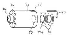
図15は第1変形例のカプセル内視鏡3Hを分解して示す。このカプセル内視鏡3Hは図14における後カバー63内の電池19部分を分離して、カプセル本体61の後端に着脱できるようにしたものである。
【0075】
つまり、この変形例ではカプセル本体61の後端側にネジ部71を設け、このネジ部71に螺合する電池ボックス72を着脱自在で装着できるようにしている。
【0076】
この電池ボックス72内には、ここでは図示していない電池19が収納されている。また、この場合にはカプセル本体61の後端面と電池ボックス72の前端面にはリング状の電極を設けている(図15では電池ボックス72側のリング状電極73a、73bのみを示す)。
【0077】
そして、カプセル本体61に電池ボックス72を装着した後、第1の実施の形態と同様に透明カバー62と(電池19を有しない)後カバー74で気密/水密的に覆うようにする。
【0078】
内視鏡検査に使用した後に回収して洗浄及び滅菌にした後、透明カバー62及び後カバー74を外してカプセル本体側を取り出し、電池ボックス72を新しいものに交換し、新しい透明カバー61及び後カバー74で覆うことにより、次の検査に使用することができる。
【0079】
なお、短い時間の使用の場合で、電池19がまだ使える場合には電池ボックス72を交換しないで使用することもできる。つまり図14の場合よりも、再利用できる部品を増大できる。
【0080】
図16は第2変形例におけるカプセル本体及び電池周辺部分を示す。この変形例では図15に示す電池ボックス72を使用しないで、カプセル本体61の後端面に電池19の凸部の電極19aが嵌合して導通する凹部電極75を設けると共に、電池19の他方の電極と導通させるL字状の接続電極76の前端を嵌合して導通する溝部電極77を設けている。
【0081】
そしてこのカプセル本体61に電池19を接続電極76により電気的に接続した状態で第1変形例と同様に透明カバー61と後カバー74で覆うようにする。
この変形例によれば、使い捨ての電池ボックス72を使用しないでも済む利点がある。また、部品コストを下げることができる。
【0082】
図17は第3変形例を示し、後カバー80の構造を示す。
この後カバー80は図14のカプセル内視鏡3Gの後カバー63において、電池19の他に、pHを検出するpHセンサ81と、このpHセンサ81の検出信号により大腸に到達したことを検知する制御回路82と、制御回路82により大腸に到達した場合に駆動されるモータ83とを設けると共に、モータ83の回転軸は発泡剤収納部67側に突出し、その端部には発泡剤放出口69が設けられた内壁面に当接するように設けたシャッタ84が取り付けられている。
【0083】
このシャッタ84には図17(B)に示すように開口85が設けてあり、停止状態では後カバー80の後端に設けた発泡剤放出口69はシャッタ84の開口85以外の部分で閉塞されているが、モータ83の回転によりシャッタ84を回転させることにより、発泡剤放出口69はシャッタ84の開口85と重なった状態の時に開口して発泡剤67を放出したりして拡張させることができるようにしている。
なお、本変形例の場合には、発泡剤放出口69はアゾポリマ膜70で覆う必要がない。
【0084】
なお、さらに他の変形例として、発泡剤放出口69をアゾポリマ膜70で覆い、発泡剤収納部68に圧力センサを配置し、圧力センサの検出信号により、圧力が低下した場合に、撮像開始するようにしても良い。
【0085】
つまり、発泡剤収納部68に発泡剤67が充填された状態では圧力センサによる検出圧力は大きい値を示し、大腸に到達してアゾポリマ膜70が溶け、発泡剤収納部68内部の発泡剤67が減少すると、検出圧力が小さくなることにより、図14の通信&制御回路64は撮像動作を開始するようにしても良い。
【0086】
なお、上述した各実施の形態ではカプセル内視鏡3等から、マイクロ波等のRF信号で外部の体外ユニット4等に撮像した画像データを送信するようにしているが、この他に例えば磁気信号で体外に送信するようにしても良い。
【0087】
[付記]
1. 撮像手段と照明手段とを有するカプセル内視鏡において、
発泡剤収納部と、
上記発泡剤収納部に収納された発泡剤と、
上記発泡剤収納部に設けられた発泡剤放出口と、
上記発泡剤放出口から発泡剤を放出させる発泡剤放出手段と、
を具備したことを特徴とするカプセル内視鏡。
【0088】
1.2 付記1において、発泡剤放出手段が、上記発泡剤を封入したマイクロカプセルと、
体外超音波発生装置とからなり、
上記マイクロカプセルは超音波によって破壊する。
1.3 付記1において、発泡剤放出手段が、発泡剤放出口に設けたアゾポリマ膜である。
1.4 付記1において、発泡剤放出手段が、開閉可能な発泡剤放出口と、
上記発泡剤放出口を解放させる開閉手段と、
上記開閉手段の開閉をコントロールするタイマ手段と、
からなる。
【0089】
1.5 付記1において、上記発泡剤放出手段が開閉可能な発泡剤放出口と、
上記発泡剤放出口を解放させる開閉手段と、
上記開閉手段の開閉を外部信号によってコントロールする制御手段と、
からなる。
1.5.1 付記1.5において、上記外部信号がRF信号である。
1.5.2 付記1.5において、上記外部信号が磁気信号である。
1.6 付記1において、上記発泡剤放出手段が開閉可能な発泡剤放出口と、
上記発泡剤放出口を解放させる開閉手段と、
所望の状態を検知するセンサと、
上記開閉手段の開閉を上記センサの検出信号によってコントロールする制御手段と、
からなる。
1.7 付記1において、発泡剤が炭酸塩と有機酸からなる。
【0090】
2.撮像手段と照明手段とからなるカプセル内視鏡において、
円筒形状の外装と、
上記外装に螺旋溝を形成し、
上記撮像手段及び照明手段を外装の円筒軸方向斜め方向に設けたことを特徴とするカプセル内視鏡。
2.1 付記2において、上記カプセル内視鏡にチューブ状の挿入部が連接されている。
(問題点) 今まで視野が限られていて見られる範囲が狭かった。
(効果) 視野を斜めにし、蠕動によって受動的に回転させることによって、見落としを少なくできる。
【0091】
3.撮像手段と照明手段とからなるカプセル内視鏡において、
円筒形状の外装と、
上記外装に螺旋状の突起を形成し、
上記撮像手段及び照明手段を外装の円筒軸方向に対して斜め方向に設けた
ことを特徴とするカプセル内視鏡。
【0092】
3.1 付記3において、上記カプセル内視鏡にチューブ状の挿入部が連接されている。
(問題点) 今まで視野が限られていて見られる範囲が狭かった。
(効果) 視野を斜めにし、蠕動によって受動的に回転させることによって、見落としを少なくできる。
【0093】
4.撮像手段と照明手段とからなるカプセル内視鏡において、
大腸到達を検知する大腸到達検知手段と、
別体で体外にある警告装置と、
上記大腸到達検知手段の検知結果を上記警告装置に送信する送信手段とからなることを特徴とするカプセル内視鏡。
4.1 付記4において、大腸到達検知手段はpHセンサである。
4.2 付記4において、大腸到達検知手段は重力方向検知手段である。
4.3 付記4において、大腸到達検知手段は速度センサあるいは加速度センサである。
4.4 付記4において、大腸到達検知手段は大腸内の物質(細菌、酵素など)に選択的に反応するセンサである。
4.5 付記4において、上記警告装置には通知用のランプあるいはブザーあるいは振動子が設けられている。
(問題点) 大腸のみを観察したい場合でも、大腸に到達したことがわからなかったため、大腸到達以前から電源を付けていなくてはならないなど、不便が多かった。
(効果) 大腸到達手段によって大腸到達がわかるため、そこから主電源をONにして省エネしたり、被検者に横になってもらいカプセルの進行を早めるなどの処理ができ、便利になる。
【0094】
5. 撮像手段と照明手段とを設けたカプセル本体部と、
上記カプセル本体部とは別体になった電源装置と、
上記本体部と電源装置を水密に覆う外装部材と
からなることを特徴とするカプセル内視鏡。
5.1 付記5において、上記外装部材と電源装置が一体になった。
(問題点) 従来はカプセルと内部の機能部分が一体になっており、再利用する場合にカプセルを丸ごと消毒・殺菌する必要があり、不便だった。
(効果) 外装と中身を別体にしたため、再利用時には外装を取り換えるだけで済むので、簡便で衛生的。
【0095】
6. 撮像手段と照明手段とを設けたカプセル本体部と、
上記本体部と電源装置を水密に覆う外装部材とからなり、
再利用の際に、上記外装を未使用品に交換して使用することを特徴とするカプセル内視鏡。
(問題点) 従来はカプセルと内部の機能部分が一体になっており、再利用する場合にカプセルを丸ごと消毒・殺菌する必要があり、不便だった。
(効果) 外装と中身を別体にしたため、再利用時には外装を取り換えるだけで済むので、簡便で衛生的。
【0096】
7.撮像手段と照明手段とからなるカプセル内視鏡において、
カプセル外表面に設けた少なくとも二つのバイポーラ電極と、
上記バイポーラ電極に接続され、電気エネルギーを供給するコンデンサと、
上記コンデンサへの蓄電をコントロールする制御回路と、
上記コンデンサおよび制御回路にエネルギーを送る電池とからなることを特徴とするカプセル内視鏡。
7.1 付記7において、上記バイポーラ電極が螺旋状の突起を形成している。
7.2 付記7において、上記バイポーラ電極が輪状である。
(問題点) 治療可能なカプセル内視鏡のアイディアは以前からあるが、サイズや駆動力の制約からいまだにそのようなカプセル内視鏡は実現されていない。
(効果) 止血治療が可能になる。
【0097】
【発明の効果】
以上説明したように本発明によれば、撮像手段と照明手段とを有するカプセル内視鏡において、
発泡剤収納部と、
上記発泡剤収納部に収納された発泡剤と、
上記発泡剤収納部に設けられた発泡剤放出口と、
上記発泡剤放出口から発泡剤を放出させる発泡剤放出手段と、
を具備しているので、カプセル内視鏡で検査される管腔部分において、発泡剤収納部に収納された発泡剤を発泡剤放出口から放出させることで、管腔部分を拡張状態に設定でき、視野を確保して所望とする観察像を得られる。
【図面の簡単な説明】
【図1】本発明の第1の実施の形態を備えたカプセル内視鏡システムの全体図。
【図2】第1の実施の形態のカプセル内視鏡の外観図。
【図3】カプセル内視鏡の内部構成を示す図。
【図4】カプセル内視鏡、体外ユニット、表示システムの電気系の構成を示すブロック図。
【図5】本実施の形態の作用の説明図。
【図6】変形例のカプセル内視鏡の内部構成を示す図。
【図7】図6のカプセル内視鏡の作用の説明図。
【図8】本発明の第2の実施の形態のカプセル内視鏡の外観等を示す図。
【図9】本実施の形態の作用の説明図。
【図10】本実施の形態の他の作用の説明図。
【図11】変形例のカプセル内視鏡を示す図。
【図12】他の変形例のカプセル内視鏡を示す図。
【図13】さらに他の変形例のカプセル内視鏡を示す図。
【図14】本発明の第3の実施の形態のカプセル内視鏡の内部構造等を示す図。
【図15】変形例のカプセル内視鏡を分解して示す図。
【図16】他の変形例のカプセル内視鏡の一部を分解して示す図。
【図17】更に他の変形例における後カバーを示す図。
【符号の説明】
1…カプセル内視鏡システム
2…被検者
3…カプセル内視鏡
4…体外ユニット
5…体外ユニット装着部
6…表示装置
7…表示システム
11…カプセル枠体
12…透明部材
13…メッシュ部材
14…マイクロカプセル
15…LED
16…対物レンズ
17…CMOSイメージャ
18…回路部
19…電池
21、31…アンテナ
22…pHセンサ
24…LED駆動回路
25…制御/処理回路
26…CMOS駆動回路
27、40…画像処理回路
28、33…送受信回路
34、39…メモリ
35、43…制御回路
36、37…コネクタ
44…キーボード[0001]
BACKGROUND OF THE INVENTION
The present invention relates to a capsule endoscope having means for expanding a lumen to secure an observation visual field.And capsule endoscope systemAbout.
[0002]
[Prior art]
In recent years, endoscopes for observing and diagnosing a body cavity or the like by inserting an elongated insertion portion have been widely used.
[0003]
On the other hand, for example, Japanese Patent Application Laid-Open No. 2001-95755 discloses a capsule endoscope that can observe a deep part in a body cavity by encapsulating the patient so that the pain given to the patient can be reduced. .
[0004]
This conventional capsule endoscope is structured to illuminate with an illuminator, connect an object image to an image sensor with an objective lens, and transmit an image signal from the image sensor wirelessly.
[0005]
[Problems to be solved by the invention]
In such a conventional example, for example, when observing a lumen such as the inside of the large intestine, if the lumen is in an expanded state, an observation image of the inner wall of the lumen can be obtained, but the lumen is not expanded. In this case, it is expected that a desired observation image cannot be obtained because a sufficient field of view cannot be secured.
[0006]
(Object of invention)
The present invention has been made in view of the above-described points, and is a capsule endoscope suitable for obtaining a desired observation image by expanding a lumen portion to be inspected by a capsule endoscope.And capsule endoscope systemThe purpose is to provide.
[0007]
[Means for Solving the Problems]
The capsule endoscope of the present invention isA capsule body; an imaging means provided in the capsule body; an illumination means provided in the capsule body; a sheath provided in the capsule body and having a cylindrical shape and substantially hemispherical at both ends; and the sheath A spiral portion that advances while rotating the capsule body;Large intestine arrival detection means for detecting arrival at the large intestine, and transmission means for separately transmitting the detection result of the large intestine arrival detection means and the imaging signal from the imaging means to an extracorporeal unit outside the subject. Features.
The capsule endoscope system of the present invention starts imaging on the capsule endoscope side in response to the reception of the detection result of the large intestine arrival detection means from the capsule endoscope and the capsule endoscope. An extracorporeal unit that transmits a control signal, and when the large intestine arrival detection means detects that the capsule endoscope has reached the site to be examined, the detection result is transmitted to the extracorporeal unit. The imaging by the imaging means is started at a time or after a predetermined time.
[0008]
DETAILED DESCRIPTION OF THE INVENTION
Embodiments of the present invention will be described below with reference to the drawings.
(First embodiment)
1 to 5 relate to a first embodiment of the present invention, FIG. 1 shows an entire capsule endoscope system including the first embodiment, and FIG. 2 shows the first embodiment. FIG. 3 shows the internal configuration of the capsule endoscope, FIG. 4 shows the configuration of the capsule endoscope, the external unit, and the electrical system of the display system, and FIG. 5 shows the configuration of the present embodiment. Shows the effect.
[0009]
As shown in FIG. 1, a capsule endoscope system 1 includes a
[0010]
As shown in FIGS. 2 and 3, the
More specifically, as shown in FIG. 3, the
[0011]
The
[0012]
An
Further, for example, a
[0013]
In addition, inside the
[0014]
In addition, a
[0015]
Based on the pH detected by the
[0016]
FIG. 4A shows a more detailed electric system configuration of the
[0017]
The
The subject in the body illuminated by the
[0018]
In the
[0019]
The image signal is converted into a compressed image signal by the
[0020]
When the control /
On the other hand, the extracorporeal unit 4 that receives image data and the like from the
[0021]
The extracorporeal unit 4 blinks the
[0022]
The electric system configuration of the extracorporeal unit 4 is shown in FIG.
The signal received by the
[0023]
When a signal indicating that the pH is a predetermined pH is detected by the demodulating process by the transmission /
[0024]
As will be described later, when the
[0025]
This foaming agent reacts with the water in the large intestine to evaporate the foaming agent and expand the large intestine. In addition, the
[0026]
The
[0027]
For example, the 1/30
[0028]
Further, the
Further, the
[0029]
This
[0030]
The personal computer
[0031]
The
[0032]
For example, the operation of the capsule endoscope system 1 having such a configuration when performing endoscopy of the large intestine will be described.
As shown in FIG. 1, the
[0033]
Then, the
[0034]
More specifically, when the
[0035]
Then, the
[0036]
As described above, in this embodiment, the
[0037]
When the control /
[0038]
When the extracorporeal unit 4 receives this signal, the
[0039]
By this ultrasonic irradiation, the
The foaming agent reacts with the water in the
[0040]
When it is detected that the
[0041]
In this case, since the inside of the
[0042]
The extracorporeal unit 4 receives the image data sent intermittently and stores it in the
The surgeon diagnoses the
[0043]
According to the present embodiment, when the test site is imaged with the
[0044]
In addition, since imaging is performed at a site where inspection is desired, electric energy can be used effectively. Further, the surgeon can make a diagnosis in a short time by displaying image data taken intermittently.
[0045]
As a first modification, instead of using the
[0046]
As a second modification, for example, a speed sensor may be employed as means for detecting the direction of gravity instead of the
The
[0047]
This
[0048]
After the detection, as described with reference to FIG. 5C, the external
[0049]
An acceleration sensor may be employed instead of the
The effect of this modification is the same as that of the first embodiment.
[0050]
(Second Embodiment)
Next, a second embodiment of the present invention will be described with reference to FIGS.
FIG. 8 shows a
[0051]
8 is a
[0052]
In other words, on the front end side of the
In addition, a configuration is provided in which a
[0053]
Further, in the
[0054]
As shown in FIG. 8C, the
[0055]
That is, each
Therefore, when the
[0056]
FIG. 9 is an explanatory diagram of the operation of the present embodiment.
As shown in FIG. 9A, when the
[0057]
When the
[0058]
Thereafter, as shown in FIG. 9D (by irradiating ultrasonic waves from outside the body), the
[0059]
FIG. 10 shows the progress of the
[0060]
Therefore, the present embodiment has the same effect as the first embodiment, and further, can be imaged by rotating in a spiral shape, so that it is easy to capture the entire lumen without fail. . In addition, since it is a perspective imaging means, an image can be obtained that makes it easier to diagnose the luminal part than in direct viewing.
As a first modification of the present embodiment, the foaming agent is filled and stored inside the
[0061]
With the configuration of this modification, the foaming agent is automatically vaporized when the
Therefore, according to this modification, since the large intestine can be automatically expanded, there is an effect that necessary operations can be further simplified.
[0062]
FIG. 11 shows a second modification. This capsule endoscope 3D is connected to the
[0063]
FIG. 12 shows a
In the
[0064]
That is, the
[0065]
In FIG. 12, the functions of the
[0066]
(Third embodiment)
Next, a third embodiment of the present invention will be described with reference to FIG. FIG. 14A shows a longitudinal section of the capsule endoscope of the third embodiment, and FIG. 14B shows an exploded state. In this embodiment, the capsule endoscope has a double structure, and the inside thereof can be reused.
[0067]
Therefore, the
[0068]
The
[0069]
A
The communication &
[0070]
[0071]
In addition, the
In addition, a foaming
[0072]
A foaming
In the
[0073]
Accordingly, when the
Then, the
[0074]
According to the present embodiment, since the
FIG. 15 is an exploded view of the
[0075]
That is, in this modification, a
[0076]
A battery 19 (not shown) is housed in the
[0077]
Then, after the
[0078]
After being used for endoscopy, recovered, cleaned and sterilized, the
[0079]
If the
[0080]
FIG. 16 shows a capsule body and a battery peripheral portion in the second modification. In this modified example, the
[0081]
The
According to this modification, there is an advantage that it is not necessary to use the
[0082]
FIG. 17 shows a third modification and shows the structure of the
This
[0083]
The
In the case of this modification, it is not necessary to cover the foaming
[0084]
As still another modification, the foaming
[0085]
That is, when the
[0086]
In each of the above-described embodiments, image data picked up by the
[0087]
[Appendix]
1. In a capsule endoscope having an imaging means and an illumination means,
A foaming agent storage section;
A foaming agent stored in the foaming agent storage unit;
A foaming agent outlet provided in the foaming agent storage unit;
A blowing agent releasing means for releasing the blowing agent from the blowing agent discharge port;
A capsule endoscope characterized by comprising:
[0088]
1.2 In Supplementary Note 1, the foaming agent releasing means includes a microcapsule enclosing the foaming agent;
Consisting of an extracorporeal ultrasound generator,
The microcapsules are broken by ultrasonic waves.
1.3 In Supplementary Note 1, the foaming agent releasing means is an azo polymer film provided at the foaming agent discharge port.
1.4 In Supplementary Note 1, the foaming agent discharge means includes a foaming agent discharge port that can be opened and closed;
Opening and closing means for releasing the blowing agent discharge port;
Timer means for controlling opening and closing of the opening and closing means;
Consists of.
[0089]
1.5 In Supplementary Note 1, the foaming agent discharge port capable of opening and closing the foaming agent releasing means;
Opening and closing means for releasing the blowing agent discharge port;
Control means for controlling the opening and closing of the opening and closing means by an external signal;
Consists of.
1.5.1 In Appendix 1.5, the external signal is an RF signal.
1.5.2 In Appendix 1.5, the external signal is a magnetic signal.
1.6 In Supplementary Note 1, the foaming agent discharge port capable of opening and closing the foaming agent releasing means;
Opening and closing means for releasing the blowing agent discharge port;
A sensor for detecting a desired state;
Control means for controlling the opening and closing of the opening and closing means by a detection signal of the sensor;
Consists of.
1.7 In Supplementary Note 1, the foaming agent comprises a carbonate and an organic acid.
[0090]
2. In a capsule endoscope comprising an imaging means and an illumination means,
A cylindrical exterior;
Forming a spiral groove in the exterior,
A capsule endoscope characterized in that the imaging means and the illuminating means are provided obliquely in the direction of the cylindrical axis of the exterior.
2.1 In
(Problem) Until now, the field of view has been limited and the range that can be seen has been narrow.
(Effects) Overlooking can be reduced by tilting the field of view and passively rotating the field of view.
[0091]
3. In a capsule endoscope comprising an imaging means and an illumination means,
A cylindrical exterior;
Forming a spiral protrusion on the exterior,
The imaging means and the illumination means are arranged in the direction of the cylindrical axis of the exterior.AgainstProvided in an oblique direction
A capsule endoscope characterized by that.
[0092]
3.1 In
(Problem) Until now, the field of view has been limited and the range that can be seen has been narrow.
(Effects) Overlooking can be reduced by tilting the field of view and passively rotating the field of view.
[0093]
4). In a capsule endoscope comprising an imaging means and an illumination means,
Large intestine arrival detection means for detecting large intestine arrival;
A separate and external warning device,
A capsule endoscope comprising: transmission means for transmitting the detection result of the large intestine arrival detection means to the warning device.
4.1 In Appendix 4, the colon arrival detection means is a pH sensor.
4.2 In Supplementary Note 4, large intestine arrival detection means is gravity direction detection means.
4.3 In Appendix 4, the colon arrival detection means is a speed sensor or an acceleration sensor.
4.4 In Appendix 4, the colon arrival detection means is a sensor that selectively reacts with substances (bacteria, enzymes, etc.) in the large intestine.
4.5 In Supplementary Note 4, the warning device is provided with a notification lamp, buzzer or vibrator.
(Problem) Even when only the large intestine was desired to be observed, it was inconvenient that the power had to be turned on before reaching the large intestine because it was not known that it had reached the large intestine.
(Effect) Since the arrival at the large intestine is known by the means for reaching the large intestine, the main power is turned on to save energy, and the subject can be laid down to speed up the progress of the capsule, which is convenient.
[0094]
5. A capsule body provided with imaging means and illumination means;
A power supply unit separated from the capsule body,
An exterior member for watertightly covering the main body and the power supply device;
A capsule endoscope characterized by comprising:
5.1 In
(Problem) Conventionally, the capsule and the internal functional part are integrated, and it is necessary to disinfect and sterilize the entire capsule when reused, which is inconvenient.
(Effect) Since the exterior and contents are separated, it is only necessary to replace the exterior when reused, so it is simple and hygienic.
[0095]
6). A capsule body provided with imaging means and illumination means;
It consists of an exterior member that covers the main body and the power supply device in a watertight manner,
A capsule endoscope, wherein the exterior is replaced with an unused one when reused.
(Problem) Conventionally, the capsule and the internal functional part are integrated, and it is necessary to disinfect and sterilize the entire capsule when reused, which is inconvenient.
(Effect) Since the exterior and contents are separated, it is only necessary to replace the exterior when reused, so it is simple and hygienic.
[0096]
7). In a capsule endoscope comprising an imaging means and an illumination means,
At least two bipolar electrodes provided on the outer surface of the capsule;
A capacitor connected to the bipolar electrode for supplying electrical energy;
A control circuit for controlling power storage in the capacitor;
A capsule endoscope comprising the capacitor and a battery for sending energy to the control circuit.
7.1 In Additional Description 7, the bipolar electrode forms a spiral protrusion.
7.2 In Supplementary Note 7, the bipolar electrode is ring-shaped.
(Problem) Although there has been an idea of a capsule endoscope that can be treated for a long time, such a capsule endoscope has not yet been realized due to restrictions on size and driving force.
(Effect) Hemostasis treatment is possible.
[0097]
【The invention's effect】
As described above, according to the present invention, in the capsule endoscope having the imaging means and the illumination means,
A foaming agent storage section;
A foaming agent stored in the foaming agent storage unit;
A foaming agent outlet provided in the foaming agent storage unit;
A blowing agent releasing means for releasing the blowing agent from the blowing agent discharge port;
Therefore, in the lumen part to be inspected by the capsule endoscope, the lumen part can be set in the expanded state by releasing the foaming agent stored in the foaming agent storage part from the foaming agent discharge port. A desired observation image can be obtained by securing a visual field.
[Brief description of the drawings]
FIG. 1 is an overall view of a capsule endoscope system including a first embodiment of the present invention.
FIG. 2 is an external view of a capsule endoscope according to the first embodiment.
FIG. 3 is a diagram showing an internal configuration of a capsule endoscope.
FIG. 4 is a block diagram showing a configuration of an electrical system of a capsule endoscope, an extracorporeal unit, and a display system.
FIG. 5 is an explanatory diagram of the operation of the present embodiment.
FIG. 6 is a diagram showing an internal configuration of a capsule endoscope according to a modified example.
7 is an explanatory diagram of the operation of the capsule endoscope of FIG. 6. FIG.
FIG. 8 is a diagram showing an appearance and the like of a capsule endoscope according to a second embodiment of the present invention.
FIG. 9 is an explanatory diagram of the operation of the present embodiment.
FIG. 10 is an explanatory diagram of another operation of the present embodiment.
FIG. 11 is a view showing a capsule endoscope of a modified example.
FIG. 12 is a diagram showing a capsule endoscope according to another modification.
FIG. 13 is a view showing a capsule endoscope of still another modified example.
FIG. 14 is a diagram showing an internal structure and the like of a capsule endoscope according to a third embodiment of the present invention.
FIG. 15 is an exploded view of a capsule endoscope according to a modified example.
FIG. 16 is an exploded view showing a part of a capsule endoscope according to another modification.
FIG. 17 is a view showing a rear cover in still another modified example.
[Explanation of symbols]
1 ... Capsule endoscope system
2 ... Subject
3. Capsule endoscope
4 ... Extracorporeal unit
5 ... External unit mounting part
6 ... Display device
7 ... Display system
11 ... capsule frame
12 ... Transparent member
13 ... Mesh member
14 ... Microcapsules
15 ... LED
16 ... Objective lens
17 ... CMOS imager
18 ... Circuit section
19 ... Battery
21, 31 ... Antenna
22 ... pH sensor
24 ... LED drive circuit
25. Control / processing circuit
26 ... CMOS drive circuit
27, 40 ... Image processing circuit
28, 33 ... transmission / reception circuit
34, 39 ... Memory
35, 43 ... control circuit
36, 37 ... Connector
44 ... Keyboard
Claims (12)
Translated fromJapanese前記カプセル本体に設けられた撮像手段と、
前記カプセル本体に設けられた照明手段と、
前記カプセル本体に設けられ、円筒形状で、その両端が略半球形状である外装と、
前記外装に設けられ、前記カプセル本体を回転しながら前進させる螺旋部と、
大腸到達を検知する大腸到達検知手段と、
前記大腸到達検知手段の検知結果および前記撮像手段での撮像信号を別体で被検体外にある体外ユニットに送信する送信手段と、
を具備したことを特徴とするカプセル内視鏡。A capsule body;
Imaging means provided in the capsule body;
Illumination means provided in the capsule body;
Provided in the capsule body, in a cylindrical shape, and an exterior that is substantially hemispherical at both ends;
A spiral portion provided in the exterior and moving forward while rotating the capsule body;
Large intestine arrival detection means for detecting large intestine arrival;
Transmitting means for transmitting the detection result of the large intestine arrival detection means and the imaging signal in the imaging means separately to an extracorporeal unit outside the subject;
A capsule endoscopecharacterized by comprising:
前記カプセル内視鏡からの前記大腸到達検知手段の検出結果の受信に対応して、前記カプセル内視鏡側に撮像を開始させる制御信号を送信する体外ユニットと、 In response to reception of the detection result of the large intestine arrival detection means from the capsule endoscope, an extracorporeal unit that transmits a control signal for starting imaging on the capsule endoscope side,
を具備し、 Comprising
前記大腸到達検知手段によって前記カプセル内視鏡が検査を行う部位に到達したことが検出されると、当該検出結果が前記体外ユニットに送信された時点または所定時間の後に前記撮像手段での撮像が開始される When it is detected by the large intestine arrival detection means that the capsule endoscope has reached the site to be inspected, the imaging means picks up an image when the detection result is transmitted to the extracorporeal unit or after a predetermined time. Be started
ことを特徴とするカプセル内視鏡システム。 A capsule endoscope system characterized by that.
前記発泡剤収納部に設けられた発泡剤放出口と、 A foaming agent outlet provided in the foaming agent storage unit;
前記発泡剤放出口から発泡剤を放出させる発泡剤放出手段と、 A blowing agent releasing means for releasing the blowing agent from the blowing agent discharge port;
を具備したことを特徴とする請求項2−4のいずれか一項に記載のカプセル内視鏡システム。 The capsule endoscope system according to any one of claims 2 to 4, wherein the capsule endoscope system is provided.
前記発泡剤放出口を開放させる開閉手段と、 Opening and closing means for opening the foaming agent outlet;
前記開閉手段の開閉をコントロールする制御手段と、 Control means for controlling opening and closing of the opening and closing means;
を具備したことを特徴とする請求項6に記載のカプセル内視鏡システム。 The capsule endoscope system according to claim 6, comprising:
前記制御手段は、前記センサの検出信号によって前記開閉手段の開閉をコントロールすることを特徴とする請求項10に記載のカプセル内視鏡システム。 The capsule endoscope system according to claim 10, wherein the control unit controls opening / closing of the opening / closing unit based on a detection signal of the sensor.
当該外装側面と前側部分とを覆う透明カバーと、 A transparent cover covering the exterior side surface and the front side portion;
後側部分を覆う後カバーと、 A rear cover covering the rear side part,
を備え、 With
前記後カバーは、前記発泡剤収納部を有し、 The rear cover has the foaming agent storage part,
前記透明カバーと前記後カバーとの中に前記カプセル本体が配設され、当該カプセル内視鏡での検査が行われた後には、前記透明カバーと後カバーとから前記カプセル本体を取り出して新しい透明カバーと後カバーの中に配設して次の内視鏡検査に使用可能としたことを特徴とする請求項6−11のいずれか一項に記載のカプセル内視鏡システム。 The capsule body is disposed in the transparent cover and the rear cover, and after the inspection with the capsule endoscope, the capsule body is taken out from the transparent cover and the rear cover to obtain a new transparent body. The capsule endoscope system according to any one of claims 6 to 11, wherein the capsule endoscope system is arranged in a cover and a rear cover and can be used for the next endoscopy.
Priority Applications (2)
| Application Number | Priority Date | Filing Date | Title |
|---|---|---|---|
| JP2001229951AJP4744026B2 (en) | 2001-07-30 | 2001-07-30 | Capsule endoscope and capsule endoscope system |
| US10/205,530US7511733B2 (en) | 2001-07-30 | 2002-07-25 | Capsule-type medical apparatus |
Applications Claiming Priority (1)
| Application Number | Priority Date | Filing Date | Title |
|---|---|---|---|
| JP2001229951AJP4744026B2 (en) | 2001-07-30 | 2001-07-30 | Capsule endoscope and capsule endoscope system |
Publications (3)
| Publication Number | Publication Date |
|---|---|
| JP2003038424A JP2003038424A (en) | 2003-02-12 |
| JP2003038424A5 JP2003038424A5 (en) | 2008-07-31 |
| JP4744026B2true JP4744026B2 (en) | 2011-08-10 |
Family
ID=19062236
Family Applications (1)
| Application Number | Title | Priority Date | Filing Date |
|---|---|---|---|
| JP2001229951AExpired - Fee RelatedJP4744026B2 (en) | 2001-07-30 | 2001-07-30 | Capsule endoscope and capsule endoscope system |
Country Status (2)
| Country | Link |
|---|---|
| US (1) | US7511733B2 (en) |
| JP (1) | JP4744026B2 (en) |
Cited By (1)
| Publication number | Priority date | Publication date | Assignee | Title |
|---|---|---|---|---|
| WO2019093787A3 (en)* | 2017-11-08 | 2019-07-18 | 서울바이오시스주식회사 | Medical capsule device |
Families Citing this family (333)
| Publication number | Priority date | Publication date | Assignee | Title |
|---|---|---|---|---|
| IL126727A (en) | 1998-10-22 | 2006-12-31 | Given Imaging Ltd | Method for delivering a device to a target location |
| US8636648B2 (en) | 1999-03-01 | 2014-01-28 | West View Research, Llc | Endoscopic smart probe |
| US6470060B1 (en)* | 1999-03-01 | 2002-10-22 | Micron Technology, Inc. | Method and apparatus for generating a phase dependent control signal |
| US10973397B2 (en)* | 1999-03-01 | 2021-04-13 | West View Research, Llc | Computerized information collection and processing apparatus |
| US7996067B2 (en)* | 1999-06-15 | 2011-08-09 | Given Imaging Ltd. | In-vivo imaging device, optical system and method |
| IL130486A (en)* | 1999-06-15 | 2005-08-31 | Given Imaging Ltd | Optical system |
| US7813789B2 (en)* | 1999-06-15 | 2010-10-12 | Given Imaging Ltd. | In-vivo imaging device, optical system and method |
| AU2001227020A1 (en)* | 2000-01-19 | 2001-07-31 | Given Imaging Ltd. | A system for detecting substances |
| EP1982636B2 (en)* | 2001-06-18 | 2016-09-07 | Given Imaging Ltd. | In vivo sensing device with a circuit board having rigid sections and flexible sections |
| JP4663230B2 (en)* | 2001-06-28 | 2011-04-06 | ギブン イメージング リミテッド | In vivo imaging device having a small cross-sectional area and method for constructing the same |
| US20060184039A1 (en) | 2001-07-26 | 2006-08-17 | Dov Avni | Apparatus and method for light control in an in-vivo imaging device |
| IL155046A (en)* | 2003-03-23 | 2013-12-31 | Given Imaging Ltd | In-vivo imaging device capable of defining its location |
| US9113846B2 (en) | 2001-07-26 | 2015-08-25 | Given Imaging Ltd. | In-vivo imaging device providing data compression |
| US9149175B2 (en) | 2001-07-26 | 2015-10-06 | Given Imaging Ltd. | Apparatus and method for light control in an in-vivo imaging device |
| US20050187433A1 (en)* | 2001-07-26 | 2005-08-25 | Given Imaging Ltd. | In-vivo imaging device providing constant bit rate transmission |
| US7474327B2 (en) | 2002-02-12 | 2009-01-06 | Given Imaging Ltd. | System and method for displaying an image stream |
| US8022980B2 (en) | 2002-02-12 | 2011-09-20 | Given Imaging Ltd. | System and method for displaying an image stream |
| JP4363843B2 (en) | 2002-03-08 | 2009-11-11 | オリンパス株式会社 | Capsule endoscope |
| US20030216622A1 (en)* | 2002-04-25 | 2003-11-20 | Gavriel Meron | Device and method for orienting a device in vivo |
| US7662094B2 (en)* | 2002-05-14 | 2010-02-16 | Given Imaging Ltd. | Optical head assembly with dome, and device for use thereof |
| EP1536731A2 (en)* | 2002-08-01 | 2005-06-08 | The Johns Hopkins University | Techniques for identifying molecular structures and treating cell types lining a body lumen using fluorescence |
| US7473218B2 (en) | 2002-08-06 | 2009-01-06 | Olympus Corporation | Assembling method of capsule medical apparatus |
| EP1534120B1 (en)* | 2002-08-13 | 2010-06-09 | Given Imaging Ltd. | System for in vivo sampling and analysis |
| JP4328077B2 (en)* | 2002-09-27 | 2009-09-09 | オリンパス株式会社 | Ultrasonic diagnostic equipment |
| WO2004028335A2 (en)* | 2002-09-30 | 2004-04-08 | Given Imaging Ltd. | In-vivo sensing system |
| AU2003264858A1 (en)* | 2002-09-30 | 2004-04-19 | Given Imaging Ltd. | Reduced size imaging device |
| AU2003274635A1 (en)* | 2002-10-15 | 2004-05-04 | Given Imaging Ltd. | Device, system and method for transfer of signals to a moving device |
| US20080045788A1 (en)* | 2002-11-27 | 2008-02-21 | Zvika Gilad | Method and device of imaging with an in vivo imager |
| US20040106849A1 (en)* | 2002-12-03 | 2004-06-03 | Cho Jin-Ho | Multi-functional, bi-directional communication telemetry capsule |
| WO2004054430A2 (en) | 2002-12-16 | 2004-07-01 | Given Imaging Ltd. | Device, system and method for selective activation of in vivo sensors |
| US7946979B2 (en)* | 2002-12-26 | 2011-05-24 | Given Imaging, Ltd. | Immobilizable in vivo sensing device |
| WO2004059568A1 (en)* | 2002-12-26 | 2004-07-15 | Given Imaging Ltd. | In vivo imaging device and method of manufacture thereof |
| US20080097149A1 (en)* | 2002-12-30 | 2008-04-24 | Sam Adler | Method for in Vivo Sensing |
| US7628753B2 (en)* | 2002-12-30 | 2009-12-08 | Given Imaging, Ltd. | Method for in vivo sensing |
| JP4503930B2 (en)* | 2003-01-30 | 2010-07-14 | オリンパス株式会社 | Medical equipment |
| US20040152988A1 (en)* | 2003-01-31 | 2004-08-05 | Weirich John Paul | Capsule imaging system |
| JP4091004B2 (en)* | 2003-02-04 | 2008-05-28 | オリンパス株式会社 | Medical device guidance system |
| JP4231707B2 (en)* | 2003-02-25 | 2009-03-04 | オリンパス株式会社 | Capsule medical device |
| JP4149838B2 (en)* | 2003-03-04 | 2008-09-17 | オリンパス株式会社 | Capsule medical device |
| JP4012097B2 (en)* | 2003-03-06 | 2007-11-21 | オリンパス株式会社 | Capsule type medical device collection device |
| IL155175A (en)* | 2003-03-31 | 2012-01-31 | Given Imaging Ltd | Diagnostic device using data compression |
| US20040199054A1 (en)* | 2003-04-03 | 2004-10-07 | Wakefield Glenn Mark | Magnetically propelled capsule endoscopy |
| US20070043263A1 (en)* | 2003-04-03 | 2007-02-22 | Wakefield Glenn M | Simultaneous magnetic control of multiple objects |
| US7316930B1 (en) | 2003-04-21 | 2008-01-08 | National Semiconductor Corporation | Use of vertically stacked photodiodes in a gene chip system |
| US7141016B2 (en)* | 2003-04-25 | 2006-11-28 | Medtronic, Inc. | Systems and methods for monitoring gastrointestinal system |
| JP4370121B2 (en)* | 2003-06-02 | 2009-11-25 | オリンパス株式会社 | Endoscope device |
| EP1643906A2 (en)* | 2003-06-12 | 2006-04-12 | University of Utah Research Foundation | Apparatus, systems and methods for diagnosing carpal tunnel syndrome |
| EP2263513B1 (en)* | 2003-06-24 | 2013-08-07 | Olympus Corporation | Capsule type medical device communication system, capsule type medical device, and biological information reception device |
| JP4451217B2 (en)* | 2004-06-01 | 2010-04-14 | オリンパス株式会社 | Capsule type communication system, capsule type medical device and biological information receiving device |
| IL162740A (en)* | 2003-06-26 | 2010-06-16 | Given Imaging Ltd | Device, method and system for reduced transmission imaging |
| JP4526245B2 (en)* | 2003-07-04 | 2010-08-18 | オリンパス株式会社 | Video signal processing device |
| US20080058989A1 (en)* | 2006-04-13 | 2008-03-06 | Board Of Regents Of The University Of Nebraska | Surgical camera robot |
| US7042184B2 (en)* | 2003-07-08 | 2006-05-09 | Board Of Regents Of The University Of Nebraska | Microrobot for surgical applications |
| US7960935B2 (en) | 2003-07-08 | 2011-06-14 | The Board Of Regents Of The University Of Nebraska | Robotic devices with agent delivery components and related methods |
| JP4270968B2 (en)* | 2003-07-10 | 2009-06-03 | オリンパス株式会社 | Optical apparatus having an optical system having an optical element with an antireflection surface |
| US7066879B2 (en)* | 2003-07-15 | 2006-06-27 | The Trustees Of Columbia University In The City Of New York | Insertable device and system for minimal access procedure |
| JP4436631B2 (en)* | 2003-08-04 | 2010-03-24 | オリンパス株式会社 | Capsule endoscope |
| JP4137740B2 (en)* | 2003-08-06 | 2008-08-20 | オリンパス株式会社 | Capsule type medical device and capsule type medical device guidance system |
| US7623904B2 (en)* | 2003-08-06 | 2009-11-24 | Olympus Corporation | Medical apparatus, medical apparatus guide system, capsule type medical apparatus, and capsule type medical apparatus guide apparatus |
| JP4153845B2 (en)* | 2003-08-11 | 2008-09-24 | オリンパス株式会社 | Medical device guidance system |
| US7399274B1 (en) | 2003-08-19 | 2008-07-15 | National Semiconductor Corporation | Sensor configuration for a capsule endoscope |
| JP4590171B2 (en)* | 2003-08-29 | 2010-12-01 | オリンパス株式会社 | Capsule type medical device and medical device equipped with the capsule type medical device |
| US7153259B2 (en)* | 2003-09-01 | 2006-12-26 | Olympus Corporation | Capsule type endoscope |
| JP3993546B2 (en)* | 2003-09-08 | 2007-10-17 | オリンパス株式会社 | In-subject introduction apparatus and wireless in-subject information acquisition system |
| KR20140134338A (en)* | 2003-09-11 | 2014-11-21 | 테라노스, 인코포레이티드 | Medical device for analyte monitoring and drug delivery |
| JP4520126B2 (en)* | 2003-09-29 | 2010-08-04 | オリンパス株式会社 | Capsule type medical device system |
| JP4868720B2 (en)* | 2004-05-27 | 2012-02-01 | オリンパス株式会社 | Capsule dosing system |
| US8021356B2 (en) | 2003-09-29 | 2011-09-20 | Olympus Corporation | Capsule medication administration system, medication administration method using capsule medication administration system, control method for capsule medication administration system |
| JP4733918B2 (en) | 2003-10-01 | 2011-07-27 | オリンパス株式会社 | Capsule dosing system |
| US20080234546A1 (en)* | 2003-10-01 | 2008-09-25 | Olympus Corporation | In vivo observation device |
| JP4503979B2 (en)* | 2003-10-22 | 2010-07-14 | オリンパス株式会社 | Internal devices and medical devices |
| US20050124875A1 (en)* | 2003-10-01 | 2005-06-09 | Olympus Corporation | Vivo observation device |
| DE10346678A1 (en)* | 2003-10-08 | 2005-05-12 | Siemens Ag | Endoscopy device comprising an endoscopy capsule or an endoscopy head with an image recording device and imaging method for such an endoscopy device |
| JP4091036B2 (en)* | 2003-11-06 | 2008-05-28 | オリンパス株式会社 | Body cavity moving body |
| US7918786B2 (en) | 2003-11-11 | 2011-04-05 | Olympus Corporation | Capsule type medical device system, and capsule type medical device |
| US7429259B2 (en)* | 2003-12-02 | 2008-09-30 | Cadeddu Jeffrey A | Surgical anchor and system |
| US9392961B2 (en) | 2003-12-17 | 2016-07-19 | Check-Cap Ltd. | Intra-lumen polyp detection |
| JP4759519B2 (en)* | 2003-12-17 | 2011-08-31 | チェック キャップ リミテッド | Detection of intraluminal polyps |
| US20050137468A1 (en)* | 2003-12-18 | 2005-06-23 | Jerome Avron | Device, system, and method for in-vivo sensing of a substance |
| JP2005185567A (en)* | 2003-12-25 | 2005-07-14 | Olympus Corp | Medical capsule apparatus |
| WO2005062715A2 (en) | 2003-12-31 | 2005-07-14 | Given Imaging Ltd. | System and method for displaying an image stream |
| US8702597B2 (en)* | 2003-12-31 | 2014-04-22 | Given Imaging Ltd. | Immobilizable in-vivo imager with moveable focusing mechanism |
| JP2005192821A (en) | 2004-01-07 | 2005-07-21 | Olympus Corp | Capsule type medical apparatus |
| JP2007525261A (en)* | 2004-01-16 | 2007-09-06 | ザ シティ カレッジ オブ ザ シティ ユニバーシティ オブ ニューヨーク | A microscale compact device for in vivo medical diagnostics combining optical imaging and point fluorescence spectroscopy |
| WO2005067783A1 (en)* | 2004-01-19 | 2005-07-28 | Olympus Corporation | Imaging device for endoscope and capsule type endoscope |
| CN1284505C (en)* | 2004-02-28 | 2006-11-15 | 重庆金山科技(集团)有限公司 | Radio capsule like endoscope system for medical use |
| WO2005087083A1 (en)* | 2004-03-18 | 2005-09-22 | Yiqun Lu | A kind of capsule pattern endoscopic |
| EP1727464B1 (en)* | 2004-03-25 | 2008-01-23 | Olympus Corporation | In-vivo information acquisition apparatus and in-vivo information acquisition apparatus system |
| JP4370198B2 (en)* | 2004-05-10 | 2009-11-25 | オリンパス株式会社 | Intra-subject introduction device |
| US7605852B2 (en) | 2004-05-17 | 2009-10-20 | Micron Technology, Inc. | Real-time exposure control for automatic light control |
| JP4584624B2 (en)* | 2004-05-18 | 2010-11-24 | オリンパス株式会社 | Endoscope device |
| WO2005112895A2 (en)* | 2004-05-20 | 2005-12-01 | Spectrum Dynamics Llc | Ingestible device platform for the colon |
| JP4530717B2 (en)* | 2004-05-20 | 2010-08-25 | オリンパス株式会社 | Endoscope |
| US20060015013A1 (en)* | 2004-06-30 | 2006-01-19 | Zvika Gilad | Device and method for in vivo illumination |
| US7596403B2 (en) | 2004-06-30 | 2009-09-29 | Given Imaging Ltd. | System and method for determining path lengths through a body lumen |
| US7643865B2 (en)* | 2004-06-30 | 2010-01-05 | Given Imaging Ltd. | Autonomous in-vivo device |
| JP4445812B2 (en)* | 2004-07-08 | 2010-04-07 | オリンパス株式会社 | Intra-subject introduction apparatus and intra-subject introduction system |
| EP1789128B1 (en) | 2004-08-27 | 2018-05-09 | STOCO 10 GmbH | Electronically and remotely controlled pill and system for delivering at least one medicament |
| JP4578899B2 (en)* | 2004-08-30 | 2010-11-10 | オリンパス株式会社 | Method for manufacturing in-subject introduction device |
| JP2006075331A (en)* | 2004-09-09 | 2006-03-23 | Sanyo Electric Co Ltd | Imaging apparatus for endoscope |
| AU2005229684A1 (en)* | 2004-11-04 | 2006-05-18 | Given Imaging Ltd | Apparatus and method for receiving device selection and combining |
| ATE485074T1 (en)* | 2004-11-29 | 2010-11-15 | Koninkl Philips Electronics Nv | ELECTRONICALLY CONTROLLED TABLET |
| US20060169294A1 (en)* | 2004-12-15 | 2006-08-03 | Kaler Karan V | Inertial navigation method and apparatus for wireless bolus transit monitoring in gastrointestinal tract |
| KR20080028837A (en)* | 2004-12-30 | 2008-04-01 | 기븐 이미징 리미티드 | Swallowable Sensing Device Assembly System and Method |
| WO2006070356A2 (en)* | 2004-12-30 | 2006-07-06 | Given Imaging Ltd. | Device, system, and method for adaptive imaging |
| US8235055B2 (en)* | 2005-01-11 | 2012-08-07 | Uti Limited Partnership | Magnetic levitation of intraluminal microelectronic capsule |
| US7909756B2 (en)* | 2005-01-26 | 2011-03-22 | Karl Storz Imaging, Inc. | Illumination system for variable direction of view instruments |
| US8738106B2 (en)* | 2005-01-31 | 2014-05-27 | Given Imaging, Ltd | Device, system and method for in vivo analysis |
| US8852083B2 (en)* | 2005-02-04 | 2014-10-07 | Uti Limited Partnership | Self-stabilized encapsulated imaging system |
| DE102005007576A1 (en)* | 2005-02-18 | 2006-08-24 | Siemens Ag | Wirelessly navigable by means of a magnetic system capsule for performing a medical procedure in a hollow organ of a patient |
| JP4668643B2 (en)* | 2005-02-23 | 2011-04-13 | オリンパスメディカルシステムズ株式会社 | Endoscope device |
| US20060231110A1 (en)* | 2005-03-24 | 2006-10-19 | Mintchev Martin P | Ingestible capsule for esophageal monitoring |
| CN101141912A (en)* | 2005-03-30 | 2008-03-12 | 奥林巴斯株式会社 | Wireless device for acquiring information on inside of subject and wireless system for acquiring information on inside of subject |
| IL174531A0 (en)* | 2005-04-06 | 2006-08-20 | Given Imaging Ltd | System and method for performing capsule endoscopy diagnosis in remote sites |
| US20060270899A1 (en)* | 2005-05-13 | 2006-11-30 | Omar Amirana | Magnetic pill with camera and electrical properties |
| DE102005024538A1 (en)* | 2005-05-28 | 2006-11-30 | Aziz Bousfiha | Device used to diagnose gastric region comprises micropill remotely controllable and movable by microsystem technique, with live transmission of received pictures by ultrawide band technique |
| DE102005032368B4 (en)* | 2005-07-08 | 2016-01-28 | Siemens Aktiengesellschaft | endoscopy capsule |
| CN101217908B (en)* | 2005-07-08 | 2012-10-24 | 奥林巴斯医疗株式会社 | Apparatus for placing capsule type medical device, apparatus for placing capsule endoscope in the body |
| DE102005032378A1 (en)* | 2005-07-08 | 2007-01-11 | Siemens Ag | Magnetic navigable endoscopy capsule with sensor for detecting a physiological size |
| JP5341513B2 (en)* | 2005-07-20 | 2013-11-13 | ニール・アール.・イウリアーノ | Medication compliance system and related methods |
| JP4734068B2 (en)* | 2005-09-09 | 2011-07-27 | オリンパスメディカルシステムズ株式会社 | Body cavity image observation device |
| US8038608B2 (en)* | 2005-09-09 | 2011-10-18 | Olympus Corporation | Body-cavity image observation apparatus |
| US7983458B2 (en)* | 2005-09-20 | 2011-07-19 | Capso Vision, Inc. | In vivo autonomous camera with on-board data storage or digital wireless transmission in regulatory approved band |
| JP4864003B2 (en)* | 2005-09-30 | 2012-01-25 | オリンパスメディカルシステムズ株式会社 | Rotating self-propelled endoscope device |
| US20090281387A1 (en)* | 2005-10-05 | 2009-11-12 | Olympus Medical Systems Corp. | Capsule-type medical apparatus, guidance system and guidance method therefor, and intrasubject insertion apparatus |
| US7482593B2 (en)* | 2005-10-20 | 2009-01-27 | The Research Foundation Of State University Of New York | Method to determine the depth-of-interaction function for PET detectors |
| JP5030415B2 (en) | 2005-11-16 | 2012-09-19 | オリンパス株式会社 | Endoscope device |
| US20080312532A1 (en)* | 2005-11-18 | 2008-12-18 | Koninklijke Philips Electronics, N.V. | System and Method for Interacting With a Cell or Tissue in a Body |
| US7896805B2 (en) | 2005-11-23 | 2011-03-01 | Given Imaging Ltd. | In-vivo imaging device and optical system thereof |
| JP4789607B2 (en)* | 2005-12-05 | 2011-10-12 | オリンパスメディカルシステムズ株式会社 | Receiver |
| JP4981316B2 (en)* | 2005-12-16 | 2012-07-18 | オリンパスメディカルシステムズ株式会社 | Intra-subject introduction device |
| JP4855771B2 (en)* | 2005-12-20 | 2012-01-18 | オリンパスメディカルシステムズ株式会社 | In-vivo image capturing apparatus and in-vivo image capturing system |
| WO2007074883A1 (en)* | 2005-12-27 | 2007-07-05 | Olympus Medical Systems Corp. | Storage device for medical device, disposal device and method of using medical device |
| EP1969989B1 (en)* | 2005-12-28 | 2016-12-14 | Olympus Corporation | Body-insertable device system and in-vivo observation method |
| US20070156051A1 (en)* | 2005-12-29 | 2007-07-05 | Amit Pascal | Device and method for in-vivo illumination |
| US9320417B2 (en) | 2005-12-29 | 2016-04-26 | Given Imaging Ltd. | In-vivo optical imaging device with backscatter blocking |
| US20070167834A1 (en)* | 2005-12-29 | 2007-07-19 | Amit Pascal | In-vivo imaging optical device and method |
| DE102006014040B4 (en)* | 2006-03-27 | 2012-04-05 | Siemens Ag | Method and device for the wireless remote control of the capsule functions of a working capsule of a magnetic coil system |
| US8063933B2 (en)* | 2006-03-27 | 2011-11-22 | Given Imaging Ltd. | Battery contacts for an in-vivo imaging device |
| JP2009532168A (en)* | 2006-04-03 | 2009-09-10 | ギブン イメージング リミテッド | Apparatus, system and method for in vivo analysis |
| DE102006018851A1 (en)* | 2006-04-22 | 2007-10-25 | Biotronik Crm Patent Ag | Active medical device implant with at least two diagnostic and / or therapeutic functions |
| JP2009535161A (en)* | 2006-04-29 | 2009-10-01 | ボード・オブ・リージエンツ,ザ・ユニバーシテイ・オブ・テキサス・システム | Device for use in transmural and intraluminal surgery |
| US20070270651A1 (en)* | 2006-05-19 | 2007-11-22 | Zvika Gilad | Device and method for illuminating an in vivo site |
| WO2007149559A2 (en) | 2006-06-22 | 2007-12-27 | Board Of Regents Of The University Of Nebraska | Magnetically coupleable robotic devices and related methods |
| US9579088B2 (en) | 2007-02-20 | 2017-02-28 | Board Of Regents Of The University Of Nebraska | Methods, systems, and devices for surgical visualization and device manipulation |
| US8679096B2 (en) | 2007-06-21 | 2014-03-25 | Board Of Regents Of The University Of Nebraska | Multifunctional operational component for robotic devices |
| JP4891668B2 (en)* | 2006-06-26 | 2012-03-07 | オリンパスメディカルシステムズ株式会社 | Capsule endoscope |
| US20080112885A1 (en) | 2006-09-06 | 2008-05-15 | Innurvation, Inc. | System and Method for Acoustic Data Transmission |
| EP2068696B1 (en)* | 2006-09-25 | 2018-09-26 | Progenity, Inc. | Medicament delivery apparatus |
| US20080103359A1 (en)* | 2006-10-26 | 2008-05-01 | Tah-Yoong Lin | Capsule-type endoscopic system with real-time image display |
| DE102006052801A1 (en)* | 2006-11-09 | 2008-05-29 | Siemens Ag | Completely or partially reutilizable, magnetic navigatable endoscope-capsule for hollow organ of subject i.e. gastrointestinal tract of patient i.e. human, has separating device disconnecting capsule housing at reference-disconnecting point |
| US20080139884A1 (en)* | 2006-12-06 | 2008-06-12 | Myers William D | Medical examination system with endoscopic probe |
| CN101573070B (en)* | 2006-12-28 | 2012-04-04 | 奥林巴斯医疗株式会社 | Capsule medical device and body cavity observation method |
| US8702591B2 (en) | 2007-01-12 | 2014-04-22 | Olympus Medical Systems Corp. | Capsule medical apparatus |
| US8187174B2 (en)* | 2007-01-22 | 2012-05-29 | Capso Vision, Inc. | Detection of when a capsule camera enters into or goes out of a human body and associated operations |
| US20080177141A1 (en)* | 2007-01-24 | 2008-07-24 | Hsien-Ming Wu | Memory-type two-section endoscopic system |
| US20080188710A1 (en)* | 2007-02-02 | 2008-08-07 | Olympus Medical Systems Corporation | Capsule medical apparatus and body-cavity observation method |
| US7655004B2 (en) | 2007-02-15 | 2010-02-02 | Ethicon Endo-Surgery, Inc. | Electroporation ablation apparatus, system, and method |
| JP4936528B2 (en)* | 2007-03-28 | 2012-05-23 | 富士フイルム株式会社 | Capsule endoscope system and method for operating capsule endoscope system |
| JP5269348B2 (en)* | 2007-05-21 | 2013-08-21 | オリンパス株式会社 | Position detection system and method of operating the position detection system |
| US8343171B2 (en) | 2007-07-12 | 2013-01-01 | Board Of Regents Of The University Of Nebraska | Methods and systems of actuation in robotic devices |
| JP5271516B2 (en)* | 2007-08-02 | 2013-08-21 | Hoya株式会社 | Time notification device |
| JP2010536435A (en) | 2007-08-15 | 2010-12-02 | ボード オブ リージェンツ オブ ザ ユニバーシティ オブ ネブラスカ | Medical inflation, attachment and delivery devices and associated methods |
| CA2695619C (en)* | 2007-08-15 | 2015-11-24 | Board Of Regents Of The University Of Nebraska | Modular and cooperative medical devices and related systems and methods |
| US8579897B2 (en) | 2007-11-21 | 2013-11-12 | Ethicon Endo-Surgery, Inc. | Bipolar forceps |
| JP5259141B2 (en)* | 2007-08-31 | 2013-08-07 | オリンパスメディカルシステムズ株式会社 | In-subject image acquisition system, in-subject image processing method, and in-subject introduction device |
| US20090112059A1 (en) | 2007-10-31 | 2009-04-30 | Nobis Rudolph H | Apparatus and methods for closing a gastrotomy |
| US8480657B2 (en)* | 2007-10-31 | 2013-07-09 | Ethicon Endo-Surgery, Inc. | Detachable distal overtube section and methods for forming a sealable opening in the wall of an organ |
| JP5017065B2 (en)* | 2007-11-21 | 2012-09-05 | 日野自動車株式会社 | Exhaust purification device |
| EP2254464B1 (en)* | 2008-02-18 | 2017-01-04 | Medimetrics Personalized Drug Delivery B.V. | Administration of drugs to a patient |
| WO2009109172A2 (en) | 2008-03-05 | 2009-09-11 | Triple Sensor Technolgies Gmbh | Arrangement for the touchless generation of defined mechanical, electrical and magnetic impulses |
| JP5296396B2 (en)* | 2008-03-05 | 2013-09-25 | オリンパスメディカルシステムズ株式会社 | In-vivo image acquisition device, in-vivo image receiving device, in-vivo image display device, and noise removal method |
| JP2009225875A (en)* | 2008-03-19 | 2009-10-08 | Olympus Corp | Endoscope system |
| JP5336749B2 (en) | 2008-03-24 | 2013-11-06 | オリンパス株式会社 | Capsule type medical device and operation method thereof |
| JP5681861B2 (en)* | 2008-03-31 | 2015-03-11 | メディメトリクス ペルソナリズド ドルグ デリヴェリー ベー ヴェ | Method for making a swallowable capsule with a sensor |
| JP2009261462A (en)* | 2008-04-22 | 2009-11-12 | Olympus Corp | Living body observation system and driving method of living body observation system |
| US8679003B2 (en) | 2008-05-30 | 2014-03-25 | Ethicon Endo-Surgery, Inc. | Surgical device and endoscope including same |
| US8771260B2 (en) | 2008-05-30 | 2014-07-08 | Ethicon Endo-Surgery, Inc. | Actuating and articulating surgical device |
| US8906035B2 (en) | 2008-06-04 | 2014-12-09 | Ethicon Endo-Surgery, Inc. | Endoscopic drop off bag |
| US8403926B2 (en) | 2008-06-05 | 2013-03-26 | Ethicon Endo-Surgery, Inc. | Manually articulating devices |
| JP2010012222A (en)* | 2008-06-06 | 2010-01-21 | Olympus Medical Systems Corp | Medical apparatus |
| US8515507B2 (en) | 2008-06-16 | 2013-08-20 | Given Imaging Ltd. | Device and method for detecting in-vivo pathology |
| CN102065930B (en)* | 2008-06-19 | 2013-05-22 | 皇家飞利浦电子股份有限公司 | Device for delivery of powder like medication in a humid environment |
| EP2303391B1 (en)* | 2008-06-25 | 2014-08-13 | Medimetrics Personalized Drug Delivery B.V. | Electronic pill comprising a plurality of medicine reservoirs |
| US8361112B2 (en)* | 2008-06-27 | 2013-01-29 | Ethicon Endo-Surgery, Inc. | Surgical suture arrangement |
| JP4790765B2 (en)* | 2008-06-30 | 2011-10-12 | オリンパス株式会社 | Capsule medical device |
| US8617058B2 (en)* | 2008-07-09 | 2013-12-31 | Innurvation, Inc. | Displaying image data from a scanner capsule |
| US8888792B2 (en) | 2008-07-14 | 2014-11-18 | Ethicon Endo-Surgery, Inc. | Tissue apposition clip application devices and methods |
| US8409200B2 (en) | 2008-09-03 | 2013-04-02 | Ethicon Endo-Surgery, Inc. | Surgical grasping device |
| US8157834B2 (en) | 2008-11-25 | 2012-04-17 | Ethicon Endo-Surgery, Inc. | Rotational coupling device for surgical instrument with flexible actuators |
| US8361066B2 (en) | 2009-01-12 | 2013-01-29 | Ethicon Endo-Surgery, Inc. | Electrical ablation devices |
| JP5191421B2 (en)* | 2009-03-10 | 2013-05-08 | オリンパスメディカルシステムズ株式会社 | Capsule medical device |
| DE102009013352B4 (en) | 2009-03-16 | 2011-02-03 | Siemens Aktiengesellschaft | Coil arrangements for guiding a magnetic object in a working space |
| JP5355169B2 (en)* | 2009-03-24 | 2013-11-27 | オリンパス株式会社 | Capsule type medical device and capsule type medical system |
| WO2010116312A1 (en)* | 2009-04-07 | 2010-10-14 | Koninklijke Philips Electronics N.V. | Modular ingestible drug delivery capsule |
| CA2762492C (en)* | 2009-05-22 | 2016-06-14 | Berntsen International, Inc. | System, method and monument for land surveying |
| US8516691B2 (en)* | 2009-06-24 | 2013-08-27 | Given Imaging Ltd. | Method of assembly of an in vivo imaging device with a flexible circuit board |
| US10046109B2 (en) | 2009-08-12 | 2018-08-14 | Progenity, Inc. | Drug delivery device with compressible drug reservoir |
| US20110087224A1 (en)* | 2009-10-09 | 2011-04-14 | Cadeddu Jeffrey A | Magnetic surgical sled with variable arm |
| US10172669B2 (en) | 2009-10-09 | 2019-01-08 | Ethicon Llc | Surgical instrument comprising an energy trigger lockout |
| US20110098704A1 (en) | 2009-10-28 | 2011-04-28 | Ethicon Endo-Surgery, Inc. | Electrical ablation devices |
| US8608652B2 (en) | 2009-11-05 | 2013-12-17 | Ethicon Endo-Surgery, Inc. | Vaginal entry surgical devices, kit, system, and method |
| US20110115891A1 (en)* | 2009-11-13 | 2011-05-19 | Ethicon Endo-Surgery, Inc. | Energy delivery apparatus, system, and method for deployable medical electronic devices |
| IT1396422B1 (en)* | 2009-11-16 | 2012-11-23 | Scuola Superiore Di Studi Universitari E Di Perfez | MINIATURIZED MICROROBOTIC DEVICE FOR THE LOCOMOTION IN A FLUID ENVIRONMENT. |
| US8353487B2 (en) | 2009-12-17 | 2013-01-15 | Ethicon Endo-Surgery, Inc. | User interface support devices for endoscopic surgical instruments |
| US8496574B2 (en) | 2009-12-17 | 2013-07-30 | Ethicon Endo-Surgery, Inc. | Selectively positionable camera for surgical guide tube assembly |
| WO2011075693A1 (en)* | 2009-12-17 | 2011-06-23 | Board Of Regents Of The University Of Nebraska | Modular and cooperative medical devices and related systems and methods |
| US9028483B2 (en) | 2009-12-18 | 2015-05-12 | Ethicon Endo-Surgery, Inc. | Surgical instrument comprising an electrode |
| US8506564B2 (en) | 2009-12-18 | 2013-08-13 | Ethicon Endo-Surgery, Inc. | Surgical instrument comprising an electrode |
| US8945010B2 (en) | 2009-12-23 | 2015-02-03 | Covidien Lp | Method of evaluating constipation using an ingestible capsule |
| US9005198B2 (en)* | 2010-01-29 | 2015-04-14 | Ethicon Endo-Surgery, Inc. | Surgical instrument comprising an electrode |
| WO2011120014A1 (en) | 2010-03-25 | 2011-09-29 | Olive Medical Corporation | System and method for providing a single use imaging device for medical applications |
| US8647259B2 (en)* | 2010-03-26 | 2014-02-11 | Innurvation, Inc. | Ultrasound scanning capsule endoscope (USCE) |
| US9232909B2 (en) | 2010-04-05 | 2016-01-12 | Ankon Technologies Co., Ltd | Computer-implemented system and method for determining the position of a remote object |
| EP3852010B1 (en) | 2010-04-28 | 2025-04-09 | Given Imaging Ltd. | System and method for displaying portions of in-vivo images |
| TWI422349B (en)* | 2010-05-03 | 2014-01-11 | Univ Ishou | Capsule endoscopy |
| GB2480498A (en) | 2010-05-21 | 2011-11-23 | Ethicon Endo Surgery Inc | Medical device comprising RF circuitry |
| US8771201B2 (en)* | 2010-06-02 | 2014-07-08 | Vital Herd, Inc. | Health monitoring bolus |
| AP2013006667A0 (en)* | 2010-07-12 | 2013-01-31 | Therasyn Sensors Inc | A device and methods for in vivo monitoring of an individual |
| EP2600758A1 (en) | 2010-08-06 | 2013-06-12 | Board of Regents of the University of Nebraska | Methods and systems for handling or delivering materials for natural orifice surgery |
| US8922633B1 (en) | 2010-09-27 | 2014-12-30 | Given Imaging Ltd. | Detection of gastrointestinal sections and transition of an in-vivo device there between |
| US8965079B1 (en) | 2010-09-28 | 2015-02-24 | Given Imaging Ltd. | Real time detection of gastrointestinal sections and transitions of an in-vivo device therebetween |
| US10092291B2 (en) | 2011-01-25 | 2018-10-09 | Ethicon Endo-Surgery, Inc. | Surgical instrument with selectively rigidizable features |
| US9233241B2 (en) | 2011-02-28 | 2016-01-12 | Ethicon Endo-Surgery, Inc. | Electrical ablation devices and methods |
| US9314620B2 (en) | 2011-02-28 | 2016-04-19 | Ethicon Endo-Surgery, Inc. | Electrical ablation devices and methods |
| US9254169B2 (en) | 2011-02-28 | 2016-02-09 | Ethicon Endo-Surgery, Inc. | Electrical ablation devices and methods |
| US9049987B2 (en) | 2011-03-17 | 2015-06-09 | Ethicon Endo-Surgery, Inc. | Hand held surgical device for manipulating an internal magnet assembly within a patient |
| EP2685880A4 (en)* | 2011-03-17 | 2014-08-27 | Given Imaging Ltd | Reusable in-vivo device, system and method of assembly thereof |
| JP6174017B2 (en) | 2011-06-10 | 2017-08-02 | ボード オブ リージェンツ オブ ザ ユニバーシティ オブ ネブラスカ | In vivo vascular seal end effector and in vivo robotic device |
| JP2013000339A (en)* | 2011-06-16 | 2013-01-07 | Olympus Corp | Biological information acquiring system |
| WO2013009887A1 (en) | 2011-07-11 | 2013-01-17 | Board Of Regents Of The University Of Nebraska | Robotic surgical devices, systems and related methods |
| WO2013052137A2 (en) | 2011-10-03 | 2013-04-11 | Board Of Regents Of The University Of Nebraska | Robotic surgical devices, systems and related methods |
| US9333025B2 (en) | 2011-10-24 | 2016-05-10 | Ethicon Endo-Surgery, Llc | Battery initialization clip |
| WO2013106569A2 (en) | 2012-01-10 | 2013-07-18 | Board Of Regents Of The University Of Nebraska | Methods, systems, and devices for surgical access and insertion |
| AU2014224165B2 (en)* | 2012-02-16 | 2017-10-19 | Vibrant Ltd | Gastrointestinal capsule and treatment method |
| GB201202706D0 (en) | 2012-02-16 | 2012-04-04 | Vibrant Ltd | gastrointestinal capsule |
| US8891924B2 (en) | 2012-04-26 | 2014-11-18 | Bio-Medical Engineering (HK) Limited | Magnetic-anchored robotic system |
| US10179033B2 (en) | 2012-04-26 | 2019-01-15 | Bio-Medical Engineering (HK) Limited | Magnetic-anchored robotic system |
| EP2844181B1 (en) | 2012-05-01 | 2021-03-10 | Board of Regents of the University of Nebraska | Single site robotic device and related systems |
| US9427255B2 (en) | 2012-05-14 | 2016-08-30 | Ethicon Endo-Surgery, Inc. | Apparatus for introducing a steerable camera assembly into a patient |
| EP3189948B1 (en) | 2012-06-22 | 2018-10-17 | Board of Regents of the University of Nebraska | Local control robotic surgical devices |
| TWI468140B (en)* | 2012-06-25 | 2015-01-11 | Gi Shih Lien | Magnetic-controlled system applicable for colonoscopy |
| US9078662B2 (en) | 2012-07-03 | 2015-07-14 | Ethicon Endo-Surgery, Inc. | Endoscopic cap electrode and method for using the same |
| US9545290B2 (en) | 2012-07-30 | 2017-01-17 | Ethicon Endo-Surgery, Inc. | Needle probe guide |
| US10314649B2 (en) | 2012-08-02 | 2019-06-11 | Ethicon Endo-Surgery, Inc. | Flexible expandable electrode and method of intraluminal delivery of pulsed power |
| US9572623B2 (en) | 2012-08-02 | 2017-02-21 | Ethicon Endo-Surgery, Inc. | Reusable electrode and disposable sheath |
| EP2882331A4 (en) | 2012-08-08 | 2016-03-23 | Univ Nebraska | ROBOTIC SURGICAL SYSTEMS AND DEVICES, AND ASSOCIATED METHODS |
| US9770305B2 (en) | 2012-08-08 | 2017-09-26 | Board Of Regents Of The University Of Nebraska | Robotic surgical devices, systems, and related methods |
| US12295680B2 (en) | 2012-08-08 | 2025-05-13 | Board Of Regents Of The University Of Nebraska | Robotic surgical devices, systems and related methods |
| US9277957B2 (en) | 2012-08-15 | 2016-03-08 | Ethicon Endo-Surgery, Inc. | Electrosurgical devices and methods |
| US10045713B2 (en) | 2012-08-16 | 2018-08-14 | Rock West Medical Devices, Llc | System and methods for triggering a radiofrequency transceiver in the human body |
| US8491495B1 (en)* | 2012-11-16 | 2013-07-23 | L. Zane Shuck | Human intestinal tract research and diagnostic system to evaluate patients and advance medical science and bioengineering and to determine processes in the gut and causes of diseases |
| US8915863B2 (en)* | 2012-11-16 | 2014-12-23 | L. Zane Shuck | In vivo device and method for researching GI tract processes, microbes, and variables associated with illnesses and diseases |
| US9215997B2 (en)* | 2012-11-16 | 2015-12-22 | L. Zane Shuck | In vivo technology system for human gut research, diagnostics and treatment |
| US8926526B2 (en)* | 2012-11-30 | 2015-01-06 | L. Zane Shuck | Patient in vivo gut diagnostic and treatment tool |
| US10135125B2 (en)* | 2012-12-05 | 2018-11-20 | Samsung Electronics Co., Ltd. | Ultra-wideband (UWB) antenna |
| US10098527B2 (en) | 2013-02-27 | 2018-10-16 | Ethidcon Endo-Surgery, Inc. | System for performing a minimally invasive surgical procedure |
| CA2906672C (en) | 2013-03-14 | 2022-03-15 | Board Of Regents Of The University Of Nebraska | Methods, systems, and devices relating to force control surgical systems |
| CA2905948C (en) | 2013-03-14 | 2022-01-11 | Board Of Regents Of The University Of Nebraska | Methods, systems, and devices relating to robotic surgical devices, end effectors, and controllers |
| CA2906772C (en) | 2013-03-15 | 2021-09-21 | Board Of Regents Of The University Of Nebraska | Robotic surgical devices, systems and related methods |
| US10966700B2 (en) | 2013-07-17 | 2021-04-06 | Virtual Incision Corporation | Robotic surgical devices, systems and related methods |
| US9324145B1 (en) | 2013-08-08 | 2016-04-26 | Given Imaging Ltd. | System and method for detection of transitions in an image stream of the gastrointestinal tract |
| EP2856926A1 (en) | 2013-10-04 | 2015-04-08 | Tidi Products, LLC | Sheath for a medical or dental instrument |
| EP3060102B1 (en) | 2013-10-22 | 2021-03-24 | Rock West Medical Devices, LLC | System to localize swallowable pill sensor with three transmitting elements |
| US20150366439A1 (en)* | 2014-06-24 | 2015-12-24 | National Cheng Kung University | Method of operating an endoscope by changing magnetic field and controlling feeding and rotation of the endoscope synchronously |
| JP6686886B2 (en)* | 2014-08-12 | 2020-04-22 | ソニー株式会社 | Signal processing device, signal processing method, and monitoring system |
| CA2961213A1 (en) | 2014-09-12 | 2016-03-17 | Board Of Regents Of The University Of Nebraska | Quick-release end effectors and related systems and methods |
| EP3217890B1 (en) | 2014-11-11 | 2020-04-08 | Board of Regents of the University of Nebraska | Robotic device with compact joint design |
| US10159524B2 (en) | 2014-12-22 | 2018-12-25 | Ethicon Llc | High power battery powered RF amplifier topology |
| US10314638B2 (en) | 2015-04-07 | 2019-06-11 | Ethicon Llc | Articulating radio frequency (RF) tissue seal with articulating state sensing |
| CN104971423B (en)* | 2015-05-07 | 2018-05-18 | 北京邮电大学 | A kind of physiological parameter radio pill |
| WO2017024081A1 (en) | 2015-08-03 | 2017-02-09 | Board Of Regents Of The University Of Nebraska | Robotic surgical devices systems and related methods |
| JP7082052B2 (en) | 2015-09-03 | 2022-06-07 | ネプチューン メディカル インク. | A device for advancing the endoscope in the small intestine |
| US10959771B2 (en) | 2015-10-16 | 2021-03-30 | Ethicon Llc | Suction and irrigation sealing grasper |
| US10959806B2 (en) | 2015-12-30 | 2021-03-30 | Ethicon Llc | Energized medical device with reusable handle |
| US10500127B2 (en)* | 2016-04-18 | 2019-12-10 | Ankon Medical Technologies (Shanghai) Co., Ltd. | Vivo device and method of using the same |
| US10856934B2 (en) | 2016-04-29 | 2020-12-08 | Ethicon Llc | Electrosurgical instrument with electrically conductive gap setting and tissue engaging members |
| US10987156B2 (en) | 2016-04-29 | 2021-04-27 | Ethicon Llc | Electrosurgical instrument with electrically conductive gap setting member and electrically insulative tissue engaging members |
| CA3024623A1 (en) | 2016-05-18 | 2017-11-23 | Virtual Incision Corporation | Robotic surgical devices, systems and related methods |
| WO2017205619A1 (en) | 2016-05-27 | 2017-11-30 | Berntsen International, Inc. | Uhf rfid tag for marking underground assets and locations and methods of using same |
| US11712221B2 (en) | 2016-06-20 | 2023-08-01 | Bfly Operations, Inc. | Universal ultrasound device and related apparatus and methods |
| US10856840B2 (en) | 2016-06-20 | 2020-12-08 | Butterfly Network, Inc. | Universal ultrasound device and related apparatus and methods |
| CN109171730B (en)* | 2016-07-21 | 2021-04-16 | 中南大学湘雅三医院 | Digestive tract lesion endoscope positioning device |
| EP3500151A4 (en) | 2016-08-18 | 2020-03-25 | Neptune Medical Inc. | DEVICE AND METHOD FOR IMPROVED VISUALIZATION OF THE SMALL BOWEL |
| CA3034671A1 (en) | 2016-08-25 | 2018-03-01 | Shane Farritor | Quick-release tool coupler and related systems and methods |
| WO2018045036A1 (en) | 2016-08-30 | 2018-03-08 | Board Of Regents Of The University Of Nebraska | Robotic device with compact joint design and an additional degree of freedom and related systems and methods |
| US20180070917A1 (en)* | 2016-09-13 | 2018-03-15 | Butterfly Network, Inc. | Ingestible ultrasound device, system and imaging method |
| GB2554354B (en) | 2016-09-21 | 2021-06-02 | Vibrant Ltd | Systems for adaptive treatment of disorders in the gastrointestinal tract |
| US11504024B2 (en) | 2018-03-30 | 2022-11-22 | Vibrant Ltd. | Gastrointestinal treatment system including a vibrating capsule, and method of use thereof |
| US10751117B2 (en) | 2016-09-23 | 2020-08-25 | Ethicon Llc | Electrosurgical instrument with fluid diverter |
| CN115337111B (en) | 2016-11-22 | 2025-04-25 | 内布拉斯加大学董事会 | Improved coarse positioning device and related system and method |
| CN115553922A (en) | 2016-11-29 | 2023-01-03 | 虚拟切割有限公司 | User controller with user presence detection and related systems and methods |
| WO2018112199A1 (en) | 2016-12-14 | 2018-06-21 | Virtual Incision Corporation | Releasable attachment device for coupling to medical devices and related systems and methods |
| US10888277B1 (en) | 2017-01-30 | 2021-01-12 | Vibrant Ltd | Method for treating diarrhea and reducing Bristol stool scores using a vibrating ingestible capsule |
| US10905378B1 (en) | 2017-01-30 | 2021-02-02 | Vibrant Ltd | Method for treating gastroparesis using a vibrating ingestible capsule |
| US10251580B2 (en)* | 2017-02-01 | 2019-04-09 | Rock West Medical Devices, Llc | Flexible circuit for a swallowable pill |
| US11033325B2 (en) | 2017-02-16 | 2021-06-15 | Cilag Gmbh International | Electrosurgical instrument with telescoping suction port and debris cleaner |
| US10799284B2 (en) | 2017-03-15 | 2020-10-13 | Ethicon Llc | Electrosurgical instrument with textured jaws |
| US11497546B2 (en) | 2017-03-31 | 2022-11-15 | Cilag Gmbh International | Area ratios of patterned coatings on RF electrodes to reduce sticking |
| US10603117B2 (en) | 2017-06-28 | 2020-03-31 | Ethicon Llc | Articulation state detection mechanisms |
| JP7379321B2 (en) | 2017-07-20 | 2023-11-14 | ネプチューン メディカル インク. | Dynamically rigid overtube |
| CN117017492A (en) | 2017-09-27 | 2023-11-10 | 虚拟切割有限公司 | Robotic surgical device with tracking camera technology and related systems and methods |
| US11484358B2 (en) | 2017-09-29 | 2022-11-01 | Cilag Gmbh International | Flexible electrosurgical instrument |
| US11490951B2 (en) | 2017-09-29 | 2022-11-08 | Cilag Gmbh International | Saline contact with electrodes |
| US11033323B2 (en) | 2017-09-29 | 2021-06-15 | Cilag Gmbh International | Systems and methods for managing fluid and suction in electrosurgical systems |
| JP6904870B2 (en)* | 2017-10-03 | 2021-07-21 | オリンパス株式会社 | Passage confirmation device |
| CA3087672A1 (en) | 2018-01-05 | 2019-07-11 | Board Of Regents Of The University Of Nebraska | Single-arm robotic device with compact joint design and related systems and methods |
| CN110269580A (en)* | 2018-03-15 | 2019-09-24 | 清华大学深圳研究生院 | Robot system is peeped in a kind of micro radio |
| IL258323B (en)* | 2018-03-22 | 2020-05-31 | Sadan Nir | A system and method for catheterization using an intraluminal elecrtomagnetic working capsule |
| US10537720B2 (en) | 2018-04-09 | 2020-01-21 | Vibrant Ltd. | Method of enhancing absorption of ingested medicaments for treatment of parkinsonism |
| US12083303B2 (en) | 2019-01-21 | 2024-09-10 | Vibrant Ltd. | Device and method for delivering a flowable ingestible medicament into the gastrointestinal tract of a user |
| US11638678B1 (en) | 2018-04-09 | 2023-05-02 | Vibrant Ltd. | Vibrating capsule system and treatment method |
| CN110151097A (en)* | 2018-04-13 | 2019-08-23 | 无锡安之卓医疗机器人有限公司 | A kind of system and method being multiplexed capsule endoscope |
| CN110403565B (en)* | 2018-04-27 | 2022-02-11 | 西安交通大学医学院第一附属医院 | Magnetic and Maimang bionic dual drive device for capsule endoscope |
| US11510590B1 (en) | 2018-05-07 | 2022-11-29 | Vibrant Ltd. | Methods and systems for treating gastrointestinal disorders |
| US12059128B2 (en) | 2018-05-31 | 2024-08-13 | Neptune Medical Inc. | Device and method for enhanced visualization of the small intestine |
| CN112714658A (en) | 2018-07-19 | 2021-04-27 | 海王星医疗公司 | Dynamic rigidized composite medical structure |
| EP3906086A4 (en) | 2019-01-03 | 2022-10-19 | Vibrant Ltd. | DEVICE AND METHOD FOR DELIVERING AN INgestible MEDICATION INTO A USER'S GASTROINTESTINAL TRACT |
| WO2020146348A1 (en) | 2019-01-07 | 2020-07-16 | Virtual Incision Corporation | Robotically assisted surgical system and related devices and methods |
| GB201900780D0 (en) | 2019-01-21 | 2019-03-06 | Vibrant Ltd | Device and method for delivering a flowable ingestible medicament into the gastrointestinal tract of a user |
| GB201901470D0 (en) | 2019-02-04 | 2019-03-27 | Vibrant Ltd | Vibrating capsule for gastrointestinal treatment, and method of use thereof |
| US11647896B2 (en)* | 2019-03-28 | 2023-05-16 | Olympus Corporation | Rollerless tubular connector for transferring rotative force from insertion section of endoscope to spiral tube |
| US11793392B2 (en) | 2019-04-17 | 2023-10-24 | Neptune Medical Inc. | External working channels |
| WO2020214221A1 (en) | 2019-04-17 | 2020-10-22 | Neptune Medical Inc. | Dynamically rigidizing composite medical structures |
| CN110392197A (en)* | 2019-07-31 | 2019-10-29 | 深圳市鸿泰德电子有限公司 | Underwater 720p, 1080p simulate HD video detection system |
| CA3166610A1 (en) | 2020-01-31 | 2021-08-05 | Masoud TAHGHIGHI JAFARZADEH | An ingestible therapeutic device for the treatment of gastritis |
| CA3178444A1 (en) | 2020-03-30 | 2021-10-07 | Neptune Medical Inc. | Layered walls for rigidizing devices |
| CN111541013A (en)* | 2020-04-30 | 2020-08-14 | 天津师范大学 | Method for improving performance of electrically small antenna for human body center wireless communication network and formed electrically small antenna structure |
| JP2023532977A (en) | 2020-07-06 | 2023-08-01 | バーチャル インシジョン コーポレイション | Surgical robotic positioning system and related apparatus and methods |
| KR20230133374A (en) | 2021-01-29 | 2023-09-19 | 넵튠 메디컬 인코포레이티드 | Device and method for preventing inadvertent movement of a dynamic stiffening device |
| US11957342B2 (en) | 2021-11-01 | 2024-04-16 | Cilag Gmbh International | Devices, systems, and methods for detecting tissue and foreign objects during a surgical operation |
| KR20250003955A (en) | 2022-04-27 | 2025-01-07 | 넵튠 메디컬 인코포레이티드 | Sanitary outer covering for endoscope |
| US12330292B2 (en) | 2023-09-28 | 2025-06-17 | Neptune Medical Inc. | Telescoping robot |
Family Cites Families (18)
| Publication number | Priority date | Publication date | Assignee | Title |
|---|---|---|---|---|
| JPS53117416A (en)* | 1977-03-23 | 1978-10-13 | Hattori Norikazu | Large intestine camera |
| JPS559033A (en)* | 1978-07-05 | 1980-01-22 | Seiko Instr & Electronics Ltd | Medical capsule |
| JPS5745833A (en) | 1980-09-01 | 1982-03-16 | Taeko Nakagawa | Stomack camera |
| JPS61153022A (en)* | 1984-12-25 | 1986-07-11 | Daikin Mfg Co Ltd | Clutch disc |
| US5681260A (en)* | 1989-09-22 | 1997-10-28 | Olympus Optical Co., Ltd. | Guiding apparatus for guiding an insertable body within an inspected object |
| US5170801A (en)* | 1990-10-02 | 1992-12-15 | Glaxo Inc. | Medical capsule device actuated by radio-frequency (rf) signal |
| US5577992A (en)* | 1993-10-05 | 1996-11-26 | Asahi Kogaku Kogyo Kabushiki Kaisha | Bendable portion of endoscope |
| JP3279409B2 (en)* | 1993-10-18 | 2002-04-30 | オリンパス光学工業株式会社 | Medical capsule device |
| IL108352A (en)* | 1994-01-17 | 2000-02-29 | Given Imaging Ltd | In vivo video camera system |
| US5653677A (en)* | 1994-04-12 | 1997-08-05 | Fuji Photo Optical Co. Ltd | Electronic endoscope apparatus with imaging unit separable therefrom |
| US5989230A (en)* | 1996-01-11 | 1999-11-23 | Essex Technology, Inc. | Rotate to advance catheterization system |
| JPH1119217A (en)* | 1997-07-04 | 1999-01-26 | Olympus Optical Co Ltd | Medical guide wire |
| US6210322B1 (en)* | 1998-02-09 | 2001-04-03 | Donny M. Byrne | Adapter for the connection of a water bottle to an endoscope |
| IL126727A (en)* | 1998-10-22 | 2006-12-31 | Given Imaging Ltd | Method for delivering a device to a target location |
| JP3515704B2 (en)* | 1999-04-13 | 2004-04-05 | ペンタックス株式会社 | Flexible tube for endoscope and method for manufacturing the same |
| JP3490933B2 (en)* | 1999-06-07 | 2004-01-26 | ペンタックス株式会社 | Swallowable endoscope device |
| JP2001095755A (en)* | 1999-09-30 | 2001-04-10 | Asahi Optical Co Ltd | Capsule endoscope |
| US6632175B1 (en)* | 2000-11-08 | 2003-10-14 | Hewlett-Packard Development Company, L.P. | Swallowable data recorder capsule medical device |
- 2001
- 2001-07-30JPJP2001229951Apatent/JP4744026B2/ennot_activeExpired - Fee Related
- 2002
- 2002-07-25USUS10/205,530patent/US7511733B2/ennot_activeExpired - Fee Related
Cited By (1)
| Publication number | Priority date | Publication date | Assignee | Title |
|---|---|---|---|---|
| WO2019093787A3 (en)* | 2017-11-08 | 2019-07-18 | 서울바이오시스주식회사 | Medical capsule device |
Also Published As
| Publication number | Publication date |
|---|---|
| US20030020810A1 (en) | 2003-01-30 |
| JP2003038424A (en) | 2003-02-12 |
| US7511733B2 (en) | 2009-03-31 |
Similar Documents
| Publication | Publication Date | Title |
|---|---|---|
| JP4744026B2 (en) | Capsule endoscope and capsule endoscope system | |
| JP4643089B2 (en) | Capsule medical device | |
| JP4231657B2 (en) | Capsule medical device | |
| JP4578740B2 (en) | Capsule medical device | |
| JP4329394B2 (en) | Small photographing device | |
| JP4149838B2 (en) | Capsule medical device | |
| JP4503979B2 (en) | Internal devices and medical devices | |
| JP3974769B2 (en) | Capsule medical device | |
| JP4520126B2 (en) | Capsule type medical device system | |
| JP3869291B2 (en) | Capsule medical device | |
| JP4012097B2 (en) | Capsule type medical device collection device | |
| WO2005048825A1 (en) | Capsule-type medical system | |
| WO2005023102A1 (en) | In-subject introducing device and wireless in-subject information capturing system | |
| JP2004041709A (en) | Capsule medical care device | |
| JP2004344655A (en) | Endoscope device | |
| JP4695678B2 (en) | Capsule medical device | |
| JP2003135387A (en) | Capsule type medical apparatus | |
| JP2003210393A (en) | Capsule-type medical apparatus | |
| JP4811405B2 (en) | Capsule type medical device and diagnostic system | |
| WO2005087079A1 (en) | Device being introduced into subject body | |
| JP2007014634A (en) | Capsule type medical device indwelling device and capsule endoscope in vivo indwelling device | |
| CN102028504B (en) | Color Doppler ultrasound capsule enteroscopy system with CCD function | |
| JP4129269B2 (en) | Capsule medical device | |
| JP2006239439A (en) | Capsule type endoscope | |
| JP4772384B2 (en) | Medical capsule |
Legal Events
| Date | Code | Title | Description |
|---|---|---|---|
| A521 | Request for written amendment filed | Free format text:JAPANESE INTERMEDIATE CODE: A523 Effective date:20080612 | |
| A621 | Written request for application examination | Free format text:JAPANESE INTERMEDIATE CODE: A621 Effective date:20080612 | |
| A977 | Report on retrieval | Free format text:JAPANESE INTERMEDIATE CODE: A971007 Effective date:20110114 | |
| A131 | Notification of reasons for refusal | Free format text:JAPANESE INTERMEDIATE CODE: A131 Effective date:20110125 | |
| A521 | Request for written amendment filed | Free format text:JAPANESE INTERMEDIATE CODE: A523 Effective date:20110328 | |
| A01 | Written decision to grant a patent or to grant a registration (utility model) | Free format text:JAPANESE INTERMEDIATE CODE: A01 Effective date:20110426 | |
| A01 | Written decision to grant a patent or to grant a registration (utility model) | Free format text:JAPANESE INTERMEDIATE CODE: A01 | |
| A61 | First payment of annual fees (during grant procedure) | Free format text:JAPANESE INTERMEDIATE CODE: A61 Effective date:20110510 | |
| FPAY | Renewal fee payment (event date is renewal date of database) | Free format text:PAYMENT UNTIL: 20140520 Year of fee payment:3 | |
| FPAY | Renewal fee payment (event date is renewal date of database) | Free format text:PAYMENT UNTIL: 20140520 Year of fee payment:3 | |
| S531 | Written request for registration of change of domicile | Free format text:JAPANESE INTERMEDIATE CODE: R313531 | |
| R350 | Written notification of registration of transfer | Free format text:JAPANESE INTERMEDIATE CODE: R350 | |
| LAPS | Cancellation because of no payment of annual fees |