JP4743724B2 - Waterproof connector and waterproof device using the waterproof connector - Google Patents
Waterproof connector and waterproof device using the waterproof connectorDownload PDFInfo
- Publication number
- JP4743724B2 JP4743724B2JP2009044378AJP2009044378AJP4743724B2JP 4743724 B2JP4743724 B2JP 4743724B2JP 2009044378 AJP2009044378 AJP 2009044378AJP 2009044378 AJP2009044378 AJP 2009044378AJP 4743724 B2JP4743724 B2JP 4743724B2
- Authority
- JP
- Japan
- Prior art keywords
- connector
- mating
- supported
- unlocking means
- waterproof
- Prior art date
- Legal status (The legal status is an assumption and is not a legal conclusion. Google has not performed a legal analysis and makes no representation as to the accuracy of the status listed.)
- Active
Links
Images


Classifications
- G—PHYSICS
- G02—OPTICS
- G02B—OPTICAL ELEMENTS, SYSTEMS OR APPARATUS
- G02B6/00—Light guides; Structural details of arrangements comprising light guides and other optical elements, e.g. couplings
- G02B6/24—Coupling light guides
- G02B6/36—Mechanical coupling means
- G02B6/38—Mechanical coupling means having fibre to fibre mating means
- G02B6/3807—Dismountable connectors, i.e. comprising plugs
- G02B6/3873—Connectors using guide surfaces for aligning ferrule ends, e.g. tubes, sleeves, V-grooves, rods, pins, balls
- G02B6/3874—Connectors using guide surfaces for aligning ferrule ends, e.g. tubes, sleeves, V-grooves, rods, pins, balls using tubes, sleeves to align ferrules
- G02B6/3878—Connectors using guide surfaces for aligning ferrule ends, e.g. tubes, sleeves, V-grooves, rods, pins, balls using tubes, sleeves to align ferrules comprising a plurality of ferrules, branching and break-out means
- G02B6/3879—Linking of individual connector plugs to an overconnector, e.g. using clamps, clips, common housings comprising several individual connector plugs
- G—PHYSICS
- G02—OPTICS
- G02B—OPTICAL ELEMENTS, SYSTEMS OR APPARATUS
- G02B6/00—Light guides; Structural details of arrangements comprising light guides and other optical elements, e.g. couplings
- G02B6/24—Coupling light guides
- G02B6/36—Mechanical coupling means
- G02B6/38—Mechanical coupling means having fibre to fibre mating means
- G02B6/3807—Dismountable connectors, i.e. comprising plugs
- G02B6/381—Dismountable connectors, i.e. comprising plugs of the ferrule type, e.g. fibre ends embedded in ferrules, connecting a pair of fibres
- G02B6/3816—Dismountable connectors, i.e. comprising plugs of the ferrule type, e.g. fibre ends embedded in ferrules, connecting a pair of fibres for use under water, high pressure connectors
- G—PHYSICS
- G02—OPTICS
- G02B—OPTICAL ELEMENTS, SYSTEMS OR APPARATUS
- G02B6/00—Light guides; Structural details of arrangements comprising light guides and other optical elements, e.g. couplings
- G02B6/24—Coupling light guides
- G02B6/36—Mechanical coupling means
- G02B6/38—Mechanical coupling means having fibre to fibre mating means
- G02B6/3807—Dismountable connectors, i.e. comprising plugs
- G02B6/381—Dismountable connectors, i.e. comprising plugs of the ferrule type, e.g. fibre ends embedded in ferrules, connecting a pair of fibres
- G02B6/3825—Dismountable connectors, i.e. comprising plugs of the ferrule type, e.g. fibre ends embedded in ferrules, connecting a pair of fibres with an intermediate part, e.g. adapter, receptacle, linking two plugs
- G—PHYSICS
- G02—OPTICS
- G02B—OPTICAL ELEMENTS, SYSTEMS OR APPARATUS
- G02B6/00—Light guides; Structural details of arrangements comprising light guides and other optical elements, e.g. couplings
- G02B6/24—Coupling light guides
- G02B6/36—Mechanical coupling means
- G02B6/38—Mechanical coupling means having fibre to fibre mating means
- G02B6/3807—Dismountable connectors, i.e. comprising plugs
- G02B6/389—Dismountable connectors, i.e. comprising plugs characterised by the method of fastening connecting plugs and sockets, e.g. screw- or nut-lock, snap-in, bayonet type
- G02B6/3891—Bayonet type
- G—PHYSICS
- G02—OPTICS
- G02B—OPTICAL ELEMENTS, SYSTEMS OR APPARATUS
- G02B6/00—Light guides; Structural details of arrangements comprising light guides and other optical elements, e.g. couplings
- G02B6/24—Coupling light guides
- G02B6/36—Mechanical coupling means
- G02B6/38—Mechanical coupling means having fibre to fibre mating means
- G02B6/3807—Dismountable connectors, i.e. comprising plugs
- G02B6/389—Dismountable connectors, i.e. comprising plugs characterised by the method of fastening connecting plugs and sockets, e.g. screw- or nut-lock, snap-in, bayonet type
- G02B6/3893—Push-pull type, e.g. snap-in, push-on
Landscapes
- Physics & Mathematics (AREA)
- General Physics & Mathematics (AREA)
- Optics & Photonics (AREA)
- Connector Housings Or Holding Contact Members (AREA)
- Mechanical Coupling Of Light Guides (AREA)
Abstract
Description
Translated fromJapanese本発明は、防水コネクタ、及び、この防水コネクタを用いた防水装置に関する。 The present invention relates to a waterproof connector and a waterproof device using the waterproof connector.
特開2007−537462号公報に、従来技術による防水装置の一例が示されている。この公報に開示された防水装置の斜視図を図21、22に示す。この防水装置は、防水コネクタ201と相手コネクタ200の対から成る。図21は、防水コネクタ201の前側斜視図、図22は、防水コネクタ201を、これと着脱自在に接続され得る相手コネクタ200とともに接続前の状態で示した斜視図である。 Japanese Patent Application Laid-Open No. 2007-537462 discloses an example of a waterproof device according to the prior art. A perspective view of the waterproof device disclosed in this publication is shown in FIGS. This waterproof device includes a pair of a
これらの図に示すように、防水コネクタ201は、主に、内部ファイバコネクタ組立体206と、これを支持する内部コネクタハウジング280、更に、内部コネクタハウジング280を回転可能な状態で外部から覆うカラー部材210から成る。特に、内部ファイバコネクタ組立体206は、片持ち梁部122を有し、この片持ち梁部122は、相手コネクタ200との接続側に、相手コネクタ200とロックを行うための傾斜面124とロック縁126により区画されるラッチを有する。 As shown in these drawings, the
一方、相手コネクタ200は、防水コネクタ201との接続時に、防水コネクタ201の内部ファイバコネクタ組立体206の先端付近を受容する開口202を有する。開口202は、内部ファイバコネクタ組立体206のロック縁126を受容し、ロック縁126を係合状態でラッチする相補的整列構造を有する。この構造を利用して、相手コネクタ200と防水コネクタ201は、それらの接続時に互いにロックされ得る。 On the other hand, the
このロックは、防水コネクタ201のカラー部材210を、内部コネクタハウジング280に対して、図示矢印「サ」方向に回転させることによって簡単に解除することができる。カラー部材210の回転に伴ってカム部材260が回転し、この結果、カム部材260のカム面266がロック機構(ラッチ)114の頂上接触面119と係合してロック機構114を撓め、防水コネクタ201の片持ち梁部122と相手コネクタ200の開口202との間のロック、更には、防水コネクタ201と相手コネクタ200の接続を解除させるものである。 This lock can be easily released by rotating the
上記公報に開示された従来の防水コネクタは、カラー部材210を、内部コネクタハウジング280に対して回転させることで、カム面266によってロック機構114を撓ませてロック解除する構造とされている。このため、防水コネクタ201の片持ち梁部122と相手コネクタ200の開口202との間のロックが本当に解除されたか否かを把握しにくく、また、「カラー部材210を回転させる動作」と「引き抜く動作」といった2段階の動作が必要とされ、動作が煩雑となっている。 The conventional waterproof connector disclosed in the above publication has a structure in which the
本願発明はこのような従来技術における問題点を解決するためになされたものであり、ロックの解除も確認し易く、また、相手コネクタにワンタッチで接続され、また、その接続を解除され得る防水コネクタ、及び、この防水コネクタを用いた防水装置を提供することを目的とする。 The present invention has been made to solve such problems in the prior art, and it is easy to confirm the release of the lock, and it is connected to the mating connector with a single touch, and the waterproof connector that can be released from the connection. And it aims at providing the waterproof device using this waterproof connector.
本発明は、相手コネクタに配した相手フェルールと互いに突き合わせることができるフェルールを支持し、前記相手コネクタに配した前記相手フェルールを支持するアダプタ部材と着脱自在に嵌合されて前記フェルールを前記相手フェルールと互いに突き合わせることができる、コネクタ部材であって、前記コネクタ部材に設けたロック操作部の働きにより前記フェルールと前記相手フェルールの突き合わせを維持するように前記アダプタ部材にロックされ得る、前記コネクタ部材と、前記コネクタ部材を前記フェルールと前記相手フェルールとの突き合わせ方向に沿って所定の範囲で遊動可能に支持し、前記突き合わせ方向に沿って前記相手コネクタ側とは反対の側に移動したときに前記コネクタ部材に設けた前記ロック操作部を操作して前記コネクタ部材と前記アダプタ部材のロックを解除することができる、ロック解除手段と、前記突き合わせ方向に沿って前記相手コネクタ側に張り出し、前記アダプタ部材の周囲を前記突き合わせ方向に沿って取り囲むように前記コネクタ部材側に前記相手コネクタから張り出した筒状部に固定可能であって、前記筒状部に固定された際に前記筒状部との間に前記突き合わせ方向にて重なり部分を形成し得る、略筒状の結合部材と、前記結合部材を支持し、且つ、前記ロック解除手段を前記突き合わせ方向に沿って所定の範囲でスライド可能に支持する基部と、を備え、前記相手コネクタとの接続時には、前記基部を前記突き合わせ方向に沿って前記相手コネクタ側に移動させることにより、前記基部によって支持された前記結合部材を前記筒状部に接近させるとともに、前記基部によって支持された前記ロック解除手段を、前記ロック解除手段によって支持された前記コネクタ部材に接近させ、その後、前記ロック解除手段によって支持された前記コネクタ部材を、前記アダプタ部材に接近させて前記コネクタ部材と前記アダプタ部材を嵌合させた後、前記基部を前記突き合わせ方向に沿ってスライドさせつつ前記結合部材を前記筒状部に固定するようになっており、前記相手コネクタとの接続の解除時には、前記基部を前記突き合わせ方向に沿ってスライドさせつつ前記結合部材と前記筒状部の固定を解除した後、前記基部を前記突き合わせ方向に沿って前記相手コネクタ側とは反対の側に移動させることにより、前記基部によって支持された前記結合部材を前記筒状部から引き離すととともに、前記基部によって支持された前記ロック解除手段を、前記ロック解除手段によって支持された前記コネクタ部材から引き離し、これにより、前記コネクタ部材に設けた前記ロック操作部を前記ロック解除手段で操作して前記アダプタ部材と前記コネクタ部材のロックを解除するとともに、前記ロック解除手段によって支持された前記コネクタ部材を前記アダプタ部材から引き離して、前記コネクタ部材と前記アダプタ部材の嵌合を解除する防水コネクタを特徴としている。 The present invention supports a ferrule that can be abutted with a mating ferrule disposed on a mating connector, and is detachably fitted to an adapter member that supports the mating ferrule disposed on the mating connector so that the ferrule is attached to the mating connector. A connector member capable of abutting against a ferrule, wherein the connector can be locked to the adapter member so as to maintain the abutment between the ferrule and the counterpart ferrule by the action of a lock operating portion provided on the connector member When the member and the connector member are supported so as to be freely movable in a predetermined range along the abutting direction of the ferrule and the mating ferrule, and moved to the side opposite to the mating connector side along the abutting direction By operating the lock operation portion provided on the connector member The unlocking means capable of unlocking the connector member and the adapter member, and projecting toward the mating connector along the abutting direction, so as to surround the periphery of the adapter member along the abutting direction It can be fixed to the cylindrical part protruding from the mating connector on the connector member side, and when being fixed to the cylindrical part, an overlapping part can be formed in the butting direction between the cylindrical part, A substantially cylindrical coupling member; and a base that supports the coupling member and supports the unlocking means so as to be slidable within a predetermined range along the abutting direction. The base member is moved toward the mating connector along the abutting direction, so that the coupling member supported by the base portion is moved forward. While approaching the cylindrical portion, the unlocking means supported by the base is made to approach the connector member supported by the unlocking means, and then the connector member supported by the unlocking means, After fitting the connector member and the adapter member close to the adapter member, the coupling member is fixed to the tubular portion while sliding the base portion along the butting direction, When releasing the connection with the mating connector, the base member is slid along the abutting direction while releasing the coupling member and the cylindrical portion, and then the base is moved along the abutting direction to the mating connector side. By moving the coupling member supported by the base portion from the cylindrical portion. And releasing the lock release means supported by the base part from the connector member supported by the lock release means, whereby the lock operation part provided on the connector member is removed by the lock release means. A waterproof unit that operates to unlock the adapter member and the connector member, and separates the connector member supported by the unlocking means from the adapter member to release the fitting between the connector member and the adapter member. Features a connector.
上記防水コネクタでは、前記ロック解除手段と前記基部の間に配置した弾性部材によって、前記ロック解除手段は常時、前記突合せ方向に沿って前記相手コネクタ側に付勢される。 In the waterproof connector, the unlocking means is always biased toward the mating connector along the butting direction by an elastic member disposed between the unlocking means and the base.
また、上記防水コネクタにおいて、前記ロック解除手段は、該ロック解除手段の外壁と前記基部の内壁のそれぞれに前記突き合わせ方向と交差する方向に設けた凹部によって形成された空間を連結するような連結部材によって、前記突き合わせ方向に沿って前記基部に所定の範囲でスライド可能に支持されてもよい。 Further, in the waterproof connector, the unlocking means is a connecting member that connects a space formed by a recess provided in a direction intersecting the abutting direction on each of the outer wall of the unlocking means and the inner wall of the base. Thus, the base may be slidably supported within a predetermined range along the abutting direction.
更に、上記防水コネクタにおいて、前記連結部材を介して、前記基部によって支持された前記ロック解除手段を、前記ロック解除手段によって支持された前記コネクタ部材に接近させてもよい。
更に、上記防水コネクタにおいて、前記連結部材を介して、前記基部によって支持された前記ロック解除手段を、前記ロック解除手段によって支持された前記コネクタ部材から引き離してもよい。Furthermore, in the waterproof connector, the unlocking means supported by the base may be brought close to the connector member supported by the unlocking means via the connecting member.
Furthermore, in the waterproof connector, the unlocking means supported by the base portion may be separated from the connector member supported by the unlocking means via the connecting member.
更に、上記防水コネクタにおいて、前記コネクタ部材は、前記ロック解除手段に設けた貫通穴に挿通されることにより、前記突き合わせ方向に沿って遊動可能に支持されており、前記コネクタ部材の外側面に設けた凸部と前記ロック解除手段の貫通穴の前面との前記突き合わせ方向における衝突を通じて前記相手コネクタ側への移動を制限されるとともに、前記コネクタ部材の後端側に設けた衝突部材と前記ロック解除手段の貫通穴の後面との前記突き合わせ方向における衝突を通じて前記相手コネクタ側とは反対の側への移動を制限されてもよい。 Further, in the waterproof connector, the connector member is supported so as to be freely movable along the abutting direction by being inserted into a through hole provided in the unlocking means, and provided on an outer surface of the connector member. The movement to the mating connector side is restricted through a collision in the abutting direction between the protruding portion and the front surface of the through hole of the unlocking means, and the collision member provided on the rear end side of the connector member and the unlocking Movement to the side opposite to the mating connector side may be restricted through collision in the abutting direction with the rear surface of the through hole of the means.
また、上記防水コネクタにおいて、前記コネクタ部材の外側面に設けた凸部と前記ロック解除手段の貫通穴の前面との前記突き合わせ方向における衝突を利用して、前記ロック解除手段によって支持された前記コネクタ部材を、前記アダプタ部材に接近させてもよい。
更に、上記防水コネクタにおいて、前記コネクタ部材の後端側に設けた衝突部材と前記ロック解除手段の貫通穴の後面との前記突き合わせ方向における衝突を利用して、前記ロック解除手段によって支持された前記コネクタ部材を前記アダプタ部材から引き離してもよい。Further, in the waterproof connector, the connector supported by the unlocking means by utilizing a collision in the abutting direction between a convex portion provided on an outer surface of the connector member and a front surface of the through hole of the unlocking means. A member may be brought close to the adapter member.
Furthermore, in the waterproof connector, the collision member provided on the rear end side of the connector member and the rear surface of the through hole of the unlocking unit are used in the abutting direction to support the unlocking unit. The connector member may be pulled away from the adapter member.
また、上記防水コネクタにおいて、前記ロック操作部は、前記突き合わせ方向に張り出すとともに、更に、その端部付近で前記ロック操作部側に張り出して、前記ロック操作部の自由端付近を包み込む形状とされたタブを有し、前記タブを利用して前記ロック解除手段で操作して前記アダプタ部材と前記コネクタ部材のロックを解除するものであってもよい。 Further, in the waterproof connector, the lock operation part protrudes in the abutting direction, and further protrudes toward the lock operation part in the vicinity of the end part so as to wrap around the free end of the lock operation part. There may be a tab that is operated by the unlocking means using the tab to unlock the adapter member and the connector member.
更に、上記防水コネクタにおいて、前記結合部材は前記基部に遊嵌されていてもよい。 Furthermore, in the waterproof connector, the coupling member may be loosely fitted to the base.
更に、上記防水コネクタにおいて、前記基部は、前記筒状部に固定された際に前記筒状部の内周との間に前記突き合わせ方向にて重なり部分を形成し得るように前記突き合わせ方向にて前記相手コネクタ側に張り出した筒部を有し、前記防水コネクタと前記相手コネクタの接続時に、前記結合部材は前記筒状部の外周を覆い、前記相手コネクタの前記筒状部は、前記結合部材と前記防水コネクタの前記筒部との間に形成された隙間に挟み込まれるようになっていてもよい。 Further, in the waterproof connector, the base portion may be formed in the abutting direction so that an overlapping portion can be formed in the abutting direction between the base portion and the inner periphery of the tubular portion when fixed to the cylindrical portion. The coupling member covers an outer periphery of the tubular portion when the waterproof connector and the mating connector are connected, and the tubular portion of the mating connector is connected to the coupling member. And the tubular portion of the waterproof connector may be sandwiched in a gap.
また、上記防水コネクタにおいて、前記基部の内部に配置され、前記フェルールに接続される光ファイバとともに前記基部の内部に延長された剛性コード部材に固定される部材を設け、前記剛性コード部材が前記突き合わせ方向に沿って前記相手コネクタ側とは反対の側に引っ張られたときに、前記基部の内壁と当接して前記光ファイバに加わる力を軽減させてもよい。 In the waterproof connector, a member fixed to a rigid cord member disposed inside the base portion and extended inside the base portion together with an optical fiber connected to the ferrule is provided, and the rigid cord member is butt-matched The force applied to the optical fiber may be reduced by coming into contact with the inner wall of the base when pulled in the direction opposite to the mating connector side.
更に、上記防水コネクタにおいて、前記コネクタ部材は、LCコネクタの構造を有する。
また、上記防水コネクタは、この防水コネクタと接続され得る相手コネクタとともに、防水装置を形成し得る。
更に、本発明は、相手コネクタに配した相手フェルールと互いに突き合わせることができるフェルールを支持し、ロック操作部の働きにより前記フェルールと前記相手フェルールの突き合わせを維持するように前記アダプタ部材にロックされ得るコネクタ部材と、前記コネクタ部材を前記フェルールと前記相手フェルールとの突き合わせ方向に沿って遊動可能に支持し、前記突き合わせ方向に沿って前記相手コネクタ側とは反対の側に移動したときに前記コネクタ部材に設けた前記ロック操作部を操作して前記コネクタ部材と前記アダプタ部材のロックを解除することができる、ロック解除手段と、前記ロック解除手段を前記突き合わせ方向に沿ってスライド可能に支持する基部と、を備え、前記相手コネクタとの接続時には、前記基部を前記突き合わせ方向に沿って前記相手コネクタ側に移動させることにより、前記基部によって支持された前記ロック解除手段を、前記コネクタ部材に接近させ、その後、前記ロック解除手段によって支持された前記コネクタ部材を、前記アダプタ部材に接近させて前記コネクタ部材と前記アダプタ部材を嵌合させるようになっており、前記相手コネクタとの接続の解除時には、前記基部を前記突き合わせ方向に沿って前記相手コネクタ側とは反対の側に移動させることにより、前記基部によって支持された前記ロック解除手段を、前記ロック解除手段によって支持された前記コネクタ部材から引き離し、これにより、前記コネクタ部材に設けた前記ロック操作部を前記ロック解除手段で操作して前記アダプタ部材と前記コネクタ部材のロックを解除するとともに、前記ロック解除手段によって支持された前記コネクタ部材を前記アダプタ部材から引き離して、前記コネクタ部材と前記アダプタ部材の嵌合を解除する防水コネクタを特徴とする。Furthermore, in the waterproof connector, the connector member has an LC connector structure.
Moreover, the said waterproof connector can form a waterproof device with the other party connector which can be connected with this waterproof connector.
Furthermore, the present invention supports a ferrule that can be abutted against a mating ferrule disposed on the mating connector, and is locked to the adapter member so as to maintain the butting of the ferrule and the mating ferrule by the action of a lock operation portion. A connector member to be obtained, and the connector member is supported so as to be movable along the abutting direction of the ferrule and the mating ferrule, and when the connector member moves to the side opposite to the mating connector side along the abutting direction A lock release means capable of releasing the lock of the connector member and the adapter member by operating the lock operation portion provided on the member, and a base portion that supports the lock release means to be slidable along the abutting direction And when connecting to the mating connector, By moving to the mating connector side along the butting direction, the unlocking means supported by the base is brought close to the connector member, and then the connector member supported by the unlocking means is The connector member and the adapter member are adapted to be brought close to the adapter member, and when the connection with the mating connector is released, the base portion is opposite to the mating connector side along the abutting direction. By moving the lock release means supported by the base portion away from the connector member supported by the lock release means, the lock operation portion provided on the connector member is thereby unlocked. By means of means for locking the adapter member and the connector member With dividing, by far the connector member supported by said lock releasing means from the adapter member, and wherein the waterproof connector to release the engagement of the connector member and the adapter member.
相手コネクタにワンタッチで接続され、また、その接続を解除され得る防水コネクタ、及び、この防水コネクタを用いた防水装置が提供される。 Provided are a waterproof connector that can be connected to a mating connector with one touch and can be disconnected, and a waterproof device using the waterproof connector.
以下、添付図面を参照しつつ、本願発明の好適な実施形態を説明する。 Hereinafter, preferred embodiments of the present invention will be described with reference to the accompanying drawings.
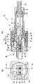
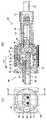
図1に、本発明による防水装置1の一例を外観斜視図で示す。本装置1は、互いに接続され得るプラグコネクタ(防水コネクタ)10とレセプタクルコネクタ(相手コネクタ)80の対から成る。図2は、プラグコネクタ10のみの分解斜視図を、図3は、図2のプラグコネクタ10とレセプタクルコネクタ80の中心線横断面図を、図4は、図3のA−A線縦断面図を、それぞれ示したものである。尚、便宜上、図1は、プラグコネクタ10とレセプタクルコネクタ80の接続前の状態を、図3、図4は、それらの接続後の状態を、それぞれ示している。 FIG. 1 is an external perspective view showing an example of a waterproof device 1 according to the present invention. The device 1 includes a pair of a plug connector (waterproof connector) 10 and a receptacle connector (mating connector) 80 that can be connected to each other. 2 is an exploded perspective view of only the
レセプタクルコネクタ80は、例えば、ネジ穴85を貫通させたネジ(図示されていない)によって壁面(図示されていない)に固定して使用する。レセプタクルコネクタ80との間に隙間を生じさせないように、レセプタクルコネクタ80のRシェル82に円環状の窪み92を設け、そこにOリング83を配置できる。Oリング83を設けることによって、レセプタクルコネクタ80との間に生じ得る隙間を塞ぎ、水の流入をより確実に防止できる。 The
プラグコネクタ10とレセプタクルコネクタ80の接続状態を維持するため、プラグコネクタ10とレセプタクルコネクタ80は、バイヨネット接続によって固定される。バイヨネットによる固定のため、レセプタクルコネクタ80の筒状部86の外面には、終端に窪み98を形成した固定溝90が対向位置に2つ設けられ、これに対応して、プラグコネクタ10の結合部材18の先端側内周面に、対向位置に突起36が2つ設けられている。筒状部86は、LCアダプタ(アダプタ部材)81の周囲を環状に取り囲むように、コネクタ部材12側に向かって張り出しており、プラグコネクタ10とレセプタクルコネクタ80のバイヨネットによる固定時には、この筒状部86の固定溝90に沿って結合部材18の突起36を図示矢印「ア1」方向に押し込み、次いで、結合部材18を筒状部86の外面に沿って「イ」方向に回動させ、結合部材18の突起36を筒状部86の窪み98に落とし込む。 In order to maintain the connection state between the
LCアダプタ81には、嵌合空間84が計4つ設けられている。各嵌合空間84によって、一方の側から挿入されるコネクタ部材12と、他方の側から挿入される、コネクタ部材12と略同形状のレセプタクルコネクタ部材と、を対向側から互いに突き合わせて嵌合させることができる。レセプタクルコネクタ80側の嵌合空間84に、コネクタ部材(図示されていない)によって支持した相手フェルールを配し、プラグコネクタ10側の嵌合空間に、コネクタ部材12を嵌合させることにより、レセプタクルコネクタ80側に配された相手フェルール(図示されていない)とプラグコネクタ10側のフェルール23とを、LCアダプタ81に設けた接続スリーブ91を通じて互いに突き合わせて光接続を行うことができる。これらフェルール23の端面には、ファイバ芯線40を露出させた状態で光ファイバ22が固定され、該光ファイバ22は、例えば、テンションメンバー(剛性コード部材)21とともにケーブル28の被覆29によって覆われた状態でコネクタ部材12の内部に入り込むように延長される。 The
プラグコネクタ10は、主に、筒状体として形成されたコードカン(基部)14と、このコードカン14に対して図2の図示矢印「エ」方向に順次に取り付けられる、引止金具13、スクロウェーブリング24、コネクタ部材12及びLCツマミ62、及びゴムフード11等と、更に、コードカン14に対して図2の図示矢印「オ」方向にて順次に取り付けられる、ガスケット15、コードクランプ16、締付金具17、及び結合部材18から成る。コードカン14に対応して、ゴムフード11、ガスケット15、コードクランプ16、締付金具17は、略円筒状とされている。 The
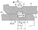
コネクタ部材12は、一例として、並置した2つの同形状のコネクタ部分12a、12bを含むものとして示されているが、これに限らず、コネクタ部分を1つのみとしてもよいし、3つ以上としてもよい。これらの各コネクタ部分は、一般に利用可能なLCコネクタと同様の構造を有する。故に、本構成は、一般のLCコネクタに幅広く利用できるものである。各コネクタ部分12a、12bには、それぞれ、斜後上方に延びる片持ち梁部(ロック操作部)61a、61bが形成されており、これらの各片持ち梁部61a、61bは、それらの両側面にロック用突部73a、73bを有する。これらのロック用突部73は、コネクタ部材12とLCアダプタ81の嵌合時に、LCアダプタ81の相補形状部(LCアダプタ81に設けた凹状の対応ロック部(図11に「87」で示す))に係止され、それらをロックする。この結果、フェルール23と相手フェルールの突き合わせは維持される。 As an example, the
よく知られているように、片持ち梁部61によるロックは、コネクタ部材12とLCアダプタ81とを互いに接近させることによって、特別な操作を行うことなく自動的に実行される。更に言えば、LCアダプタ81の受容部84a、84b(図3参照)への片持ち梁部61a、61bの挿入に伴い、片持ち梁部61a、61bは、LCアダプタ81との衝突を通じて自動的に下方に変位させられ、その後、ロック用突部73が対応ロック部87に受容された後に上方に自動復帰することにより、自動的にロックがなされる。これに対し、コネクタ部材12をLCアダプタ81から抜去する際は、コネクタ部材12のロック用突部73とLCアダプタ81のロックを解除するため、外部操作によって片持ち梁部61a、61bを下方に変位させつつ、コネクタ部材12をLCアダプタ81から引き抜く必要がある。通常、片持ち梁部61a、61bの、この下方への変位は、ユーザによる手動操作によって行われるが、本願発明では、後述するように、LCツマミ62(ロック解除手段)を設けることによって、他の部材と連動させるようにして、これを自動操作することができる。したがって、本願発明のプラグコネクタ10は、レセプタクルコネクタ80に対して、ワンタッチで接続、及び、接続の解除を行うことができる。 As is well known, the locking by the
コネクタ部材12の各コネクタ部分12a、12bは、相手フェルールとの突き合わせ方向(コネクタ部材12とLCアダプタ81との嵌合方向)に沿って所定の範囲で遊動可能な状態で、LCツマミ62に連結される。LCツマミ62とコネクタ部材12を遊動可能な状態で連結させるため、光ファイバ22、より詳細には、ガスケット15とコネクタ部材12との間には、ある程度の遊びが設けられている。LCツマミ62は、概略、前方に設けたフランジ65と、後方に設けた円筒部分75から成る。フランジ65の後面は、LCツマミ62とコードカン14の間に配した弾性部材であるスクロウェーブリング24と接触しており、この結果、LCツマミ62は常時、前側、つまりLCアダプタ81との嵌合側に付勢されている。 Each
LCツマミ62のフランジ65には、円筒部分75と連通した貫通穴69が設けられている。これらの貫通穴69及び円筒部分75には、コネクタ部材12の後端側68が挿通、支持される。コネクタ部材12は、これらに挿通、支持された状態で、LCアダプタ81との嵌合方向に沿って、LCツマミ62に対して遊動し得る。ただし、前方、即ち、レセプタクルコネクタ80側への移動は、コネクタ部材12の後端側に設けた板状の衝突用スペーサ64と、LCツマミ62の貫通穴69の後面74と、の衝突を通じて制限され、一方、後方、即ち、レセプタクルコネクタ80とは反対の側への移動は、コネクタ部材12の外側面の下部に設けた凸部66と、LCツマミ62の貫通穴69の前面72と、の衝突を通じて制限されている。故に、コネクタ部材12が、LCツマミ62から抜け落ちることはない。尚、スペーサ64は、図2に示すように、図示矢印「ウ」方向から取り付けることができる。 The
フランジ65の前側上部に、タブ67が設けられている。タブ67は、前方に張り出すとともに、更に、その前方の端部付近で下方、即ち、片持ち梁部61側に張り出しており、全体として、片持ち梁部61の自由端付近を包み込む形状を有している。タブ67を設けたことにより、LCツマミ62がコネクタ部材12に対して後側に移動したときは、片持ち梁部61a、61bが、自由端76とタブ67との接触を通じて下方に押し下げられ、この結果、コネクタ部材12とLCアダプタ81のロック状態は解除される。更に言えば、コネクタ部材12とLCアダプタ81のロック状態は、LCツマミ62をコネクタ部材12に対して後側に移動させることによって解除できるということである。 A
コードカン14は、便宜上、小径部50、中径部51、大径部52に分類できる。小径部50には、内部にケーブル28を挿通させた状態でガスケット15、コードクランプ16、締付金具17を取り付けられる。これによって、より完全な防水が実現され得る。小径部50の後方側の内径は拡径されており、この拡径部に、ガスケット15を挿入し、ケーブル28が挿通されたガスケット15を押し潰すようにコードクランプ16を取り付け、更に、コードクランプ16の後端に設けた弾性部58を押し潰して縮径するように締付金具17を取り付ける。締付金具17の後端内径は、弾性部58を押し潰してケーブル28を固定できるよう、後部に向かって小径とされており、そこに傾斜部57を形成している。尚、小径部50に対するコードクランプ16の位置決めを容易にするため、小径部50の内壁に位置決め用の切り欠き(図示されていない)を、これに対応して、コードクランプ16に位置決め用の突起56を、それぞれ設けてもよい。これらの全て取り付けたとき、小径部50の外面、及び、この小径部50から飛び出たコードクランプ16の後端の弾性部58は、それらの外面を締付金具17によって完全に覆われる。 The cord can 14 can be classified into a
中径部51は、LCツマミ62の円筒部分75を支持する。この円筒部分75は、中径部51の内径と略等しい外径を有し、中径部51の内部に遊嵌される。この結果、LCツマミ62は、コードカン14によって、フェルール23と相手フェルールとの突き合わせ方向(図示矢印「ア」方向)に沿って所定の範囲でスライド可能に支持される。また、中径部51の内部には板状の引止金具13が収容される。引止金具13は、中径部51の内径より小さな外径を有し、中径部51の内部に完全に挿入される。引止金具13には、テンションメンバー21の先端が挿入される割れ目63が設けてあり、この割れ目63にテンションメンバー21を挿入し、ネジ穴26を貫通させたネジ(図示されていない)を利用して、引止金具13とテンションメンバー21に固定できるようになっている。引止金具13にテンションメンバー21を固定することにより、例えば、テンションメンバー21が突き合わせ方向にてレセプタクルコネクタ80側とは反対の側に引っ張られたときであっても、引止金具13の後面45とコードカン14の後側内壁47が当接し、コードカン14に力が伝わるようにして、光ファイバ22に加わる力を軽減させることができる。 The
中径部51の先端側外周には、結合部材18の後板35を中径部51と大径部52の境目間付近に位置付けた後、C字状の抜止部材(スプリングワッシャー)19を取り付ける。抜止部材19は、中径部51によって支持した結合部材18の後板35と衝突して、結合部材18の中径部51からの抜け落ちを防止する。抜止部材19は、その弾性作用を利用して、中径部51に設けた環状C字状凹部32に嵌め込まれる。 A C-shaped retaining member (spring washer) 19 is attached to the outer periphery on the front end side of the
中径部51の先端側内周、且つ、抜止部材19の内側付近に、C字状のスプリングワッシャー(連結部材)20を取り付ける。取り付けは、抜止部材19同様、弾性作用を利用する。このスプリングワッシャー20は、LCツマミ62の円筒部分75の外壁38とコードカン14の内壁39のそれぞれに設けた環状外凹部30、環状内凹部33によって形成された空間60にまたがってそれらを連結し得る。環状外凹部30、環状内凹部33は、突き合わせ方向と交差する方向(図示矢印「カ」方向)に窪みを有し、特に、環状外凹部30は、突き合わせ方向に、スプリングワッシャー20よりも大きな長さ部分(図示矢印「キ」の部分)を有する。環状外凹部30のこの長さ部分を利用して、LCツマミ62は、コードカン14に対して所定の範囲でスライドし得る。尚、中径部51の後端部の一部には、スパナなどの工具により締めこむための平坦部53が対向位置に形成してある。なお、締付金具17にも同様の平坦部が設けられている。 A C-shaped spring washer (connecting member) 20 is attached to the inner periphery of the front end side of the
大径部52は、突き合わせ方向に沿ってレセプタクルコネクタ80の筒状部86側に張り出した筒部25を有する。コネクタ部材12とこれに連結されたLCツマミ62のフランジ65付近は、この筒部25の内部で、突き合わせ方向に沿って所定の範囲でスライドし得る。筒部25は、プラグコネクタ10とレセプタクルコネクタ80の固定時に、筒状部86の内周97と接触し、筒状部86との間に突き合わせ方向にて重なり部分88を形成し得る。このような重なり部分88を形成することにより、より効果的に防水を行うことができる。また、大径部52には、中径部51を貫通させた略筒状の結合部材18が遊嵌される。結合部材18は、フェルール23と相手フェルールの突き合わせ方向に沿ってレセプタクルコネクタ80側に張り出した略筒状の部材であって、大径部52の外周を覆い、且つ、プラグコネクタ10とレセプタクルコネクタ80の固定時には、上述した方法でレセプタクルコネクタ80側の筒状部86にバイヨネット接続によって接続される。プラグコネクタ10とレセプタクルコネクタ80の固定時に、レセプタクルコネクタ80の筒状部86は、プラグコネクタ10の筒部25と結合部材18との間に形成された隙間99に挟み込まれた状態で配置される。更に、結合部材18は、筒状部86の外周96を覆い、且つ、筒部25と同様に、筒状部86との間に突き合わせ方向にて重なり部分87を形成し得る。このような構成により、防水を確実に行うことができる。結合部材18と大径部52の間に形成された隙間99に設けたゴムフード11も、防水効果を高める。ゴムフード11は、大径部52の一部を構成する筒部25のフランジ27にその後面を突き当てるとともに、筒部25に設けた位置決め用の環状窪み54によって位置決めされる。プラグコネクタ10とレセプタクルコネクタ80の接続時には、ゴムフード11の先端に設けた盛り上げ部41が、筒状部86の薄肉部89と密着し、これにより、隙間をより完全に塞ぐことができるようになっている。 The large-
最後に、図5乃至図20を参照して、本装置1の作用を説明する。図5乃至図12は、プラグコネクタ10とレセプタクルコネクタ80の接続時、言い換えれば、コネクタ部材12とLCアダプタ81の嵌合時のシーケンス、一方、図13乃至図20は、プラグコネクタ10とレセプタクルコネクタ80の接続の解除時、言い換えれば、LCアダプタ81からのコネクタ部材12の抜去時のシーケンスを、それぞれ示す図である。 Finally, the operation of the present apparatus 1 will be described with reference to FIGS. 5 to 12 show a sequence when the
ここで、図5等の各図中の(a)は、(b)に示した縦断面の断面位置を示す図であり、便宜上、プラグコネクタ10とレセプタクルコネクタ80の接続時(コネクタ部材12とLCアダプタ81の嵌合時)の状態を示している。尚、各図中の(a)に示す断面位置が同じ場合には、同じ符号を使用している。例えば、図5の(a)に示すA−A線断面位置は、図7の(a)に示すA−A線断面位置と同じであるが、図9の(a)に示すD−D線断面位置とは異なるということである。更に、図6等は、図5等の各図中の(b)に示す部分拡大図を示す。更に詳細には、図6は図5のB部分における部分拡大図、図8は図7のC部分における部分拡大図、図10は図9のE部分における部分拡大図、図12は図11のG部分における部分拡大図、図14は図13のH部分における部分拡大図、図16は図15のI部分における部分拡大図、図18は図17のJ部分における部分拡大図、図20は図19のK部分における部分拡大図である。 Here, (a) in each figure such as FIG. 5 is a diagram showing a cross-sectional position of the longitudinal section shown in (b). For convenience, when the
図5乃至図12等を参照して、プラグコネクタ10とレセプタクルコネクタ80の接続時における動作を説明する。
1)先ず、図5、図6に示すように、コードカン14を、LCアダプタ81との嵌合方向に沿ってレセプタクルコネクタ80側(図示矢印「ア1」方向)に移動させることにより、コードカン14によって支持された結合部材18を、筒状部86に接近させた状態にするとともに、コードカン14の凹部33の内壁後面77を、スプリングワッシャー20の後面48に当接させ、スプリングワッシャー20をコードカン14と一体的に移動させる。
2)図7、図8に示すように、さらにコードカン14をレセプタクルコネクタ80側に移動させることで、スプリングワッシャー20の前面49を、LCツマミ62の凹部30の内壁前面70に当接させ、スプリングワッシャー20を介して、コードカン14によって支持されたLCツマミ62を、コネクタ部材12に向かって移動させる。
3)図9、図10に示すように、さらにコードカン14をレセプタクルコネクタ80側に移動させ、コネクタ部材12の外側面に設けた凸部66とLCツマミ62の貫通穴69の前面72を衝突させ、この衝突を利用して、LCツマミ62によって支持されたコネクタ部材12を、LCアダプタ81に接近させる。
4)図11、図12に示すように、さらに移動させることで、コネクタ部材12の片持ち梁部61とLCアダプタ81の対応ロック部87が弾性変位作用によって係合し、コネクタ部材12とLCアダプタ81の嵌合、ロックがなされる。
5)最後に、結合部材18を時計回り(図中矢印「イ」方向)に回転させてバイヨネット方式にて筒状部86に固定する。The operation when the
1) First, as shown in FIGS. 5 and 6, the cord can 14 is moved toward the receptacle connector 80 (in the direction of the arrow “a1” in the figure) along the fitting direction with the
2) As shown in FIGS. 7 and 8, the cord can 14 is further moved to the
3) As shown in FIGS. 9 and 10, the cord can 14 is further moved to the
4) As shown in FIGS. 11 and 12, by further moving, the
5) Finally, the
次いで、図13乃至図20等を参照して、プラグコネクタ10とレセプタクルコネクタ80の接続の解除時における動作を説明する。
1)先ず、結合部材18を反時計回り(図中矢印「イ」の反対方向)に回転させて筒状部86の固定を解除する。
2)その後、図13、図14に示すように、コードカン14を、LCアダプタ81との嵌合方向に沿ってレセプタクルコネクタ80側とは反対の側(図示矢印「ア2」方向)に移動させ、これによって、コードカン14によって支持された結合部材18を筒状部86から引き離すととともに、コードカン14の凹部33の内壁前面78を、スプリングワッシャー20の前面49に当接させ、スプリングワッシャー20をコードカン14と一体的に移動させる。
3)図15、図16に示すように、さらにコードカン14をレセプタクルコネクタ80側とは反対の側に移動させることで、スプリングワッシャー20の後面48を、LCツマミ62の凹部30の内壁後面71に当接させ、スプリングワッシャー20を介して、コードカン14によって支持されたLCツマミ62をコネクタ部材12から引き離す。
4)この結果、図17、図18に示すように、LCツマミ62のタブ67と片持ち梁部61の自由端76とが接触し、この接触を通じて、片持ち梁部61が下方(図示矢印「カ」方向)に押し下げられ、LCアダプタ81とコネクタ部材12のロックが解除される。
5)図19、図20に示すように、さらにコードカン14をレセプタクルコネクタ80側とは反対の側に移動させることにより、コネクタ部材12の後端側に設けた衝突部材64とLCツマミ62の貫通穴69の後面74が衝突し、この衝突を利用して、LCツマミ62によって支持されたコネクタ部材12がLCアダプタ81から引き離され、コネクタ部材12とLCアダプタ81の嵌合が解除される。Next, with reference to FIGS. 13 to 20 and the like, an operation at the time of releasing the connection between the
1) First, the
2) After that, as shown in FIGS. 13 and 14, the cord can 14 is moved to the side opposite to the
3) As shown in FIGS. 15 and 16, the cord can 14 is further moved to the side opposite to the
4) As a result, as shown in FIGS. 17 and 18, the
5) As shown in FIGS. 19 and 20, the cord can 14 is further moved to the side opposite to the
このような本願発明の構成によれば、プラグコネクタ10とレセプタクルコネクタ80との接続時には、コードカン14をコネクタ部材12に対して移動させる1つの作業を通じて、コネクタ部材12とLCアダプタ81を嵌合させるとともに、結合部材18と筒状部86を接続(或いは、その後のバイヨネット接続による固定)させることができ、逆に、プラグコネクタ10とレセプタクルコネクタ80との接続の解除時には、コードカン14をコネクタ部材12に対して移動させる1つの作業を通じて、結合部材18と筒状部86のバイヨネット接続の解除を行うとともに、コネクタ部材12とLCアダプタ81の嵌合を解除することができる。このように、本願発明のプラグコネクタ10は、バイヨネットロックを解除することを目的としてカップリングを回転させる必要はあるものの、レセプタクルコネクタ80に対してワンタッチで接続、及び、接続の解除を行うことができ、特に、プラグコネクタ10に設けたコネクタ部材12のロック解除は「引き抜く動作」のみで達成できるため、作業性に非常に優れたものということができる。また、コネクタ部材12とLCアダプタ81の嵌合は、LCツマミ62を用いるものの、通常と同様の方法で解除されることから、ロックの解除も確認し易いという利点もある。 According to such a configuration of the present invention, when the
防水コネクタに限らず、他の様々なコネクタにも応用することができる。 Not only a waterproof connector but also various other connectors can be applied.
1 防水装置
10 プラグコネクタ(防水コネクタ)
12 コネクタ部材(LCコネクタ)
14 基部(コードカン)
18 カップリング(結合部材)
20 スプリングワッシャー(連結部材)
23 フェルール
24 スクロウェーブリング(弾性部材)
30 凹部
33 凹部
45 後面
47 後側内壁
48 後面
49 前面
60 空間
61 ロック操作部
62 LCツマミ(ロック解除手段)
80 レセプタクルコネクタ(相手コネクタ)
81 LCアダプタ(アダプタ部材)1
12 Connector member (LC connector)
14 Base (code can)
18 Coupling (coupling member)
20 Spring washer (connecting member)
23
30
80 Receptacle connector (mating connector)
81 LC adapter (Adapter member)
Claims (15)
Translated fromJapanese前記コネクタ部材を前記フェルールと前記相手フェルールとの突き合わせ方向に沿って所定の範囲で遊動可能に支持し、前記突き合わせ方向に沿って前記相手コネクタ側とは反対の側に移動したときに前記コネクタ部材に設けた前記ロック操作部を操作して前記コネクタ部材と前記アダプタ部材のロックを解除することができる、ロック解除手段と、
前記突き合わせ方向に沿って前記相手コネクタ側に張り出し、前記アダプタ部材の周囲を前記突き合わせ方向に沿って取り囲むように前記コネクタ部材側に前記相手コネクタから張り出した筒状部に固定可能であって、前記筒状部に固定された際に前記筒状部との間に前記突き合わせ方向にて重なり部分を形成し得る、略筒状の結合部材と、
前記結合部材を支持し、且つ、前記ロック解除手段を前記突き合わせ方向に沿って所定の範囲でスライド可能に支持する基部と、を備え、
前記相手コネクタとの接続時には、前記基部を前記突き合わせ方向に沿って前記相手コネクタ側に移動させることにより、前記基部によって支持された前記結合部材を前記筒状部に接近させるとともに、前記基部によって支持された前記ロック解除手段を、前記ロック解除手段によって支持された前記コネクタ部材に接近させ、その後、前記ロック解除手段によって支持された前記コネクタ部材を、前記アダプタ部材に接近させて前記コネクタ部材と前記アダプタ部材を嵌合させた後、前記基部を前記突き合わせ方向に沿ってスライドさせつつ前記結合部材を前記筒状部に固定するようになっており、
前記相手コネクタとの接続の解除時には、前記基部を前記突き合わせ方向に沿ってスライドさせつつ前記結合部材と前記筒状部の固定を解除した後、前記基部を前記突き合わせ方向に沿って前記相手コネクタ側とは反対の側に移動させることにより、前記基部によって支持された前記結合部材を前記筒状部から引き離すととともに、前記基部によって支持された前記ロック解除手段を、前記ロック解除手段によって支持された前記コネクタ部材から引き離し、これにより、前記コネクタ部材に設けた前記ロック操作部を前記ロック解除手段で操作して前記アダプタ部材と前記コネクタ部材のロックを解除するとともに、前記ロック解除手段によって支持された前記コネクタ部材を前記アダプタ部材から引き離して、前記コネクタ部材と前記アダプタ部材の嵌合を解除することを特徴とする防水コネクタ。Supports a ferrule that can be abutted against the mating ferrule disposed on the mating connector, and is detachably fitted to an adapter member that supports the mating ferrule disposed on the mating connector so that the ferrule butts against the mating ferrule A connector member that can be locked to the adapter member so as to maintain a match between the ferrule and the counterpart ferrule by the action of a lock operating portion provided in the connector member;
The connector member supports the connector member so as to be freely movable within a predetermined range along the abutting direction of the ferrule and the mating ferrule, and moves to the side opposite to the mating connector side along the abutting direction. Unlocking means that can unlock the connector member and the adapter member by operating the lock operating portion provided in
It projects to the mating connector side along the abutting direction, and can be fixed to a tubular portion projecting from the mating connector to the connector member side so as to surround the adapter member along the abutting direction, A substantially cylindrical coupling member capable of forming an overlapping portion in the butting direction with the cylindrical portion when fixed to the cylindrical portion;
A base that supports the coupling member and supports the unlocking means slidably within a predetermined range along the abutting direction;
At the time of connection with the mating connector, the base is moved toward the mating connector along the abutting direction so that the coupling member supported by the base approaches the cylindrical portion and is supported by the base. The unlocking means is moved closer to the connector member supported by the unlocking means, and then the connector member supported by the unlocking means is moved closer to the adapter member and the connector member and the After fitting the adapter member, the coupling member is fixed to the tubular portion while sliding the base portion along the butting direction,
When releasing the connection with the mating connector, the base member is slid along the abutting direction while releasing the coupling member and the cylindrical portion, and then the base is moved along the abutting direction to the mating connector side. By moving the coupling member supported by the base portion away from the cylindrical portion, the unlocking means supported by the base portion is supported by the unlocking means. Pulled away from the connector member, thereby operating the lock operating portion provided on the connector member with the unlocking means to unlock the adapter member and the connector member, and supported by the unlocking means. Pulling the connector member away from the adapter member, the connector member and the adapter Waterproof connector, characterized in that to release the engagement of the descriptor member.
前記防水コネクタと前記相手コネクタの接続時に、前記結合部材は前記筒状部の外周を覆い、前記相手コネクタの前記筒状部は、前記結合部材と前記防水コネクタの前記筒部との間に形成された隙間に挟み込まれる請求項1乃至10のいずれかに記載の防水コネクタ。The base portion protrudes toward the mating connector in the abutting direction so that an overlapping portion can be formed in the abutting direction between the base portion and the inner periphery of the cylindrical portion when fixed to the cylindrical portion. Having a cylinder part,
When the waterproof connector and the mating connector are connected, the coupling member covers an outer periphery of the cylindrical portion, and the cylindrical portion of the mating connector is formed between the coupling member and the cylindrical portion of the waterproof connector. The waterproof connector according to claim 1, wherein the waterproof connector is sandwiched between the formed gaps.
前記コネクタ部材を前記フェルールと前記相手フェルールとの突き合わせ方向に沿って遊動可能に支持し、前記突き合わせ方向に沿って前記相手コネクタ側とは反対の側に移動したときに前記コネクタ部材に設けた前記ロック操作部を操作して前記コネクタ部材と前記アダプタ部材のロックを解除することができる、ロック解除手段と、
前記ロック解除手段を前記突き合わせ方向に沿ってスライド可能に支持する基部と、を備え、
前記相手コネクタとの接続時には、前記基部を前記突き合わせ方向に沿って前記相手コネクタ側に移動させることにより、前記基部によって支持された前記ロック解除手段を、前記コネクタ部材に接近させ、その後、前記ロック解除手段によって支持された前記コネクタ部材を、前記アダプタ部材に接近させて前記コネクタ部材と前記アダプタ部材を嵌合させるようになっており、
前記相手コネクタとの接続の解除時には、前記基部を前記突き合わせ方向に沿って前記相手コネクタ側とは反対の側に移動させることにより、前記基部によって支持された前記ロック解除手段を、前記ロック解除手段によって支持された前記コネクタ部材から引き離し、これにより、前記コネクタ部材に設けた前記ロック操作部を前記ロック解除手段で操作して前記アダプタ部材と前記コネクタ部材のロックを解除するとともに、前記ロック解除手段によって支持された前記コネクタ部材を前記アダプタ部材から引き離して、前記コネクタ部材と前記アダプタ部材の嵌合を解除することを特徴とする防水コネクタ。A connector member that supports a ferrule that can be abutted against each other with a mating ferrule disposed on the mating connector, and can be locked to the adapter member so as to maintain the butting of the ferrule and the mating ferrule by the action of a lock operation unit;
The connector member is movably supported along the abutting direction of the ferrule and the mating ferrule, and provided on the connector member when moved to the side opposite to the mating connector side along the abutting direction. A lock release means capable of operating the lock operation portion to unlock the connector member and the adapter member;
A base that slidably supports the unlocking means along the abutting direction, and
At the time of connection with the mating connector, the unlocking means supported by the base is moved closer to the connector member by moving the base toward the mating connector along the butting direction, and then the lock The connector member supported by the release means is brought close to the adapter member to fit the connector member and the adapter member,
When releasing the connection with the mating connector, the unlocking means supported by the base is moved to the side opposite to the mating connector side along the abutting direction, so that the unlocking means is supported by the unlocking means. The lock member is pulled away from the connector member supported by the connector member, whereby the lock operation unit provided on the connector member is operated by the lock release unit to unlock the adapter member and the connector member, and the lock release unit. The connector member supported by the connector is pulled away from the adapter member to release the fitting between the connector member and the adapter member.
Priority Applications (5)
| Application Number | Priority Date | Filing Date | Title |
|---|---|---|---|
| JP2009044378AJP4743724B2 (en) | 2009-02-26 | 2009-02-26 | Waterproof connector and waterproof device using the waterproof connector |
| US12/709,299US8628252B2 (en) | 2009-02-26 | 2010-02-19 | Waterproof connector and waterproof device using the same |
| EP20100001857EP2253977B1 (en) | 2009-02-26 | 2010-02-23 | Waterproof connector and waterproof device using the same |
| AT10001857TATE557308T1 (en) | 2009-02-26 | 2010-02-23 | WATERPROOF CONNECTOR AND WATERPROOF DEVICE USING SUCH CONNECTOR |
| CN2010101261778ACN101820118B (en) | 2009-02-26 | 2010-02-24 | Waterproof connector and waterproof device using the same |
Applications Claiming Priority (1)
| Application Number | Priority Date | Filing Date | Title |
|---|---|---|---|
| JP2009044378AJP4743724B2 (en) | 2009-02-26 | 2009-02-26 | Waterproof connector and waterproof device using the waterproof connector |
Publications (2)
| Publication Number | Publication Date |
|---|---|
| JP2010197854A JP2010197854A (en) | 2010-09-09 |
| JP4743724B2true JP4743724B2 (en) | 2011-08-10 |
Family
ID=42631033
Family Applications (1)
| Application Number | Title | Priority Date | Filing Date |
|---|---|---|---|
| JP2009044378AActiveJP4743724B2 (en) | 2009-02-26 | 2009-02-26 | Waterproof connector and waterproof device using the waterproof connector |
Country Status (5)
| Country | Link |
|---|---|
| US (1) | US8628252B2 (en) |
| EP (1) | EP2253977B1 (en) |
| JP (1) | JP4743724B2 (en) |
| CN (1) | CN101820118B (en) |
| AT (1) | ATE557308T1 (en) |
Families Citing this family (53)
| Publication number | Priority date | Publication date | Assignee | Title |
|---|---|---|---|---|
| EP2302431B1 (en) | 2009-09-28 | 2019-03-27 | TE Connectivity Nederland B.V. | Sealing enclosure for a connector on a cable, such as a standardised fibre-optic connector |
| PL2355286T3 (en) | 2010-01-29 | 2019-10-31 | CommScope Connectivity Belgium BVBA | Cable sealing and retaining device |
| EP2355283A1 (en) | 2010-01-29 | 2011-08-10 | Tyco Electronics Raychem BVBA | Cable sealing device, cable termination and attaching device |
| US8727636B2 (en)* | 2010-03-19 | 2014-05-20 | Corning Incorporated | Fiber optic interface device with positionable cleaning cover |
| JP5707808B2 (en)* | 2010-09-21 | 2015-04-30 | 富士通株式会社 | Coupling device |
| JP5505228B2 (en)* | 2010-09-24 | 2014-05-28 | 富士通株式会社 | Optical connector |
| CN103314483A (en)* | 2011-02-04 | 2013-09-18 | 株式会社藤仓 | Terminal block |
| US8764308B2 (en) | 2011-06-06 | 2014-07-01 | Panduit Corp. | Duplex clip assembly for fiber optic connectors |
| CN103123408B (en)* | 2011-11-21 | 2015-04-15 | 鸿富锦精密工业(深圳)有限公司 | Waterproof optical fiber connector and optical fiber plug and optical fiber adapter thereof |
| DE102012202225B4 (en)* | 2012-02-14 | 2015-10-22 | Te Connectivity Germany Gmbh | Plug housing with seal |
| JP6201222B2 (en) | 2012-06-26 | 2017-09-27 | ▲ホア▼▲ウェイ▼技術有限公司Huawei Technologies Co.,Ltd. | Optical fiber connector, optical fiber adapter, and optical fiber connector assembly |
| JP5890273B2 (en)* | 2012-07-27 | 2016-03-22 | 日本航空電子工業株式会社 | Plug and optical connector connector |
| US20140060927A1 (en)* | 2012-08-30 | 2014-03-06 | Avc Industrial Corp. | Hook-thread component and wiring element fastening device having the hook-thread component |
| JP5866734B2 (en)* | 2012-12-27 | 2016-02-17 | ヒロセ電機株式会社 | Connector, connector device using the connector, and connector member used for the connector |
| KR101330648B1 (en) | 2013-05-22 | 2013-11-18 | 주식회사 케이오티 | A outdoor optical connector assembly using multiple cores mt ferrule |
| US9235010B2 (en)* | 2013-06-28 | 2016-01-12 | Commscope Technologies Llc | Robust optical crimp connector |
| KR101513850B1 (en)* | 2013-10-16 | 2015-04-21 | 전자부품연구원 | Waterproof optical connector with improved structure |
| WO2015063148A1 (en) | 2013-10-31 | 2015-05-07 | Tyco Electronics Raychem Bvba | Fiber optic connection system |
| KR101512997B1 (en)* | 2014-01-03 | 2015-04-17 | 주식회사 제이티 | Water-proof optical connector having double locking structure |
| KR101560140B1 (en) | 2014-01-13 | 2015-10-14 | 주식회사 제이티 | Water-proof optical connector |
| CN109343178A (en) | 2014-02-07 | 2019-02-15 | 泰科电子公司 | Hardened optical power connection system |
| CA2887523C (en)* | 2014-04-14 | 2017-08-29 | Fujikura, Ltd. | Optical connector |
| GB2526369B (en) | 2014-05-23 | 2019-06-26 | Itt Mfg Enterprises Llc | Electrical connector |
| CN104348036B (en)* | 2014-10-21 | 2017-07-14 | 河南天海电器有限公司 | New connector |
| CN204359965U (en)* | 2014-11-20 | 2015-05-27 | 泰科电子(上海)有限公司 | Connector system |
| US9755382B2 (en) | 2015-03-13 | 2017-09-05 | Senko Advanced Components, Inc. | Connector system with interchangeable connector modules for optical fibers, electrical conductors, or both |
| EP3705920A1 (en) | 2015-04-03 | 2020-09-09 | CommScope Connectivity Belgium BVBA | Low cost hardened fiber optic connection system |
| US11175466B2 (en)* | 2015-07-02 | 2021-11-16 | Senko Advanced Components, Inc. | Bayonet lock MPO connector |
| US9726831B2 (en) | 2015-07-02 | 2017-08-08 | Senko Advanced Components, Inc. | Bayonet lock MPO connector |
| WO2017003934A1 (en) | 2015-07-02 | 2017-01-05 | Senko Advanced Components, Inc. | Bayonet lock mpo connector |
| US9897766B2 (en) | 2015-07-02 | 2018-02-20 | Senko Advanced Components, Inc. | Bayonet lock MPO connector |
| JP2017090657A (en)* | 2015-11-10 | 2017-05-25 | ヒロセ電機株式会社 | Connector with optical fiber cable |
| WO2017200882A1 (en)* | 2016-05-18 | 2017-11-23 | Canon U.S.A., Inc. | Apparatus and method for remotely engaging and disengaging a connector |
| MX2019003561A (en)* | 2016-09-30 | 2020-01-21 | Huawei Tech Co Ltd | Optical fiber sub-assembly, optical fiber adapter, and optical fiber connector. |
| CN108023205A (en)* | 2016-10-31 | 2018-05-11 | 全亿大科技(佛山)有限公司 | Water-proof connector and its assemble method |
| US10128607B2 (en)* | 2017-02-23 | 2018-11-13 | Te Connectivity Corporation | Sealed connector system |
| US10295759B2 (en) | 2017-05-18 | 2019-05-21 | Senko Advanced Components, Inc. | Optical connector with forward-biasing projections |
| CN109286100B (en)* | 2017-07-21 | 2021-06-04 | 泰科电子(上海)有限公司 | electrical connector |
| EP3460548A1 (en) | 2017-09-25 | 2019-03-27 | Fujikura Ltd. | Clamp member, optical connector, and manufacturing method of optical connector |
| US10444442B2 (en) | 2017-11-03 | 2019-10-15 | Senko Advanced Components, Inc. | MPO optical fiber connector |
| FI3677938T3 (en)* | 2017-12-28 | 2023-10-09 | Fujikura Ltd | Optical connector and method for connecting optical connector |
| JP2019140046A (en)* | 2018-02-15 | 2019-08-22 | 住友電装株式会社 | Connector, connector device |
| US11041993B2 (en) | 2018-04-19 | 2021-06-22 | Senko Advanced Components, Inc. | Fiber optic adapter with removable insert for polarity change and removal tool for the same |
| US10921528B2 (en) | 2018-06-07 | 2021-02-16 | Senko Advanced Components, Inc. | Dual spring multi-fiber optic connector |
| US10522946B1 (en)* | 2018-09-17 | 2019-12-31 | Hewlett Packard Enterprise Development Lp | Connectors with locking tab |
| CN111596414B (en) | 2019-02-20 | 2022-04-26 | 利佳科技股份有限公司 | Connector system |
| EP3977569A1 (en)* | 2019-05-24 | 2022-04-06 | Nokia Shanghai Bell Co., Ltd. | Communication system connector |
| WO2021026482A1 (en)* | 2019-08-08 | 2021-02-11 | Senko Advanced Components, Inc | Push pull mechanism for an outdoor rated connector assembly |
| US11353664B1 (en) | 2019-08-21 | 2022-06-07 | Senko Advanced Components, Inc. | Fiber optic connector |
| WO2021097304A1 (en) | 2019-11-13 | 2021-05-20 | Senko Advanced Components, Inc. | Fiber optic connector |
| IT202000001519A1 (en)* | 2020-01-27 | 2021-07-27 | Prysmian Spa | One optical connector adapter assembly |
| CN111679376B (en)* | 2020-04-23 | 2022-05-17 | 中航光电科技股份有限公司 | Connector with a locking member |
| CN114690340A (en)* | 2022-02-14 | 2022-07-01 | 大连光洋科技集团有限公司 | Waterproof structure capable of enabling SFP optical module to be used in humid environment |
Family Cites Families (12)
| Publication number | Priority date | Publication date | Assignee | Title |
|---|---|---|---|---|
| GB9307488D0 (en)* | 1993-04-08 | 1993-06-02 | Amp Holland | Optical fibre connector latching mechanism |
| US6644868B2 (en) | 1997-11-13 | 2003-11-11 | Diamond Sa | Plug construction for an optical plug-and-socket connection |
| JP3362014B2 (en)* | 1999-06-29 | 2003-01-07 | エヌイーシートーキン株式会社 | Lock and unlock structure of cable connector and method of locking and unlocking |
| US6565262B2 (en) | 2000-12-14 | 2003-05-20 | Corning Cable Systems Llc | Trigger mechanism, optical cable connector including same, and method of assembling an optical cable connector |
| JP2004258094A (en)* | 2003-02-24 | 2004-09-16 | Hitachi Cable Ltd | Package with release mechanism |
| JP2004318048A (en)* | 2003-08-22 | 2004-11-11 | Canare Electric Co Ltd | Female plug of optical connector |
| US7074066B2 (en)* | 2004-03-29 | 2006-07-11 | Tyco Electronics Corporation | Sealed electrical connector having internal latching mechanism therefore |
| US7234877B2 (en) | 2004-10-27 | 2007-06-26 | Panduit Corp. | Fiber optic industrial connector |
| US7325980B2 (en) | 2005-08-26 | 2008-02-05 | Tyco Electronics Corporation | Duplex style fiber optic connector interface assembly |
| US7338214B1 (en) | 2006-08-25 | 2008-03-04 | Tyco Electronics Corporation | Method and apparatus for sealing fiber optic connectors for industrial applications |
| JP4776504B2 (en)* | 2006-11-15 | 2011-09-21 | 富士通株式会社 | Auxiliary release releasing device for optical connector and printed circuit board device |
| WO2008128940A1 (en) | 2007-04-20 | 2008-10-30 | Huber + Suhner Ag | Optical connector |
- 2009
- 2009-02-26JPJP2009044378Apatent/JP4743724B2/enactiveActive
- 2010
- 2010-02-19USUS12/709,299patent/US8628252B2/enactiveActive
- 2010-02-23ATAT10001857Tpatent/ATE557308T1/enactive
- 2010-02-23EPEP20100001857patent/EP2253977B1/ennot_activeNot-in-force
- 2010-02-24CNCN2010101261778Apatent/CN101820118B/ennot_activeExpired - Fee Related
Also Published As
| Publication number | Publication date |
|---|---|
| EP2253977A2 (en) | 2010-11-24 |
| CN101820118B (en) | 2012-11-07 |
| EP2253977A3 (en) | 2011-07-13 |
| ATE557308T1 (en) | 2012-05-15 |
| JP2010197854A (en) | 2010-09-09 |
| US8628252B2 (en) | 2014-01-14 |
| US20100215322A1 (en) | 2010-08-26 |
| EP2253977B1 (en) | 2012-05-09 |
| CN101820118A (en) | 2010-09-01 |
Similar Documents
| Publication | Publication Date | Title |
|---|---|---|
| JP4743724B2 (en) | Waterproof connector and waterproof device using the waterproof connector | |
| JP4577793B2 (en) | Waterproof connector and waterproof device using the waterproof connector | |
| JP2011107513A (en) | Waterproof connector and waterproofing apparatus using the same | |
| JP4566932B2 (en) | Optical connector | |
| EP2037543A1 (en) | Electrical connector and connector assembly | |
| JP5391137B2 (en) | Ball lock connector | |
| JP6411002B1 (en) | Ball-lock type connector with an accidental detachment prevention mechanism | |
| JP2019028425A (en) | Optical connector plug and double-series optical connector plug | |
| JP5100869B2 (en) | Optical connector plug | |
| CA2722495A1 (en) | Optical connector and insertion and removal method of optical connector | |
| JP2007537462A (en) | Waterproof electrical connector with internal latch mechanism | |
| CN102016670A (en) | Plug connector with unlocking mechanism | |
| JP2015227938A (en) | Optical connector | |
| WO2021134971A1 (en) | Connector and optical fiber connection assembly | |
| WO2016056271A1 (en) | Plug having built-in connector | |
| CN112424661A (en) | Optical connector | |
| US11422315B2 (en) | Optical connector system | |
| JP4327063B2 (en) | Optical connector with shutter | |
| JP2015148735A (en) | Lc optical connector plug | |
| JP2020046582A (en) | Lc uni-boot plug connector | |
| CN108138831B (en) | connection construction | |
| JP5866734B2 (en) | Connector, connector device using the connector, and connector member used for the connector | |
| JP5398560B2 (en) | Optical connector and assembly method thereof | |
| JP5690005B1 (en) | Optical connector | |
| JP6077797B2 (en) | Optical connector |
Legal Events
| Date | Code | Title | Description |
|---|---|---|---|
| A711 | Notification of change in applicant | Free format text:JAPANESE INTERMEDIATE CODE: A712 Effective date:20100811 | |
| RD04 | Notification of resignation of power of attorney | Free format text:JAPANESE INTERMEDIATE CODE: A7424 Effective date:20101110 | |
| A621 | Written request for application examination | Free format text:JAPANESE INTERMEDIATE CODE: A621 Effective date:20110119 | |
| A977 | Report on retrieval | Free format text:JAPANESE INTERMEDIATE CODE: A971007 Effective date:20110412 | |
| TRDD | Decision of grant or rejection written | ||
| A01 | Written decision to grant a patent or to grant a registration (utility model) | Free format text:JAPANESE INTERMEDIATE CODE: A01 Effective date:20110418 | |
| A01 | Written decision to grant a patent or to grant a registration (utility model) | Free format text:JAPANESE INTERMEDIATE CODE: A01 | |
| A61 | First payment of annual fees (during grant procedure) | Free format text:JAPANESE INTERMEDIATE CODE: A61 Effective date:20110502 | |
| FPAY | Renewal fee payment (event date is renewal date of database) | Free format text:PAYMENT UNTIL: 20140520 Year of fee payment:3 | |
| R150 | Certificate of patent or registration of utility model | Ref document number:4743724 Country of ref document:JP Free format text:JAPANESE INTERMEDIATE CODE: R150 Free format text:JAPANESE INTERMEDIATE CODE: R150 | |
| R250 | Receipt of annual fees | Free format text:JAPANESE INTERMEDIATE CODE: R250 | |
| R250 | Receipt of annual fees | Free format text:JAPANESE INTERMEDIATE CODE: R250 | |
| R250 | Receipt of annual fees | Free format text:JAPANESE INTERMEDIATE CODE: R250 | |
| R250 | Receipt of annual fees | Free format text:JAPANESE INTERMEDIATE CODE: R250 | |
| R250 | Receipt of annual fees | Free format text:JAPANESE INTERMEDIATE CODE: R250 | |
| R250 | Receipt of annual fees | Free format text:JAPANESE INTERMEDIATE CODE: R250 | |
| R250 | Receipt of annual fees | Free format text:JAPANESE INTERMEDIATE CODE: R250 | |
| S531 | Written request for registration of change of domicile | Free format text:JAPANESE INTERMEDIATE CODE: R313531 | |
| R350 | Written notification of registration of transfer | Free format text:JAPANESE INTERMEDIATE CODE: R350 | |
| R250 | Receipt of annual fees | Free format text:JAPANESE INTERMEDIATE CODE: R250 | |
| R250 | Receipt of annual fees | Free format text:JAPANESE INTERMEDIATE CODE: R250 | |
| R250 | Receipt of annual fees | Free format text:JAPANESE INTERMEDIATE CODE: R250 | |
| R250 | Receipt of annual fees | Free format text:JAPANESE INTERMEDIATE CODE: R250 | |
| R250 | Receipt of annual fees | Free format text:JAPANESE INTERMEDIATE CODE: R250 |