JP4743133B2 - Electronic component mounting apparatus and control program update method in electronic component mounting apparatus - Google Patents
Electronic component mounting apparatus and control program update method in electronic component mounting apparatusDownload PDFInfo
- Publication number
- JP4743133B2 JP4743133B2JP2007037571AJP2007037571AJP4743133B2JP 4743133 B2JP4743133 B2JP 4743133B2JP 2007037571 AJP2007037571 AJP 2007037571AJP 2007037571 AJP2007037571 AJP 2007037571AJP 4743133 B2JP4743133 B2JP 4743133B2
- Authority
- JP
- Japan
- Prior art keywords
- electronic component
- control program
- component mounting
- mounting apparatus
- unit
- Prior art date
- Legal status (The legal status is an assumption and is not a legal conclusion. Google has not performed a legal analysis and makes no representation as to the accuracy of the status listed.)
- Expired - Fee Related
Links
Images


Landscapes
- Supply And Installment Of Electrical Components (AREA)
- Stored Programmes (AREA)
Description
Translated fromJapanese本発明は、電子部品を基板に実装する電子部品実装システムを構成する電子部品実装用装置ならびにこの電子部品実装用装置における制御プログラムの更新方法に関するものである。 The present invention relates to an electronic component mounting apparatus constituting an electronic component mounting system for mounting an electronic component on a substrate, and a control program updating method in the electronic component mounting apparatus.
電子部品実装システムを構成する電子部品実装用装置の動作制御用のプログラムソフトは一般に、装置稼動開始以降においてもデバッグや改善の目的で頻繁に内容が変更され、バージョンアップが行われる場合が多い。このため、電子部品実装用装置には、バージョンアップに対応するための管理機能を備えたものが知られている(例えば特許文献1参照)。この特許文献に示す例においては、上位・下位の関係にある各種のプログラムソフトのバージョンの対応関係の正誤を自動的に判定してバージョンの不適合に起因する動作不良を防止するようにしている。
ところでこのようなプログラムソフトのバージョンアップに際しては、新たなプログラムをインストールして旧バージョンのものと置き替えるための数十分単位の処理時間が必要となる。このため、新たなプログラムのインストール処理中は、装置は稼動を停止して待機することを余儀なくされる。そして電子部品実装ラインを構成する装置数が多い場合には、各装置毎にプログラム更新のための操作を順次反復して行う必要があるため、バージョンアップのためのライン停止に起因する時間損失は多大なものとなり、従来よりこのような時間損失を解消して生産性を向上させるための方策が求められていた。 By the way, when upgrading such program software, it takes several tens of minutes of processing time to install a new program and replace it with the old version. For this reason, during the process of installing a new program, the apparatus is forced to stop operating and wait. And when there are many devices that make up the electronic component mounting line, it is necessary to sequentially repeat the operation for updating the program for each device, so the time loss due to the line stop for version upgrade is In the past, there has been a need for measures to eliminate such time loss and improve productivity.
そこで本発明は、制御プログラムのバージョンアップのためのライン停止に起因する時間損失を解消して生産性を向上させることができる電子部品実装用装置および電子部品実装用装置における制御プログラムの更新方法を提供することを目的とする。 Therefore, the present invention provides an electronic component mounting apparatus and a method for updating a control program in the electronic component mounting apparatus, which can improve productivity by eliminating time loss caused by line stop for version upgrade of the control program. The purpose is to provide.
本発明の電子部品実装用装置は、電子部品を基板に実装する電子部品実装システムを構成する電子部品実装用装置であって、当該電子部品実装用装置に電子部品実装用の本来機能を実行させるための制御プログラムを記憶する記憶領域を複数備えた記憶部と、前記記憶部へ前記制御プログラムを書き込む書込処理および書き込まれた制御プログラムを読み出す読出処理において前記書込処理または読出処理の対象となる前記記憶領域を切り替える領域切替部と、一の前記記憶領域を対象として前記読出処理を実行して前記電子部品実装用装置に本来機能を実行させている間に他の記憶領域を対象として新たな制御プログラムの書込処理を実行する実行処理部と、上位制御装置との間でデータの授受を行う通信部とを備え、前記領域切替部は前記上位制御装置より前記通信部を介して送信される制御プログラムの更新指令に基づいて前記対象となる記憶領域を切り替え、前記通信部は前記制御プログラムの更新結果を前記上位制御装置に送信する。An electronic component mounting apparatus according to the present invention is an electronic component mounting apparatus that constitutes an electronic component mounting system for mounting an electronic component on a board, and causes the electronic component mounting apparatus to execute an original function for mounting the electronic component. the write processing or read a storage unit of the control program with a plurality of storage areas for storing, in the reading process of reading a control program incorporated can write processingand manual writing the control program into the storage unit for An area switching unit for switching the storage area to be processed, and another storage area while the electronic component mounting apparatus is executing the original function by executing the reading process for the one storage area an execution unit for executing the process of writing a new control program as atarget, and a communication unit for exchanging data between the host controller,the area switching part before Switch the storage area to be the subject based on the updated instruction of the control program which is transmitted via the communication unit from the upper control unit, the communication unit transmits the update result of the control program to the host controller.
本発明の電子部品実装用装置における制御プログラムの更新方法は、電子部品を基板に実装する電子部品実装システムを構成する電子部品実装用装置であって、当該電子部品実装用装置に電子部品実装用の本来機能を実行させるための制御プログラムを記憶する記憶領域を複数備えた記憶部と、前記記憶部へ前記制御プログラムを書き込む書込処理および書き込まれた制御プログラムを読み出す読出処理において前記書込処理または読出処理の対象となる前記記憶領域を切り替える領域切替部と、上位制御装置とのデータの授受を行う通信部とを備えた電子部品実装用装置において、前記制御プログラムを更新する電子部品実装用装置における制御プログラムの更新方法であって、一の前記記憶領域を対象として前記読出処理を実行して前記電子部品実装用装置に本来機能を実行させている間に他の記憶領域を対象として新たな制御プログラムの書込処理を実行し、前記領域切換部は前記上位制御装置より前記通信部を介して送信される制御プログラムの更新指令に基づいて前記対象となる記憶領域を切り替え、前記通信部は前記制御プログラムの更新結果を前記上位制御装置に送信する。A method of updating a control program in an electronic component mounting apparatus according to the present invention is an electronic component mounting apparatus that constitutesan electronic component mounting system for mounting an electronic component on a board, and the electronic component mounting apparatus includes the electronic component mounting apparatus. a storage unit having a plurality of storage areas for storing a control program for executing the inherent function of, in the reading process of reading the writing process Oyo control program incorporated canbeauty manual writing the control program into the storage unit and the write processing or area switching unit for switching the memory region to be readprocess, the electronic component mounting apparatus that includesa communication unit for exchanging data with a hostcontroller, and updates the control program A method of updating a control program in an electronic component mounting apparatus, wherein the reading process is executed for one storage area, andRun the writing process of the new control program as an object other storage area while to execute the original function to the apparatus for electronic componentmounting, the region switching unit via said communication unit from said host controller The target storage area is switched based on the transmitted control program update command, and the communication unit transmits the update result of the control program to the host control device .
本発明によれば、制御プログラムを記憶する記憶領域を複数備えた記憶部と、この記憶部へ前記制御プログラムを書き込む書込処理および書き込まれた制御プログラムを読み出す読出処理において書込処理または読出処理の対象となる前記記憶領域を切り替える領域切替部とを備えることにより、一の記憶領域を対象として読出処理を実行して電子部品実装用装置に本来機能を実行させている間に他の記憶領域を対象として新たな制御プログラムの書込処理を実行することが可能となり、制御プログラムのバージョンアップのためのライン停止に起因する時間損失を解消して生産性を向上させることができる。 According to the present invention, a writing process or a reading process in a storage unit having a plurality of storage areas for storing a control program, a writing process for writing the control program to the storage unit, and a reading process for reading the written control program An area switching unit that switches the storage area to be the target of the other storage area while executing the reading process for the one storage area and causing the electronic component mounting apparatus to execute the original function. As a result, it is possible to execute a new control program writing process, eliminate the time loss caused by the line stop for upgrading the control program, and improve the productivity.
次に本発明の実施の形態を図面を参照して説明する。図1は本発明の一実施の形態の電子部品実装システムの構成説明図、図2は本発明の一実施の形態の電子部品実装システムを構成する電子部品搭載装置の平面図、図3は本発明の一実施の形態の電子部品実装システムの制御系の構成を示すブロック図、図4は本発明の一実施の形態の電子部品実装システムにおける制御プログラムのバージョン情報およびバージョン変更指令の説明図、図5は本発明の一実施の形態の電子部品実装システムにおける制御プログラムのバージョンアップ処理のフロー図、図6は本発明の一実施の形態の電子部品実装システムにおける制御プログラムのバージョンダウン処理のフロー図である。 Next, embodiments of the present invention will be described with reference to the drawings. FIG. 1 is an explanatory diagram of a configuration of an electronic component mounting system according to an embodiment of the present invention, FIG. 2 is a plan view of an electronic component mounting apparatus constituting the electronic component mounting system according to an embodiment of the present invention, and FIG. FIG. 4 is a block diagram showing a configuration of a control system of an electronic component mounting system according to an embodiment of the invention; FIG. 4 is an explanatory diagram of version information of a control program and a version change instruction in the electronic component mounting system according to an embodiment of the present invention; FIG. 5 is a flowchart of the control program upgrade process in the electronic component mounting system according to the embodiment of the present invention. FIG. 6 is a control program version down process flow in the electronic component mounting system of the embodiment of the present invention. FIG.
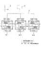
まず図1を参照して電子部品実装システム1の構成を説明する。電子部品実装システム1は、複数の電子部品実装用装置である電子部品搭載装置M1,M2,M3を直列に配置して構成されており、各電子部品搭載装置M1,M2,M3はLANシステム2を介して接続されたホストコンピュータ3によって制御される。上流側装置より供給される基板は電子部品搭載装置M1、M2,M3を順次搬送され、各電子部品搭載装置にてこれらの装置の本来機能である部品搭載作業が、これらの基板を対象として実行される。 First, the configuration of the electronic
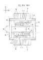
次に図2を参照して、電子部品搭載装置M1,M2,M3の構造を説明する。なお電子部品搭載装置M1,M2,M3は同一構造であり、図2では電子部品搭載装置M1のみ図示している。図2において基台4上にはX方向(基板搬送方向)に搬送路5が配設されている。搬送路5は実装対象の基板6を搬送し、部品実装ステージに位置決めする。搬送路5の両側には部品供給部7が配置されており、部品供給部7には複数のテープフィーダ8が並設されている。 Next, the structure of the electronic component mounting apparatuses M1, M2, and M3 will be described with reference to FIG. The electronic component mounting apparatuses M1, M2, and M3 have the same structure, and only the electronic component mounting apparatus M1 is shown in FIG. In FIG. 2, a
基台4のX方向の両端部にはY軸テーブル9がY方向に配設されており、Y軸テーブル9にはX軸テーブル10がX方向に架設されている。X軸テーブル10には搭載ヘッド11および搭載ヘッド11と一体的に移動する基板認識カメラ12が装着されており、Y軸テーブル9、X軸テーブル10を駆動することにより、搭載ヘッド11、基板認識カメラ12はX方向、Y方向に移動する。これにより、搭載ヘッド11は部品供給部7から電子部品を取り出して搬送路5の部品実装ステージに位置決めされた基板6に移送搭載する。また基板認識カメラ12は基板6上に移動して基板6を撮像し位置を認識する。 A Y-axis table 9 is disposed in the Y direction at both ends of the
搬送路5と部品供給部7との間には、部品認識カメラ13およびノズルストッカ14が配置されている。搬送路5から電子部品を取り出した搭載ヘッド11が部品認識カメラ13の上方を移動することにより、部品認識カメラ13は搭載ヘッド11に保持された電子部品を撮像し、これにより電子部品の位置が認識される。ノズルストッカ14は搭載ヘッド11に装着される吸着ノズルを複数種類保持する。搭載ヘッド11がノズルストッカ14にアクセスしてノズル交換動作を行うことにより、搭載ヘッド11には電子部品の種類
に応じた吸着ノズルが装着される。A component recognition camera 13 and a
次に図3を参照して、電子部品実装システム1の制御系の構成を説明する。ホストコンピュータ3は、記憶部31、制御処理部32および通信部33を備えている。記憶部31は電子部品実装システム1の全体動作を制御するのに必要な各種のデータやプログラムを記憶する。記憶部31に記憶されるプログラムには、電子部品搭載装置M1,M2,M3に本来機能を実行させるための制御プログラムが含まれる。制御処理部32は、記憶部31に記憶されたプログラムやデータに基づいて、通信部33およびLANシステム2を介して電子部品実装システム1の各電子部品搭載装置M1,M2,M3へ制御指令を送信する。この制御指令には、電子部品搭載装置M1,M2,M3において既存の制御プログラムを新たなバージョンに変更するバージョンアップ指令(図4(c)参照)が含まれる。 Next, the configuration of the control system of the electronic
電子部品搭載装置M1,M2,M3は、制御機能として機構駆動部20、操作入力部21、表示部22、記憶部23、制御部24および通信部25を備えている。なお図3においては、電子部品搭載装置M2,M3については通信部25のみ図示してその他の要素の図示は省略している。機構駆動部20は、搬送路5の基板搬送機構や部品供給部7、搭載ヘッド11によって電子部品を移送搭載するための部品搭載機構を駆動する。操作入力部21はキーボードやタッチパネルなどの入力装置であり、操作コマンドや制御データの入力を行う。表示部22は液晶パネルなどの表示装置であり、操作入力時の案内画面の表示などの各種の表示を行う。 The electronic component mounting apparatuses M1, M2, and M3 include a
記憶部23は当該電子部品搭載装置の動作や各種の処理に用いられる制御プログラムやデータを記憶する機能を有しており、システム領域A23a、システム領域B23b、バージョン記憶部23cを備えている。システム領域A23a、システム領域B23bは、各種の制御プログラムを記憶するための記憶領域のうち、当該電子部品搭載装置の本来機能である部品搭載作業を実行させるための制御プログラムを記憶する記憶領域である。すなわち本実施の形態に示す電子部品搭載装置においては、電子部品搭載装置M1,M2,M3の本来機能を実行させるための制御プログラムを記憶する記憶領域を複数備えた形態となっている。 The
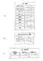
バージョン記憶部23cは、各電子部品搭載装置M1,M2,M3における各種の制御プログラムのバージョンに関する情報、すなわち図4(a)に示すような各制御プログラムごとの現行バージョン種別を示すバージョン情報および図4(b)に示すように各制御プログラムごとのバージョン変更の履歴情報を記憶する。 The
図4(a)に示すように、各種の制御プログラム(本体システム、HMI(ヒューマンマシンインターフェイス)、認識、搬送、ヘッド、供給など)のうち、本体システム、HMIおよび認識など、当該装置の本来機能に関する制御プログラムについては、それぞれA,B2種類のバージョンが記憶されている。そして図4(b)に示すように、バージョン変更の履歴情報では、その時点までに行われたバージョン変更の日付けおよび変更後のバージョン種別が記憶されている。ここでは、システム領域B23bに記憶される制御プログラム(本体システム)のバージョン履歴が示されている。 As shown in FIG. 4A, among the various control programs (main system, HMI (human machine interface), recognition, transport, head, supply, etc.), the main functions of the device such as the main system, HMI and recognition As for the control program, two types of versions A and B are stored. As shown in FIG. 4B, the version change history information stores the date of the version change made up to that point and the version type after the change. Here, the version history of the control program (main system) stored in the system area B23b is shown.
制御部24は、ホストコンピュータ3からの制御指令に従い、記憶部23に記憶された制御プログラムに基づいて当該装置内の各部の動作や処理を制御する機能を有しており、実行処理部24a、領域切替部24bを備えている。実行処理部24aは、記憶部23の複数の記憶領域(システム領域A23a、システム領域B23b)を対象として、制御プログラムを書き込む書込処理、書き込まれた制御プログラムを読み出す読出処理、読み出した制御プログラムにより当該電子部品搭載装置の各部を制御する機能を有している。このとき記憶部23には複数の記憶領域が独立して設けられていることから、実行処理部2
4aはこれらの記憶領域を対象とした処理を同時並行的に実行することができるようになっている。すなわち実行処理部24aは、一の記憶領域を対象として読出処理を実行して電子部品実装用装置に本来機能を実行させている間に、他の記憶領域を対象として新たな制御プログラムの書込処理を実行する。The
The process 4a can simultaneously execute processes for these storage areas. In other words, the execution processing unit 24a executes a reading process on one storage area and causes the electronic component mounting apparatus to execute the original function while writing a new control program on another storage area. Execute the process.
領域切替部24bは、上述の実行処理部24aによる書込処理、読出処理において、対象となるシステム領域を切り替える処理を、ホストコンピュータ3からの制御プログラム更新指令(バージョン変更指令)に基づいて行う。図4(c)は、このバージョン変更指令の例を示している。すなわち領域切替部24bは、記憶部23へ制御プログラムを書き込む書込処理および書き込まれた制御プログラムを読み出す読出処理において、書込処理または読出処理の対象となる記憶領域を切り替える。 The
通信部25は、LANシステム2を介してホストコンピュータ3の通信部33と接続されており、当該装置の制御に必要な信号の授受を上位制御装置であるホストコンピュータ3との間で行うことができるようになっている。前述の記憶領域の切替において、領域切替部24bは上位制御装置であるホストコンピュータ3より通信部25を介して送信される制御プログラムの更新指令に基づいて、対象となる記憶領域を切り替える処理を行う。そして更新処理が実行された後には、通信部25は制御プログラムの更新結果をホストコンピュータ3に送信する。 The
次に図5を参照して、電子部品実装システム1における制御プログラムの更新処理について説明する。この更新処理は、制御プログラムのデバッグや機能改善などを目的とするバージョンアップが実行された場合に、電子部品実装システム1を構成する各電子部品搭載装置M1,M2,M3において当該装置の記憶部23に新たな制御プロフラムをインストールするものである。 Next, a control program update process in the electronic
まず、ホストコンピュータ3からプログラム更新指令が更新処理の対象となる電子部品搭載装置に対して送信され(ST1)、これ以降の処理は各装置にて自動的に実行される。プログラム更新指令は、図4(c)に示すようなバージョン変更指示の形で行われ、現行バージョン種別と変更後バージョン種別を指示することにより行われる。プログラム更新指令を受けた電子部品搭載装置では、当該更新指令の対象となる制御プログラムのバージョンの一致を確認する(ST2)。すなわち、バージョン記憶部23cに記憶されているバージョン情報(図4(a)参照)を参照して、既インストールの制御プログラムの現行バージョンを確認する。 First, a program update command is transmitted from the
ここで現行バージョンが、指示された変更後バージョンと一致している場合には、バージョン変更処理を実行する必要がないと判断して、そのまま生産を継続する(ST3)。そして(ST2)にてバージョンが一致していない場合には、記憶部23の2つの記憶領域のうち、待機中のシステム領域、すなわち当該時点において制御プログラムの読み込み対象となっていないシステム領域に、更新される新たなバージョンの制御プログラムをインストールする(ST4)。新たなバージョンの制御プログラムは、プログラム更新指令とともにホストコンピュータ3から各装置に送信され、通信部25を介して受信される。 If the current version matches the instructed version after change, it is determined that there is no need to execute the version change process, and production is continued as it is (ST3). If the versions do not match in (ST2), the standby system area of the two storage areas of the
このバージョンアップのためのプログラム変更処理が実行される間には、当該電子部品搭載装置の表示部22には「インストール中」が表示される(ST5)。これにより、プログラム変更処理実行中に不注意によりマシンオペレータが電源をオフするなど不適切なマシン操作を行うことが防止される。インストールが終了するとバージョン記憶部23cのバージョン履歴を更新する(ST6)。次いで当該装置への新たな基板搬入が停止され(ST7)、既に搬入済みの基板を対象として部品搭載動作などの生産作業が継続実行される。そして搬入済みの基板への部品搭載作業が完了するEOP(エンド・オブ・プログ
ラム)で当該基板が搬出された後、設備停止する(ST8)。While the program change process for upgrading is being executed, “installing” is displayed on the
この後、当該装置内に未搬出の基板が残留していないことが装置の基板検出機能によって確認された後、読込処理の対象となる記憶領域の切り替えが領域切替部24bによって実行される(ST9)。ここでは更新された新たなバージョンの制御プログラムがインストールされたシステム領域が、新たに読込処理の対象となるシステム領域として設定され、実行処理部24aはこの新たなシステム領域を対象として読込処理を実行する。 Thereafter, after it is confirmed by the board detection function of the apparatus that no uncarried board remains in the apparatus, the
この後、制御プログラムの更新が正常に行われて、読込処理の対象となるシステム領域が切り替えられた旨がホストコンピュータ3に通知され(ST10)、設備再起動(ST11)の後、当該装置による生産が再開される(ST12)。制御プログラムの切替に際し、このようなプロセスに従うことにより、各基板にどのバージョンの制御プログラムが適用されたかを各基板ごとに生産履歴として記録することができ、生産管理におけるトレーサビリティの確保が担保される。 Thereafter, the update of the control program is normally performed, the
すなわち上述の電子部品実装用装置における制御プログラムの更新処理においては、一のシステム領域を対象として制御プログラムの読出処理を実行して電子部品実装用装置としての電子部品搭載装置M1,M2,M3に本来機能を実行させている間に、他のシステム領域を対象として新たな制御プログラムの書込処理を同時並行的に実行するようにしている。そして当該装置の通信部25は、制御プログラムの更新結果を上位制御装置であるホストコンピュータ3に送信するようにしている。 That is, in the above-described control program update process in the electronic component mounting apparatus, the control program read process is executed for one system area, and the electronic component mounting apparatuses M1, M2, and M3 as the electronic component mounting apparatuses are executed. While the original function is being executed, the writing process of a new control program is executed simultaneously in parallel for other system areas. And the
なお図5に示す処理フローにおいては、新たなバージョンに更新された後の設備再起動時に、新たなバージョンの制御プログラムがインストールされたシステム領域が、新たに読出対象のシステム領域として自動的に設定される例を示しているが、旧バージョンの制御プログラムがインストールされたシステム領域が、引き続き読出対象のシステム領域として自動的に設定されるようにしてもよい。この場合には、上述の更新処理を実行した後の任意のタイミングにて、ホストコンピュータ3からの指令により読出対象となるシステム領域の切替が実行される。 In the processing flow shown in FIG. 5, when the equipment is restarted after being updated to a new version, the system area in which the new version of the control program is installed is automatically set as a new system area to be read. However, the system area in which the old version of the control program is installed may be automatically set as the system area to be read continuously. In this case, switching of the system area to be read is executed by an instruction from the
次に図6を参照して、電子部品実装システム1における制御プログラムの切替処理について説明する。この切替処理は、上述の更新処理が実行されて新バージョンに更新された後に、新バージョンの制御プログラムに不具合が発見された場合など、旧バージョンに復帰するバージョンダウンを実行する必要がある場合の処理を示している。 Next, a control program switching process in the electronic
まず、ホストコンピュータ3からプログラム切替指令が更新処理の対象となる電子部品搭載装置に対して送信される(ST21)。そしてプログラム切替指令を受けた電子部品搭載装置では、当該切替指令の対象となる制御プログラムのバージョンの一致を確認する(ST22)。すなわち、当該時点において実行処理部24aの読出処理の対象となっているシステム領域にインストールされている制御プログラムのバージョンを、バージョン記憶部23cに記憶されているバージョン情報(図4(a)参照)を参照して確認する。 First, a program switching command is transmitted from the
ここで確認されたバージョンが、バージョンダウンの対象として指示された旧バージョンと一致している場合には、切替処理を実行する必要がないと判断して、そのまま生産を継続する(ST23)。そして(ST22)にてバージョンが一致していない場合には、当該装置への新たな基板搬入が停止され(ST24)、既に搬入済みの基板を対象として部品搭載動作などの生産作業が継続実行される。そして搬入済みの基板への部品搭載作業が完了するEOP(エンド・オブ・プログラム)で当該基板が搬出された後、設備停止する(ST25)。 If the confirmed version matches the old version instructed to be downgraded, it is determined that there is no need to execute the switching process, and production is continued as it is (ST23). If the versions do not match in (ST22), the new board loading to the apparatus is stopped (ST24), and the production work such as the component mounting operation is continuously executed for the board already loaded. The Then, after the board is unloaded by EOP (end of program), which completes the component mounting work on the loaded board, the equipment is stopped (ST25).
この後、領域切り替えが領域切替部24bによって実行される(ST26)。すなわち更新される前の旧バージョンの制御プログラムがインストールされたシステム領域が、再度読出処理の対象となるシステム領域として設定され、実行処理部24aはこのシステム領域から制御プラグラムを読み出す。この後、制御プログラムの切替が行われてシステム領域が切り替えられた旨がホストコンピュータ3に通知され(ST27)、設備再起動(ST28)の後、当該装置による生産が再開される(ST29)。ここでは、(ST28)における設備再起動は自動で行うようにしてもよく、また表示部22に表示された再起動を促すメッセージに応じて、マシンオペレータが手動で行うようにしてもよい。 Thereafter, region switching is executed by the
上記説明したように、本発明においては、電子部品実装システムを構成する各電子部品実装用装置に、制御プログラムを記憶する記憶領域を複数備えた記憶部と、この記憶部へ前記制御プログラムを書き込む書込処理および書き込まれた制御プログラムを読み出す読出処理において書込処理または読出処理の対象となる前記記憶領域を切り替える領域切替部とを備えるようにしている。これにより、一の記憶領域を対象として読出処理を実行して電子部品実装用装置に本来機能を実行させている間に、他の記憶領域を対象として新たな制御プログラムの書込処理を同時並行的に実行することが可能となる。 As described above, in the present invention, each electronic component mounting apparatus constituting the electronic component mounting system has a storage unit having a plurality of storage areas for storing control programs, and writes the control program to the storage unit. An area switching unit that switches the storage area that is the target of the writing process or the reading process in the writing process and the reading process of reading the written control program is provided. As a result, while executing the reading process for one storage area and causing the electronic component mounting apparatus to execute the original function, the writing process of a new control program for the other storage area is simultaneously performed in parallel. Can be executed automatically.
したがって、バージョンアップのための新たな制御プログラムのインストール処理中においても設備稼働を停止する必要が無く、特に本実施の形態に示すように複数の装置を連結して構成された電子部品実装システムにおいて、制御プログラムのバージョンアップのためのライン停止に起因する時間損失を解消して、生産性を向上させることができる。 Therefore, it is not necessary to stop the operation of the equipment even during the installation process of a new control program for version upgrade, and particularly in an electronic component mounting system configured by connecting a plurality of devices as shown in the present embodiment. It is possible to eliminate the time loss caused by the line stop for the upgrade of the control program and improve the productivity.
なお本実施の形態においては、電子部品実装システムを構成する電子部品実装用装置として、基板に電子部品を移送搭載する部品搭載作業を本来機能とする電子部品搭載装置の例を示したが、本発明の適用はこれに限定されず、スクリーン印刷装置、印刷後の検査を行う印刷検査装置、部品搭載後の検査を行う外観検査装置などに対しても本発明を適用することができる。スクリーン印刷装置の場合には、スクリーン印刷作業が本来機能であり、印刷検査装置、外観検査装置では基板を対象とした撮像および認識が本来機能となる。 In the present embodiment, an example of an electronic component mounting device that originally functions as a component mounting operation for transferring and mounting an electronic component on a board has been shown as an electronic component mounting device constituting the electronic component mounting system. The application of the invention is not limited to this, and the present invention can also be applied to a screen printing apparatus, a printing inspection apparatus that performs inspection after printing, an appearance inspection apparatus that performs inspection after mounting components, and the like. In the case of a screen printing apparatus, screen printing work is an original function, and in a print inspection apparatus and an appearance inspection apparatus, imaging and recognition for a substrate are an original function.
本発明の電子部品実装用装置および電子部品実装用装置における制御プログラムの更新方法は、制御プログラムのバージョンアップのためのライン停止に起因する時間損失を解消して生産性を向上させることができるという効果を有し、電子部品を基板に実装する電子部品実装分野において有用である。 The electronic component mounting apparatus and the method for updating a control program in the electronic component mounting apparatus according to the present invention can improve productivity by eliminating time loss caused by line stop for upgrading the control program. It has an effect and is useful in the field of electronic component mounting where electronic components are mounted on a substrate.
1 電子部品実装システム
3 ホストコンピュータ(上位制御装置)
23a システム領域A(記憶領域)
23b システム領域B(記憶領域)
M1,M2,M3 電子部品搭載装置1 Electronic
23a System area A (storage area)
23b System area B (storage area)
M1, M2, M3 Electronic component mounting device
Claims (2)
Translated fromJapanese当該電子部品実装用装置に電子部品実装用の本来機能を実行させるための制御プログラムを記憶する記憶領域を複数備えた記憶部と、前記記憶部へ前記制御プログラムを書き込む書込処理および書き込まれた制御プログラムを読み出す読出処理において前記書込処理または読出処理の対象となる前記記憶領域を切り替える領域切替部と、一の前記記憶領域を対象として前記読出処理を実行して前記電子部品実装用装置に本来機能を実行させている間に他の記憶領域を対象として新たな制御プログラムの書込処理を実行する実行処理部と、上位制御装置との間でデータの授受を行う通信部とを備え、
前記領域切替部は前記上位制御装置より前記通信部を介して送信される制御プログラムの更新指令に基づいて前記対象となる記憶領域を切り替え、前記通信部は前記制御プログラムの更新結果を前記上位制御装置に送信することを特徴とする電子部品実装用装置。An electronic component mounting apparatus constituting an electronic component mounting system for mounting electronic components on a substrate,
A storage unit for the control program with a plurality of storage areas for storing for executing the inherent function of the electronic component mounted on the electronic component mounting apparatus, the writing processand specification for writing the control program into the storage unit An area switching unit that switches the storage area to be the target of the writing process or the reading process in a reading process of reading the control program that is inserted; and the electronic component that executes the reading process for one of the storage areas An execution processing unit that executes writing processing of a new control program for another storage area while the mounting device is executing the original function,and a communication unit that transfers data between the host control device And
The region switching unit switches the target storage region based on a control program update command transmitted from the host control device via the communication unit, and the communication unit transmits the control program update result to the host control. An electronic component mounting apparatus, characterizedby beingtransmitted to the apparatus.
一の前記記憶領域を対象として前記読出処理を実行して前記電子部品実装用装置に本来機能を実行させている間に他の記憶領域を対象として新たな制御プログラムの書込処理を実行し、前記領域切換部は前記上位制御装置より前記通信部を介して送信される制御プログラムの更新指令に基づいて前記対象となる記憶領域を切り替え、前記通信部は前記制御プログラムの更新結果を前記上位制御装置に送信することを特徴とする電子部品実装用装置における制御プログラムの更新方法。An electronic component mounting apparatus constituting an electronic component mounting system for mounting an electronic component on a board, and a storage area for storing a control program for causing the electronic component mounting apparatus to execute an original function for mounting the electronic component switching a storage unit having a plurality, said storage area to be the write process or read process in the reading process of reading a control program incorporated can write processingand manual writing the control program into the storage unit and area switchingunit, in the electronic component mounting apparatus that includesa communication unit for exchanging data with a hostcontroller, a method of updating the control program in the electronic component mounting apparatus to update the control program,
While executing the reading process for one of the storage areas and causing the electronic component mounting apparatus to execute the original function, write a new control program for the other storage area, The region switching unit switches the target storage region based on a control program update command transmitted from the host control device via the communication unit, and the communication unit transmits the control program update result to the host control. A method of updating a control program in an electronic component mountingapparatus, comprising: transmitting to the apparatus.
Priority Applications (1)
| Application Number | Priority Date | Filing Date | Title |
|---|---|---|---|
| JP2007037571AJP4743133B2 (en) | 2007-02-19 | 2007-02-19 | Electronic component mounting apparatus and control program update method in electronic component mounting apparatus |
Applications Claiming Priority (1)
| Application Number | Priority Date | Filing Date | Title |
|---|---|---|---|
| JP2007037571AJP4743133B2 (en) | 2007-02-19 | 2007-02-19 | Electronic component mounting apparatus and control program update method in electronic component mounting apparatus |
Publications (2)
| Publication Number | Publication Date |
|---|---|
| JP2008205075A JP2008205075A (en) | 2008-09-04 |
| JP4743133B2true JP4743133B2 (en) | 2011-08-10 |
Family
ID=39782295
Family Applications (1)
| Application Number | Title | Priority Date | Filing Date |
|---|---|---|---|
| JP2007037571AExpired - Fee RelatedJP4743133B2 (en) | 2007-02-19 | 2007-02-19 | Electronic component mounting apparatus and control program update method in electronic component mounting apparatus |
Country Status (1)
| Country | Link |
|---|---|
| JP (1) | JP4743133B2 (en) |
Cited By (1)
| Publication number | Priority date | Publication date | Assignee | Title |
|---|---|---|---|---|
| CN111886940A (en)* | 2018-03-29 | 2020-11-03 | 株式会社富士 | Management device for substrate working machine |
Families Citing this family (10)
| Publication number | Priority date | Publication date | Assignee | Title |
|---|---|---|---|---|
| JP5190796B2 (en) | 2008-11-11 | 2013-04-24 | 横河電機株式会社 | Field device and field device software update system using the same |
| US8914783B2 (en) | 2008-11-25 | 2014-12-16 | Fisher-Rosemount Systems, Inc. | Software deployment manager integration within a process control system |
| US8898660B2 (en) | 2008-11-25 | 2014-11-25 | Fisher-Rosemount Systems, Inc. | Systems and methods to provide customized release notes during a software system upgrade of a process control system |
| JP5529670B2 (en)* | 2010-07-30 | 2014-06-25 | 株式会社日立ハイテクインスツルメンツ | Electronic component mounting line management system |
| JP5729941B2 (en)* | 2010-08-18 | 2015-06-03 | 富士機械製造株式会社 | Mounting control data editing apparatus and editing method in component mounting apparatus |
| JP5545759B2 (en)* | 2011-01-18 | 2014-07-09 | 富士通テレコムネットワークス株式会社 | Function addition type control device and function addition type control system |
| JP2012230988A (en)* | 2011-04-26 | 2012-11-22 | Panasonic Corp | Component mounting system and supporting method for operator in component mounting system |
| JP5623331B2 (en)* | 2011-04-26 | 2014-11-12 | パナソニック株式会社 | Component mounting system and operator support method in component mounting system |
| CN106462477B (en)* | 2014-07-31 | 2022-05-31 | 三菱电机株式会社 | Device management device and management program update method |
| JP6492292B2 (en)* | 2016-09-28 | 2019-04-03 | パナソニックIpマネジメント株式会社 | How to upgrade programs on a component mounting line |
Family Cites Families (2)
| Publication number | Priority date | Publication date | Assignee | Title |
|---|---|---|---|---|
| JPH09260898A (en)* | 1996-03-27 | 1997-10-03 | Matsushita Electric Ind Co Ltd | Electronic component mounting method and device |
| JP2002044238A (en)* | 2000-07-27 | 2002-02-08 | Nec Eng Ltd | Private branch exchange |
- 2007
- 2007-02-19JPJP2007037571Apatent/JP4743133B2/ennot_activeExpired - Fee Related
Cited By (1)
| Publication number | Priority date | Publication date | Assignee | Title |
|---|---|---|---|---|
| CN111886940A (en)* | 2018-03-29 | 2020-11-03 | 株式会社富士 | Management device for substrate working machine |
Also Published As
| Publication number | Publication date |
|---|---|
| JP2008205075A (en) | 2008-09-04 |
Similar Documents
| Publication | Publication Date | Title |
|---|---|---|
| JP4743133B2 (en) | Electronic component mounting apparatus and control program update method in electronic component mounting apparatus | |
| JP4847956B2 (en) | Electronic component mounting system and electronic component mounting method | |
| CN107872948B (en) | Version upgrading method for program in component mounting production line | |
| JP2009094437A (en) | Electronic component mounting apparatus and control program update method | |
| JP2009094270A (en) | Electronic component mounting system and operation instruction method in electronic component mounting system | |
| EP3043629B1 (en) | Data processing device to be used by substrate working machine, and substrate working system having same | |
| JP5165507B2 (en) | Component mounting method | |
| JP4100240B2 (en) | Electronic component mounting system and electronic component mounting method | |
| JP2008227094A (en) | Component mounting method and component mounting system | |
| JP7029569B2 (en) | Software update method and management device for board work equipment | |
| JP2014241373A (en) | Substrate work machine | |
| JP2014241328A (en) | Electronic component mounting machine | |
| JP7137379B2 (en) | Production system, management device, program | |
| JP4356796B2 (en) | Electronic component mounting method | |
| JP4952476B2 (en) | Electronic component mounting system | |
| JP2006313806A (en) | Electronic component mounting apparatus and power supply control method in electronic component mounting apparatus | |
| JP7217348B2 (en) | Management device and management system for working machine for board | |
| JP4515350B2 (en) | Electronic component mounting method | |
| JP5623331B2 (en) | Component mounting system and operator support method in component mounting system | |
| JP2024116753A (en) | Component mounting system, component mounting device, production data transmission method, and production data reception method | |
| WO2021009984A1 (en) | Component mounting device | |
| JP2006261601A (en) | Processing execution method in component mounting system and component mounting system | |
| JP2015194825A (en) | Image forming apparatus | |
| JP2005231054A (en) | Image forming apparatus, and method for downloading software |
Legal Events
| Date | Code | Title | Description |
|---|---|---|---|
| A621 | Written request for application examination | Free format text:JAPANESE INTERMEDIATE CODE: A621 Effective date:20090202 | |
| RD01 | Notification of change of attorney | Free format text:JAPANESE INTERMEDIATE CODE: A7421 Effective date:20091127 | |
| A977 | Report on retrieval | Free format text:JAPANESE INTERMEDIATE CODE: A971007 Effective date:20110124 | |
| A131 | Notification of reasons for refusal | Free format text:JAPANESE INTERMEDIATE CODE: A131 Effective date:20110201 | |
| A521 | Request for written amendment filed | Free format text:JAPANESE INTERMEDIATE CODE: A523 Effective date:20110322 | |
| A01 | Written decision to grant a patent or to grant a registration (utility model) | Free format text:JAPANESE INTERMEDIATE CODE: A01 Effective date:20110412 | |
| A61 | First payment of annual fees (during grant procedure) | Free format text:JAPANESE INTERMEDIATE CODE: A61 Effective date:20110425 | |
| FPAY | Renewal fee payment (event date is renewal date of database) | Free format text:PAYMENT UNTIL: 20140520 Year of fee payment:3 | |
| FPAY | Renewal fee payment (event date is renewal date of database) | Free format text:PAYMENT UNTIL: 20140520 Year of fee payment:3 | |
| S111 | Request for change of ownership or part of ownership | Free format text:JAPANESE INTERMEDIATE CODE: R313113 | |
| R350 | Written notification of registration of transfer | Free format text:JAPANESE INTERMEDIATE CODE: R350 | |
| LAPS | Cancellation because of no payment of annual fees |