JP4740127B2 - Base unit for dual wiring system - Google Patents
Base unit for dual wiring systemDownload PDFInfo
- Publication number
- JP4740127B2 JP4740127B2JP2006515421AJP2006515421AJP4740127B2JP 4740127 B2JP4740127 B2JP 4740127B2JP 2006515421 AJP2006515421 AJP 2006515421AJP 2006515421 AJP2006515421 AJP 2006515421AJP 4740127 B2JP4740127 B2JP 4740127B2
- Authority
- JP
- Japan
- Prior art keywords
- base unit
- unit
- functional unit
- functional
- power
- Prior art date
- Legal status (The legal status is an assumption and is not a legal conclusion. Google has not performed a legal analysis and makes no representation as to the accuracy of the status listed.)
- Expired - Fee Related
Links
Images


Classifications
- H—ELECTRICITY
- H01—ELECTRIC ELEMENTS
- H01R—ELECTRICALLY-CONDUCTIVE CONNECTIONS; STRUCTURAL ASSOCIATIONS OF A PLURALITY OF MUTUALLY-INSULATED ELECTRICAL CONNECTING ELEMENTS; COUPLING DEVICES; CURRENT COLLECTORS
- H01R25/00—Coupling parts adapted for simultaneous co-operation with two or more identical counterparts, e.g. for distributing energy to two or more circuits
- H01R25/006—Coupling parts adapted for simultaneous co-operation with two or more identical counterparts, e.g. for distributing energy to two or more circuits the coupling part being secured to apparatus or structure, e.g. duplex wall receptacle
- H—ELECTRICITY
- H02—GENERATION; CONVERSION OR DISTRIBUTION OF ELECTRIC POWER
- H02G—INSTALLATION OF ELECTRIC CABLES OR LINES, OR OF COMBINED OPTICAL AND ELECTRIC CABLES OR LINES
- H02G3/00—Installations of electric cables or lines or protective tubing therefor in or on buildings, equivalent structures or vehicles
- H—ELECTRICITY
- H04—ELECTRIC COMMUNICATION TECHNIQUE
- H04L—TRANSMISSION OF DIGITAL INFORMATION, e.g. TELEGRAPHIC COMMUNICATION
- H04L12/00—Data switching networks
- H04L12/28—Data switching networks characterised by path configuration, e.g. LAN [Local Area Networks] or WAN [Wide Area Networks]
- H04L12/40—Bus networks
- H—ELECTRICITY
- H01—ELECTRIC ELEMENTS
- H01R—ELECTRICALLY-CONDUCTIVE CONNECTIONS; STRUCTURAL ASSOCIATIONS OF A PLURALITY OF MUTUALLY-INSULATED ELECTRICAL CONNECTING ELEMENTS; COUPLING DEVICES; CURRENT COLLECTORS
- H01R25/00—Coupling parts adapted for simultaneous co-operation with two or more identical counterparts, e.g. for distributing energy to two or more circuits
- H01R25/16—Rails or bus-bars provided with a plurality of discrete connecting locations for counterparts
- H01R25/164—Connecting locations formed by flush mounted apparatus
- H—ELECTRICITY
- H04—ELECTRIC COMMUNICATION TECHNIQUE
- H04L—TRANSMISSION OF DIGITAL INFORMATION, e.g. TELEGRAPHIC COMMUNICATION
- H04L12/00—Data switching networks
- H04L12/28—Data switching networks characterised by path configuration, e.g. LAN [Local Area Networks] or WAN [Wide Area Networks]
- H04L12/2803—Home automation networks
- Y—GENERAL TAGGING OF NEW TECHNOLOGICAL DEVELOPMENTS; GENERAL TAGGING OF CROSS-SECTIONAL TECHNOLOGIES SPANNING OVER SEVERAL SECTIONS OF THE IPC; TECHNICAL SUBJECTS COVERED BY FORMER USPC CROSS-REFERENCE ART COLLECTIONS [XRACs] AND DIGESTS
- Y02—TECHNOLOGIES OR APPLICATIONS FOR MITIGATION OR ADAPTATION AGAINST CLIMATE CHANGE
- Y02B—CLIMATE CHANGE MITIGATION TECHNOLOGIES RELATED TO BUILDINGS, e.g. HOUSING, HOUSE APPLIANCES OR RELATED END-USER APPLICATIONS
- Y02B70/00—Technologies for an efficient end-user side electric power management and consumption
- Y02B70/30—Systems integrating technologies related to power network operation and communication or information technologies for improving the carbon footprint of the management of residential or tertiary loads, i.e. smart grids as climate change mitigation technology in the buildings sector, including also the last stages of power distribution and the control, monitoring or operating management systems at local level
- Y—GENERAL TAGGING OF NEW TECHNOLOGICAL DEVELOPMENTS; GENERAL TAGGING OF CROSS-SECTIONAL TECHNOLOGIES SPANNING OVER SEVERAL SECTIONS OF THE IPC; TECHNICAL SUBJECTS COVERED BY FORMER USPC CROSS-REFERENCE ART COLLECTIONS [XRACs] AND DIGESTS
- Y04—INFORMATION OR COMMUNICATION TECHNOLOGIES HAVING AN IMPACT ON OTHER TECHNOLOGY AREAS
- Y04S—SYSTEMS INTEGRATING TECHNOLOGIES RELATED TO POWER NETWORK OPERATION, COMMUNICATION OR INFORMATION TECHNOLOGIES FOR IMPROVING THE ELECTRICAL POWER GENERATION, TRANSMISSION, DISTRIBUTION, MANAGEMENT OR USAGE, i.e. SMART GRIDS
- Y04S20/00—Management or operation of end-user stationary applications or the last stages of power distribution; Controlling, monitoring or operating thereof
- Y04S20/20—End-user application control systems
Landscapes
- Engineering & Computer Science (AREA)
- Architecture (AREA)
- Civil Engineering (AREA)
- Structural Engineering (AREA)
- Computer Networks & Wireless Communication (AREA)
- Signal Processing (AREA)
- Details Of Indoor Wiring (AREA)
- Selective Calling Equipment (AREA)
- Casings For Electric Apparatus (AREA)
- Connector Housings Or Holding Contact Members (AREA)
- Installation Of Indoor Wiring (AREA)
- Interconnected Communication Systems, Intercoms, And Interphones (AREA)
Description
Translated fromJapanese本発明は、構造物に配設された電力線と信号線を介して、電力の供給および情報の入出力に使用されるデュアル配線システムに関するものである。 The present invention relates to a dual wiring system used for power supply and information input / output via a power line and a signal line arranged in a structure.
インターネットの普及により、一般住宅やオフィスビルディングのような建造物内の多くの場所で情報ネットワークへのアクセス性の確保が望まれている。例えば、日本公開特許公報11−187154号は、建造物に配設される電力供給線および種々の信号線を集中して管理するための配線盤と、室内の壁面に埋設され、電力供給線と信号線を介して前記配線盤に接続されるマルチメディアコンセントパネルとを有するマルチメディア配線システムについて記載している。例えば、マルチメディアコンセントパネルは、商用電源を電気機器に供給するための電源コンセント、地上波放送、衛星放送、ケーブル放送のような放送番組受信用コンセント、インターネットや電話に使用されるアナログおよびデジタル回線用モジュラージャック等を有する。このマルチメディア配線システムの使用によりマルチメディア製品の利便性が向上し、情報化社会において快適な生活/作業環境が得られる。 Due to the spread of the Internet, it is desired to ensure accessibility to information networks in many places in buildings such as ordinary houses and office buildings. For example, Japanese Patent Application Publication No. 11-187154 discloses a power board and a wiring board for centrally managing various power supply lines and various signal lines arranged in a building; A multimedia wiring system having a multimedia outlet panel connected to the wiring board via a signal line is described. For example, multimedia outlet panels are power outlets for supplying commercial power to electrical equipment, outlets for receiving broadcast programs such as terrestrial broadcasting, satellite broadcasting, and cable broadcasting, and analog and digital lines used for the Internet and telephones. For example, it has a modular jack. Use of this multimedia wiring system improves the convenience of multimedia products and provides a comfortable living / working environment in the information society.
ところで、上記したマルチメディアコンセントパネルは、通常、建造物の建設工事中に壁面に組み込まれ、情報線や電力線に接続される。これは、マルチメディアコンセントパネルの機能が、建設工事の際に決定されることを意味する。したがって、工事終了後にマルチメディアコンセントパネルに新しい機能を追加したり、既存のマルチメディアコンセントパネルの一部の機能を別の機能と交換することは難しい。また、既存のマルチメディアコンセントパネルを別のマルチメディアパネルに交換する場合は、補修工事が必要になるが、そのような補修工事の実施は一般の使用者にとって容易でなく、また補修工事の費用は使用者にとって負担となる。 By the way, the above-described multimedia outlet panel is usually incorporated into a wall surface during construction of a building and connected to an information line or a power line. This means that the function of the multimedia outlet panel is determined during construction. Therefore, it is difficult to add a new function to the multimedia outlet panel after the construction is completed or to replace a part of the existing multimedia outlet panel with another function. In addition, when an existing multimedia outlet panel is replaced with another multimedia panel, repair work is required. However, such repair work is not easy for general users and the cost of the repair work is also low. Is a burden on the user.
このように、従来のマルチメディアコンセントパネルは、機能拡張性および交換容易性の観点から依然として改善の余地がある。 Thus, the conventional multimedia outlet panel still has room for improvement from the viewpoint of function expandability and exchangeability.
したがって、本発明の目的は、改善された機能拡張性および交換容易性を有するデュアル配線システムに適したベースユニットを提供することにある。 Accordingly, it is an object of the present invention to provide a base unit suitable for a dual wiring system having improved function expandability and exchangeability.
すなわち、本発明のデュアル配線システム用ベースユニットは、建造物の壁面に埋め込まれ、建造物内に配設された電力線と情報線の両方に接続して使用され、固有に種々の機能部を有する複数種類の機能ユニットの何れかが接続される。このベースユニットは、複数種類の機能ユニットの間で共用されるように定型化されたモジュールポートとモジュールコネクタの一方を有し、機能ユニットに設けたモジュールポートとモジュールコネクタの他方と着脱可能に接続されて、ベースユニットから機能ユニットへの給電と、ベースユニットと機能ユニットとの間での信号伝送の両方を同時に確立し、それにより機能ユニットに、電力線からの電力の供給、情報線からの情報の出力、および情報線への情報の入力の少なくとも一つの機能を提供する。さらに、ベースユニットは、電力線と情報線に接続される端子を設けた背面部と、電気機器のコンセントが挿入される電源コンセントおよび電気機器をON/OFFするためのスイッチの少なくとも一つを有する正面部と、上記機能ユニットが壁面に沿う方向にベースユニットに着脱可能に接続されるように上記モジュールコネクタおよびモジュールポートの一方を有する側面部とを含むハウジングを有するとともに、機能ユニットは、ベースユニットの側面部と対向する側面に、上記モジュールコネクタおよびモジュールポートの他方を有することを特徴とする。That is, the dual wiring system base unit of the present invention is embedded in the wall surface of the building, is used by being connected to both the power line and the information line arranged in the building, and has various functional parts inherently. One of a plurality of types of functional units is connected. This base unit has one of a module port and a module connector that are standardized so that they can be shared among multiple types of functional units, and is detachably connected to the module port provided on the functional unit and the other of the module connectors. The power supply from the base unit to the functional unit and the signal transmission between the base unit and the functional unit are established at the same time, thereby supplying the power to the functional unit from the power line and the information from the information line. And at least one function of inputting information to the information line. Further, the base unit has a rear surface portion provided with terminals connected to the power line and the information line, a front surface having at least one of a power outlet into which the outlet of the electric device is inserted and a switch for turning on / off the electric device. And a side part having one of the module connector and the module port so that the functional unit is detachably connected to the base unit in a direction along the wall surface. The other side of the module connector and the module port is provided on a side surface facing the side surface portion .
本発明によれば、ベースユニットから機能ユニットへの電力供給と、ベースユニットと機能ユニット間における情報信号の双方向コミュニケーションの両方が、モジュールポートとモジュールコネクタの接続によって同時に得ることができるので、一般のユーザーは、ベースユニットにすでに接続されている機能ユニットを別の機能ユニットに面倒な補修作業を実施することなく容易に交換することができる。また、建造物の壁面に組み込まれた複数のベースユニットの各々を、コンセント、スイッチ、コントローラ、モニタ、スピーカ等の種々の機能を有する複数の機能ユニットの間で共用できる。したがって、機能ユニットのレイアウト自由度の向上が、使用者のニーズに合った快適で便利な生活/作業環境を提供する。さらに、ベースユニットは、電力線と情報線に接続される端子を設けた背面部と、電気機器のコンセントが挿入される電源コンセントおよび電気機器をON/OFFするためのスイッチの少なくとも一つを有する正面部と、上記機能ユニットが壁面に沿う方向にベースユニットに着脱可能に接続されるように上記モジュールコネクタおよびモジュールポートを有する側面部とを含むハウジングを有しているので、室内空間の美観を損なうことなく、デュアル配線システムにおける機能拡張性を向上することができる。According to the present invention, both power supply from the base unit to the functional unit and bidirectional communication of information signals between the base unit and the functional unit can be obtained simultaneously by connecting the module port and the module connector. The user can easily replace the functional unit already connected to the base unit with another functional unit without performing troublesome repair work. Each of the plurality of base units incorporated in the wall surface of the building can be shared among a plurality of functional units having various functions such as an outlet, a switch, a controller, a monitor, and a speaker. Therefore, the improvement in the layout flexibility of the functional unit provides a comfortable and convenient living / working environment that meets the needs of the user.Further, the base unit has a rear surface portion provided with terminals connected to the power line and the information line, a front surface having at least one of a power outlet into which the outlet of the electric device is inserted and a switch for turning on / off the electric device. And the side wall having the module connector and the module port so that the functional unit is detachably connected to the base unit in the direction along the wall surface, the appearance of the indoor space is impaired. Therefore, the function expandability in the dual wiring system can be improved.
上記デュアル配線システム用ベースユニットにおいて、モジュールコネクタおよびモジュールポートは、ベースユニットから機能ユニットへの給電を行うために互いに着脱可能に接続される一対の電力ポートと電力コネクタ、およびベースユニットと機能ユニットの間での信号伝送を行うために互いに着脱可能に接続される一対の情報信号ポート及び情報信号コネクタを有することが好ましい。特に、電力コネクタと電力ポートは、ベースユニットから機能ユニットに電磁結合の手法により給電し、情報信号コネクタと情報信号ポートは、ベースユニットと機能ユニットの間で光結合の手法により信号伝送を行うことが好ましい。この場合は、ベースユニットと機能ユニットの間の電力伝送及び信号伝送が電磁結合および光学結合により非接触式に行われるので、電力及び電気信号の伝送ロスを減らして機能ユニットを信頼性良く動作させることができる。 In the dual wiring system base unit, the module connector and the module port include a pair of power port and power connector that are detachably connected to each other to supply power from the base unit to the functional unit, and the base unit and the functional unit. It is preferable to have a pair of information signal ports and an information signal connector that are detachably connected to each other in order to perform signal transmission between them. In particular, the power connector and power port supply power from the base unit to the functional unit by electromagnetic coupling, and the information signal connector and information signal port perform signal transmission between the base unit and functional unit by optical coupling. Is preferred. In this case, since power transmission and signal transmission between the base unit and the functional unit are performed in a non-contact manner by electromagnetic coupling and optical coupling, the transmission loss of power and electric signals is reduced, and the functional unit is operated with high reliability. be able to.
さらに、本発明のデュアル配線システム用ベースユニットは、機能ユニットを追加ベースユニットに機械的に接続するための連結手段を含むことが好ましい。例えば、上記連結手段は、ベースユニット上に設けられる細長い突起や溝のような係止部と、前記係止部に摺動可能に接触する連結部材を含み、連結部材のある領域がベースユニットの係止部に係止され、連結部材の残りの領域が機能ユニットに設けた係止部に係止されてベースユニットおよび機能ユニットの間に機械的接続を形成する。この場合は、機能ユニットとベースユニットの間での電力供給と情報信号の相互コミュニケーションの信頼性を高めることができるとともに、ベースユニットからの機能ユニットの落下事故を防ぐことができる。 Furthermore, the base unit for a dual wiring system of the present invention preferably includes a coupling means for mechanically connecting the functional unit to the additional base unit. For example, the connecting means includes a locking portion such as an elongated protrusion or a groove provided on the base unit, and a connecting member that slidably contacts the locking portion, and a region where the connecting member is located in the base unit. The remaining portion of the connecting member is locked to the locking portion, and the remaining area of the connecting member is locked to the locking portion provided in the functional unit to form a mechanical connection between the base unit and the functional unit. In this case, it is possible to improve the reliability of power communication and information signal mutual communication between the functional unit and the base unit, and to prevent the functional unit from being dropped from the base unit.
本発明のさらなる特徴およびそれによってもたらされる効果は、添付図面を参照しながら、以下の好ましい実施形態に基づいてさらに明確になるだろう。 Further features of the present invention and the effects provided thereby will become more apparent based on the following preferred embodiments with reference to the accompanying drawings.
以下の好ましい実施形態に基づいて、本発明のデュアル配線システム用ベースユニットを詳細に説明する。 Based on the following preferred embodiments, the dual wiring system base unit of the present invention will be described in detail.
図1に示すように、本実施形態のデュアル配線システムは、建造物内に配設され、商用電源ACおよびインターネットネットワークNTに配電盤1を介して接続される電力線L1および情報線L2と、建造物内の複数の場所で壁面に埋め込まれる複数のスイッチボックス2と、スイッチボックス2内に組み込まれ、電力線L1および情報線L2に接続される複数のベースユニット3と、各々がベースユニット3のいずれかと接続される時、電力線L1からの電力の供給、情報線L2からの情報の出力および情報線L2への情報の入力の少なくとも一つの機能を提供することができる機能ユニット4とで構成される。尚、本明細書において、”壁”は、部屋の間に設けられる側壁に限定されない。すなわち、壁は建造物の外壁及び内壁を含み、内壁は、側壁、天井および床を含む。図中、”MB”は、メインブレーカであり、”BB”は分岐ブレーカであり、”GW”はゲートウェイ(ルータやハブ内蔵)である。 As shown in FIG. 1, the dual wiring system of the present embodiment includes a power line L1 and an information line L2 that are arranged in a building and are connected to a commercial power source AC and the Internet network NT via a switchboard 1. A plurality of
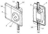
ベースユニット3の各々は、図2に示すように、その背面部に電力線L1と情報線L2に接続される端子(30a, 32a)と送り配線用端子(30b, 32b)が設けられる。図3に示すように、ベースユニット3は、スイッチボックス2にネジなどの取付部材を用いて固定される。図3中、番号12はベースユニットの正面に着脱可能に取り付けられる化粧カバーであり、番号11は化粧カバー12と個別に設けられるコンセントカバーである。ベースユニット3の内部に配置される回路構成は、機能ユニット4に電力および情報信号を伝送するために設計される。例えば、図2のベースユニット3は、AC/ACコンバータ60、直流電源部61、送受信部62、E/O変換部63、O/E変換部65、および機能部67を有する。 As shown in FIG. 2, each
AC/ACコンバータ60は、商用電源ACを周波数の高い低圧交流電圧に変換し、この低圧交流電圧をコア70に巻装したコイル72に印加する。直流電源部61は、低圧交流電圧を整流平滑して得られる安定した直流電圧から内部回路部品の動作電圧を生成する。送受信部62は、情報線L2を介して双方向コミュニケーションを可能にするため情報信号を送受信する。E/O変換部63は、情報線を介して受信される情報信号を光学信号に変換し、この光学信号を発光素子(LED)64を介して出力する。一方、O/E変換部65は、機能ユニット5など外部から送られてくる光信号を受光素子(PD)66で受光し、受光した光学信号を情報信号に変換して送受信部62に送る。図2において、番号67は、電源コンセントのような機能部である。The AC /
また、図4に示す別のベースユニット3を使用してもよい。このベースユニット3は、上記電力線L1と情報線L2に接続される端子(30a, 32a, 30b, 32b)を有するゲートハウジング31と、機能ユニット4に着脱可能に接続されるメインハウジング33とで構成される。ゲートハウジング31とメインハウジング33は、互いに着脱可能に接続され、ゲートハウジングからメインハウジングへの給電と、ゲートハウジングとメインハウジングとの間での情報伝送の両方を同時に確立する一対のモジュールポート34とモジュールコネクタ42を有する。尚、メインハウジング33の代わりに、モジュールコネクタ42を有する別の機能ユニットをゲートハウジング31のモジュールポート34に着脱可能に接続してもよい。この場合は、モジュールポート34を有するゲートハウジング31が、ベースユニットの定義を満たす。 Further, another
ゲートハウジング31の前面に設けられるモジュールポート34は、図5(b)に示すように、電力を供給するための電力ポート34aと、情報線L2にアクセスするための情報信号ポート34bとで構成される。モジュールポート34において、電力ポート34aと情報信号ポート34bの配置およびそれらの形状は、デュアル配線システムにおいて標準化(規格化)される。例えば、図5(b)に示すように、電力ポート34aと情報信号ポート34bの各々は略矩形形状を有し、互いに平行に配置される。 As shown in FIG. 5B, the
一方、メインハウジング33の背面に形成されるモジュールコネクタ42は、図4および図5(a)に示すように、電力コネクタ42aと情報信号コネクタ42bとで構成される。モジュールコネクタ42において、電力コネクタ42aと情報信号コネクタ42bの配置およびそれらの形状は、デュアル配線システムにおいて標準化(規格化)される。例えば、図5(a)に示すように、電力コネクタ42aと情報信号コネクタ42bの各々は略矩形形状を有し、互いに平行に配置される。 On the other hand, the
本実施形態において、モジュールポート34は、電力ポート34aと情報信号ポート34bの周囲に設けられる環状壁や環状溝のようなガイド部35を有する。このガイド部35は、メインハウジング33の背面に形成されるモジュールコネクタ42の環状壁のような係止部45に係止可能に形成される。係止部45をガイド部35に係止させることにより、電力コネクタ42aと情報信号コネクタ42bが電力ポート34aと情報信号ポート34bに同時に接続されるので、メインハウジング33の着脱性を改善することができる。モジュールポート34とモジュールコネクタ42は、雄雌コネクタで形成してもよい。 In the present embodiment, the
また、図4のベースユニット3は、機能部67として、センサ機能やコントローラ機能を有するように設計される。すなわち、演算処理部68およびI/Oインターフェース69が送受信部62と機能部67の間に形成される。演算処理部68は、送受信部62で受信された情報信号の信号処理を実行し、処理された信号をI/Oインターフェース69を介して機能部67に送信する機能や、機能部67から送られてくるデータ信号をI/Oインターフェース69を介して受信し情報信号として出力する機能を有する。送受信部62、演算処理部68および機能部67の動作に必要な電力は直流電源部61から供給される。商用電源ACを所定電圧の直流に変換するAC/DC変換部をAC/AC変換部60の代わりに用いれば、直流電源部61を省略することができる。図4における他の回路構成は、図2のものと実質的に同じであるので、重複する説明を省略する。 4 is designed to have a sensor function and a controller function as the
機能ユニット4は、ベースユニット3を介して機能ユニット4に提供される電力と、ベースユニット3を介しての機能ユニット4と情報線L2の間における情報信号の双方向コミュニケーションを利用して種々の機能を提供するように設計される。例えば、機能ユニット4が天井に近い位置の壁面に組み込まれたベースユニット3に接続される場合、機能ユニットは、照明器具の引掛けプラグを接続するためのコンセント機能、動体センサ、温度センサ、監視カメラなどの防犯機能、スピーカのような音響機能を有するのが好ましく、使用者が楽に操作できる中位の高さの壁面に組み込まれたベースユニット3に機能ユニット4が接続される場合、照明器具のON/OFFスイッチ機能や、空調機等の電気製品の制御機能、液晶のような表示機能を有することが好ましく、さらに機能ユニット4が床に近い低い位置で壁面に組み込まれたベースユニット3に接続される場合、電気掃除機のような電気機器のプラグ接続用コンセント機能や、スピーカ等の音響機能や足元灯機能を有することが好ましい。 The
具体的には、図6に示すように、機能部81がスイッチ機能を有する場合、スイッチを操作することにより生成された操作データがI/Oインターフェース89を介して演算処理部88に送られる。ついで、処理情報が送受信部87を通じて、例えば赤外線リモコン送信部(図示せず)に送られ、その結果、操作対象の電気機器は、赤外線リモコン送信部から発信されるリモコン信号によりON/OFFされる。機能部81がセンサで形成される場合、センサの検知したデータが情報信号として情報線L2に送信され、所望の通報機器によって使用者に通知される。機能部81がスピーカで形成される場合は、情報信号として送られてくる音声データがスピーカから出力される。機能部81が監視カメラで形成される場合は、監視カメラによって撮像された画像データの圧縮符号化が実施され、情報信号として出力される。さらに、機能部81がモニタで形成される場合は、情報線L2を介して提供される画像データが解読され、モニタ装置上に表示される。機能部81が電源コンセントである場合は、演算処理部88やI/Oインターフェース89を省略することができる。このように、本発明のデュアル配線システムにおいては、種々の機能部81を有する機能ユニット4を着脱可能に使用できるので、機能ユニット4のレイアウト自由度が大きく改善される。 Specifically, as shown in FIG. 6, when the
ベースユニット3内のコア70に巻装されたコイル72は、ベースユニット3から機能ユニット4に電力を非接触で供給するための給電手段として使用される。すなわち、ベースユニット3のコア70に巻装されたコイル72は、トランスの一次側に相当する電磁結合部を提供する。一方、図6に示すように、機能ユニット4は、コア80に巻装されたコイル82でなり、トランスの2次側として機能する電磁結合部を有する。したがって、ベースユニット3と機能ユニット4の間に電磁結合を形成することにより、機能ユニット4のコイルに82に低圧交流電圧が誘起され、ベースユニット3から機能ユニット4への電力供給が達成される。尚、本実施形態においては、商用周波数よりも周波数が高い低圧交流電圧がAC/ACコンバータ60によって得られるので、トランスとして使用される電磁結合部を小型化することができる。 The
また、ベースユニット3のE/O変換部の63発光素子(LED)64は、機能ユニット4に情報信号として光信号を非接触で伝達する。この場合、機能ユニット4をベースユニット3に接続した時、ベースユニット3の発光素子64が機能ユニット4の受光素子86と対面関係となるように機能ユニット4内に受光素子(PD)86が配置される。同様に、機能ユニット4からベースユニット3に情報信号として光信号を伝送するために、機能ユニット4は、ベースユニット3との接続時において、ベースユニット3の受光素子(PD)66と対面関係となるように配置される発光素子(LED)84を有する。このように、ベースユニット3と機能ユニット4の各々が、光結合部として、一対のE/O変換部(63,83)とO/E変換部(65, 85)を有し、両者間の情報信号の双方向コミュニケーションを可能にしている。 Further, the 63 light emitting element (LED) 64 of the E / O conversion unit of the
図2および3に示すように、給電に使用される電磁結合部Xと情報信号の相互コミュニケーションに使用される光学結合部Yは、各ベースユニット3の側面に互いから所定間隔離して設けられる。また、電磁結合部Xと光学結合部Yの形状は、ベースユニット3の各々が複数の機能ユニット4の間で共用されるように定形化(規格化)されている。また、図6に示すように、電磁結合部Xと光学結合部Yのペアを、機能ユニット4の両側面の各々に設けることが好ましい。すなわち、機能ユニット4の一側(例えば、左側)の光学結合部Y1は、上側に配置される受光素子86と、下側に配置される発光素子84とで構成され、機能ユニット4の他側(例えば、右側)の光学結合部Y2は、上側に配置される発光素子94と、下側に配置される受光素子96とで構成される。 As shown in FIGS. 2 and 3, the electromagnetic coupling portion X used for power feeding and the optical coupling portion Y used for mutual communication of information signals are provided on the side surfaces of the
この場合は、複数の機能ユニット4が直列にベースユニット3に接続される場合であっても、機能ユニット4とベースユニット3の間と同様に、機能ユニット4同士の間での情報信号の双方向コミュニケーションを確保することができる。また、それぞれの光学結合部(Y,Y1, Y2)には、光学装置を保護するために、透光性カバーを取り付けることが好ましい。図6に示すように、機能ユニット4は、隣接する機能ユニット4間における電力の供給と情報信号の相互コミュニケーションを達成するための回路部品を有するが、これらはベースユニット3に使用される回路部品と実質的に同じであるので、同じ回路部品に関する重複する説明については省略する。 In this case, even when a plurality of
図3に示すように、機能部67(例えば、電力コンセント)をベースユニット3の正面に設けるとともに、ベースユニット3の側面に一対の電磁結合部Xと光学結合部Yのペアを設けることで、機能ユニット4を壁面に沿って(すなわち、壁面と平行に)ベースユニット3に接続することができる。したがって、室内空間の美観を損なうことなく、デュアル配線システムにおける機能拡張性を向上することができる。 As shown in FIG. 3, a functional unit 67 (for example, a power outlet) is provided on the front surface of the
以下に、ベースユニット3に接続された機能ユニット4の例を紹介する。図7(a)および図7(b)においては、ベースユニット3が機能部67として照明器具の引掛栓刃用コンセントを有し、機能ユニット4は、赤外リモコン信号の発信機能を有する。この場合、機能部67としてコントローラを有する別の機能ユニットが使用者によって操作された時に得られる操作データが信号線L2を介して図7(a)の機能ユニット4に送られ、それにより赤外リモコン信号が空調機器のような電気機器の赤外リモコン信号受信部に向けて発信される。図7(a)において、番号58は、使用しない時に電磁結合部Xおよび光学結合部Yを保護するため、機能ユニット4の側面に着脱可能に取り付けられる保護カバーである。また、ベースユニット3が電源コンセントを有する場合、電源コンセントの回路にリレー接点や半導体スイッチを接続し、別の機能ユニットからの伝送される制御信号に基づいてリレー接点や半導体スイッチが動作される時にコンセント機能が中止されるようにしてもよい。 Hereinafter, an example of the
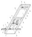
図8に示す参考例では、第1〜第3機能ユニット(4A,4B,4C)がベースユニット3に接続される。このベースユニット3は機能部を有していない。ベースユニット3に着脱自在に接続される第1機能ユニット4Aが空調機器をON/OFFするためのスイッチを機能部81として有し、第1機能ユニット4Aに着脱自在に接続される第2機能ユニット4Bが空調機器のコントローラを機能部81として有し、第2機能ユニット4Bに着脱自在に接続される第3機能ユニット4Cがインターホンの親機を機能部81として有する。In thereference example shown in FIG. 8, the first to third functional units (4A, 4B, 4C) are connected to the
第1機能ユニット4Aは、運転ボタンB1と、停止ボタンB2と、これらのボタン操作に基づいてのデータを作成し、演算処理部にI/Oインターフェースを介して送るCPU部とで構成される。この機能ユニットは照明器具の操作に好適である。第2機能ユニット4Bは、空調機器用温度設定ダイヤル51と、設定温度表示用液晶モニタ52と、空調機器を一定時間動作させるためのタイマースイッチ53と、設定ダイヤル51およびタイマースイッチ53の動作に基づいて運転データを作成し、演算処理部にI/Oインターフェースを介して送るとともに、液晶モニタ52に表示されるデータを作成するCPU部とで構成される。 The first
第3機能ユニット4Cは、音量調整ボタンB3と、スピーカ54と、スピーカの送話機能と受話機能を切り替えるためのモードスイッチ55と、玄関に配置されたTVカメラによって撮像された映像を表示する液晶モニタ56と、玄関扉のロックを解除するための解除ボタンB4と、スピーカの音声処理機能と、液晶モニタの映像処理機能と、解除ボタンやモードスイッチの動作に基づいて作成された操作データをI/Oインターフェースを介して演算処理部に送る機能等を有するCPU部とで構成される。尚、機能ユニット4の機能部81は、上記例示に限定されない。例えば、電気カミソリ、電動歯ブラシ、携帯電話、携帯オーディオプレーヤー等の充電器を機能部として設けても良い。また、インターホンの子機機能を有する機能ユニット4を玄関の外壁面に組み込んだベースユニット3に接続しても良い。 The third
上記説明においては、ベースユニット3は、スイッチボックス2内に直接固定されているが、必要に応じて、例えば、図9に示すように、取付板75を介してベースユニット3をスイッチボックス2に固定しても良い。この場合、取付板75の両側に設けたフックをベースユニット3に係止させた後、ベースユニット3が保持された取付板75がスイッチボックス2にネジ止めされる。あるいは、スイッチボックス2を用いることなく、専用の取付金具を用いてベースユニット3を壁面に直接固定しても良い。ベースユニットを壁面に組み込んだ後、ベースユニット3のハウジング10の前面にコンセントカバー11および化粧カバー12が取り付けられる。 In the above description, the
また、機能ユニット4は、ベースユニット3に図10(a)に示すように取り付けられる。すなわち、化粧カバー12がまずベースユニット3から除去される。本実施形態においては、コンセントカバー11を化粧カバー12と個別に形成しているので、機能ユニット4の着脱作業中、コンセントカバー11によって電気コンセントのような機能部67の偶発的な破損を防止することができる。機能ユニット4がベースユニット3の側面に、機能ユニット4の電磁結合部Xと光学結合部Yがベースユニット3のそれらに対面関係となるように配置された後、機能ユニット4が連結部材90によりベースユニット3に機械的に連結される。ベースユニット3および機能ユニット4の各々のハウジング(10,20)は、上下両端部に水平ガイドレール(14, 24)を有する。番号15は、ガイドレールの長さ方向の略中央位置に設けられるストッパ壁である。一方、図10(b)に示すように、連結部材90は、それぞれのガイドレール(14,24)を嵌め込み可能な溝92を有する。 The
図10(a)に示すように、ガイドレール14が溝92に嵌め込まれている状態で、連結部材90をストッパ壁15に接触するまでスライド移動させる。これにより、連結部材90はその約半分の長さにわたってベースユニット3に係止される。一方、連結部材90は、その残りの長さにわたって上記と同様に機能ユニット4に係止される。このように、連結部材90とベースユニット3間の係止と連結部材90と機能ユニット4間の係止が上下両端部で完了された後、化粧カバー(12,22)がベースユニット3およぶ機能ユニット4の前面に取り付けられる。連結部材90は化粧カバー(12, 22)とベースユニット3および機能ユニット4のハウジング(10,20)との間に保持されるので、連結部材90の偶発的な落下を防止して、両者の間の安定した機械的接続を美観を損なうことなく得ることができる。 As shown in FIG. 10A, in a state where the
以下は、ベースユニット3と機能ユニット4の間や、隣接する機能ユニット4同士の間に安定した機械的接続を得るための手段の変更例である。 The following is a modified example of means for obtaining a stable mechanical connection between the
本実施形態の第1変更例にかかる機能ユニット4は、図11(a)〜図11(c)に示すように、各々が電磁結合部Xと光学結合部Yでなる一対の雄型コネクタ25と雌型コネクタ27をその両側面に有する。この場合は、雄型コネクタ25と雌型コネクタ27はモジュールコネクタとモジュールポートとみなすことができる。ベースユニットは、機能ユニットとの接続のために同じ雄型コネクタと雌型コネクタを有しているので、ベースユニットと機能ユニットの間の電力伝送及び信号伝送が電磁結合および光学結合により非接触式に行われる。例えば、雄型コネクタ25がベースユニット3に設けられる雌型コネクタに着脱可能に接続され、雌型コネクタ27が別の機能ユニット4に形成される雄型コネクタに着脱可能に接続される。この機能ユニット4はさらに水平溝26を有し、この水平溝に相似形状の断面を有する連結部材90Aが嵌め込まれる。図10(b)の連結部材90と同様に、連結部材90Aの一端が、その約半分の長さにわたって機能ユニット4の溝内に挿入され、連結部材90Aの他端が残り半分の長さにわたって隣接するベースユニット3あるいは別の機能ユニット4に設けられた溝に挿入され、それらの間に安定した機械的結合を提供する。 As shown in FIGS. 11A to 11C, the
本変更例においては、上記溝26が略台形断面を有するとともに、機能ユニット4の背面に設けられた開口が、前記台形断面の短辺に対応するので、化粧カバーを使用しなくても溝26からの連結部材90Aの落下を防ぐことができる。また、機能ユニット4の背面に設けた開口を介して連結部材90Aにアクセスすることができるので、溝26内において連結部材90Aのスライド移動を容易に行うことができる。尚、溝の形状は、機能ユニット4の背面に設けた開口を介して連結部材90Aが外れなければ台形断面に限定されない。 In this modified example, the
図12(a)に示すように、電磁結合部Xのみが雄型コネクタおよび雌型コネクタによって形成されても良い。機能ユニット4の拡張性を確保するために、雄型コネクタが機能ユニット4の一側に形成される場合、雌型コネクタが機能ユニットの他側に形成される。あるいは、図12(b)に示すように、電磁結合部Xと光学結合部Yの各々を、円弧状の凹部および凸部でなる雌型コネクタおよび雄型コネクタによって形成しても良い。このように、雄型コネクタおよび雌型コネクタの使用は、隣接する機能ユニット間における正確な位置決めをもたらし、結果的に、電力の供給と情報信号の相互コミュニケーションの信頼性を改善する。 As shown in FIG. 12A, only the electromagnetic coupling portion X may be formed by a male connector and a female connector. In order to ensure the expandability of the
また、本実施形態の第2変更例として、機能ユニット4の上下両端部は、図に13(a)に示すように、係止溝23を有するテーパ部21を有し、連結部材90Bは、前記テーパ部21に摺動接触するとともに、一端に係止溝23に嵌め込まれるフック93を有するように形成されることが好ましい。この場合は、機能ユニットの上下両端部それぞれにおいてテーパ部21に連結部材90Bがはめ込まれた後、図13(a)の矢印で示されるように、隣接する機能ユニットに向けて連結部材90Bをスライドさせる。これにより、図13(b)に示すように、隣接する機能ユニット4間の安定した機械的接続が連結部材90Bの使用によって得られる。 As a second modification of the present embodiment, the upper and lower end portions of the
本実施形態の第3の変更例として、図14(a)〜図14(c)に示すように、機能ユニット4の上下両端部の各々は、連結部材90Cを収納する凹部28と、一端で機能ユニット4のハウジング20に回動可能に保持されるカバー部材16とを有することが好ましい。連結部材90Cは、凹部28内に形成されるガイドレール24Cが摺動可能に嵌め込まれる溝92Cを有する。この場合は、連結部材90Cにアクセスするためにカバー部材16が開かれた後、図10(a)の場合と同様に、ガイドレール24Cに沿って連結部材90Cをスライド移動させる。最後に、カバー部材16を閉めれば、隣接する機能ユニット4間に安定した機械的接続が得られる。また、連結部材90Cは常に凹部28内に収納されるので、連結部材を紛失する心配がない。 As a third modification of the present embodiment, as shown in FIGS. 14 (a) to 14 (c), each of the upper and lower ends of the
尚、本発明のデュアル配線システムに使用される情報信号伝送方式としては、ベースバンド伝送またはブロードバンド伝送の一方を使用できる。また、プロトコルは特に限定されない。例えば、インターホンの親機、子機との間において双方向コミュニケーションを得るには、JT−H232パケットに基づいて音声/映像信号を送受信してもよい。また、制御系においては、操作データに基づいて制御が1対1または1対Nの制御比で行われるユニキャストやブロードキャストのための経路制御プロトコルを採用することも好ましい。あるいは、ベースユニット間の使用プロトコルと、ベースユニットに接続される機能ユニットで使用されるプロトコルが異なり、プロトコル変換がベースユニットで行われることも好ましい。 As an information signal transmission method used in the dual wiring system of the present invention, either baseband transmission or broadband transmission can be used. The protocol is not particularly limited. For example, in order to obtain two-way communication between a master unit and a slave unit of an interphone, audio / video signals may be transmitted and received based on JT-H232 packets. In the control system, it is also preferable to employ a unicast or broadcast path control protocol in which control is performed at a control ratio of 1: 1 or 1: N based on operation data. Alternatively, it is also preferable that the protocol used between the base units is different from the protocol used in the functional unit connected to the base unit, and the protocol conversion is performed in the base unit.
図1に示すように、種々の機能を有する機能ユニット4の各々が複数のベースユニット3の所望の一つに着脱可能に接続され、それによりベースユニット3から機能ユニット4への電力供給と、ベースユニット3と機能ユニット4の間における情報信号の双方向コミュニケーションの両方が同時に確立されるので、一般のユーザーは、すでにベースユニット3の一つに取り付けられている機能ユニット4を面倒な補修作業を実施することなく別の機能ユニット4に容易に交換することができる。また、複数の機能ユニット4を壁面に沿ってベースユニット3に接続する場合は、室内空間の美観を損なうことなく、機能拡張性をさらに改善することができる。このように、本発明のデュアル配線システム用ベースユニットは、情報化社会において使用者のニーズに合った快適で便利な生活/作業環境を提供するのに有効である。 As shown in FIG. 1, each of the
Claims (5)
Translated fromJapanese前記ベースユニットは、前記複数種類の機能ユニットの間で共用されるように定型化されたモジュールポートとモジュールコネクタの一方を有し、機能ユニットに設けたモジュールポートとモジュールコネクタの他方と着脱可能に接続されて、ベースユニットから機能ユニットへの給電と、ベースユニットと機能ユニットとの間での信号伝送の両方を同時に確立し、それにより前記機能ユニットに、電力線からの電力の供給、情報線からの情報の出力、および情報線への情報の入力の少なくとも一つの機能を提供し、
前記ベースユニットは、電力線と情報線に接続される端子を設けた背面部と、電気機器のコンセントが挿入される電源コンセントおよび電気機器をON/OFFするためのスイッチの少なくとも一つを有する正面部と、上記機能ユニットが壁面に沿う方向にベースユニットに着脱可能に接続されるように上記モジュールコネクタおよびモジュールポートの一方を有する側面部とを含むハウジングを有するとともに、
前記機能ユニットは、ベースユニットの側面部と対向する側面に、上記モジュールコネクタおよびモジュールポートの他方を有することを特徴とするデュアル配線システム用ベースユニット。It is embedded in the wall of the building and is used by connecting to both the power line and the information line arranged in the building, and any one of a plurality of types of functional units having various functional parts inherently connected thereto. A base unit for a dual wiring system,
The base unit has one of a module port and a module connector that are standardized so as to be shared among the plurality of types of functional units, and is detachable from the module port and the other of the module connectors provided in the functional unit. Connected to establish both power supply from the base unit to the functional unit and signal transmission between the base unit and the functional unit at the same time, thereby supplying power from the power line to the functional unit from the information line Providing at least one function of outputting information and inputting information to the information line,
The base unit has a rear part provided with terminals connected to the power line and the information line, a front part having at least one of a power outlet into which an outlet of the electric device is inserted and a switch for turning on / off the electric device. And a housing including a side part having one of the module connector and the module port so that the functional unit is detachably connected to the base unit in a direction along the wall surface,
The functional unit has the other of the module connector and the module port on a side surface opposed to a side surface portion of the base unit.
Applications Claiming Priority (6)
| Application Number | Priority Date | Filing Date | Title |
|---|---|---|---|
| JP2005200991AJP2007020349A (en) | 2005-07-08 | 2005-07-08 | Gate device |
| JP2005200990AJP2007020014A (en) | 2005-07-08 | 2005-07-08 | Wiring system |
| JP2005200992AJP2007020015A (en) | 2005-07-08 | 2005-07-08 | Functional device |
| JP2005200993AJP2007018941A (en) | 2005-07-08 | 2005-07-08 | Functional module |
| JP2005200994AJP4710447B2 (en) | 2005-07-08 | 2005-07-08 | Wiring system |
| PCT/JP2005/024200WO2007007432A1 (en) | 2005-07-08 | 2005-12-22 | Base unit for dual wiring system |
Publications (2)
| Publication Number | Publication Date |
|---|---|
| JP2008533649A JP2008533649A (en) | 2008-08-21 |
| JP4740127B2true JP4740127B2 (en) | 2011-08-03 |
Family
ID=36123215
Family Applications (5)
| Application Number | Title | Priority Date | Filing Date |
|---|---|---|---|
| JP2006515421AExpired - Fee RelatedJP4740127B2 (en) | 2005-07-08 | 2005-12-22 | Base unit for dual wiring system |
| JP2006515410AExpired - Fee RelatedJP4311445B2 (en) | 2005-07-08 | 2005-12-22 | Functional unit for dual wiring system |
| JP2006515411AExpired - Fee RelatedJP4311446B2 (en) | 2005-07-08 | 2005-12-22 | Dual wiring system |
| JP2006515414AExpired - Fee RelatedJP4424349B2 (en) | 2005-07-08 | 2005-12-22 | Dual wiring system |
| JP2006515412AExpired - Fee RelatedJP4618248B2 (en) | 2005-07-08 | 2005-12-27 | Dual wiring system |
Family Applications After (4)
| Application Number | Title | Priority Date | Filing Date |
|---|---|---|---|
| JP2006515410AExpired - Fee RelatedJP4311445B2 (en) | 2005-07-08 | 2005-12-22 | Functional unit for dual wiring system |
| JP2006515411AExpired - Fee RelatedJP4311446B2 (en) | 2005-07-08 | 2005-12-22 | Dual wiring system |
| JP2006515414AExpired - Fee RelatedJP4424349B2 (en) | 2005-07-08 | 2005-12-22 | Dual wiring system |
| JP2006515412AExpired - Fee RelatedJP4618248B2 (en) | 2005-07-08 | 2005-12-27 | Dual wiring system |
Country Status (4)
| Country | Link |
|---|---|
| US (5) | US8138636B2 (en) |
| JP (5) | JP4740127B2 (en) |
| KR (5) | KR100944743B1 (en) |
| WO (5) | WO2007007430A1 (en) |
Families Citing this family (70)
| Publication number | Priority date | Publication date | Assignee | Title |
|---|---|---|---|---|
| US7475440B2 (en) | 2001-07-10 | 2009-01-13 | Chaffee Robert B | Inflatable device forming mattresses and cushions |
| KR100944743B1 (en)* | 2005-07-08 | 2010-03-03 | 파나소닉 전공 주식회사 | Base unit for double wiring system |
| WO2007115316A2 (en) | 2006-04-04 | 2007-10-11 | Chaffee Robert B | Method and apparatus for monitoring and controlling pressure in an inflatable device |
| US7612653B2 (en)* | 2006-08-01 | 2009-11-03 | Tyco Electronics Corporation | Wall-mounted network outlet |
| KR100913186B1 (en)* | 2007-12-27 | 2009-08-20 | 주식회사 애니텍 | Carbon dioxide removal device, carbon dioxide recovery device and carbon dioxide removal and recovery device emitted from natural gas vehicle |
| WO2009114822A2 (en) | 2008-03-13 | 2009-09-17 | Chaffee Robert B | Method and apparatus for monitoring and controlling pressure in an inflatable device |
| US8598993B2 (en)* | 2008-08-15 | 2013-12-03 | Homerun Holdings Corporation | Method for wiring devices in a structure using a wireless network |
| US8175463B2 (en)* | 2008-09-24 | 2012-05-08 | Elbex Video Ltd. | Method and apparatus for connecting AC powered switches, current sensors and control devices via two way IR, fiber optic and light guide cables |
| US20110227696A1 (en)* | 2008-12-05 | 2011-09-22 | Kazuhiko Miyata | Operation system |
| DE202008016394U1 (en)* | 2008-12-12 | 2010-04-22 | Weidmüller Interface GmbH & Co. KG | Modular electronics package |
| US8145327B2 (en)* | 2009-03-13 | 2012-03-27 | Susan Banks | Method and apparatus for implementing a consumer-configurable modular electrical system |
| ES2704647T3 (en)* | 2009-03-17 | 2019-03-19 | Mitsubishi Electric Corp | Input / output device and remote controller |
| US9130400B2 (en) | 2009-09-24 | 2015-09-08 | Apple Inc. | Multiport power converter with load detection capabilities |
| US8658893B1 (en)* | 2010-03-22 | 2014-02-25 | Hubbell Incorporated | Electrical device with interchangeable faceplates |
| JP5694694B2 (en)* | 2010-07-02 | 2015-04-01 | 大和ハウス工業株式会社 | Building media playback system |
| US9760140B1 (en) | 2010-07-03 | 2017-09-12 | Best Energy Reduction Technologies, Llc | Method, system and apparatus for monitoring and measuring power usage by a device |
| US8093751B1 (en) | 2010-07-03 | 2012-01-10 | Green Power Technologies, Llc | Method and system for controlling power to an electrically powered device |
| US9007186B1 (en) | 2010-07-03 | 2015-04-14 | Best Energy Reduction Technologies, Llc | Method and apparatus for controlling power to a device |
| US9331524B1 (en)* | 2010-07-03 | 2016-05-03 | Best Energy Reduction Technologies, Llc | Method, system and apparatus for monitoring and measuring power usage |
| US7964989B1 (en) | 2010-09-09 | 2011-06-21 | Green Power Technologies, Llc | Method and system for controlling power to an electrically powered device |
| US8755172B1 (en)* | 2011-01-21 | 2014-06-17 | Reliance Controls Corporation | Modular housing for a transfer switch having panel-mounted power transfer switching components |
| WO2012158787A2 (en) | 2011-05-17 | 2012-11-22 | 3M Innovative Properties Company | Remote socket apparatus |
| JP5776487B2 (en)* | 2011-10-13 | 2015-09-09 | ソニー株式会社 | Power control apparatus and program |
| EP2621050B1 (en)* | 2012-01-27 | 2015-04-08 | Braun GmbH | Inductive Charger for Hand-Held Appliances |
| MX337947B (en)* | 2012-03-12 | 2016-03-29 | Norman R Byrne | Electrical energy management and monitoring system, and method. |
| FR3000310B1 (en)* | 2012-12-20 | 2014-12-26 | Legrand France | ELECTRICAL EQUIPMENT MODULE |
| FR3000308B1 (en)* | 2012-12-20 | 2015-01-09 | Legrand France | REMOVABLE ELECTRICAL EQUIPMENT MODULE, ELECTRIC BOX HAVING SUCH AN APPARATUS MODULE, AND METHOD OF REPLACING SUCH A MODULE OF APPARATUS |
| US9148005B2 (en) | 2013-03-14 | 2015-09-29 | Liberty Hardware Mfg. Corp. | Wall mounted electrical device cover plate assembly |
| US9965007B2 (en)* | 2013-08-21 | 2018-05-08 | N2 Global Solutions Incorporated | System and apparatus for providing and managing electricity |
| US9018803B1 (en)* | 2013-10-04 | 2015-04-28 | Elbex Video Ltd. | Integrated SPDT or DPDT switch with SPDT relay combination for use in residence automation |
| BR102015011128A2 (en) | 2014-05-19 | 2017-11-28 | R. Byrne Norman | BRANCHED ELECTRIC SYSTEM AND HIGH SEAT DENSITY AREA |
| CN204156972U (en)* | 2014-10-31 | 2015-02-11 | 京东方科技集团股份有限公司 | A kind of television set and console indicator unit |
| US20160172808A1 (en)* | 2014-12-16 | 2016-06-16 | Leviton Manufacturing Co., Inc. | Combined audio/video and alternating current (ac) power module |
| US10139790B2 (en) | 2015-06-10 | 2018-11-27 | Vivint, Inc. | Powered faceplate integration |
| US10042342B1 (en) | 2015-10-08 | 2018-08-07 | Best Energy Reduction Technologies, Llc | Monitoring and measuring power usage and temperature |
| US11209845B2 (en)* | 2016-03-17 | 2021-12-28 | Jean-Louis Iaconis | Modular wall-mounted electrical control device |
| CN105826119B (en)* | 2016-03-31 | 2018-04-06 | 中车青岛四方机车车辆股份有限公司 | Alarm tripper |
| US10425236B2 (en) | 2016-10-05 | 2019-09-24 | Norman R. Byrne | Intelligent electrical power distribution system |
| MX371369B (en) | 2016-10-07 | 2020-01-28 | Norman R Byrne | Electrical power cord with intelligent switching. |
| MX393315B (en) | 2016-10-07 | 2025-03-24 | Norman R Byrne | Rugged weather resistant power distribution |
| US10727731B1 (en) | 2017-04-01 | 2020-07-28 | Smart Power Partners, LLC | Power adapters adapted to receive a module and methods of implementing power adapters with modules |
| US12093004B1 (en) | 2017-04-01 | 2024-09-17 | Smart Power Partners LLC | In-wall power adapter and method of implementing an in-wall power adapter |
| US10530597B1 (en) | 2017-04-01 | 2020-01-07 | Smart Power Partners LLC | System for controlling a plurality of power switches configured to apply power to devices |
| US12027968B2 (en) | 2017-04-01 | 2024-07-02 | John J. King | Power adapters and methods of implementing a power adapter |
| US10996645B1 (en) | 2017-04-01 | 2021-05-04 | Smart Power Partners LLC | Modular power adapters and methods of implementing modular power adapters |
| US11445626B2 (en)* | 2017-06-10 | 2022-09-13 | Hesam Shemirani | Power outlet module including USB plug in location other than outlet face |
| CN109119852A (en)* | 2017-06-23 | 2019-01-01 | 京东方科技集团股份有限公司 | Insert row |
| US11239647B2 (en)* | 2018-05-08 | 2022-02-01 | Christopher Davis | System for coupling accessories and/or components |
| US11404851B2 (en)* | 2018-05-29 | 2022-08-02 | Robot, S.A. | Building automation device which can be recessed in an electrical box |
| US11303079B2 (en) | 2019-05-28 | 2022-04-12 | Norman R. Byrne | Modular electrical system |
| CA3082616A1 (en) | 2019-06-07 | 2020-12-07 | Norman R. Byrne | Electrical power distribution system |
| US12045071B1 (en) | 2019-06-30 | 2024-07-23 | Smart Power Partners LLC | In-wall power adapter having an outlet |
| US10958020B1 (en) | 2019-06-30 | 2021-03-23 | Smart Power Partners LLC | Control attachment for an in-wall power adapter and method of controlling an in-wall power adapter |
| US11189948B1 (en) | 2019-06-30 | 2021-11-30 | Smart Power Partners LLC | Power adapter and method of implementing a power adapter to provide power to a load |
| US12066848B1 (en) | 2019-06-30 | 2024-08-20 | Smart Power Partners LLC | In-wall power adaper adapted to receive a control attachment and method of implementing a power adapter |
| US10965068B1 (en) | 2019-06-30 | 2021-03-30 | Smart Power Partners LLC | In-wall power adapter having an outlet and method of controlling an in-wall power adapter |
| US10938168B2 (en) | 2019-06-30 | 2021-03-02 | Smart Power Partners LLC | In-wall power adapter and method of controlling the application of power to a load |
| US12164350B1 (en) | 2019-06-30 | 2024-12-10 | Smart Power Partners LLC | Power adapter configured to provide power to a load |
| US11231730B1 (en) | 2019-06-30 | 2022-01-25 | Smart Power Power LLC | Control attachment for a power adapter configured to control power applied to a load |
| US11043768B1 (en) | 2019-06-30 | 2021-06-22 | Smart Power Partners LLC | Power adapter configured to provide power to a load and method of implementing a power adapter |
| US10917956B1 (en) | 2019-06-30 | 2021-02-09 | Smart Power Partners LLC | Control attachment configured to provide power to a load and method of configuring a control attachment |
| US10958026B1 (en)* | 2019-06-30 | 2021-03-23 | Smart Power Partners LLC | Contactless thermometer for an in-wall power adapter |
| US11201444B1 (en) | 2019-06-30 | 2021-12-14 | Smart Power Partners LLC | Power adapter having contact elements in a recess and method of controlling a power adapter |
| US11264769B1 (en) | 2019-06-30 | 2022-03-01 | Smart Power Partners LLC | Power adapter having contact elements in a recess and method of controlling a power adapter |
| US11460874B1 (en) | 2019-06-30 | 2022-10-04 | Smart Power Partners LLC | In-wall power adapter configured to control the application of power to a load |
| US11219108B1 (en) | 2019-06-30 | 2022-01-04 | Smart Power Partners LLC | Power adapter arrangement and method of implementing a power adapter arrangement |
| US11579640B1 (en) | 2019-06-30 | 2023-02-14 | Smart Power Partners LLC | Control attachment for an in-wall power adapter |
| US11424561B2 (en) | 2019-07-03 | 2022-08-23 | Norman R. Byrne | Outlet-level electrical energy management system |
| EP3772075B1 (en)* | 2019-07-31 | 2021-04-14 | GIRA GIERSIEPEN GmbH & Co. KG | Touch top for a bus coupler, corresponding operating device and corresponding method |
| US12160074B2 (en) | 2021-11-03 | 2024-12-03 | Smart Power Partners LLC | In-wall power adapter having a switch and a recess adapted to receive a control module |
Family Cites Families (77)
| Publication number | Priority date | Publication date | Assignee | Title |
|---|---|---|---|---|
| US2433917A (en)* | 1944-07-15 | 1948-01-06 | Mccartney William James | Outlet box and plug-in connections therefor |
| US3609647A (en)* | 1968-12-19 | 1971-09-28 | Angelo Castellano | Electrical receptacle |
| US3879101A (en)* | 1973-12-04 | 1975-04-22 | George T Mckissic | Electric Plug-In Module |
| DE3019668A1 (en)* | 1980-05-22 | 1981-11-26 | SIEMENS AG AAAAA, 1000 Berlin und 8000 München | DEVICE FOR DETECTING AND PROCESSING ELECTRICAL SIGNALS |
| JPS5860331A (en) | 1981-10-07 | 1983-04-09 | Hitachi Ltd | home information system |
| JPS6165555A (en) | 1984-09-05 | 1986-04-04 | Mitsubishi Electric Corp | Home control system and intercom system |
| US4842551A (en) | 1986-07-11 | 1989-06-27 | Heimann Anthony J | Modular connector assembly for electrical utility box |
| US4725249A (en)* | 1986-09-22 | 1988-02-16 | American Telephone & Telegraph Company | Connector assembly |
| JP2719133B2 (en)* | 1987-06-25 | 1998-02-25 | 松下電工株式会社 | Telecon switch system |
| JPH0371581A (en) | 1989-08-09 | 1991-03-27 | Hitachi Ltd | Photoelectric composite branch connector |
| US5241410A (en)* | 1990-06-21 | 1993-08-31 | Litephone Systems Ltd. | Enhanced infrared-connected telephone system |
| JPH0817506B2 (en) | 1990-08-01 | 1996-02-21 | 積水化学工業株式会社 | Functional unitized control panel for residential equipment |
| US5114365A (en)* | 1990-08-30 | 1992-05-19 | William H. Thompson | Wall plate |
| US5157531A (en)* | 1991-02-19 | 1992-10-20 | International Business Machines Corporation | Hybrid transmission network |
| FR2686142B1 (en) | 1992-01-14 | 1994-04-22 | Mavil | COMBINATION OF SUCCESSIVE SECTION OF PLASTIC CABLE TRAY AND MEANS FOR ASSEMBLING THE SAID SECTION, AND METHOD FOR IMPLEMENTING SUCH A COMBINATION. |
| JP3195664B2 (en) | 1992-08-26 | 2001-08-06 | 松下電工株式会社 | Remote control system |
| JP2573456B2 (en) | 1992-11-27 | 1997-01-22 | 松下電工株式会社 | Indoor wiring system |
| CH686465A5 (en)* | 1993-01-26 | 1996-03-29 | Royale Consultants Ltd | Method and apparatus for bidirectional Informationsuebertragung (full duplex). |
| US5383799A (en)* | 1993-03-26 | 1995-01-24 | Fladung; Philip E. | Multi-purpose plug-in electrical outlet adaptor |
| US5539821A (en)* | 1995-01-24 | 1996-07-23 | At&T Corp. | Power outlet mount for a portable telephone |
| DE29504491U1 (en) | 1995-03-16 | 1995-06-01 | Merten GmbH & Co. KG, 51674 Wiehl | Installation device for building system technology |
| JPH08298690A (en)* | 1995-04-25 | 1996-11-12 | Matsushita Electric Works Ltd | Information transmission system |
| US5650771A (en)* | 1995-04-25 | 1997-07-22 | Lee; Chung-Cheng | Electrical socket with monitoring unit for monitoring operating conditions |
| DE19544027C2 (en)* | 1995-11-25 | 1999-01-07 | Bernward Dr Zimmermann | Bus system, especially for electrical installation |
| US6036516A (en)* | 1995-12-11 | 2000-03-14 | Byrne; Norman R. | Electrical interconnection assembly with additional outlet receptacles |
| JP3356625B2 (en) | 1996-06-25 | 2002-12-16 | 松下電工株式会社 | Wiring equipment for multimedia |
| JPH10136104A (en) | 1996-10-29 | 1998-05-22 | Matsushita Electric Works Ltd | House information panel system |
| US6002937A (en)* | 1996-10-31 | 1999-12-14 | Motorola, Inc. | Method of and apparatus for communicating information signals |
| KR19980061153A (en) | 1996-12-31 | 1998-10-07 | 박병재 | Engine mounter |
| JP3627421B2 (en) | 1997-01-28 | 2005-03-09 | 松下電工株式会社 | Power connection device |
| KR19980061153U (en)* | 1997-03-21 | 1998-11-05 | 유기범 | Adapter for power extension |
| KR100229603B1 (en)* | 1997-04-15 | 1999-11-15 | 윤종용 | Computer system with cable for infrared transmission and reception |
| JPH10304467A (en) | 1997-04-28 | 1998-11-13 | Matsushita Electric Works Ltd | Terminal equipment for load control and load control system |
| JP3430877B2 (en) | 1997-09-16 | 2003-07-28 | 松下電器産業株式会社 | Terminal device and power supply device |
| JPH11187154A (en) | 1997-12-22 | 1999-07-09 | Matsushita Electric Works Ltd | Multimedia information panel |
| JP4163786B2 (en) | 1998-04-14 | 2008-10-08 | 株式会社ケアコム | Nurse call master unit |
| US6379182B1 (en) | 1998-11-27 | 2002-04-30 | Norman R. Byrne | Energy center with interchangeable support bases |
| AT413621B (en)* | 1998-12-22 | 2006-04-15 | Faller Josef | OPTICAL DATA REPEATER WITH POWER SUPPLY IN COMBINED CONSTRUCTION WITH A POWER SOCKET |
| US6420964B1 (en)* | 1999-03-25 | 2002-07-16 | Matsushita Electric Industrial Co., Ltd. | Informational outlet and lines collection module |
| JP2000306643A (en) | 1999-04-23 | 2000-11-02 | Matsushita Electric Works Ltd | Compound joint box for information and power |
| JP3306592B2 (en)* | 1999-05-21 | 2002-07-24 | 株式会社豊田中央研究所 | Microstrip array antenna |
| US6369707B1 (en)* | 1999-06-08 | 2002-04-09 | Dana L. Neer | Specific location public alert receiver |
| JP2000348825A (en) | 1999-06-08 | 2000-12-15 | Mitsubishi Electric Corp | Outlet |
| US6431765B1 (en)* | 1999-06-11 | 2002-08-13 | Cisco Technology Inc. | Distributed network repeater module and method |
| US20010046815A1 (en) | 2000-02-16 | 2001-11-29 | Luu Lionel V. | Method of providing electrical energy to devices without using prongs |
| DE60136820D1 (en)* | 2000-07-11 | 2009-01-15 | Thomson Licensing | POWER ADAPTER FOR A MODULAR POWER SUPPLY NETWORK |
| US6904149B2 (en)* | 2000-08-11 | 2005-06-07 | Corning Cable Systems Llc | Tool-less wall-mount distributed filter housing |
| US6759759B2 (en)* | 2000-08-29 | 2004-07-06 | Tamagawa Seiki Kabushiki Kaisha | Rotary contactless connector and non-rotary contactless connector |
| SE0003257D0 (en)* | 2000-09-13 | 2000-09-13 | Hesselbom Innovation & Dev Hb | Network comprising transducers between electrical and optical signals |
| US6544049B1 (en) | 2000-10-24 | 2003-04-08 | Worldcom, Inc. | Electrical unit for mating with an electrical box |
| US6429779B1 (en)* | 2000-12-26 | 2002-08-06 | Gino Petrillo | Telephone line monitoring and alarm apparatus |
| US6624532B1 (en)* | 2001-05-18 | 2003-09-23 | Power Wan, Inc. | System and method for utility network load control |
| US6993417B2 (en)* | 2001-09-10 | 2006-01-31 | Osann Jr Robert | System for energy sensing analysis and feedback |
| AU2003202467A1 (en) | 2002-01-07 | 2003-07-24 | Matsushita Electric Industrial Co., Ltd. | Surface type optical modulator and its manufacturing method |
| US7274303B2 (en)* | 2002-03-01 | 2007-09-25 | Universal Electronics Inc. | Power strip with control and monitoring functionality |
| US6855881B2 (en)* | 2002-06-26 | 2005-02-15 | Bahman Khoshnood | Combined communication and power cable with air cooling for network systems |
| US20040121648A1 (en)* | 2002-07-26 | 2004-06-24 | V-Squared Networks | Network device for communicating information |
| US7761555B1 (en)* | 2002-08-06 | 2010-07-20 | Richard Anthony Bishel | Internet/intranet-connected AC electrical box |
| JP4323782B2 (en)* | 2002-11-28 | 2009-09-02 | パナソニック株式会社 | Receiver circuit |
| JP2004191883A (en) | 2002-12-13 | 2004-07-08 | Nippon Telegr & Teleph Corp <Ntt> | Optical information outlet |
| US7420459B2 (en)* | 2003-01-28 | 2008-09-02 | Gateway Inc. | Powerline networking device |
| JP2004304617A (en)* | 2003-03-31 | 2004-10-28 | Daito Tec Kk | Local area network using hybrid cable |
| US7194639B2 (en)* | 2003-06-30 | 2007-03-20 | Tellabs Vienna, Inc. | Power adapter and broadband line extender system and method |
| US7136936B2 (en) | 2003-10-03 | 2006-11-14 | Asoka Usa Corporation | Method and system for virtual powerline local area networks |
| US20050094786A1 (en)* | 2003-11-03 | 2005-05-05 | Ossa Cristian A. | Programmable timer for electrical or electronic apparatus |
| US7141736B2 (en)* | 2003-12-12 | 2006-11-28 | Gary Dean Plankell | Apparatus for mounting a telephone or other cordless device in a building structure and related methods |
| WO2005076871A2 (en) | 2004-02-04 | 2005-08-25 | Lombardi John L | Lapping composition and method using same |
| IL160417A (en) | 2004-02-16 | 2011-04-28 | Mosaid Technologies Inc | Outlet add-on module |
| US7592719B2 (en)* | 2004-02-25 | 2009-09-22 | Panamax | Protection of A/V components |
| US7034225B2 (en) | 2004-03-09 | 2006-04-25 | Scott Randall Thompson | Apparatus that enables low cost installation of a secure and tamper proof assembly that accommodates lifeline support for power line communication devices |
| US20060270284A1 (en)* | 2005-05-27 | 2006-11-30 | Youden John J | AC power network LAN interface module |
| KR100944743B1 (en)* | 2005-07-08 | 2010-03-03 | 파나소닉 전공 주식회사 | Base unit for double wiring system |
| JPWO2007060753A1 (en)* | 2005-11-25 | 2009-05-07 | パナソニック電工株式会社 | Voice information processing apparatus and wiring system using the same |
| US7425677B2 (en) | 2006-07-12 | 2008-09-16 | Advanced Currents Corp. | Closed electrical enclosure |
| US7697268B2 (en)* | 2007-08-09 | 2010-04-13 | Haworth, Inc. | Modular electrical distribution system for a building |
| WO2009070062A1 (en)* | 2007-11-29 | 2009-06-04 | Telefonaktiebolaget Lm Ericsson (Publ) | Adapter, arrangement and method |
| JP2010136244A (en)* | 2008-12-08 | 2010-06-17 | Toshiba Corp | Transmission circuit and complementary optical wiring system |
- 2005
- 2005-12-22KRKR1020087002541Apatent/KR100944743B1/ennot_activeExpired - Fee Related
- 2005-12-22WOPCT/JP2005/024198patent/WO2007007430A1/enactiveApplication Filing
- 2005-12-22JPJP2006515421Apatent/JP4740127B2/ennot_activeExpired - Fee Related
- 2005-12-22JPJP2006515410Apatent/JP4311445B2/ennot_activeExpired - Fee Related
- 2005-12-22WOPCT/JP2005/024194patent/WO2007007429A1/enactiveApplication Filing
- 2005-12-22KRKR1020087002539Apatent/KR100987686B1/ennot_activeExpired - Fee Related
- 2005-12-22WOPCT/JP2005/024200patent/WO2007007432A1/enactiveApplication Filing
- 2005-12-22JPJP2006515411Apatent/JP4311446B2/ennot_activeExpired - Fee Related
- 2005-12-22USUS11/988,313patent/US8138636B2/ennot_activeExpired - Fee Related
- 2005-12-22USUS11/988,288patent/US8238755B2/ennot_activeExpired - Fee Related
- 2005-12-22WOPCT/JP2005/024199patent/WO2007007431A1/enactiveApplication Filing
- 2005-12-22JPJP2006515414Apatent/JP4424349B2/ennot_activeExpired - Fee Related
- 2005-12-22KRKR1020087002542Apatent/KR100975259B1/ennot_activeExpired - Fee Related
- 2005-12-22KRKR1020087002530Apatent/KR100969902B1/ennot_activeExpired - Fee Related
- 2005-12-22USUS11/988,307patent/US8277254B2/ennot_activeExpired - Fee Related
- 2005-12-22USUS11/988,286patent/US7994436B2/ennot_activeExpired - Fee Related
- 2005-12-27KRKR1020087002516Apatent/KR100975260B1/ennot_activeExpired - Fee Related
- 2005-12-27JPJP2006515412Apatent/JP4618248B2/ennot_activeExpired - Fee Related
- 2005-12-27USUS11/988,275patent/US7772717B2/ennot_activeExpired - Fee Related
- 2005-12-27WOPCT/JP2005/023873patent/WO2007007427A1/enactiveApplication Filing
Also Published As
| Publication number | Publication date |
|---|---|
| KR100987686B1 (en) | 2010-10-13 |
| WO2007007427A1 (en) | 2007-01-18 |
| WO2007007429A1 (en) | 2007-01-18 |
| KR20080031924A (en) | 2008-04-11 |
| KR20080032133A (en) | 2008-04-14 |
| US7772717B2 (en) | 2010-08-10 |
| JP2008533952A (en) | 2008-08-21 |
| KR100969902B1 (en) | 2010-07-13 |
| KR20080035590A (en) | 2008-04-23 |
| JP4424349B2 (en) | 2010-03-03 |
| US20090209136A1 (en) | 2009-08-20 |
| US20080196936A1 (en) | 2008-08-21 |
| KR100944743B1 (en) | 2010-03-03 |
| WO2007007431A1 (en) | 2007-01-18 |
| US20090110407A1 (en) | 2009-04-30 |
| JPWO2007007427A1 (en) | 2009-01-29 |
| JP2008533753A (en) | 2008-08-21 |
| JP2008533649A (en) | 2008-08-21 |
| JP4618248B2 (en) | 2011-01-26 |
| US8138636B2 (en) | 2012-03-20 |
| KR20080031353A (en) | 2008-04-08 |
| US20090134716A1 (en) | 2009-05-28 |
| US7994436B2 (en) | 2011-08-09 |
| WO2007007432A1 (en) | 2007-01-18 |
| KR100975260B1 (en) | 2010-08-11 |
| JP4311446B2 (en) | 2009-08-12 |
| KR100975259B1 (en) | 2010-08-11 |
| US20090051505A1 (en) | 2009-02-26 |
| JP4311445B2 (en) | 2009-08-12 |
| US8238755B2 (en) | 2012-08-07 |
| JP2008533953A (en) | 2008-08-21 |
| KR20080031923A (en) | 2008-04-11 |
| US8277254B2 (en) | 2012-10-02 |
| WO2007007430A1 (en) | 2007-01-18 |
Similar Documents
| Publication | Publication Date | Title |
|---|---|---|
| JP4740127B2 (en) | Base unit for dual wiring system | |
| JP2007265050A (en) | Appliance control system | |
| CN100594695C (en) | Dual wiring system | |
| JP4925252B2 (en) | Functional device | |
| JP2007020015A (en) | Functional device | |
| JP4710447B2 (en) | Wiring system | |
| JP2007174550A (en) | Wiring system |
Legal Events
| Date | Code | Title | Description |
|---|---|---|---|
| A131 | Notification of reasons for refusal | Free format text:JAPANESE INTERMEDIATE CODE: A131 Effective date:20090526 | |
| A521 | Request for written amendment filed | Free format text:JAPANESE INTERMEDIATE CODE: A523 Effective date:20090727 | |
| A02 | Decision of refusal | Free format text:JAPANESE INTERMEDIATE CODE: A02 Effective date:20090915 | |
| A521 | Request for written amendment filed | Free format text:JAPANESE INTERMEDIATE CODE: A523 Effective date:20091215 | |
| A911 | Transfer to examiner for re-examination before appeal (zenchi) | Free format text:JAPANESE INTERMEDIATE CODE: A911 Effective date:20091224 | |
| A912 | Re-examination (zenchi) completed and case transferred to appeal board | Free format text:JAPANESE INTERMEDIATE CODE: A912 Effective date:20100212 | |
| RD04 | Notification of resignation of power of attorney | Free format text:JAPANESE INTERMEDIATE CODE: A7424 Effective date:20100727 | |
| A61 | First payment of annual fees (during grant procedure) | Free format text:JAPANESE INTERMEDIATE CODE: A61 Effective date:20110428 | |
| FPAY | Renewal fee payment (event date is renewal date of database) | Free format text:PAYMENT UNTIL: 20140513 Year of fee payment:3 | |
| LAPS | Cancellation because of no payment of annual fees | ||
| A621 | Written request for application examination | Free format text:JAPANESE INTERMEDIATE CODE: A621 Effective date:20061219 |