JP4740109B2 - Low profile antenna for satellite communications - Google Patents
Low profile antenna for satellite communicationsDownload PDFInfo
- Publication number
- JP4740109B2 JP4740109B2JP2006502642AJP2006502642AJP4740109B2JP 4740109 B2JP4740109 B2JP 4740109B2JP 2006502642 AJP2006502642 AJP 2006502642AJP 2006502642 AJP2006502642 AJP 2006502642AJP 4740109 B2JP4740109 B2JP 4740109B2
- Authority
- JP
- Japan
- Prior art keywords
- antenna
- panel
- panels
- beam direction
- elevation
- Prior art date
- Legal status (The legal status is an assumption and is not a legal conclusion. Google has not performed a legal analysis and makes no representation as to the accuracy of the status listed.)
- Expired - Lifetime
Links
Images


Classifications
- H—ELECTRICITY
- H01—ELECTRIC ELEMENTS
- H01Q—ANTENNAS, i.e. RADIO AERIALS
- H01Q21/00—Antenna arrays or systems
- H01Q21/29—Combinations of different interacting antenna units for giving a desired directional characteristic
- H—ELECTRICITY
- H01—ELECTRIC ELEMENTS
- H01Q—ANTENNAS, i.e. RADIO AERIALS
- H01Q21/00—Antenna arrays or systems
- H01Q21/06—Arrays of individually energised antenna units similarly polarised and spaced apart
- H01Q21/061—Two dimensional planar arrays
- H—ELECTRICITY
- H01—ELECTRIC ELEMENTS
- H01Q—ANTENNAS, i.e. RADIO AERIALS
- H01Q3/00—Arrangements for changing or varying the orientation or the shape of the directional pattern of the waves radiated from an antenna or antenna system
- H01Q3/02—Arrangements for changing or varying the orientation or the shape of the directional pattern of the waves radiated from an antenna or antenna system using mechanical movement of antenna or antenna system as a whole
- H01Q3/04—Arrangements for changing or varying the orientation or the shape of the directional pattern of the waves radiated from an antenna or antenna system using mechanical movement of antenna or antenna system as a whole for varying one co-ordinate of the orientation
- H—ELECTRICITY
- H01—ELECTRIC ELEMENTS
- H01Q—ANTENNAS, i.e. RADIO AERIALS
- H01Q3/00—Arrangements for changing or varying the orientation or the shape of the directional pattern of the waves radiated from an antenna or antenna system
- H01Q3/02—Arrangements for changing or varying the orientation or the shape of the directional pattern of the waves radiated from an antenna or antenna system using mechanical movement of antenna or antenna system as a whole
- H01Q3/08—Arrangements for changing or varying the orientation or the shape of the directional pattern of the waves radiated from an antenna or antenna system using mechanical movement of antenna or antenna system as a whole for varying two co-ordinates of the orientation
Landscapes
- Variable-Direction Aerials And Aerial Arrays (AREA)
- Details Of Aerials (AREA)
- Aerials With Secondary Devices (AREA)
- Radio Relay Systems (AREA)
- Waveguide Aerials (AREA)
Description
Translated fromJapanese本発明はアンテナ全般、より具体的には、衛星通信システムにおいて利用することができ、また国際的なサービスエリアを実現するために携帯端末に組み込み、及び/又はアンテナの寸法に制約のある地上無線通信プラットフォームで使用することを目的とする、低姿勢受信/送信アンテナに関するものである。The present invention can be used ingeneral antennas, more specifically, in satellite communication systems, and can be incorporated into a mobile terminal to realize an international service area and / orterrestrial wireless with limited antenna dimensions.The present inventionrelates toa low attitude receive / transmit antenna intended for use in acommunication platform.
人工衛星は、広い地理的地域の任意の地点との、音声、映像、データ、視聴覚等の信号を含む電気信号の中継あるいは通信に一般に利用されている。ある場合には、地上局と、通常は航空機の内部に設置される航空機搭載端末との間の電気信号の中継あるいは通信に衛星が利用される。一例として、人工衛星を利用した航空または移動信号配信システムは、1つ以上の個別の音声/映像/データ信号を1つの狭帯域または広帯域信号にコンパイルし、搬送波周波数(波長)帯をコンパイルした信号で変調し、さらに変調したRF信号を1つ以上の例えば静止衛星に送信(アップリンク)する。人工衛星は、受信した信号を増幅し、異なる搬送波周波数(波長)帯にシフトして、周波数シフトした信号を航空機の受信ユニットや地上移動端末に送信(ダウンリンク)する。Artificial satellites are generally used for relaying or communicating electrical signals including signals such as audio, video, data, audiovisual and the like with any point in a wide geographical area. In some cases,satellites are used to relay or communicate electrical signals between ground stations and aircraft-borne terminals that are typically installed inside aircraft. As an example, an aeronautical or mobile signal distribution system using a satellite compiles oneor more individual audio / video / data signals into one narrowband or wideband signal, and a signal in which a carrier frequency(wavelength) bandis compiled. Then, the modulatedRF signal is transmitted (uplink) to oneor more geostationary satellites. The artificial satellite amplifies the received signal, shifts it to a different carrier frequency(wavelength) band, and transmits (downlink) the frequency-shifted signal to an aircraft receiving unit or a ground mobile terminal.
同様に、個々の航空機搭載端末または移動端末は、人工衛星を経由して、基地局その他の受信ユニットにRF信号を送信する。Similarly, each airborne terminal or mobile terminal transmits anRF signal to a base station or other receiving unit via an artificial satellite.
本例示的実施形態は、低姿勢受信/送信アンテナに関するものである。低姿勢アンテナ10(図1〜2)は、ミリ波その他の放射を単一の電気的加算点(electrical summation point)にてコヒーレントに重ね合わせるように相互に接続されたアンテナ素子のアレイを備える。相互に接続されたアンテナ素子は、特定の入射角でアンテナに当たる所定の波長帯の放射がコヒーレントに集められるように物理的に配列される。この構造は、十分に高いアンテナ利得を得るようにアンテナ素子によって集められた信号を和回路網が合計することを可能にし、このことが比較的に低出力の衛星または地上無線ネットワークにおいてこのアンテナの使用を可能にする。This exemplary embodiment relates to a low attitude receive / transmit antenna. Low Profile antenna10 (FIG. 1-2)comprises an array of antenna elementsconnected to each other so as to superimpose millimeter wave other radiationcoherently in a single electricalsumming point (electrical summation point).The interconnected antenna elements are physically arranged so that radiation of apredetermined wavelengthband that strikes the antenna at a specific angle of incidence is collected coherently. This structure, the signal collected by the antenna elements so as to obtain a sufficiently high antenna gainallows the summing networkis total, the antennain a satellite or terrestrial radio network ofthis isrelatively low output Enables the use of.
本例示的実施形態の一態様によれば、アンテナ10は、アクティブパネル14の集合体中に配置される複数のアンテナ素子を備える。アクティブパネル14上に取り付けられた素子の各々は、素子の各々が特定の入射角で素子に当たる放射を集めて、それを関連する加算素子に導くように、基準面11に対して特定の入射角αで配置されてもよい。アンテナ素子は、パネル14とそれぞれ関連するサブアレイ内に配置される。各サブアレイ内の素子が共通の平面(以下、「アクティブパネル14」という。)内に配置できるように、各サブアレイには行と列がある。隣接するサブアレイ14内の素子12は、例えば他のサブアレイ14に対して空間的にオフセット(すなわち変位)した、隣接するアクティブパネル14の上に移しかえることもできる。According to one aspect of the presentexemplary embodiment , the
各サブアレイは、アクティブパネル14上に配置され、行列又はその他の適切な配列に並べられたたアンテナ素子12を備えていてもよい。Each subarray may include
望ましくは、隣接するサブアレイは、全てのアクティブパネルがこの入射角を向いたときに、どのアクティブパネルも他のアクティブパネルによって隠されたり覆われたりすること無く、アンテナアレイのアクティブパネルが所望の入射角からは連続している(すなわち、互いに切れ目がない)ように見えるように入射角αによって変化する、アクティブパネル間のオフセット距離Dだけ引き離されている。Desirably, the sub-arrays adjacent, when all the active panels facingthe incident angle, which active panels without or covered or hiddenme by the other active panel,the active panel of the antennaarrayThey are separated from the desired incident angleby anoffset distance D between the active panels thatvaries with the incident angle α to appearcontinuous (ie, unbroken from each other).
アンテナは、そのアンテナが関与するビームを方向付けるための1つ以上のステアリング装置を含む。特に、機械的あるいは電動の装置が、アンテナビームを方位角方向に方向付けるためにアクティブパネルを方位角方向に回転させ、及び/又は、受信及び送信双方についてアンテナビームを仰角方向に方向付けるよう個々のアクティブパネルを傾斜させる(及び、パネルの投影間の実質的な隙間又は重なり合いを避けるために、少なくとも一つのパネルを横方向に適切に移動させる)。The antenna includes oneor moresteering devices for directing the beam that the antenna is involved in. In particular, a mechanical or motorizeddeviceindividually rotates the active panel in an azimuth direction to direct the antenna beam in an azimuth direction and / or directs the antenna beam in an elevation direction for both reception and transmission. Tiltthe active panels(and move at least one panel appropriately in the lateral direction to avoid substantial gaps or overlap between panel projections) .
本例示的実施形態の別の態様によれば、受信/送信アンテナアレイは、ビーム方向を向いたアンテナビームと、信号の受送信中にそのアンテナが関与するビーム指向方向を変えるためのアンテナ受信機/送信機アレイと係合する機械装置とを有する、アンテナ受信機/送信機アレイを備える。According to another aspect of the presentexemplary embodiment, the receiving / transmitting antennaarray, the antenna beampointing beam direction,antenna receiver forchanging the beampointing direction of the antenna is involvedin signal reception and transmission/ transmitterand a mechanicaldevice for the array andengage, an antenna receiver / transmitterarray.
望ましくは、その機械装置はビーム方向の範囲にわたってビーム指向方向を変化させる。Desirably, the mechanical device changes the beampointing direction Icotton in the range of the beam direction.
以下に、本発明のいくつかの実施態様に従って作られ、動作する低姿勢受信/送信アンテナについて説明する。低姿勢受信/送信アンテナは、ミリ波(MMW:Millimeter Wave)静止軌道衛星通信システムでの使用を目的に構築されたものとして説明される。しかしながら、その技術分野における通常の知識を有する者にとっては、以下に開示する原理によって多くの種類のアンテナが構築可能であることは明らである。これらのアンテナは、いわゆる「Cバンド」システム(3.7GHzと4.2GHzの間の搬送波周波数で伝送する)に限らず、例えばマルチチャネル多地点配信システム(MMDS)、ローカル多地点配信システム(LMDS)、携帯電話システム等の寸法制限のため低姿勢アンテナを必要とする無線通信システム等の地上無線配信システムを含む他の所望の衛星又は地上の音声、映像、データ、視聴覚等の信号配信システムにおいて使用することができる。The following describes a low attitude receive / transmit antenna made and operating in accordance withsome embodiments of the present invention. The low attitude receive / transmit antenna isdescribed as being constructed for use in a millimeter wave (MMW) geostationary orbit satellite communication system.However, for a person of ordinary skill in the art, itis obvious that many kinds of antennas can be constructed according to the principles disclosed below. These antennas are not limited to so-called “C-band” systems (transmitting at carrier frequencies between 3.7 GHz and 4.2 GHz), but for example multi-channel multi-point distribution systems (MMDS), local multi-point distribution systems (LMDS) ) In other desired satellite or terrestrial audio, video, data, audiovisual and other signal distribution systems, including terrestrial wireless distribution systems such as wireless communication systems that require low attitude antennas due to dimensional limitationssuch as cellular phone systems Can be used.
実際に、本発明のアンテナは、準ミリ波やテラ波通信システム等のMMW領域よりも短い波長で、あるいは、マイクロ波通信システム等のMMW領域より長い波長で動作する通信システムで使用するために、ここで開示する原理に従って構築することができる。Actually, the antenna of the present invention isfor use in a communication systemthat operates at a wavelength shorter than the MMW region such as a quasi-millimeter wave or terawave communication system or at a wavelength longer than the MMW region such as a microwave communication system. Can beconstructed according to the principles disclosed herein .
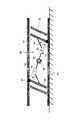
次に、図1及び図2には、本発明のいくつかの実施態様によるアンテナ10が図示されている。アンテナ10は、望ましくは整列して配置されたアクティブパネル14の上に配置される複数のアンテナ素子12を含む。アンテナ素子12は、アンテナ10が用いられる周波数領域での動作に使用できる任意の種類のアンテナ受信/送信ユニットから構成することができる。アンテナ素子12は、任意の所望の実質的に平面の形状、望ましくは直方平面をもつアクティブパネル14の上に配置される。アンテナ素子12は、アクティブパネル14の上に任意のパターンで配置される。任意のパターンには、例えば3×5、2×4、5×8配列などに限らず、例えば、円、楕円、あるいは擬似乱数パターンといった非直交パターン等も含まれる。1 and 2, an
望ましくはアンテナ素子12は、例えばアンテナ10が設計された信号波長(λ)の半分の直径の放射素子であり、上述のパターンの任意の一つのような直交パターンでアクティブパネル14上に配置されることが望ましい。Desirably, the
アンテナ素子12のアレイは、アンテナ素子12の各々の有効焦点方向17が図1に示す基準面11に対して実質的に入射角αをなす方向を向くように、アクティブパネル14上に配置され、電気的に相互に接続されている。図1及び図2に示すように、アンテナ素子12は、アクティブパネル14の平面に垂直で、アクティブパネル14の実質的に中心を通る直線17に実質的に並行な方向でコヒーレントに受信(又は送信)するように向けられる。素子12の各サブアレイは、従って基準面11に対して入射角αで到達する放射を受信する。送信の実施態様においては、素子12の各々は、基準面11に対する出射角αで放射を送信する。Array of
図1及び図2に示す実施態様では、アンテナ10は波長約24mmつまり2.4cm、即ち12.5GHzの信号を受信するように同調されている。アクティブパネル14の幅をdLと表記する。In the embodiment shown in FIGS. 1 and 2, the
図1及び図2において、隣接するアクティブパネル14の対応する点の間の水平距離は次式で与えられる。
D=dL/sin(α)
ここで、
α;アクティブパネル14の垂線17と基準面11とのなす角。通常は、基準面11はアンテナ10が取り付けられる移動プラットフォームの本体に平行となる。
dL;アクティブパネル14の幅1 and 2, the horizontal distance between corresponding points on adjacent
D = dL / sin (α)
here,
alpha; anglebetween the
dL ; width of the
アンテナ10の方向が放射の方向を正しく追跡しているときは、アクティブパネル14の垂線17と基準面11とのなす角αは、基準面11と放射源とがなす角αに実質的に等しくなる。When the direction of the
アンテナ10の中にあるn個のアクティブパネル14について、アンテナ10の全長D’は D’=(n−1)*D+dL*sin(α) から計算される。About the n
パネル間の距離Dは、入射角αからアンテナ10を見たときに、実質的にアクティブパネル14が、隣接するアクティブパネル14のどの部分をも部分的に又は完全に覆わないように決定される。更に、角度αから見ると、全てのアクティブパネル14が互いにほとんど境を接している(すなわち、切れ目無く、又は接触している)ように見える。傾斜角αの範囲に対して、アクティブパネル14の傾斜軸16は、全てのアクティブパネル14の傾斜軸16が実質的に互いに平行かつ支持機構に垂直のまま保たれるように、基準面11に平行な方向へスライド自在に支持機構に取り付けられてもよい。これにより、距離Dが調整される。この距離Dの制御は、上述したような、隣接するアクティブパネル14の外郭が重なり合わない状態が動作設計範囲内の全てのαの値に対して維持されるよう、受信/送信角αの適合を追跡することを目的としたものであってもよい。The distance Dbetween the panels when viewed
これまでに、ここに提示する原理に従って構成されたアンテナがサブアレイ面同士の部分的な重なりに起因するアンテナビームの利得損失を大きく低減することを明らかにした。更に、全てのアクティブパネル14が、入射角αでアンテナ10に当たる放射に対して完全に開放されているため、アンテナ10の全体にわたるアクティブパネルの開口全体、即ちアンテナの全有効開口寸法を大きくし、従ってアンテナ10は比較的高いアンテナ利得を有する。このため、アンテナ10は、例えば衛星通信用に、低エネルギー通信システムで使用することができる。また、前述の原理に従って構成されたアンテナは、有効な入射角に垂直な面へのアクティブパネルの投影の間に生じるギャップあるいは間隔を原因とする、いわゆるグレーティングローブ(grating lobe)を解消(又は大きく低減)する。So far, antenna constructed according to the principlespresented revealed togreatly reduce the loss of gain of the antenna beam due to the partial overlapping ofthe sub-array planehere. Additionally, all
基準面に垂直かつ実質的に基準面の中心で基準面11に交差する中心軸のまわりにアンテナを回転させることにより、アンテナ10の方位角を変えることができる点が注目される。同様にして、仰角の適切な設計範囲にわたって有効に切れ目の無い全開口範囲を維持するように間隔Dを調整しているときに、アクティブパネル14を同期して傾けることにより、アンテナ10の仰角αも変えることができる。アンテナ10の方位角θと仰角α、及び間隔Dは、例えば空気圧式直動アクチュエータ、電動式直動アクチュエータ、あるいは適当な伝動装置を備えたモータ等の適当な駆動アクチュエータを使用して、手動あるいは自動で設定される。Itis noted that the azimuth angle of the
アンテナ10は、アンテナ10を基準面11に垂直な軸の周りに回転させて任意の方位角に向けることを可能にする、回転可能な運搬プラットフォーム上に設置されてもよい。
移動する放射源/受信機と信号を受送信するために、あるいは、静止又は移動する放射源/受信機に対するアンテナの動きを説明するために、任意の適当な制御可能な駆動手段を使用して、アンテナ10のビームを方位角と仰角を(例えば、適切な設計範囲で)任意に組み合わせた方向に向けることができる。To be receiving and transmitting the radiation source / receiver and signal moving, or, in order to explain the movement of the antenna with respect to the radiation source / receiver for stationary or mobile,usingany suitable controllable drive means , a beam azimuth and elevation of the antenna 10(e.g., in an appropriate design range) can Kerutoward the direction in combination arbitrarily.
図3は、本発明の幾つかの実施態様により作られ、動作するアンテナ30を図示する。アンテナ30は有限個の(幅dLの)アクティブパネル34からなる。図3の例には2つのアクティブパネルがある。アクティブパネル34は、上述の動作原理に従って、傾斜軸32の周りに傾く。アンテナ30はまた、1つ以上の補助アクティブパネル35を含み、やはりその傾斜軸36の周りを傾き、基準面31に対する仰角αを定義する。仰角αがあらかじめ定めたより大きな仰角αの傾斜範囲内にあるときには、補助アクティブパネル35もアクティブパネル34の動作原理に従って傾斜する。この配置は、例えば、構造上の制約等によりアンテナ30の全長が制限され、そのためアクティブパネル34と隣接する補助アクティブパネル35との間隔が上述の傾斜角αの一定の範囲についての規定に必ずしも従うとは限らない場合に有用である。FIG. 3 illustrates an
望ましくは、アンテナ30の特定の用途に必要と認められる最大のビームステアリング範囲を提供するために駆動アクチュエータが使用されてもよい。駆動アクチュエータは、空気圧式直動アクチュエータ、電動式直動アクチュエータ、適当な伝動装置を備えたモータ、その他の適当な種類のものでよい。Desirably, a drive actuatormay be usedtoprovide the maximum beam steering range deemed necessary for aparticular application of the
明らかに、個々のアンテナに必要な最大ビームステアリングは、受信信号の入射角(受信アンテナの場合)あるいは受信機の位置(送信アンテナの場合)の予想される変化量、および、アンテナのサイズ又は開口の関数であるアンテナビームの幅によって決まる。開口が大きいほどビーム幅は狭くなる。Clearly, the maximum beam steering required for an individual antenna is the expected change in the angle of incidence of the received signal (for receive antennas) or receiver position (for transmit antennas), andthe size or aperture of the antenna. Is determined by the widthof the antenna beam asa function of The larger the aperture, the narrower the beam width.
次に、図4について説明する。この図は、本発明の幾つかの実施態様によるアンテナの構成と動作を示す線図であり、低姿勢アンテナ40が開示されている。アクチュエータ41、ガイドレール42、アンテナアクティブパネル43、補助アンテナアクティブパネル45、伸縮棒44、そしてスライド自在な支持手段47が用いられている。伸縮棒44とアンテナアクティブパネル43のなす角度は、所定の角度(図4の実施例では約90°)に固定される。アクチュエータ41が作動すると、伸縮棒44を共通の長手方向軸に沿って伸縮させ、2つのアクティブパネル43は実質的に互いに平行を保ち、従って角度αが変化する。同様に、アクチュエータ41は中心軸48の周囲を回転すると、アクティブパネル43を実質的に互いに平行に保ったまま角度αが変化するように、伸縮棒とガイドレール42のなす相対角度が変化する。Next, FIG. 4 will be described. This figure is a diagram showing the configuration and operation of an antenna according tosome embodiments of the present invention, in which a low-
我々のアンテナの一つの例示的な実施形態は、一つ以上のアクティブパネル上に配置された複数のアンテナと、支持フレームとを含み、アクティブパネルは各回転軸と平行に支持フレームに回転可能に接続されている。アクティブパネルはまた、前記回転軸と同一平面内に含まれる直線方向へ互いに対して並進移動可能である。アクティブパネルは通常は焦点を向くことが可能であり、アクティブパネルが所定の入射角を向くと、その角度から見ると前記アクティブパネルの各隣接する対は実質的に互いに境界をなす。すなわち、各入射角において、アクティブパネルの入射角に垂直な平面への投影が任意の2つの隣接するアクティブパネルの投影間に全く隙間を見せないようにパネルが動く。この実施例において、アクティブパネルはこの好ましい所定の角度を向き、そして全アンテナ利得はアクティブパネルの開口の全ての和と同等の開口をもつ単一のアンテナのアンテナ利得で近似される。 One exemplary embodiment of our antenna includes a plurality of antennas disposed on one or more active panels and a support frame, the active panel being rotatable to the support frame parallel to each axis of rotation. It is connected. The active panels can also be translated relative to each other in a linear direction contained within the same plane as the axis of rotation. The active panel is usually capable of focusing, and when the active panel is oriented at a predetermined angle of incidence, each adjacent pair of the active panel is substantially bounded by each other when viewed from that angle. That is, at each incident angle, the panel moves so that the projection onto the plane perpendicular to the incident angle of the active panel does not show any gap between the projections of any two adjacent active panels. In this embodiment, the active panel is oriented at this preferred predetermined angle, and the total antenna gain is approximated by the antenna gain of a single antenna having an aperture equal to the sum of all of the active panel apertures.
必要であれば、この実施形態は、入射角の限定された範囲に対してアクティブパネルと平行になるように、やはりその軸の周りに回転可能な少なくとも一つの副アクティブパネルを配置する。 If necessary, this embodiment places at least one secondary active panel that is also rotatable about its axis so that it is parallel to the active panel for a limited range of incident angles.
アクティブパネルのための支持フレームは、望ましくはアクティブパネルの回転軸を含む平面に垂直な軸の周りに回転可能である。アクティブパネルの回転はアクチュエータによって駆動される。前記方向付け可能なアクティブパネルの角度方向もアクチュエータによって駆動される。回転可能の支持フレームの回転もアクチュエータによって駆動される。アクチュエータは空気圧式直動アクチュエータ、電気式直道アクチュエータ、又は電気モータのうちの任意の一つであってもよい。 The support frame for the active panel is preferably rotatable about an axis perpendicular to the plane containing the axis of rotation of the active panel. The rotation of the active panel is driven by an actuator. The angular direction of the directable active panel is also driven by an actuator. The rotation of the rotatable support frame is also driven by the actuator. The actuator may be any one of a pneumatic linear actuator, an electric linear actuator, or an electric motor.
アンテナによる電気信号の受信又は送信のための方法の一つの例示的実施形態は、各々がアンテナ素子を備える複数のアンテナパネルを備えることと、アンテナパネルを回転可能に支持することと、アンテナパネルを送信機又は受信器に向けて共通の焦点に方向付けることとを含む。複数のアンテナパネルは、それらの回転軸に垂直な軸の周りに回転される。アクティブアンテナパネルは少なくとも一つのアクチュエータによって方向付けされ又は回転される。 One exemplary embodiment of a method for receiving or transmitting an electrical signal by an antenna includes a plurality of antenna panels, each comprising an antenna element, rotatably supporting the antenna panel, Directing to a common focus towards the transmitter or receiver. The plurality of antenna panels are rotated about an axis perpendicular to their rotation axis. The active antenna panel is directed or rotated by at least one actuator.
010、030 アンテナ
011、031 基準面
012 アンテナ素子
014、034、043 アクティブパネル
016、032 アクティブパネルの回転(傾斜)軸
017 アクティブパネルの垂線
035、045 補助アクティブパネル
036 補助アクティブパネルの回転(傾斜)軸
040 低姿勢アンテナ
041 アクチュエータ
042 ガイドレール
044 伸縮棒
047 スライド自在な支持手段
048 アクチュエータの回転中心軸010, 030 Antenna 011, 031 Reference plane 012 Antenna element 014, 034, 043 Active panel 016, 032 Active panel rotation (tilt) axis 017 Active panel perpendicular 035, 045 Auxiliary active panel 036 Rotation of auxiliary active panel (tilt) Axis 040 Low attitude antenna 041 Actuator 042 Guide rail 044 Telescopic rod 047 Sliding support means 048 Actuator rotation center axis
Claims (30)
Translated fromJapanese前記支持フレームに対して並進運動および回転運動が可能となるよう機械的に構成され、前記支持フレームに対してビーム方向が可変な複数のアンテナパネル(14)と、
前記アンテナパネルに連結された少なくとも一つのアクチュエータと、を備え、
前記少なくとも一つのアクチュエータは、
前記複数のアンテナパネルのビーム方向(17)を変えて送信機又は受信機を追尾するように、前記複数のアンテナパネルを、互いに実質的に平行に保ちつつ、前記支持フレームに支持された軸(16)周りに回転させ、
所定範囲のどのビーム方向(α)から見ても、前記複数のアンテナパネルのうち少なくとも二つの隣接するアンテナパネル同士が、ビーム方向(17)に垂直な平面上に投影した際、互いが実質的に接し、一のアンテナパネルが他のアンテナパネルによって部分的又は完全に覆われることがないように、前記少なくとも二つのアンテナパネルの前記軸(16)を基準面(11)に実質的に平行な方向へ動かすことにより、前記少なくとも2つの隣接するパネルの間の距離(D)を調整するよう構成されることを特徴とするアンテナ。A support frame;
A plurality of antenna panels (14) that are mechanically configured to be able to translate and rotate with respect to the support frame and have a variable beam direction with respect to the support frame;
And a least one actuatorcoupled to the antenna panel,
The at least one actuator comprises:
The shafts supported by the support frame while keeping the plurality of antenna panels substantially parallel to each other so as to track the transmitter or the receiver by changing the beam direction (17) of the plurality of antenna panels. 16) rotate around,
When viewed from any beam direction (α) within a predetermined range, when at least two adjacent antenna panels among the plurality of antenna panels are projected onto a plane perpendicular to the beam direction (17), they are substantially each other. The axis (16) of the at least two antenna panels is substantially parallel to the reference plane (11) so that one antenna panel is not partially or completely covered by another antenna panel. An antenna configured to adjust a distance (D) between the at least two adjacent panels by moving in a direction.
前記アンテナパネル(14)のビーム方向(17)を送信機又は受信機に向け、
送信機又は受信機を追尾しながら、共通のビーム方向を定義するアンテナパネルのビーム方向(17)を変化させ、
何れの組の隣接するアンテナパネル同士も、ビーム方向に垂直な平面上に投影した際に互いが実質的に接し、所定範囲のどのビーム方向から見ても、何れのアンテナパネルも他のアンテナパネルによって部分的又は完全に覆われることがないように、前記アンテナパネルを基準面(11)と実質的に平行な方向へ動かすことによって、ビーム方向に応じて前記アンテナパネル間の間隔(D)を変化させることを特徴とする方法。A support frame, a plurality of antenna panels (14) mechanically configured to be able to translate and rotate with respect to the support frame, the beam direction being variable with respect to the support frame; and the antenna panel It is a method for receiving or transmitting an electrical signal by an antenna (10) that is connected and has at least one actuator configured to track a transmitter or a receiver by changing the beam direction of the plurality of antenna panels. And
Directing the beam direction (17) of the antenna panel (14) to a transmitter or receiver;
While tracking the transmitter or receiver, change the beam direction (17) of the antenna panel that defines the common beam direction,
Any pair of adjacent antenna panels are substantially in contact with each other when projected onto a plane perpendicular to the beam direction, and any antenna panel is another antenna panel when viewed from any beam direction within a predetermined range. By moving the antenna panels in a direction substantially parallel to the reference plane (11) so that the distance (D) between the antenna panels depends on the beam direction. A method characterized by changing.
主ビーム方向(17)を有するRF放射パターンを定義するRFアンテナ素子(12)の副配列を搭載する複数のパネル(14)と、を備え、
前記各パネルは、実質的に平行な直線に沿った対応する副配列パターンのビームの仰角を角度制御するために、仰角駆動機構によって、互いに平行なそれぞれの第1の軸を中心に角運動可能に搭載され、
前記各パネルは、また、対応する副配列パターンのビームの方位角を角度制御するために、方位角駆動機構によって、前記第1の軸に実質的に垂直な共通の第2の軸を中心に回転可能に搭載され、
前記パネルの少なくとも一つは、また、直線並進駆動機構によって、前記第1の軸と第2の軸に実質的に垂直な直線軸に沿って、前記パネルのうち少なくも一つの他のパネルに対して、所定の距離(D)を規定するために基準面(11)と実質的に平行な方向に並進運動可能に搭載されており、
角度(α)の範囲に亘って、隣接する一対のパネルの各々は、アンテナのビーム方向(17)に垂直な平面上に投影された際、実質的に他方と接し、前記ビーム方向からいずれのパネルも完全にまたは部分的に覆われないことを特徴とするRFアンテナ配列。A support frame;
A plurality of panels (14) carrying a sub-array of RF antenna elements (12) defining an RF radiation pattern having a main beam direction (17);
Each of the panels can be angularly moved about respective first axes parallel to each other by an elevation driving mechanism in order to control the elevation of the beam of the corresponding sub-array pattern along a substantially parallel straight line. Mounted on
Each panel is also centered about a common second axis substantially perpendicular to the first axis by an azimuth angle drive mechanism to angle control the azimuth angle of the corresponding sub-array pattern beam. It is mounted rotatably
At least one of the panels is also connected to at least one other panel of the panels along a linear axis substantially perpendicular to the first and second axes by a linear translation drive mechanism. On the other hand, in order to define a predetermined distance (D), it is mounted so as to be able to translate in a direction substantially parallel to the reference plane (11),
Over a range of angles (α), each of a pair of adjacent panels is substantially in contact with the other when projected onto a plane perpendicular to the beam direction (17) of the antenna. An RF antenna arrangement characterized in that the panel is also not completely or partially covered.
前記独立に制御可能なパネルの少なくとも隣接する2つのパネルの間の距離(D)を決定し、
前記パネルの少なくとも一つと、前記パネルのうち少なくも一つの他のパネルとの間の距離が前記距離(D)となるように、前記パネルの少なくとも一つを、前記パネルのうち少なくも一つの他のパネルに対して、前記第1の軸と第2の軸に実質的に垂直な直線軸に沿って、角度制御された仰角に応じて、基準面に実質的に平行に並進運動させ、
角度(α)の範囲に亘って、隣接する一対のパネルの各々は、互いに前記アンテナのビーム方向(17)に垂直な平面上に投影された際、実質的に他方と接し、前記ビーム方向からいずれのパネルも完全にまたは部分的に覆われないことを特徴とするRFアンテナ配列を操作する方法。Corresponding RF antenna array with sub-arrays of RF antenna elements defining respective RF radiation patterns having a main beam direction on each of a plurality of independently controllable panels along substantially parallel straight lines In order to control the elevation angle of the beam of the sub-array pattern, the panels are angularly moved around the first axes parallel to each other, and the azimuth angle of the beam of the corresponding sub-array pattern is controlled. A method of manipulating each panel by angular motion about a common second axis substantially perpendicular to the first axis,
Determining a distance (D) between at least two adjacent panels of the independently controllable panels;
At least one of the panels is at least one of the panels so that a distance between at least one of the panels and at least one other panel of the panels is the distance (D). Translate the other panel substantially parallel to the reference plane along a linear axis substantially perpendicular to the first axis and the second axis, depending on the angle-controlled elevation angle;
Over a range of angles (α), each of a pair of adjacent panels is substantially in contact with the other when projected onto a plane perpendicular to the beam direction (17) of the antenna, and from the beam direction. A method of operating an RF antenna array, characterized in that none of the panels are completely or partially covered.
前記パネルが、隣接する副配列の互いに平行なそれぞれの主ビーム方向に沿った投影が、ある範囲の仰角に亘って、実質的な間隙も実質的な重なりもなく概ね接するように、パネル間隔の並進運動を協調して行うように搭載されていることを特徴とするRFアンテナ配列。Each panel (14) includes a sub-array of RF antenna elements (12) defining an RF radiation pattern having a main beam direction, and each panel (14) has a main beam direction (17) parallel to each other. An RF antenna array mounted to coordinate movement at elevation and movement at azimuth to track an RF object at elevation (α) and azimuth while maintaining
The panel spacing is such that the projections along each parallel main beam direction of adjacent sub-arrays are generally in contact with each other over a range of elevation angles without substantial gaps or substantial overlap. An RF antenna array, which is mounted so as to coordinately perform translational motion.
前記パネルが、隣接する副配列の互いに平行なそれぞれの主ビーム方向(17)に沿った投影が、ある範囲の仰角に亘って、実質的な間隙も実質的な重なりもなく概ね接するように、互いに平行な主ビーム方向を前記副配列に対して維持しながら、仰角と方位角においてRF対象を追尾するために、仰角、方位角、およびパネル間隔における協調動作を制御することを特徴とするRFアンテナ配列を操作する方法。A method of operating an RF antenna array, wherein a sub-array (14) of RF antenna elements (12) defining an RF radiation pattern having a main beam direction is arranged on each of a plurality of panels,
So that the projections along the respective parallel main beam directions (17) of adjacent sub-arrays are generally in contact with each other over a range of elevation angles without substantial gaps or substantial overlap. Controlling coordinated operations in elevation, azimuth, and panel spacing to track RF objects at elevation and azimuth while maintaining mutually parallel main beam directions relative to the sub-array How to manipulate the antenna array.
Applications Claiming Priority (3)
| Application Number | Priority Date | Filing Date | Title |
|---|---|---|---|
| IL154525 | 2003-02-18 | ||
| IL154525AIL154525A (en) | 2003-02-18 | 2003-02-18 | Low profile antenna for satellite communication |
| PCT/IL2004/000149WO2004075339A2 (en) | 2003-02-18 | 2004-02-18 | Low profile antenna for satellite communication |
Publications (3)
| Publication Number | Publication Date |
|---|---|
| JP2006518145A JP2006518145A (en) | 2006-08-03 |
| JP2006518145A5 JP2006518145A5 (en) | 2007-06-21 |
| JP4740109B2true JP4740109B2 (en) | 2011-08-03 |
Family
ID=32894017
Family Applications (1)
| Application Number | Title | Priority Date | Filing Date |
|---|---|---|---|
| JP2006502642AExpired - LifetimeJP4740109B2 (en) | 2003-02-18 | 2004-02-18 | Low profile antenna for satellite communications |
Country Status (8)
| Country | Link |
|---|---|
| US (3) | US7629935B2 (en) |
| EP (1) | EP1604427B1 (en) |
| JP (1) | JP4740109B2 (en) |
| AT (1) | ATE457087T1 (en) |
| DE (1) | DE602004025412D1 (en) |
| ES (1) | ES2339449T3 (en) |
| IL (1) | IL154525A (en) |
| WO (1) | WO2004075339A2 (en) |
Families Citing this family (41)
| Publication number | Priority date | Publication date | Assignee | Title |
|---|---|---|---|---|
| US7379707B2 (en)* | 2004-08-26 | 2008-05-27 | Raysat Antenna Systems, L.L.C. | System for concurrent mobile two-way data communications and TV reception |
| US7705793B2 (en) | 2004-06-10 | 2010-04-27 | Raysat Antenna Systems | Applications for low profile two way satellite antenna system |
| IL154525A (en) | 2003-02-18 | 2011-07-31 | Starling Advanced Comm Ltd | Low profile antenna for satellite communication |
| US6999036B2 (en)* | 2004-01-07 | 2006-02-14 | Raysat Cyprus Limited | Mobile antenna system for satellite communications |
| US20110215985A1 (en)* | 2004-06-10 | 2011-09-08 | Raysat Antenna Systems, L.L.C. | Applications for Low Profile Two Way Satellite Antenna System |
| US8761663B2 (en)* | 2004-01-07 | 2014-06-24 | Gilat Satellite Networks, Ltd | Antenna system |
| US7911400B2 (en) | 2004-01-07 | 2011-03-22 | Raysat Antenna Systems, L.L.C. | Applications for low profile two-way satellite antenna system |
| US7109937B2 (en) | 2004-11-29 | 2006-09-19 | Elta Systems Ltd. | Phased array planar antenna and a method thereof |
| US7061432B1 (en) | 2005-06-10 | 2006-06-13 | X-Ether, Inc. | Compact and low profile satellite communication antenna system |
| IL171450A (en)* | 2005-10-16 | 2011-03-31 | Starling Advanced Comm Ltd | Antenna panel |
| IL174549A (en) | 2005-10-16 | 2010-12-30 | Starling Advanced Comm Ltd | Dual polarization planar array antenna and cell elements therefor |
| FR2911011B1 (en)* | 2006-12-27 | 2010-08-27 | Alcatel Lucent | RECONFIGURABLE RADIANT ARRAY ANTENNA |
| US7990329B2 (en)* | 2007-03-08 | 2011-08-02 | Powerwave Technologies Inc. | Dual staggered vertically polarized variable azimuth beamwidth antenna for wireless network |
| TWI396817B (en)* | 2007-09-20 | 2013-05-21 | Asustek Comp Inc | Air conditioner |
| EP2232632B1 (en)* | 2007-11-28 | 2017-03-01 | Intel Corporation | Linear antenna array with azimuth beam augmentation by axial rotation |
| US20090278762A1 (en)* | 2008-05-09 | 2009-11-12 | Viasat, Inc. | Antenna Modular Sub-array Super Component |
| US8120537B2 (en)* | 2008-05-09 | 2012-02-21 | Viasat, Inc. | Inclined antenna systems and methods |
| US8711048B2 (en) | 2010-06-01 | 2014-04-29 | Syntonics, Llc | Damage resistant antenna |
| US8289221B1 (en)* | 2010-06-28 | 2012-10-16 | The United States Of America As Represented By The Secretary Of The Air Force | Deployable reflectarray antenna system |
| US8362969B2 (en)* | 2010-08-30 | 2013-01-29 | Arc Wireless Solutions, Inc. | Adjustable antenna baffling system |
| US8810464B2 (en)* | 2011-05-11 | 2014-08-19 | Anderson Aerospace | Compact high efficiency intregrated direct wave mobile communications terminal |
| TW201328028A (en)* | 2011-12-30 | 2013-07-01 | Gemintek Corp | Multipoint drive device for all-purpose base station antenna |
| US8773319B1 (en) | 2012-01-30 | 2014-07-08 | L-3 Communications Corp. | Conformal lens-reflector antenna system |
| US20140090004A1 (en)* | 2012-09-25 | 2014-03-27 | Aereo, Inc. | Antenna System and Installation for High Volume Television Capture |
| CA2831325A1 (en) | 2012-12-18 | 2014-06-18 | Panasonic Avionics Corporation | Antenna system calibration |
| CA2838861A1 (en) | 2013-02-12 | 2014-08-12 | Panasonic Avionics Corporation | Optimization of low profile antenna(s) for equatorial operation |
| KR20140109712A (en)* | 2013-03-06 | 2014-09-16 | 주식회사 케이엠더블유 | Horizontal array with the antenna radiating elements |
| EP3161902B1 (en)* | 2014-06-27 | 2020-03-18 | ViaSat, Inc. | System and apparatus for driving antenna |
| US11183749B2 (en) | 2015-06-05 | 2021-11-23 | Viasat, Inc. | Methods and systems for mitigating interference with a nearby satellite |
| US10135126B2 (en) | 2015-06-05 | 2018-11-20 | Viasat, Inc. | Methods and systems for mitigating interference with a nearby satellite |
| US9577723B1 (en)* | 2015-08-10 | 2017-02-21 | The Boeing Company | Systems and methods of analog beamforming for direct radiating phased array antennas |
| US10418716B2 (en)* | 2015-08-27 | 2019-09-17 | Commscope Technologies Llc | Lensed antennas for use in cellular and other communications systems |
| JP6095022B1 (en)* | 2015-12-04 | 2017-03-15 | 三菱電機株式会社 | Wave energy radiation device |
| US9485009B1 (en) | 2016-04-13 | 2016-11-01 | Panasonic Avionics Corporation | Antenna system with high dynamic range amplifier for receive antenna elements |
| CN106129624A (en)* | 2016-08-16 | 2016-11-16 | 钟彦珽 | Antenna direction adjusts system |
| US10277308B1 (en) | 2016-09-22 | 2019-04-30 | Viasat, Inc. | Methods and systems of adaptive antenna pointing for mitigating interference with a nearby satellite |
| WO2019222858A1 (en) | 2018-05-24 | 2019-11-28 | Nanowave Technologies Inc. | System and method for improved radar sensitivity |
| WO2019222859A1 (en)* | 2018-05-24 | 2019-11-28 | Nanowave Technologies Inc. | Radar antenna system and method |
| CN109560862A (en)* | 2019-01-23 | 2019-04-02 | 长沙天仪空间科技研究院有限公司 | A kind of Inter-satellite Communication System and method based on Satellite Formation Flying |
| UA125954C2 (en)* | 2020-12-09 | 2022-07-13 | Національний Технічний Університет України "Київський Політехнічний Інститут Імені Ігоря Сікорського" | Housing of a transceiver module of an antenna array |
| US12341250B1 (en) | 2022-12-12 | 2025-06-24 | National Technology & Engineering Solutions Of Sandia, Llc | Offset-fed reflector parallel plate antenna apparatus |
Family Cites Families (136)
| Publication number | Priority date | Publication date | Assignee | Title |
|---|---|---|---|---|
| US3810185A (en) | 1972-05-26 | 1974-05-07 | Communications Satellite Corp | Dual polarized cylindrical reflector antenna system |
| US4263598A (en) | 1978-11-22 | 1981-04-21 | Motorola, Inc. | Dual polarized image antenna |
| US5258250A (en) | 1981-01-16 | 1993-11-02 | Canon Kabushiki Kaisha | Photoconductive member |
| FR2505097A1 (en) | 1981-05-04 | 1982-11-05 | Labo Electronique Physique | RADIATION ELEMENT OR CIRCULAR POLARIZATION HYPERFREQUENCY SIGNAL RECEIVER AND MICROWAVE PLANE ANTENNA COMPRISING A NETWORK OF SUCH ELEMENTS |
| FR2523376A1 (en) | 1982-03-12 | 1983-09-16 | Labo Electronique Physique | RADIATION ELEMENT OR HYPERFREQUENCY SIGNAL RECEIVER WITH LEFT AND RIGHT CIRCULAR POLARIZATIONS AND FLAT ANTENNA COMPRISING A NETWORK OF SUCH JUXTAPOSED ELEMENTS |
| FR2544920B1 (en) | 1983-04-22 | 1985-06-14 | Labo Electronique Physique | MICROWAVE PLANAR ANTENNA WITH A FULLY SUSPENDED SUBSTRATE LINE ARRAY |
| US4647938A (en) | 1984-10-29 | 1987-03-03 | Agence Spatiale Europeenne | Double grid reflector antenna |
| GB2166600B (en) | 1984-11-01 | 1988-12-29 | Matsushita Electric Works Ltd | Microwave plane antenna |
| US4801943A (en) | 1986-01-27 | 1989-01-31 | Matsushita Electric Works, Ltd. | Plane antenna assembly |
| JPS62173807A (en)* | 1986-01-27 | 1987-07-30 | Mitsubishi Electric Corp | Constant current source bias circuit |
| US5508731A (en) | 1986-03-10 | 1996-04-16 | Response Reward Systems L.C. | Generation of enlarged participatory broadcast audience |
| JPS62173807U (en) | 1986-04-24 | 1987-11-05 | ||
| JPS63174411U (en) | 1986-12-12 | 1988-11-11 | ||
| JPS63108805U (en) | 1987-01-06 | 1988-07-13 | ||
| AU3417289A (en) | 1988-03-30 | 1989-10-16 | British Satellite Broadcasting Limited | Flat plate array antenna |
| AU622444B2 (en) | 1988-04-12 | 1992-04-09 | Nemoto Project Industry Co., Ltd. | Antenna apparatus and attitude control method |
| JPH02137402A (en) | 1988-11-18 | 1990-05-25 | Nec Home Electron Ltd | Beam tilt type flat array antenna |
| JPH03247003A (en) | 1990-02-23 | 1991-11-05 | Matsushita Electric Works Ltd | Automatic tracking antenna system for satellite broadcast receiver |
| FR2668305B1 (en) | 1990-10-18 | 1992-12-04 | Alcatel Espace | DEVICE FOR SUPPLYING A RADIANT ELEMENT OPERATING IN DOUBLE POLARIZATION. |
| JP3032310B2 (en) | 1991-02-28 | 2000-04-17 | 株式会社豊田中央研究所 | Tracking antenna device |
| US5137443A (en) | 1991-05-10 | 1992-08-11 | Husky Injection Molding Systems Ltd. | Apparatus for forming hollow plastic article |
| FR2677491B1 (en) | 1991-06-10 | 1993-08-20 | Alcatel Espace | BIPOLARIZED ELEMENTARY HYPERFREQUENCY ANTENNA. |
| JP2626686B2 (en) | 1991-06-26 | 1997-07-02 | 新日本製鐵株式会社 | Mobile antenna device |
| US5740035A (en) | 1991-07-23 | 1998-04-14 | Control Data Corporation | Self-administered survey systems, methods and devices |
| US5861881A (en) | 1991-11-25 | 1999-01-19 | Actv, Inc. | Interactive computer system for providing an interactive presentation with personalized video, audio and graphics responses for multiple viewers |
| JP2594483B2 (en) | 1991-12-10 | 1997-03-26 | 新日本製鐵株式会社 | Automatic tracking satellite broadcast receiving antenna device |
| US5389941A (en) | 1992-02-28 | 1995-02-14 | Hughes Aircraft Company | Data link antenna system |
| US5404509A (en) | 1992-05-08 | 1995-04-04 | Klein; Laurence C. | Conducting and managing sampled information audits for the determination of database accuracy |
| JPH06326510A (en) | 1992-11-18 | 1994-11-25 | Toshiba Corp | Beam scanning antenna and array antenna |
| US5528250A (en) | 1992-11-18 | 1996-06-18 | Winegard Company | Deployable satellite antenna for use on vehicles |
| DE69324771T2 (en) | 1992-11-30 | 1999-09-09 | All Nippon Airways Co. Ltd. | Mobile receiver for satellite radio |
| US5398035A (en) | 1992-11-30 | 1995-03-14 | The United States Of America As Represented By The Administrator Of The National Aeronautics And Space Administration | Satellite-tracking millimeter-wave reflector antenna system for mobile satellite-tracking |
| JPH06237113A (en)* | 1993-02-12 | 1994-08-23 | Aisin Seiki Co Ltd | Attitude controller for plural reception antennas |
| US6249809B1 (en) | 1993-08-30 | 2001-06-19 | William L. Bro | Automated and interactive telecommunications system |
| US5689641A (en) | 1993-10-01 | 1997-11-18 | Vicor, Inc. | Multimedia collaboration system arrangement for routing compressed AV signal through a participant site without decompressing the AV signal |
| JPH07106847A (en) | 1993-10-07 | 1995-04-21 | Nippon Steel Corp | Leaky Waveguide Slot Array Antenna |
| US5799151A (en) | 1994-04-04 | 1998-08-25 | Hoffer; Steven M. | Interactive electronic trade network and user interface |
| US5537141A (en) | 1994-04-15 | 1996-07-16 | Actv, Inc. | Distance learning system providing individual television participation, audio responses and memory for every student |
| US5544299A (en) | 1994-05-02 | 1996-08-06 | Wenstrand; John S. | Method for focus group control in a graphical user interface |
| JP2920160B2 (en) | 1994-06-29 | 1999-07-19 | ザ ウィタカー コーポレーション | Flat plate type microwave antenna for vehicle collision avoidance radar system |
| US5512906A (en)* | 1994-09-12 | 1996-04-30 | Speciale; Ross A. | Clustered phased array antenna |
| US5767897A (en) | 1994-10-31 | 1998-06-16 | Picturetel Corporation | Video conferencing system |
| US5844979A (en) | 1995-02-16 | 1998-12-01 | Global Technologies, Inc. | Intelligent switching system for voice and data |
| JPH08264500A (en)* | 1995-03-27 | 1996-10-11 | Sony Corp | Cleaning of substrate |
| JP3149156B2 (en) | 1995-05-25 | 2001-03-26 | アルプス電気株式会社 | Microwave antenna device for mounting on moving object |
| US5596336A (en) | 1995-06-07 | 1997-01-21 | Trw Inc. | Low profile TEM mode slot array antenna |
| GB2304208B (en) | 1995-08-07 | 1999-06-23 | Baylis Generators Ltd | Generator |
| US5764199A (en) | 1995-08-28 | 1998-06-09 | Datron/Transco, Inc. | Low profile semi-cylindrical lens antenna on a ground plane |
| US5781163A (en) | 1995-08-28 | 1998-07-14 | Datron/Transco, Inc. | Low profile hemispherical lens antenna array on a ground plane |
| US5823788A (en) | 1995-11-13 | 1998-10-20 | Lemelson; Jerome H. | Interactive educational system and method |
| US5801754A (en) | 1995-11-16 | 1998-09-01 | United Artists Theatre Circuit, Inc. | Interactive theater network system |
| US5880731A (en) | 1995-12-14 | 1999-03-09 | Microsoft Corporation | Use of avatars with automatic gesturing and bounded interaction in on-line chat session |
| US5886671A (en) | 1995-12-21 | 1999-03-23 | The Boeing Company | Low-cost communication phased-array antenna |
| FR2743199B1 (en) | 1996-01-03 | 1998-02-27 | Europ Agence Spatiale | RECEIVE AND / OR TRANSMITTER FLAT MICROWAVE NETWORK ANTENNA AND ITS APPLICATION TO THE RECEPTION OF GEOSTATIONARY TELEVISION SATELLITES |
| US6049306A (en) | 1996-01-04 | 2000-04-11 | Amarillas; Sal | Satellite antenna aiming device featuring real time elevation and heading adjustment |
| JP3363022B2 (en) | 1996-03-07 | 2003-01-07 | ケイディーディーアイ株式会社 | Fixed earth station |
| US5841980A (en) | 1996-05-15 | 1998-11-24 | Rtime, Inc. | Distributed system for communication networks in multi-user applications |
| US6259415B1 (en) | 1996-06-03 | 2001-07-10 | Bae Systems Advanced Systems | Minimum protrusion mechanically beam steered aircraft array antenna systems |
| US5995951A (en) | 1996-06-04 | 1999-11-30 | Recipio | Network collaboration method and apparatus |
| US5828839A (en) | 1996-11-14 | 1998-10-27 | Interactive Broadcaster Services Corp. | Computer network chat room based on channel broadcast in real time |
| US5916302A (en) | 1996-12-06 | 1999-06-29 | International Business Machines Corporation | Multimedia conferencing using parallel networks |
| US5929819A (en) | 1996-12-17 | 1999-07-27 | Hughes Electronics Corporation | Flat antenna for satellite communication |
| US6297774B1 (en) | 1997-03-12 | 2001-10-02 | Hsin- Hsien Chung | Low cost high performance portable phased array antenna system for satellite communication |
| US5991595A (en) | 1997-03-21 | 1999-11-23 | Educational Testing Service | Computerized system for scoring constructed responses and methods for training, monitoring, and evaluating human rater's scoring of constructed responses |
| ID24651A (en) | 1997-04-30 | 2000-07-27 | Cit Alcatel | A SYSTEM MAINLY DIRECTING ON NON-GEOSTASIONARY SATELLITIES |
| US6331837B1 (en) | 1997-05-23 | 2001-12-18 | Genghiscomm Llc | Spatial interferometry multiplexing in wireless communications |
| US6064978A (en) | 1997-06-24 | 2000-05-16 | Experts Exchange, Inc. | Question and answer system using computer networks |
| US5878214A (en) | 1997-07-10 | 1999-03-02 | Synectics Corporation | Computer-based group problem solving method and system |
| US5983071A (en) | 1997-07-22 | 1999-11-09 | Hughes Electronics Corporation | Video receiver with automatic satellite antenna orientation |
| KR100260417B1 (en) | 1997-08-28 | 2000-07-01 | 윤종용 | Method and system for surveying program pating using internet television |
| US5961092A (en) | 1997-08-28 | 1999-10-05 | Satellite Mobile Systems, Inc. | Vehicle with a satellite dish mounting mechanism for deployably mounting a satellite dish to the vehicle and method for deployably mounting a satellite dish to a vehicle |
| US5982333A (en) | 1997-09-03 | 1999-11-09 | Qualcomm Incorporated | Steerable antenna system |
| US6120534A (en) | 1997-10-29 | 2000-09-19 | Ruiz; Carlos E. | Endoluminal prosthesis having adjustable constriction |
| KR100287059B1 (en) | 1997-12-24 | 2001-04-16 | 정선종 | Structure of mobile active antenna system and satellite tracking method using the same |
| US6160520A (en) | 1998-01-08 | 2000-12-12 | E★Star, Inc. | Distributed bifocal abbe-sine for wide-angle multi-beam and scanning antenna system |
| US6078948A (en) | 1998-02-03 | 2000-06-20 | Syracuse University | Platform-independent collaboration backbone and framework for forming virtual communities having virtual rooms with collaborative sessions |
| US6993495B2 (en) | 1998-03-02 | 2006-01-31 | Insightexpress, L.L.C. | Dynamically assigning a survey to a respondent |
| US6074216A (en) | 1998-07-07 | 2000-06-13 | Hewlett-Packard Company | Intelligent interactive broadcast education |
| US5999208A (en) | 1998-07-15 | 1999-12-07 | Lucent Technologies Inc. | System for implementing multiple simultaneous meetings in a virtual reality mixed media meeting room |
| US6347333B2 (en) | 1999-01-15 | 2002-02-12 | Unext.Com Llc | Online virtual campus |
| US6256663B1 (en) | 1999-01-22 | 2001-07-03 | Greenfield Online, Inc. | System and method for conducting focus groups using remotely loaded participants over a computer network |
| US6204823B1 (en) | 1999-03-09 | 2001-03-20 | Harris Corporation | Low profile antenna positioner for adjusting elevation and azimuth |
| US6195060B1 (en)* | 1999-03-09 | 2001-02-27 | Harris Corporation | Antenna positioner control system |
| KR100309682B1 (en) | 1999-03-18 | 2001-09-26 | 오길록 | Satellite Tracking Control Method and Tracking apparatus for Vehicle-mounted Receive Antenna Systems |
| US6442590B1 (en) | 1999-05-27 | 2002-08-27 | Yodlee.Com, Inc. | Method and apparatus for a site-sensitive interactive chat network |
| WO2000075829A1 (en) | 1999-06-03 | 2000-12-14 | The Voice.Com, Inc. | System and method for creating, completing, processing and storing surveys and the results thereof over a network |
| US6578025B1 (en) | 1999-06-11 | 2003-06-10 | Abuzz Technologies, Inc. | Method and apparatus for distributing information to users |
| WO2001011718A1 (en)* | 1999-08-05 | 2001-02-15 | Sarnoff Corporation | Low profile steerable antenna |
| US6169522B1 (en) | 1999-09-03 | 2001-01-02 | Motorola, Inc. | Combined mechanical scanning and digital beamforming antenna |
| US6483472B2 (en) | 2000-01-11 | 2002-11-19 | Datron/Transo, Inc. | Multiple array antenna system |
| US6792448B1 (en) | 2000-01-14 | 2004-09-14 | Microsoft Corp. | Threaded text discussion system |
| US6710749B2 (en) | 2000-03-15 | 2004-03-23 | King Controls | Satellite locator system |
| EP1148583A1 (en) | 2000-04-18 | 2001-10-24 | Era Patents Limited | Planar array antenna |
| WO2001084266A2 (en) | 2000-05-01 | 2001-11-08 | Netoncourse, Inc. | Large group interactions via mass communication network |
| JP4198867B2 (en) | 2000-06-23 | 2008-12-17 | 株式会社東芝 | Antenna device |
| WO2002019232A1 (en) | 2000-09-01 | 2002-03-07 | Blue Bear Llc | System and method for performing market research studies on online content |
| JP2002111359A (en) | 2000-09-27 | 2002-04-12 | Murata Mfg Co Ltd | Antenna device, communication device and radar device |
| US7177851B2 (en) | 2000-11-10 | 2007-02-13 | Affinnova, Inc. | Method and apparatus for dynamic, real-time market segmentation |
| US6707432B2 (en) | 2000-12-21 | 2004-03-16 | Ems Technologies Canada Ltd. | Polarization control of parabolic antennas |
| US6677908B2 (en) | 2000-12-21 | 2004-01-13 | Ems Technologies Canada, Ltd | Multimedia aircraft antenna |
| GB0113296D0 (en)* | 2001-06-01 | 2001-07-25 | Fortel Technologies Inc | Microwave antennas |
| BG64659B1 (en) | 2001-06-14 | 2005-10-31 | Skygate International Technology N.V. | Method for scanning an antenna array and phase-adjustment device for the materialization thereof |
| US20020194054A1 (en) | 2001-06-18 | 2002-12-19 | Renee Frengut | Internet based qualitative research method and system |
| US6738024B2 (en) | 2001-06-22 | 2004-05-18 | Ems Technologies Canada, Ltd. | Mechanism for differential dual-directional antenna array |
| US6407714B1 (en) | 2001-06-22 | 2002-06-18 | Ems Technologies Canada, Ltd. | Mechanism for differential dual-directional antenna array |
| DE60113671T2 (en) | 2001-07-20 | 2006-07-06 | Eutelsat Sa | High-power and low-cost transceiver satellite antenna |
| US6624787B2 (en)* | 2001-10-01 | 2003-09-23 | Raytheon Company | Slot coupled, polarized, egg-crate radiator |
| US6496158B1 (en) | 2001-10-01 | 2002-12-17 | The Aerospace Corporation | Intermodulation grating lobe suppression method |
| US6657589B2 (en) | 2001-11-01 | 2003-12-02 | Tia, Mobile Inc. | Easy set-up, low profile, vehicle mounted, in-motion tracking, satellite antenna |
| ATE403949T1 (en) | 2001-11-09 | 2008-08-15 | Ems Technologies Inc | ANTENNA ARRAY FOR MOVING VEHICLES |
| US6861997B2 (en) | 2001-12-14 | 2005-03-01 | John P. Mahon | Parallel plate septum polarizer for low profile antenna applications |
| BG64431B1 (en) | 2001-12-19 | 2005-01-31 | Skygate International Technology N.V. | Antenna element |
| US6694137B2 (en) | 2002-04-29 | 2004-02-17 | Etherware, Llc | Method and system for providing broadband mobile access from geostationary satellites to platforms using small, low profile antennas |
| US6661388B2 (en) | 2002-05-10 | 2003-12-09 | The Boeing Company | Four element array of cassegrain reflector antennas |
| US6778144B2 (en) | 2002-07-02 | 2004-08-17 | Raytheon Company | Antenna |
| JP2004056643A (en)* | 2002-07-23 | 2004-02-19 | Communication Research Laboratory | Antenna device |
| US6765542B2 (en) | 2002-09-23 | 2004-07-20 | Andrew Corporation | Multiband antenna |
| US6746967B2 (en)* | 2002-09-30 | 2004-06-08 | Intel Corporation | Etching metal using sonication |
| US6827326B2 (en)* | 2002-10-23 | 2004-12-07 | Gci Pipe Products, Inc. | Modular forming system for box culvert |
| EP1565831A4 (en) | 2002-11-07 | 2009-08-26 | Invoke Solutions Inc | Survey system |
| IL154525A (en) | 2003-02-18 | 2011-07-31 | Starling Advanced Comm Ltd | Low profile antenna for satellite communication |
| BG107620A (en) | 2003-03-06 | 2004-09-30 | Raysat Cyprus Limited | Flat mobile aerial system |
| BG107622A (en) | 2003-03-07 | 2004-09-30 | Raysat Cyprus Limited | Following system for flat mobile aerial system |
| BG107771A (en) | 2003-04-30 | 2004-10-29 | Raysat Cyprus Limited | Adjustable phase shifter |
| US7084836B2 (en) | 2003-05-15 | 2006-08-01 | Espenscheid Mark W | Flat panel antenna array |
| BG107973A (en) | 2003-07-07 | 2005-01-31 | Raysat Cyprus Limited | Flat microwave antenna |
| US6864837B2 (en) | 2003-07-18 | 2005-03-08 | Ems Technologies, Inc. | Vertical electrical downtilt antenna |
| US6873301B1 (en) | 2003-10-07 | 2005-03-29 | Bae Systems Information And Electronic Systems Integration Inc. | Diamond array low-sidelobes flat-plate antenna systems for satellite communication |
| DE10356395A1 (en)* | 2003-12-03 | 2005-09-15 | Eads Deutschland Gmbh | Exterior structure-compliant antenna in a support structure of a vehicle |
| US6999036B2 (en) | 2004-01-07 | 2006-02-14 | Raysat Cyprus Limited | Mobile antenna system for satellite communications |
| US7177000B2 (en) | 2004-05-18 | 2007-02-13 | Automotive Systems Laboratory, Inc. | Liquid crystal display cell structure and manufacture process of a liquid crystal display comprising an opening formed through the color filter and partially the buffer layer |
| KR100656785B1 (en)* | 2004-12-21 | 2006-12-12 | 한국전자통신연구원 | Multiple Satellite Access Antenna System |
| US7061432B1 (en)* | 2005-06-10 | 2006-06-13 | X-Ether, Inc. | Compact and low profile satellite communication antenna system |
| IL174549A (en) | 2005-10-16 | 2010-12-30 | Starling Advanced Comm Ltd | Dual polarization planar array antenna and cell elements therefor |
| IL171450A (en) | 2005-10-16 | 2011-03-31 | Starling Advanced Comm Ltd | Antenna panel |
| US7382329B2 (en)* | 2006-05-11 | 2008-06-03 | Duk Yong Kim | Variable beam controlling antenna for a mobile communication base station |
- 2003
- 2003-02-18ILIL154525Apatent/IL154525A/enactiveIP Right Grant
- 2004
- 2004-02-18WOPCT/IL2004/000149patent/WO2004075339A2/enactiveSearch and Examination
- 2004-02-18DEDE602004025412Tpatent/DE602004025412D1/ennot_activeExpired - Lifetime
- 2004-02-18ATAT04712141Tpatent/ATE457087T1/ennot_activeIP Right Cessation
- 2004-02-18USUS10/546,264patent/US7629935B2/enactiveActive
- 2004-02-18EPEP04712141Apatent/EP1604427B1/ennot_activeExpired - Lifetime
- 2004-02-18ESES04712141Tpatent/ES2339449T3/ennot_activeExpired - Lifetime
- 2004-02-18JPJP2006502642Apatent/JP4740109B2/ennot_activeExpired - Lifetime
- 2006
- 2006-06-30USUS11/477,600patent/US7768469B2/enactiveActive
- 2009
- 2009-08-05USUS12/461,239patent/US7999750B2/ennot_activeExpired - Lifetime
Also Published As
| Publication number | Publication date |
|---|---|
| IL154525A (en) | 2011-07-31 |
| US7768469B2 (en) | 2010-08-03 |
| EP1604427A4 (en) | 2006-02-15 |
| JP2006518145A (en) | 2006-08-03 |
| US20060197713A1 (en) | 2006-09-07 |
| US7999750B2 (en) | 2011-08-16 |
| US20090295656A1 (en) | 2009-12-03 |
| DE602004025412D1 (en) | 2010-03-25 |
| WO2004075339A3 (en) | 2004-11-25 |
| ES2339449T3 (en) | 2010-05-20 |
| EP1604427B1 (en) | 2010-02-03 |
| US20060244669A1 (en) | 2006-11-02 |
| WO2004075339A2 (en) | 2004-09-02 |
| EP1604427A2 (en) | 2005-12-14 |
| ATE457087T1 (en) | 2010-02-15 |
| US7629935B2 (en) | 2009-12-08 |
Similar Documents
| Publication | Publication Date | Title |
|---|---|---|
| JP4740109B2 (en) | Low profile antenna for satellite communications | |
| JP2006518145A5 (en) | ||
| US10903565B2 (en) | Architectures and methods for novel antenna radiation optimization via feed repositioning | |
| JP4203225B2 (en) | Terminal antenna for communication system | |
| US6388634B1 (en) | Multi-beam antenna communication system and method | |
| US7388551B2 (en) | Antenna system | |
| US11451944B2 (en) | In-vehicle communication system | |
| EP1494313A1 (en) | Antenna system comprising a coverage antenna and an auxiliary antenna | |
| EP3248242B1 (en) | Multiple-feed antenna system having multi-position subreflector assembly | |
| KR20070091177A (en) | Phased array planar antenna and tracking method for tracking moving targets | |
| US7411561B1 (en) | Gimbaled dragonian antenna | |
| US20240275074A1 (en) | Active redirection devices for wireless applications | |
| EP2880713B1 (en) | Low cost, high-performance, switched multi-feed steerable antenna system | |
| KR102153441B1 (en) | Tracking antenna system having multiband selectable feed | |
| US20210313687A1 (en) | Radio transceiver with antenna array formed by horn-antenna elements | |
| US11831346B2 (en) | Adaptable, reconfigurable mobile very small aperture (VSAT) satellite communication terminal using an electronically scanned array (ESA) | |
| US7015866B1 (en) | Flush-mounted air vehicle array antenna systems for satellite communication | |
| IL201137A (en) | Low profile antenna for satellite communication | |
| JPH0556695B2 (en) | ||
| JP2021010145A (en) | Antenna device | |
| HK1231257B (en) | Tracking antenna system having multiband selectable feed | |
| HK1231257A1 (en) | Tracking antenna system having multiband selectable feed |
Legal Events
| Date | Code | Title | Description |
|---|---|---|---|
| A521 | Request for written amendment filed | Free format text:JAPANESE INTERMEDIATE CODE: A523 Effective date:20070219 | |
| A621 | Written request for application examination | Free format text:JAPANESE INTERMEDIATE CODE: A621 Effective date:20070219 | |
| A521 | Request for written amendment filed | Free format text:JAPANESE INTERMEDIATE CODE: A523 Effective date:20070501 | |
| A977 | Report on retrieval | Free format text:JAPANESE INTERMEDIATE CODE: A971007 Effective date:20090119 | |
| A131 | Notification of reasons for refusal | Free format text:JAPANESE INTERMEDIATE CODE: A131 Effective date:20090121 | |
| A601 | Written request for extension of time | Free format text:JAPANESE INTERMEDIATE CODE: A601 Effective date:20090414 | |
| A602 | Written permission of extension of time | Free format text:JAPANESE INTERMEDIATE CODE: A602 Effective date:20090421 | |
| A601 | Written request for extension of time | Free format text:JAPANESE INTERMEDIATE CODE: A601 Effective date:20090521 | |
| A602 | Written permission of extension of time | Free format text:JAPANESE INTERMEDIATE CODE: A602 Effective date:20090528 | |
| A521 | Request for written amendment filed | Free format text:JAPANESE INTERMEDIATE CODE: A523 Effective date:20090619 | |
| A131 | Notification of reasons for refusal | Free format text:JAPANESE INTERMEDIATE CODE: A131 Effective date:20100326 | |
| A521 | Request for written amendment filed | Free format text:JAPANESE INTERMEDIATE CODE: A523 Effective date:20100628 | |
| TRDD | Decision of grant or rejection written | ||
| A01 | Written decision to grant a patent or to grant a registration (utility model) | Free format text:JAPANESE INTERMEDIATE CODE: A01 Effective date:20110330 | |
| A61 | First payment of annual fees (during grant procedure) | Free format text:JAPANESE INTERMEDIATE CODE: A61 Effective date:20110428 | |
| R150 | Certificate of patent or registration of utility model | Ref document number:4740109 Country of ref document:JP Free format text:JAPANESE INTERMEDIATE CODE: R150 Free format text:JAPANESE INTERMEDIATE CODE: R150 | |
| FPAY | Renewal fee payment (event date is renewal date of database) | Free format text:PAYMENT UNTIL: 20140513 Year of fee payment:3 | |
| S111 | Request for change of ownership or part of ownership | Free format text:JAPANESE INTERMEDIATE CODE: R313113 | |
| FPAY | Renewal fee payment (event date is renewal date of database) | Free format text:PAYMENT UNTIL: 20140513 Year of fee payment:3 | |
| R350 | Written notification of registration of transfer | Free format text:JAPANESE INTERMEDIATE CODE: R350 | |
| R250 | Receipt of annual fees | Free format text:JAPANESE INTERMEDIATE CODE: R250 | |
| R250 | Receipt of annual fees | Free format text:JAPANESE INTERMEDIATE CODE: R250 | |
| R250 | Receipt of annual fees | Free format text:JAPANESE INTERMEDIATE CODE: R250 | |
| R250 | Receipt of annual fees | Free format text:JAPANESE INTERMEDIATE CODE: R250 | |
| R250 | Receipt of annual fees | Free format text:JAPANESE INTERMEDIATE CODE: R250 | |
| R250 | Receipt of annual fees | Free format text:JAPANESE INTERMEDIATE CODE: R250 | |
| R250 | Receipt of annual fees | Free format text:JAPANESE INTERMEDIATE CODE: R250 | |
| R250 | Receipt of annual fees | Free format text:JAPANESE INTERMEDIATE CODE: R250 | |
| R250 | Receipt of annual fees | Free format text:JAPANESE INTERMEDIATE CODE: R250 | |
| R250 | Receipt of annual fees | Free format text:JAPANESE INTERMEDIATE CODE: R250 | |
| EXPY | Cancellation because of completion of term |