JP4739409B2 - Wireless communication system and wireless communication device - Google Patents
Wireless communication system and wireless communication deviceDownload PDFInfo
- Publication number
- JP4739409B2 JP4739409B2JP2008513019AJP2008513019AJP4739409B2JP 4739409 B2JP4739409 B2JP 4739409B2JP 2008513019 AJP2008513019 AJP 2008513019AJP 2008513019 AJP2008513019 AJP 2008513019AJP 4739409 B2JP4739409 B2JP 4739409B2
- Authority
- JP
- Japan
- Prior art keywords
- wireless communication
- signal
- bandpass filter
- communication signal
- variable
- Prior art date
- Legal status (The legal status is an assumption and is not a legal conclusion. Google has not performed a legal analysis and makes no representation as to the accuracy of the status listed.)
- Expired - Fee Related
Links
Images


Classifications
- H—ELECTRICITY
- H04—ELECTRIC COMMUNICATION TECHNIQUE
- H04B—TRANSMISSION
- H04B1/00—Details of transmission systems, not covered by a single one of groups H04B3/00 - H04B13/00; Details of transmission systems not characterised by the medium used for transmission
- H04B1/69—Spread spectrum techniques
- H04B1/707—Spread spectrum techniques using direct sequence modulation
- H—ELECTRICITY
- H04—ELECTRIC COMMUNICATION TECHNIQUE
- H04B—TRANSMISSION
- H04B1/00—Details of transmission systems, not covered by a single one of groups H04B3/00 - H04B13/00; Details of transmission systems not characterised by the medium used for transmission
- H04B1/38—Transceivers, i.e. devices in which transmitter and receiver form a structural unit and in which at least one part is used for functions of transmitting and receiving
- H04B1/40—Circuits
- H04B1/403—Circuits using the same oscillator for generating both the transmitter frequency and the receiver local oscillator frequency
- H04B1/406—Circuits using the same oscillator for generating both the transmitter frequency and the receiver local oscillator frequency with more than one transmission mode, e.g. analog and digital modes
- H—ELECTRICITY
- H04—ELECTRIC COMMUNICATION TECHNIQUE
- H04B—TRANSMISSION
- H04B1/00—Details of transmission systems, not covered by a single one of groups H04B3/00 - H04B13/00; Details of transmission systems not characterised by the medium used for transmission
- H04B1/69—Spread spectrum techniques
- H—ELECTRICITY
- H04—ELECTRIC COMMUNICATION TECHNIQUE
- H04L—TRANSMISSION OF DIGITAL INFORMATION, e.g. TELEGRAPHIC COMMUNICATION
- H04L27/00—Modulated-carrier systems
- H04L27/26—Systems using multi-frequency codes
- H04L27/2601—Multicarrier modulation systems
- H04L27/2647—Arrangements specific to the receiver only
- H—ELECTRICITY
- H04—ELECTRIC COMMUNICATION TECHNIQUE
- H04B—TRANSMISSION
- H04B2201/00—Indexing scheme relating to details of transmission systems not covered by a single group of H04B3/00 - H04B13/00
- H04B2201/69—Orthogonal indexing scheme relating to spread spectrum techniques in general
- H04B2201/707—Orthogonal indexing scheme relating to spread spectrum techniques in general relating to direct sequence modulation
- H04B2201/7097—Direct sequence modulation interference
- H04B2201/709709—Methods of preventing interference
Landscapes
- Engineering & Computer Science (AREA)
- Computer Networks & Wireless Communication (AREA)
- Signal Processing (AREA)
- Mobile Radio Communication Systems (AREA)
- Noise Elimination (AREA)
Description
Translated fromJapanese本発明は、無線通信システム及び無線通信装置に関する発明であって、特に同一周波数帯域内に複数の送信信号が存在する無線通信システム及び無線通信装置に関する。 The present invention relates to a radio communication system and a radio communication device, and more particularly to a radio communication system and a radio communication device in which a plurality of transmission signals exist in the same frequency band.
第三世代携帯電話の通信方式として知られるW−CDMA(Wideband-Code Division Multiple Access)のワーキンググループによれば、2007年6月にも規格が制定され、早ければ2009年よりLTE(Long Term Evolution)、すなわち、Super3Gサービスが導入される予定である。このSuper3Gサービスでは、同一周波数帯域(例えば2GHz帯)内に、現行のW−CDMA方式に加えて、周波数利用効率の良い他の通信方式(例えばOFDM:Orthogonal Frequency Division Multiplexing)をも混在させることが提案されている。 According to the working group of W-CDMA (Wideband-Code Division Multiple Access), which is known as a communication system for third generation mobile phones, a standard was established in June 2007, and as early as 2009 LTE (Long Term Evolution) ), That is, the Super3G service will be introduced. In this Super3G service, in addition to the current W-CDMA scheme, other communication schemes with good frequency utilization efficiency (for example, OFDM: Orthogonal Frequency Division Multiplexing) may be mixed in the same frequency band (for example, 2 GHz band). Proposed.
しかし、同一周波数帯域内に複数の通信方式の各送信信号を共存させることには、下記非特許文献1の“10.Possibility for simplified co-existence between operators in adjacent bands as well as cross-border co-existence”にも指摘されているように、課題が伴う。 However, the coexistence of transmission signals of a plurality of communication methods within the same frequency band requires that “10. Possibility for simplified co-existence between operators in adjacent bands as well as cross-border co- As pointed out in “existence”, there are challenges.
なお、下記非特許文献2の“11.1.1 Downlink bandwidth capabilities”に記載のように、Super3Gサービスでは無線通信装置たる移動機の受信周波数幅は、最低でも10MHzとすることが合意されている。 Note that, as described in “11.1.1 Downlink bandwidth capabilities” of Non-Patent
従来の通信方式、例えばW−CDMAでは、2GHz帯における信号の最大周波数幅が20MHzとされている。すると、Super3Gサービスが導入される予定の2009年には、その最大周波数幅たる20MHz内のW−CDMA信号の使用帯域を減少させて、その減少させた帯域に他の通信方式の信号(例えばOFDM信号)を挿入し、最大周波数幅内における、異なる通信方式の信号同士の共存を図る必要がある。 In a conventional communication method, for example, W-CDMA, the maximum frequency width of a signal in the 2 GHz band is 20 MHz. Then, in 2009, when the Super3G service is scheduled to be introduced, the use band of the W-CDMA signal within the maximum frequency width of 20 MHz is reduced, and signals of other communication systems (for example, OFDM) are reduced to the reduced band. Signal) and signals of different communication methods must coexist within the maximum frequency range.
さて、従来のW−CDMA無線通信装置では、無線通信システムが許容する最大周波数幅(すなわち20MHz)の信号を通過させるBPF(Band Pass Filter)や、隣接チャネル漏洩電力(Adjacent Channel Leakage power Ratio:ACLR)及び隣接チャネル選択度(Adjacent Channel Selectivity:ACS)等の指数を用いて、無線通信システム間のアイソレーションを図っていた。 In the conventional W-CDMA wireless communication device, a BPF (Band Pass Filter) that allows a signal having a maximum frequency width (that is, 20 MHz) allowed by the wireless communication system to pass, or an adjacent channel leakage power ratio (ACLR). ) And Adjacent Channel Selectivity (ACS), etc., are used to achieve isolation between wireless communication systems.
ここで、LTEにて導入される他の通信方式の信号(例えばOFDM信号)の帯域幅が例えば5MHzに設定されたとする。ところが、Super3Gサービスでは無線通信装置たる移動機の受信周波数幅は、上述の通り、最低でも10MHzとされている。そのため、他の通信方式の信号の帯域幅が5MHzであれば、上述の10MHzのうち隣接する5MHz分のW−CDMA信号が干渉することとなる。すなわち、同一周波数帯域内に異なる通信方式の複数の送信信号が存在すると、干渉の問題が生じる場合があった。 Here, it is assumed that the bandwidth of a signal (for example, OFDM signal) of another communication method introduced in LTE is set to 5 MHz, for example. However, in the Super3G service, the reception frequency width of the mobile device serving as a wireless communication device is at least 10 MHz as described above. For this reason, if the bandwidth of a signal of another communication method is 5 MHz, adjacent W-CDMA signals for 5 MHz out of the above-described 10 MHz interfere. That is, if there are a plurality of transmission signals of different communication methods in the same frequency band, there may be a problem of interference.
また、LTEの導入により将来的に、最大周波数幅内におけるW−CDMAの割合が減少し、周波数利用効率の良い他の通信方式(例えばOFDM)の送信信号が複数、最大周波数幅内に存在するようになった場合にも、同じ通信方式の送信信号同士が干渉する可能性もある。 In addition, with the introduction of LTE, the ratio of W-CDMA within the maximum frequency width will be reduced in the future, and a plurality of transmission signals of other communication schemes (for example, OFDM) with good frequency utilization efficiency exist within the maximum frequency width. Even in such a case, transmission signals of the same communication method may interfere with each other.
本発明では、上記のような問題点を解決し、同一周波数帯域内に、異なる通信方式の、または、同じ通信方式の複数の送信信号が存在する場合に、互いに干渉なく各送信信号による通信を行うことが可能な無線通信システム及び無線通信装置を提供することを目的とする。 In the present invention, the above-described problems are solved, and when there are a plurality of transmission signals of different communication schemes or the same communication scheme in the same frequency band, communication by each transmission signal is performed without interference with each other. An object of the present invention is to provide a wireless communication system and a wireless communication apparatus that can be used.
本発明は、第1無線通信信号(106)を生成して送信する第1無線通信装置(101)と、前記第1無線通信信号の通信方式と異なる通信方式、または、同じ通信方式の第2無線通信信号(107)を生成して送信する第2無線通信装置(104)と、前記第1及び第2無線通信信号を受信する第3無線通信装置(102)とを備え、前記第1無線通信信号(106)と前記第2無線通信信号(107)とは、周波数軸上にて隣接して配置され、前記第3無線通信装置(102)は、前記第1無線通信信号(106)及び前記第2無線通信信号(107)の合計の周波数帯域の信号が通過するよう、受信した前記第1無線通信信号(106)及び前記第2無線通信信号(107)を、固定の通過帯域で選択的に通過させる固定バンドパスフィルタ(701)と、前記固定バンドパスフィルタ(701)を通過した信号を、可変の通過帯域で選択的に通過させる第1可変バンドパスフィルタ(705)とを含み、前記第1無線通信信号(106)には、前記第1可変バンドパスフィルタ(705)における前記可変の通過帯域を指示する制御情報が含まれ、前記制御情報が前記第1可変バンドパスフィルタ(705)に与えられることにより、前記第1可変バンドパスフィルタ(705)は、前記第2無線通信信号(107)を除去しつつ、前記第1無線通信信号(106)を選択的に通過させることが可能な無線通信システムで構成される。 The present invention provides a first wireless communication device (101) that generates and transmits a first wireless communication signal (106) and a communication method that is different from the communication method of the first wireless communication signal or a second communication method that is the same communication method. A second wireless communication device (104) that generates and transmits a wireless communication signal (107); and a third wireless communication device (102) that receives the first and second wireless communication signals. The communication signal (106) and the second wireless communication signal (107) are disposed adjacent to each other on the frequency axis, and the third wireless communication device (102) includes the first wireless communication signal (106) and the second wireless communication signal (106). The received first wireless communication signal (106) and the second wireless communication signal (107) are selected in a fixed passband so that signals in the total frequency band of the second wireless communication signal (107) pass. Fixed band pass through And a first variable bandpass filter (705) that selectively passes a signal that has passed through the fixed bandpass filter (701) in a variable passband, and the first wireless communication signal ( 106) includes control information indicating the variable passband in the first variable bandpass filter (705), and the control information is given to the first variable bandpass filter (705), The first variable bandpass filter (705) is configured by a wireless communication system capable of selectively passing the first wireless communication signal (106) while removing the second wireless communication signal (107). Is done.
本発明によれば、第1無線通信信号には、第1可変バンドパスフィルタにおける可変の通過帯域を指示する制御情報が含まれ、制御情報が第1可変バンドパスフィルタに与えられることにより、第1可変バンドパスフィルタは、第2無線通信信号を除去しつつ、第1無線通信信号を選択的に通過させることが可能である。よって、同一周波数帯域内に、異なる通信方式の、または、同じ通信方式の複数の送信信号が存在する場合に、互いに干渉なく各送信信号による通信を行うことが可能な無線通信システムが実現できる。そして、第1可変バンドパスフィルタが可変の通過帯域となっていることから、第1無線通信信号の将来的な周波数拡張にも対応することができる。 According to the present invention, the first wireless communication signal includes control information indicating a variable passband in the first variable bandpass filter, and the control information is given to the first variable bandpass filter, The one variable bandpass filter can selectively pass the first wireless communication signal while removing the second wireless communication signal. Therefore, when there are a plurality of transmission signals of different communication schemes or the same communication scheme in the same frequency band, it is possible to realize a radio communication system capable of performing communication with each transmission signal without mutual interference. Since the first variable band-pass filter has a variable pass band, it is possible to cope with future frequency expansion of the first wireless communication signal.
この発明の目的、特徴、局面、および利点は、以下の詳細な説明と添付図面とによって、より明白となる。 The objects, features, aspects and advantages of the present invention will become more apparent from the following detailed description and the accompanying drawings.
(実施の形態1)
本実施の形態は、第1無線通信信号を生成して送信する第1無線通信装置と、第1無線通信信号の通信方式と異なる通信方式の第2無線通信信号を生成して送信する第2無線通信装置と、第1及び第2無線通信信号を受信する第3無線通信装置とを備えた無線通信システム、及び、その一部たる第3無線通信装置であって、第3無線通信装置内に固定バンドパスフィルタと可変バンドパスフィルタとを設けて、第1無線通信信号に、可変バンドパスフィルタにおける可変の通過帯域を指示する制御情報を含ませ、制御情報が可変バンドパスフィルタに与えられることにより、可変バンドパスフィルタに、第2無線通信信号を除去しつつ、第1無線通信信号を選択的に通過させることを可能にしたものである。(Embodiment 1)
In the present embodiment, a first wireless communication apparatus that generates and transmits a first wireless communication signal, and a second wireless communication signal that generates and transmits a second wireless communication signal of a communication method different from the communication method of the first wireless communication signal A wireless communication system including a wireless communication device and a third wireless communication device that receives the first and second wireless communication signals, and a third wireless communication device that is a part of the wireless communication system, and in the third wireless communication device Are provided with a fixed bandpass filter and a variable bandpass filter, and the first wireless communication signal includes control information indicating a variable passband in the variable bandpass filter, and the control information is given to the variable bandpass filter. Thus, the first wireless communication signal can be selectively passed through the variable bandpass filter while removing the second wireless communication signal.
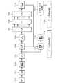
図1に、本実施の形態に係る無線通信システムを示す。図1に示すように、本無線通信システムは、第1無線通信信号106を生成して送信する第1無線通信装置たる基地局101、第1無線通信信号106の通信方式と異なる通信方式の第2無線通信信号107,108を生成して送信する第2無線通信装置たる基地局104、第1及び第2無線通信信号106,107を受信する第3無線通信装置たる移動機102、及び、その他の移動機103,105を備える。 FIG. 1 shows a radio communication system according to the present embodiment. As shown in FIG. 1, the wireless communication system generates a first
このうち、基地局104は既存の通信方式の基地局であり、例えばW−CDMA基地局である。すなわち、基地局104の送信する第2無線通信信号107,108は、W−CDMA信号である。なお、基地局104において、TDD(Time Division Duplex)が採用されているか、またはFDD(Frequency Division Duplex)が採用されているかは問わない。また、基地局104はW−CDMA基地局以外にも、例えばTD−SCDMA(Time Division Synchronous Code Division Multiple Access)基地局であってももよいし、GSM(Global System for Mobile Communications)やPDC(Personal Digital Cellular)のようなTDMA(Time Division Multiple Access)基地局であってもよい。その他にも、基地局104は、PHS(Personal Handyphone System)基地局であってもよいし、WiMAX(IEEE802.16d/e:Worldwide Interoperability for Microwave Access)基地局であってもよい。 Among these, the
一方、基地局101は、基地局104の送信する第2無線通信信号107,108とは異なる通信方式の第1無線通信信号106を生成して送信する基地局であって、例えばW−CDMAのLTE(Super3Gサービス)に対応した、OFDM基地局である。すなわち、基地局101の送信する第2無線通信信号106は、Super3Gサービスに対応したOFDM信号である。なお、基地局101は、OFDM基地局以外にも、その他のマルチキャリアを用いた通信システムの基地局であってもよい。 On the other hand, the
移動機105は、基地局104からの第2無線通信信号108を受信しているW−CDMA移動機であり、移動機102は、基地局101からの第1無線通信信号106を受信しているSuper3Gサービスに対応した移動機である。また、移動機103も、Super3Gサービスに対応した移動機である。なお、第2無線通信信号107は、基地局104からの干渉信号として移動機102に伝播している。 The
次に、移動機102が受信する第1及び第2無線通信信号106,107の周波数アロケーション例を説明する。図2は、この周波数アロケーション例を説明する図である。W−CDMA信号たる第2無線通信信号107は、例えばW−CDMA信号W1〜W3のように、5MHz分の周波数帯域を3波分有する信号である。 Next, an example of frequency allocation of the first and second wireless communication signals 106 and 107 received by the
また、OFDM信号たる第1無線通信信号106は、例えばOFDM信号O1のように、6本の直交多重化が行われた、5MHz分の周波数帯域を有する信号である。なお、図2に示されているように、第1無線通信信号106と第2無線通信信号107とは、周波数軸上にて隣接して配置されている。 Further, the first
すなわち、図2の周波数アロケーション例では、例えば2GHz帯の信号の最大周波数幅20MHz内のうち、5MHz幅のW−CDMA信号の使用帯域を4波から3波(W1〜W3)に減少させて、その減少させた帯域にSuper3Gサービスに対応したOFDM信号O1を挿入している。 That is, in the frequency allocation example of FIG. 2, for example, within the maximum frequency width 20 MHz of the signal of 2 GHz band, the use band of the W-CDMA signal of 5 MHz width is reduced from 4 waves to 3 waves (W1 to W3), An OFDM signal O1 corresponding to the Super3G service is inserted in the reduced band.
ここで、Super3Gサービスの方が従来方式のW−CDMAよりも周波数効率が良いとすると、やがてはW−CDMA信号W1〜W3の3波分(15MHz)を、2波分(10MHz)、1波分(5MHz)と段階的に減少させて、その分、OFDM信号O1を拡張することになると予想される。 Here, assuming that the frequency efficiency of the Super3G service is better than that of the conventional W-CDMA, eventually, three waves (15 MHz) of the W-CDMA signals W1 to W3 are converted into two waves (10 MHz) and one wave. It is expected that the OFDM signal O1 will be expanded by that amount in steps (5 MHz).
この場合、移動機102においては、将来的に拡張されるOFDM信号O1にも対応するために、図2中のOFDM信号O1の5MHz分以外の周波数帯域のOFDM信号をも受信可能とする必要がある。すなわち、本願では、第3無線通信装置たる移動機102に、第1無線通信信号106及び第2無線通信信号107、つまり、OFDM信号O1及びW−CDMA信号W1〜W3の合計の周波数帯域(20MHz分)の信号が通過するよう、受信した第1無線通信信号106及び第2無線通信信号107を固定の通過帯域(20MHz分)で選択的に通過させる固定バンドパスフィルタと、その固定バンドパスフィルタを通過した信号をさらに可変の通過帯域で選択的に通過させて、OFDM信号O1のみを取り出す可変バンドパスフィルタとを含ませる。 In this case, in order to cope with the OFDM signal O1 that will be expanded in the future, the
図3は、本実施の形態に係る第3無線通信装置たる移動機102のブロック図である。移動機102は、上述の固定バンドパスフィルタ701と、固定バンドパスフィルタ701からの出力信号を増幅するLNA(Low Noise Amplifier)702と、LNA702からの出力信号(無線周波数信号)をベースバンド信号にダウンコンバートし、その後、直交復調(ダイレクトコンバージョン)を行う直交復調部703とを備える。 FIG. 3 is a block diagram of
さらに、移動機102は、直交復調部703からの出力信号に対してA/D(Analog to Digital)変換を行うA/D変換器704と、A/D変換器704からの出力信号を入力とする上述の可変バンドパスフィルタ705と、可変バンドパスフィルタ705の出力信号からOFDM信号のギャップインターバル(GI)を除去するGI除去部706と、GI除去部706からの出力信号をシリアル−パラレル変換するS/P変換部707と、S/P変換部707からの出力信号に対して高速フーリエ変換を行うFFT部708と、FFT部708からの出力信号をパラレル−シリアル変換するP/S変換部709と、P/S変換部709からの出力信号に対して多値変調の復調処理を行うデータ復調部710とを備える。 Further, the
FFT部708では、高速フーリエ変換以外にも必要に応じて、既知信号系列等からの伝送路推定や位相補正を行っても良い。また、データ復調部710では、多値変調の復調処理以外にも必要に応じて、デインターリーブ、誤り訂正処理等を行っても良い。 In addition to the fast Fourier transform, the
なお、OFDM信号O1の将来の拡張性を考慮して、固定バンドパスフィルタ701では、2GHz帯の信号の最大周波数幅20MHzの信号が通過する固定の通過帯域を採用しておけばよい。固定バンドパスフィルタ701は、通過帯域以外の周波数帯の不要波を除去する機能を有する。また、可変バンドパスフィルタ705には、フィルタ係数の変更により、所望の通過帯域(図2の例ではOFDM信号O1の5MHz分)を通過させることが可能な、プログラマブルデジタルフィルタを採用すればよい。 In consideration of the future expandability of the OFDM signal O1, the fixed
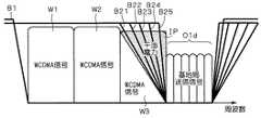
図4は、各バンドパスフィルタによるフィルタリング例を示す図である。図4に示す通り、フィルタリング特性B1は、W−CDMA信号W1〜W3の15MHz分およびOFDM信号O1の5MHz分の合計20MHz分を通過帯域としており、一方、フィルタリング特性B2は、OFDM信号O1の5MHz分のみを通過帯域としている。 FIG. 4 is a diagram illustrating an example of filtering by each bandpass filter. As shown in FIG. 4, the filtering characteristic B1 has a total of 20 MHz for 15 MHz of the W-CDMA signals W1 to W3 and 5 MHz of the OFDM signal O1, and the filtering characteristic B2 is 5 MHz of the OFDM signal O1. Only the minute is used as the passband.
さて、第1無線通信信号106には、可変バンドパスフィルタ705における可変の通過帯域を指示する制御情報が含まれている。そして、その制御情報がデータ復調部710にて復調され、データ復調部710から可変バンドパスフィルタ705へのフィードバック信号として可変バンドパスフィルタ705に与えられることにより、可変バンドパスフィルタ705は、第2無線通信信号107(図2の例ではW−CDMA信号W1〜W3の15MHz分)を除去しつつ、第1無線通信信号106(図2の例ではOFDM信号O1の5MHz分)を選択的に通過させることが可能となる。 The first
次に、可変バンドパスフィルタ705における可変の通過帯域を指示する制御情報について述べる。基地局101は、第1無線通信信号106により移動機102との間で、パケットや音声のデータをやり取りする。それに加えて、基地局101は、可変バンドパスフィルタ705における可変の通過帯域を指示する制御情報を第1無線通信信号106に含ませて、移動機102に送信する。 Next, control information for instructing a variable pass band in the variable
その送信方法としては、報知チャネルを用いた基地局エリア(セクタ構成をとっているときにはセクタ内エリア)からの報知として通知する方法か、あるいは、個別チャネル毎の制御チャネルを用いた通信として通知する方法を採用すればよい。また、複数の移動機をグループ化して1つの制御チャネルを用いて通信を行う場合も、個別チャネル毎の制御チャネルに準じた通知方法を採用すればよい。 As a transmission method, notification is made as a notification from a base station area using a broadcast channel (intra-sector area when a sector configuration is adopted), or as a communication using a control channel for each individual channel. The method should be adopted. Also, when a plurality of mobile devices are grouped and communicated using one control channel, a notification method according to the control channel for each individual channel may be employed.
個別チャネルの制御チャネルを使用する場合には、Super3Gサービスにて規定されたL1(Layer1)によるシグナリングでもよいし、Super3Gサービスにて規定されたL2(Layer2)やL3(Layer3)のメッセージとして通知しても良い。 When the control channel of the dedicated channel is used, signaling by L1 (Layer 1) defined by the Super3G service may be performed, or a L2 (Layer2) or L3 (Layer3) message defined by the Super3G service is notified. May be.
メッセージを授受する4つの例を図5〜8に示す。図5〜8は、可変バンドパスフィルタにおける通過帯域を指示する制御情報を授受する、各シーケンス例を示す図である。 Four examples of sending and receiving messages are shown in FIGS. FIGS. 5 to 8 are diagrams showing examples of sequences for transmitting / receiving control information indicating a pass band in the variable band pass filter.
図5は、基地局から移動機への報知チャネルを用いるシーケンス例である。基地局、セクタ毎に周辺の伝搬環境に合わせて最適な報知チャネルを通知する。移動機は報知チャネルの変更を認知し次第、周波数帯域を変更する。 FIG. 5 is a sequence example using a broadcast channel from a base station to a mobile device. For each base station and sector, an optimal broadcast channel is notified in accordance with the surrounding propagation environment. As soon as the mobile station recognizes the change of the broadcast channel, the mobile station changes the frequency band.
図6は、L1によるシグナリングを用いるシーケンス例である。フィルタ特性を変更する時間分、実データ送信より特定の時間分だけ先行して送信すればよい。制御情報を受信した移動機は、当該シグナリングを受信したのち特定時間後のデータから(実データ送信前に予告して送信した場合)、周波数変更を行えばよい。 FIG. 6 is a sequence example using signaling by L1. The transmission may be performed by a specific time before the actual data transmission for the time for changing the filter characteristics. The mobile device that has received the control information may change the frequency from the data after a specific time after receiving the signaling (when it is transmitted in advance before transmitting the actual data).
また、図7及び図8は例としてL3によるメッセージを用いるシーケンス例である。図7は、基地局からのL3による周波数変更要求のメッセージに対して、移動機が即時に変更を実施するとともに応答メッセージを返す例である。また、図8は、基地局からのL3による周波数変更準備要求のメッセージに対して、移動機が変更のための準備を要する旨を通知し、基地局がcommitメッセージを返答する例である。commitメッセージでは少なくとも周波数帯域を変更するタイミングが指定されており、移動機がそのタイミング以降に周波数帯域を変更可能なタイミングを指定する。指定するタイミングはシステム的に一意に決定できるタイミングで、例えば、報知チャネルの周期に合わせたタイミングとすればよい。 FIG. 7 and FIG. 8 are sequence examples using messages by L3 as an example. FIG. 7 is an example in which the mobile device immediately changes the response message and returns a response message in response to the frequency change request message by L3 from the base station. Further, FIG. 8 is an example in which the mobile station notifies that a preparation for change is required in response to a frequency change preparation request message by L3 from the base station, and the base station returns a commit message. In the commit message, at least the timing for changing the frequency band is specified, and the mobile station specifies the timing at which the frequency band can be changed after that timing. The designated timing is a timing that can be uniquely determined systematically, for example, a timing that matches the period of the broadcast channel.
一般に、データフレームは0.5ms〜40ms程度に無線伝送用に区切られるが、報知情報はデータサイズが大きく、長時間に渡ってTDM(Time Division Multiplex)伝送、あるいは、FDM(Frequency Division Multiplex)伝送、あるいは、CDM(Code Division Multiple)伝送、がなされている。あるいは、報知チャネルとは別に、十分長時間のシステムクロックを定義し、そのタイミングで定義してもよい。 In general, a data frame is divided into about 0.5 ms to 40 ms for wireless transmission, but broadcast information has a large data size, and TDM (Time Division Multiplex) transmission or FDM (Frequency Division Multiplex) transmission over a long period of time. Alternatively, CDM (Code Division Multiple) transmission is performed. Alternatively, apart from the broadcast channel, a sufficiently long system clock may be defined and defined at that timing.
報知チャネルを使用するときには、シンプルな制御でエリア内の基地局に対して制御が可能となり、また、個別チャネルを使用するときには、ダイナミックに使用する周波数を切り替えることが可能となり、周波数利用効率が向上する。そして、commitメッセージを使用すると、ダイナミックに周波数を切替ながらも、切替タイミングを送信側と受信側で正確に合わせることができるので効率の良い変更ができる。 When using the broadcast channel, it is possible to control the base stations in the area with simple control, and when using an individual channel, it is possible to dynamically switch the frequency to be used, improving frequency utilization efficiency. To do. If the commit message is used, the switching timing can be accurately matched between the transmission side and the reception side while the frequency is dynamically switched, so that an efficient change can be made.
なお、上記においては、可変バンドパスフィルタ705の配置例として、直交復調部7によるベースバンド信号変換の後段を採用したが、それ以外にも例えば、無線周波数信号をIF(Intermidiate Frequency)に変換する機能を設けて、その後段に可変バンドパスフィルタ705を配置し、IF信号に対して可変バンドパスフィルタ705を通過させても良い。 In the above, as the arrangement example of the
また、上記においては、可変バンドパスフィルタ705の構成例として、デジタルフィルタを示したが、デジタルフィルタではなくプログラマブルなアナログフィルタを使用してもよい。また、可変バンドパスフィルタ705の構成として、複数のフィルタ特性を有するフィルタを並列配置して切替えて使用する方法でもよいし、これらの方法とシンセサイザによる中央周波数の切り替えを組み合わせる方法でもよい。 In the above description, a digital filter is shown as an example of the configuration of the
なお、可変バンドパスフィルタ705に関し、キャリア間が直交するOFDM等のマルチキャリア通信方式では、マルチキャリア内の一部を使う場合でも、それに合わせて飛び飛びの周波数領域を通過させるようなフィルタにする必要はない。 Regarding the
本実施の形態に係る無線通信システムおよび無線通信装置によれば、第1無線通信信号106には、可変バンドパスフィルタ705における可変の通過帯域を指示する制御情報が含まれ、制御情報が可変バンドパスフィルタ705に与えられることにより、可変バンドパスフィルタ705は、第2無線通信信号107を除去しつつ、第1無線通信信号106を選択的に通過させることが可能である。よって、同一周波数帯域内に、異なる通信方式の複数の送信信号が存在する場合に、互いに干渉なく各送信信号による通信を行うことが可能な無線通信システムおよび無線通信装置が実現できる。そして、可変バンドパスフィルタ705が可変の通過帯域となっていることから、第1無線通信信号106の将来的な周波数拡張にも対応することができる。 According to the radio communication system and radio communication apparatus according to the present embodiment, first
また、上記構成を採ることにより、W−CDMA信号及びOFDM信号が周辺電波環境の都合により、いわゆるキャリアラスタが行われて周波数オフセットが生じた場合であっても、フィルタ係数を変更することで周波数効率を最大にすることができる。ここで、キャリアラスタとは、基地局101および基地局104によって、第1無線通信信号106および第2無線通信信号107の、周波数軸上における配置が移動させられることを指す。 Further, by adopting the above configuration, even when the W-CDMA signal and the OFDM signal have a frequency offset due to the so-called carrier raster due to the circumstances of the surrounding radio wave environment, the frequency can be changed by changing the filter coefficient. Efficiency can be maximized. Here, the carrier raster means that the
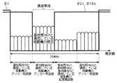
図9はキャリアラスタが行われる場合の第1及び第2無線通信信号106,107の周波数アロケーション例を示す図である。この図9では例として、キャリアラスタL1によって、OFDM信号O1が、そのサブキャリア1つ分O1aが減少したOFDM信号O1bとなっている。 FIG. 9 is a diagram showing an example of frequency allocation of the first and second wireless communication signals 106 and 107 when carrier raster is performed. In FIG. 9, as an example, the OFDM signal O1 is reduced to the OFDM signal O1b by one subcarrier O1a by the carrier raster L1.
このときに、OFDM信号O1の帯域幅5MHzよりも、サブキャリア1つ分PO1aだけ狭い帯域を通過帯域とするよう、基地局101からの制御情報を更新することで、可変バンドパスフィルタ705における通過帯域を変更することができ、隣接するW−CDMA信号W3からの干渉波が最小に抑えられる。 At this time, the control information from the
すなわち、本実施の形態に係る無線通信システムによれば、第1無線通信信号106および第2無線通信信号107の、周波数軸上における配置が移動させられた場合において、可変バンドパスフィルタ705が、第2無線通信信号107を除去しつつ、第1無線通信信号106を選択的に通過させることが可能となるよう、制御情報が更新される。よって、いわゆるキャリアラスタが行われた場合にも、互いに干渉なく各送信信号による通信を行うことができる。 That is, according to the radio communication system according to the present embodiment, when the arrangement of the first
なお、上記においては移動機102における周波数帯域制御の説明をしたが、上記の内容は移動機102と基地局101とを入れ替えても成立する。上記においては、基地局101を、第1無線通信信号106を生成して送信する第1無線通信装置と考え、移動機102を、第1及び第2無線通信信号106,107を受信する第3無線通信装置と考えることを前提としていた。 In the above description, the frequency band control in the
しかし、移動機102にも無線通信信号を生成して送信する機能(図示せず)はあり、また、基地局101にも移動機102からの無線通信信号および第2無線通信装置たる基地局104からの第2無線通信信号107を受信する機能がある。すなわち、基地局101内には、受信ブロック101aが存在し、受信ブロック101aは、図3に示した移動機のブロック図と同様の構成を有する。 However, the
すなわち、移動機102を、第1無線通信信号106を生成して送信する第1無線通信装置と考え、基地局101を、第1及び第2無線通信信号106,107を受信する第3無線通信装置と考えることもできる。 That is, the
なお、基地局101,104がそれらを統合する基地局上位装置を有する場合や、あるいは、基地局101,104間において無線リソースの管理が連携できていないシステムであっても、本発明を適用することができる。 Note that the present invention is applied even when the
(実施の形態2)
本実施の形態は、実施の形態1に係る無線通信システム及び無線通信装置の変形例であって、第3無線通信装置たる移動機102に、更なる可変バンドパスフィルタと、その通過信号の電力を測定する電力測定部と、測定結果を送信する送信処理部とを設け、基地局101が測定結果を受けて、第1無線通信信号106の信号特性を変更する、および/または、可変バンドパスフィルタ705における濾波特性を変更する情報を制御情報に含めるようにしたものである。(Embodiment 2)
The present embodiment is a modification of the wireless communication system and the wireless communication apparatus according to Embodiment 1, in which a
本実施の形態に係る無線通信システムの構成は、図1と同様であるので、説明を省略する。ただし、第1及び第2無線通信信号106,107を受信する第3無線通信装置たる移動機102の構成は、図3とは異なっている。 The configuration of the radio communication system according to the present embodiment is the same as that in FIG. However, the configuration of the
図10に、本実施の形態に係る無線通信装置たる移動機102のブロック図を示す。この移動機102は、図3に示したのと同様の機能及び接続構成の、固定バンドパスフィルタ701、LNA702、直交復調部703、A/D変換器704、可変バンドパスフィルタ705、GI除去部706、S/P変換部707、FFT部708、P/S変換部709及びデータ復調部710を備える。 FIG. 10 shows a block diagram of
これらに加えて移動機102は更に、A/D変換器704からの出力信号を入力とする第2の可変バンドパスフィルタ711と、可変バンドパスフィルタ711を通過した信号の電力を測定する電力測定部712と、電力測定部712における測定結果をシグナリングに適した形式に整形するシグナリング生成部713と、シグナリング生成部713の出力信号に対して、多値変調およびSC(Single Carrier)−FDMA等の所要の変調処理を施すデータ変調処理部715と、データ変調処理部715の出力信号をアナログ化し、アップコンバージョン及び電力増幅等も行って、第1無線通信装置たる基地局101に送信するデータ送信処理部714とを備える。 In addition to these, the
本実施の形態においては、第1無線通信信号106に、可変バンドパスフィルタ711における可変の通過帯域を指示する制御情報も含ませる。そして、その制御情報がデータ復調部710にて復調され、データ復調部710から可変バンドパスフィルタ711へのフィードバック信号として可変バンドパスフィルタ711に与えられることにより、可変バンドパスフィルタ711は、第1無線通信信号106(図2の例ではOFDM信号O1の5MHz分)を除去しつつ、第2無線通信信号107の少なくとも一部(図2の例では例えばOFDM信号O1に隣接するW−CDMA信号W3の一部)を選択的に通過させることが可能となる。 In the present embodiment, the first
こうして、可変バンドパスフィルタ711にて濾波された信号は、移動機102の処理すべきOFDM信号O1に隣接するW−CDMA信号W3の受信電力を電力測定部712にて測定するのに使用する。受信電力の測定結果は、データ送信処理部714により、基地局101に送信される。そして、基地局101は、その測定結果を受け、第2無線通信信号107の送信電力の値に応じて、第1無線通信信号106の信号特性を変更する、または、可変バンドパスフィルタ705における濾波特性を変更する情報を制御情報に含めて送信する、または、その両者を行うのである。 Thus, the signal filtered by the
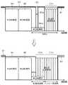
次に、図11及び図12を用いて、より詳細な動作の説明を行う。図11は、第1無線通信信号106の周波数軸上における配置を第2無線通信信号107の領域にまで拡大することにより、第1無線通信信号106の信号特性を変更する例を示す図である。また、図12は、図11における変更前後の第1及び第2無線通信信号106,107の時間アロケーション例を示す図である。 Next, a more detailed operation will be described with reference to FIGS. FIG. 11 is a diagram illustrating an example in which the signal characteristic of the first
なお、図11においては、W−CDMA信号W3の信号強度が低い場合を示しており、その符号をW3aと表示している。また、OFDM信号O1の符号表記については、後述するアンカー周波数O1dと拡張周波数O1eとに改めている。 Note that FIG. 11 shows a case where the signal strength of the W-CDMA signal W3 is low, and the code thereof is denoted as W3a. Further, the code notation of the OFDM signal O1 is changed to an anchor frequency O1d and an extension frequency O1e described later.
図11においては、固定バンドパスフィルタ701のフィルタリング特性B1は、実施の形態1の場合と同様、W−CDMA信号W1〜W3の15MHz分およびOFDM信号O1の5MHz分の合計20MHz分を通過帯域としている。また、図11の上部に示した濾波特性変更前の状態では、可変バンドパスフィルタ705のフィルタリング特性B2も、実施の形態1の場合と同様、OFDM信号O1の5MHz分のみを通過帯域としている。 In FIG. 11, the filtering characteristic B1 of the fixed
可変バンドパスフィルタ711のフィルタリング特性B3においては、例としてOFDM信号O1に隣接するW−CDMA信号W3aの一部が、可変の通過帯域B3aとされる。そして、可変バンドパスフィルタ711を通過した信号の電力が電力測定部712により測定され、測定された電力値は、シグナリング生成部713にて充分に精度が取れるまで平均化される。その後、受信電力の測定結果の情報は、データ変調処理部715およびデータ送信処理部714を経由して、基地局101に送信される。なお、測定結果の情報は、基地局101を介して基地局101の上位装置に送信されてもよい。 In the filtering characteristic B3 of the
基地局101は、測定結果の情報を受けて、モニタしている可変バンドパスフィルタ711の通過信号の電力の値、すなわちW−CDMA信号W3の電力値が、ある閾値よりも小さくなったときに、使用する第1無線通信信号106の信号特性を変更するシグナリングを移動機102へと送信した後、データの送信を開始する。より具体的には、基地局101は、図11の下部に示すように、第1無線通信信号106の周波数軸上における配置を第2無線通信信号107の領域にまで拡大することにより、第1無線通信信号106の信号特性を変更し、また、可変バンドパスフィルタ705が、そのフィルタリング特性B2を変更して、第2無線通信信号107を除去しつつ、拡大後の第1無線通信信号106を選択的に通過させることが可能となるよう、制御情報を更新する。 When the
図12の、変更前後の第1及び第2無線通信信号106,107の時間アロケーション例に示すとおり、OFDM信号O1は、基地局101による第1無線通信信号106の周波数配置拡大後は、アンカー周波数O1dに加えて拡張周波数O1eにも信号を有するようになる。なお、本願では、拡大前の第1無線通信信号106の周波数軸上における配置をアンカー周波数領域と定義し、拡大後の第1無線通信信号106のうち増大分の、周波数軸上における配置を拡張周波数領域と定義する。 As shown in the time allocation example of the first and second radio communication signals 106 and 107 before and after the change in FIG. 12, the OFDM signal O1 is an anchor frequency after the frequency arrangement of the first
本実施の形態に係る無線通信システム及び無線通信装置によれば、電力測定部712が可変バンドパスフィルタ711を通過した信号の電力を測定し、その電力測定部712における測定結果を第1無線通信装置たる基地局101が受け、第2無線通信信号107の送信電力の値に応じて、第1無線通信信号106の信号特性を変更する。よって、周波数軸上にて第1無線通信信号106に隣接して配置された、第2無線通信信号107の送信電力の状況に応じて、第1無線通信信号106の信号を増強することができる。 According to the radio communication system and radio communication apparatus according to the present embodiment,
そして、第1無線通信装置たる基地局101が、第1無線通信信号106の周波数軸上における配置を第2無線通信信号107の領域にまで拡大することにより、第1無線通信信号106の信号特性を変更する。よって、第2無線通信信号107の送信電力の状況に応じて、第1無線通信信号106の周波数帯域を拡張することができ、第1無線通信信号106の高速通信を図ることができる。 Then, the
なお、第1無線通信信号106の信号特性の変更は、図11及び12に示したような第1無線通信信号106の周波数配置の拡大だけに限られず、例えば第1無線通信信号106の、周波数軸上における少なくとも一部の送信信号強度を増強することにより行なってもよい。 Note that the change in the signal characteristics of the first
すなわち、例えば基地局101は、モニタしている可変バンドパスフィルタ711の通過信号の電力の値、すなわちW−CDMA信号W3の電力値の信号強度の分だけ、第1無線通信信号106の信号強度を増大させてもよい。例えばW−CDMA信号W3の平均信号強度が3dBであれば、第1無線通信信号106の信号強度を3dB増加させる、などすればよい。 That is, for example, the
このように、第1無線通信装置たる基地局101が、第1無線通信信号106の、周波数軸上における少なくとも一部の送信信号強度を増強することにより、第1無線通信信号106の信号特性を変更すれば、第2無線通信信号107の送信電力の状況に応じて、第1無線通信信号106を増強することができ、第1無線通信信号106の確実な通信を図ることができる。 As described above, the
なお、第1無線通信信号106の周波数配置の拡大と第1無線通信信号106の送信信号強度の増強とを同時に行う場合には、基地局101が送信電力を増大させるのは、干渉波たるW−CDMA信号W3が存在する周波数帯部分のみとすればよい。こうすれば、最も周波数使用効率が高くなる。 When the frequency arrangement of the first
一方、移動機102の受信周波数帯において一律に、基地局101は第1無線通信信号106を増強してもよい。移動機102は、基地局101からの送信電力増加のシグナリングにより得られた第1無線通信信号106の増大分の情報を、共通チャネルおよびコンテンションチャネルの送信電力値や、個別チャネル(共有チャネル含む)送信開始時の初期送信電力値や、通信中の個別チャネル(共有チャネル含む)の送信電力値の、オフセットとして使用すればよい。 On the other hand, the
また、電力測定部712における測定結果を基地局101が受けた場合に、第1無線通信信号106の信号特性を変更するのではなく、第2無線通信信号107の送信電力の値に応じて、可変バンドパスフィルタ705における濾波特性を変更する情報を制御情報に含めるようにしてもよい。すなわち、可変バンドパスフィルタ705における消費電力は、濾波特性を急峻にするほど大きいことを考慮し、可変バンドパスフィルタ705における濾波特性を段階分けしておいてもよい。 Further, when the
多くのユーザと大容量の通信を行うようなトラフィックが高い状態では、可変バンドパスフィルタ705における消費電力の増大があるとしても、多ユーザの峻別が可能なよう、急峻な濾波特性が求められる。一方、トラフィックが低い状態では隣接W−CDMAが使われていてもフィルタスルーにし移動機の消費電力を優先する運用を行う。 In a state where the traffic for carrying out large-capacity communication with many users is high, even if there is an increase in power consumption in the
図13は、可変バンドパスフィルタ705における可変の濾波特性を示す図である。図13に示すように、現実の濾波特性はなだらかな特性となっており、隣接チャネルたる第2無線通信信号107の干渉波IPを完全には0とすることができず、干渉波が漏れて入ってくる。 FIG. 13 is a diagram illustrating variable filtering characteristics in the
そこで、可変バンドパスフィルタ705における濾波特性を、特性B21〜B25にまで変化可能としておく。そして、基地局101は、電力測定部712における測定結果に基づいて、第2無線通信信号107の送信電力が比較的高い場合には、可変バンドパスフィルタ705における濾波特性が急峻となるよう濾波特性を変更する情報を制御情報に含め、第2無線通信信号107の送信電力が比較的低い場合には、可変バンドパスフィルタ705における濾波特性がなだらかとなるよう濾波特性を変更する情報を制御情報に含める。可変バンドパスフィルタ705は、この制御情報に基づいて、濾波特性を特性B21〜B25のうち適したものに変更する。 Therefore, the filtering characteristics in the
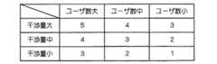
図14は、使用ユーザ数と干渉量に対する濾波特性の数値例を示す図である。図14では、例えば濾波特性の数値1を5dBの急峻特性(隣接5MHzあたりの平均減衰量を言う)とし、数値2を10dBの、数値3を20dBの、数値4を30dBの、数値5を40dBの、各急峻特性としている。そして、数値1の場合が図13における特性B21に該当し、同様に数値2の場合が特性B22に、数値3の場合が特性B23に、数値4の場合が特性B24に、数値5の場合が特性B25に、それぞれ該当する。 FIG. 14 is a diagram illustrating a numerical example of the filtering characteristics with respect to the number of users and the amount of interference. In FIG. 14, for example, the filtering characteristic value 1 is a steep characteristic of 5 dB (referring to the average attenuation per adjacent 5 MHz), the
このように、本実施の形態では、電力測定部712が可変バンドパスフィルタ711を通過した信号の電力を測定し、その電力測定部712における測定結果を第1無線通信装置たる基地局101が受け、第2無線通信信号107の送信電力の値に応じて、可変バンドパスフィルタ705における濾波特性を変更する情報を制御情報に含めてもよい。これにより、周波数軸上にて第1無線通信信号106に隣接して配置された、第2無線通信信号107の送信電力の状況に応じて、可変バンドパスフィルタ705における濾波特性を急峻にしたりすることができる。 As described above, in the present embodiment, the
そして、第1無線通信装置たる基地局101は、第2無線通信信号107の送信電力が比較的高い場合には、可変バンドパスフィルタ705における濾波特性が急峻となるよう濾波特性を変更する情報を制御情報に含め、第2無線通信信号107の送信電力が比較的低い場合には、可変バンドパスフィルタ705における濾波特性がなだらかとなるよう濾波特性を変更する情報を制御情報に含める。一般に、可変バンドパスフィルタ705において濾波特性が急峻であれば、信号の峻別をより正確に行えるものの、可変バンドパスフィルタ705での消費電力が増大してしまう。よって、第2無線通信信号107の送信電力の状況に応じて、第2無線通信信号107の送信電力が比較的高い場合には、消費電力を犠牲にして可変バンドパスフィルタ705における濾波特性を高めることができ、一方、第2無線通信信号107の送信電力が比較的低い場合には、濾波特性をなだらかにして、可変バンドパスフィルタ705における消費電力を削減することができる。 Then, when the transmission power of the second
なお、可変バンドパスフィルタ705における濾波特性の変更と、第1無線通信信号106の、周波数軸上における少なくとも一部の送信信号増強、あるいは、第1無線通信信号106の周波数配置の拡大による、第1無線通信信号106の信号特性の変更とを同時に行っても良い。 It is to be noted that the change in the filtering characteristics in the
(実施の形態3)
本実施の形態は、実施の形態2に係る無線通信システム及び無線通信装置の変形例であって、アンカー周波数領域内に、パイロットチャネルに関する信号、ページングチャネルに関する信号、及び、報知チャネルに関する信号のうち少なくとも一つを配置したものである。(Embodiment 3)
The present embodiment is a modification of the radio communication system and radio communication apparatus according to the second embodiment, and among the signals related to the pilot channel, the paging channel, and the broadcast channel in the anchor frequency region At least one is arranged.
本実施の形態に係る無線通信システムの構成も、図1と同様であるので、説明を省略する。また、移動機102の構成も、図10と同様であるので、説明を省略する。 The configuration of the radio communication system according to the present embodiment is also the same as that in FIG. Also, the configuration of the
次に、図15及び図16を用いて、本実施の形態に係る無線通信システムの動作の説明を行う。図15は、第1無線通信信号106の周波数軸上における配置を第2無線通信信号107の領域にまで拡大することにより、第1無線通信信号106の信号特性を変更する例を示す図である。また、図16は、図15における変更前後の第1及び第2無線通信信号106,107の時間アロケーション例を示す図である。 Next, the operation of the radio communication system according to the present embodiment will be described with reference to FIGS. 15 and 16. FIG. 15 is a diagram illustrating an example in which the signal characteristic of the first
なお、図15及び図16においては、20MHzの最大周波数幅内に、5MHz幅のW−CDMA信号がW2,W3aの2波分存在し、キャリアラスタL1により、W−CDMA信号W2,W3aの配置が周波数軸上において移動させられている。また、残りの周波数帯にはOFDM信号が存在する。OFDM信号には、アンカー周波数O1dに加えて拡張周波数O1eが含まれる。 In FIGS. 15 and 16, there are two W-CDMA signals of W2 and W3a within the maximum frequency width of 20 MHz, and the arrangement of the W-CDMA signals W2 and W3a by the carrier raster L1. Is moved on the frequency axis. In addition, OFDM signals exist in the remaining frequency bands. The OFDM signal includes an extension frequency O1e in addition to the anchor frequency O1d.
図16の、変更前後の第1及び第2無線通信信号106,107の時間アロケーション例に示すとおり、OFDM信号は、実施の形態2の場合と同様、基地局101による第1無線通信信号106の周波数配置拡大後は、アンカー周波数O1dに加えて拡張周波数O1eにも信号を有するようになる。 As shown in the time allocation example of the first and second radio communication signals 106 and 107 before and after the change in FIG. 16, the OFDM signal is the same as that of the second embodiment in that the first
アンカー周波数領域としては、周波数帯の大きさを変更する頻度が低い周波数領域、あるいは、他の通信方式の通信システムと周波数的な重なりがない周波数領域、あるいは、信号が直交しない同一の通信方式の通信システムとの周波数的な重なりがない周波数領域(少なくともアンカー周波数同士の重なりがない領域)、あるいは、基地局の立地条件として通信に影響のない程度に干渉レベルが低い周波数領域、などを採用することができる。 The anchor frequency region is a frequency region where the frequency band size is not changed frequently, a frequency region where there is no frequency overlap with a communication system of another communication method, or the same communication method where signals are not orthogonal. Adopt a frequency region where there is no frequency overlap with the communication system (at least a region where there is no overlap between anchor frequencies) or a frequency region where the interference level is low enough not to affect communication as a location condition of the base station. be able to.
また、拡張周波数領域としては、周波数帯の大きさを変更する頻度が高い周波数領域、あるいは、他の通信方式の通信システムと周波数的な重なりがある周波数領域、あるいは、信号が直交しない同一の通信方式の通信システムとの周波数的な重なりがある周波数領域(少なくとも他の通信システムのアンカー周波数領域と重なりがある領域)、あるいは、基地局の立地条件としてトラフィック量が多い時は通信に影響が出る程度の干渉レベルとなる周波数領域、などを採用すればよい。 The extended frequency range includes a frequency range where the frequency band is frequently changed, a frequency range where there is a frequency overlap with a communication system of another communication system, or the same communication where signals are not orthogonal. Communication is affected when there is a large amount of traffic in the frequency range where there is a frequency overlap with the communication system of the system (at least the region where there is an overlap with the anchor frequency region of other communication systems) or the location conditions of the base station What is necessary is just to employ | adopt the frequency area | region etc. which become a moderate interference level.
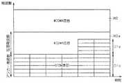
第1無線通信信号106には、パイロットチャネルに関する信号、ページングチャネルに関する信号、及び、報知チャネルに関する信号のうち少なくとも一つが含まれる。そして、本実施の形態においては、図16に示すように、アンカー周波数領域内に、共通パイロットチャネル信号PL1や、報知チャネル信号RP1、ページングチャネル信号PG1などの共通チャネル信号が配置されている。 The first
データの送受信をしないで、無線接続用の制御チャネルの信号処理を行っている際には、例えば可変バンドパスフィルタ705を、アンカー周波数O1dの領域の信号のみ通過するように設定する。アンカー周波数領域の幅は、他の通信システムとの干渉を回避できる最大周波数帯域幅に設定すればよい。 When signal processing of the control channel for wireless connection is performed without transmitting / receiving data, for example, the variable
図16のように、W−CDMA信号W2,W3aにキャリアラスタL1を行う場合であっても、本発明のアンカー周波数O1dは、環境に応じて柔軟に設置することができ、アンカー周波数幅を、例えば20MHz−5MHz−5MHz−キャリアラスタ分=8MHzと設定すればよい。 As shown in FIG. 16, even when the carrier raster L1 is applied to the W-CDMA signals W2 and W3a, the anchor frequency O1d according to the present invention can be flexibly installed according to the environment. For example, 20 MHz-5 MHz-5 MHz-carrier raster = 8 MHz may be set.
本実施の形態では、アンカー周波数O1dの領域内に、パイロットチャネルに関する信号PL1、ページングチャネルに関する信号PG1、及び、報知チャネルに関する信号RP1が配置される。よって、重要な、パイロットチャネルに関する信号、ページングチャネルに関する信号、及び、報知チャネルに関する信号は、第2無線通信信号107と第1無線通信信号106とが干渉する恐れのある拡張周波数O1eの領域には配置されず、干渉による誤動作の可能性が少ない無線通信システムが実現できる。 In the present embodiment, a signal PL1 related to the pilot channel, a signal PG1 related to the paging channel, and a signal RP1 related to the broadcast channel are arranged in the region of the anchor frequency O1d. Therefore, the important signal related to the pilot channel, the signal related to the paging channel, and the signal related to the broadcast channel are in the region of the extended frequency O1e where the second
アンカー周波数O1dでは他の通信システムとの干渉がないので、パイロットチャネルに関する信号や、ページングチャネルに関する信号、及び、報知チャネルに関する信号を、アンカー周波数O1dの範囲内にて分散配置すると、周波数選択性のフェージングに強くなる。図16には、その例として報知チャネルRP1を分散配置した場合を示している。 Since there is no interference with other communication systems at the anchor frequency O1d, if the signal related to the pilot channel, the signal related to the paging channel, and the signal related to the broadcast channel are distributed within the range of the anchor frequency O1d, the frequency selectivity is improved. Strong against fading. FIG. 16 shows the case where the broadcast channel RP1 is distributed as an example.
また、第1無線通信信号106の周波数軸上における配置を第2無線通信信号107の領域にまで拡大するに際して、基地局101が、第1無線通信信号106の周波数軸上における配置の拡大に関する情報を、アンカー周波数領域からの相対的な増減量として、可変バンドパスフィルタ705における可変の通過帯域を指示する制御情報に含めておけばよい。 Further, when the arrangement of the first
具体的には拡張周波数O1eの領域をアンカー周波数O1dからの相対周波数指定とし、例えば+5MHzと指示すると、拡張周波数O1eはアンカー周波数O1dから周波数の高い方に5MHz幅となり、一方、−2MHzと指示すれば、拡張周波数O1eはアンカー周波数から周波数の低い方に2MHz幅となるようにすればよい。そして、可変バンドパスフィルタ705は、制御情報に基づいて、拡大後の第1無線通信信号106を選択的に通過させる。 Specifically, if the region of the extension frequency O1e is designated as a relative frequency from the anchor frequency O1d, for example, +5 MHz is specified, the extension frequency O1e is 5 MHz wide from the anchor frequency O1d to the higher frequency, while being indicated as -2 MHz. For example, the extension frequency O1e may be 2 MHz wide from the anchor frequency to the lower frequency side. Then, the
このようにすれば、拡大後の制御情報として、基地局101がアンカー周波数領域からの相対的な増減量のみを送信するだけでよいので、送信すべき制御情報の情報量が少なくなり、情報通信の効率化が図れる。すなわち、周波数変更に伴うシグナリング量が低減し、特に変更を高頻度に行う場合には、シグナリング量の低減により周波数利用効率が向上する。 In this way, as the control information after expansion, the
また、上記のようなアンカー周波数O1dからの相対周波数指定ではなく、基地局101が、第1無線通信信号106の周波数軸上における配置の拡大に関する情報を、拡張周波数領域の最大値からの減少量として、可変バンドパスフィルタ705における可変の通過帯域を指示する制御情報に含めるようにしてもよい。 Further, instead of specifying the relative frequency from the anchor frequency O1d as described above, the
具体的には、アンカー周波数O1dも拡張周波数O1eも、各領域の最大値が予め割り当てられた周波数番号の情報で指定するが、基地局101より拡張周波数O1eの領域をその最大値から“−375kHz”と指示されれば、拡張周波数O1eを−375kHz分だけその最大値より狭くすればよい。そして、可変バンドパスフィルタ705は、制御情報に基づいて、拡大後の第1無線通信信号106を選択的に通過させる。 Specifically, both the anchor frequency O1d and the extension frequency O1e are designated by the information of the frequency number in which the maximum value of each region is assigned in advance, but the
このようにすれば、拡大後の制御情報として、基地局101が拡張周波数領域の最大値からの減少量のみを送信するだけでよいので、送信すべき制御情報の情報量が少なくなり、情報通信の効率化が図れる。 In this way, as the control information after expansion, the
なお、他の通信方式の信号(例えば図15におけるW−CDMA信号W3a)が急激に変化して送信電力が増大する場合に備え、当該他の通信方式の信号の信号強度をモニタするために、図11の上部に示すように、移動機102の固定バンドパスフィルタ701の通過帯域内でもっとも他の通信方式の信号に近いところをある程度(例えば、モニタできる最小単位(たとえば375kHz))空けておく。これにより、移動機102と基地局101でタイミングを合わせた無送受信区間を設けるような複雑な処理が不要となる。 In addition, in order to monitor the signal strength of a signal of another communication method in preparation for a case where a signal of another communication method (for example, the W-CDMA signal W3a in FIG. 15) suddenly changes and transmission power increases, As shown in the upper part of FIG. 11, a portion (for example, the minimum unit that can be monitored (for example, 375 kHz)) that is closest to the signal of the other communication method within the pass band of the fixed
(変形例)
上述の実施の形態1〜3においては、第1無線通信信号(W−CDMA信号)を生成して送信する第1無線通信装置(基地局101)と、第1無線通信信号の通信方式と異なる通信方式の第2無線通信信号(OFDM信号)を生成して送信する第2無線通信装置(基地局104)と、第1及び第2無線通信信号を受信する第3無線通信装置(移動機102)とを備えた無線通信システムを例に採り、説明を行ったが、本願発明は、異なる通信方式の第1及び第2無線通信信号に限られるものではない。すなわち、第1及び第2無線通信信号が同じ通信方式であっても、本願の適用は可能である。(Modification)
In the above first to third embodiments, the first wireless communication device (base station 101) that generates and transmits the first wireless communication signal (W-CDMA signal) is different from the communication method of the first wireless communication signal. A second wireless communication device (base station 104) that generates and transmits a second wireless communication signal (OFDM signal) of a communication method, and a third wireless communication device (mobile device 102) that receives the first and second wireless communication signals. However, the present invention is not limited to the first and second wireless communication signals of different communication schemes. That is, even if the first and second wireless communication signals are the same communication method, the application of the present application is possible.
同一通信方式の第1及び第2無線通信信号を送信する無線通信システムにおける干渉を回避するために本発明を適用した例について、図17及び図18を用いて説明する。なお、図17は本変形例に係る無線通信システムを示す図であり、図18は、本変形例における第1及び第2無線通信信号の周波数アロケーション例を示す図である。 An example in which the present invention is applied to avoid interference in a wireless communication system that transmits first and second wireless communication signals of the same communication method will be described with reference to FIGS. 17 and 18. FIG. 17 is a diagram showing a radio communication system according to this modification, and FIG. 18 is a diagram showing an example of frequency allocation of the first and second radio communication signals in this modification.
図17に示すように、基地局1601と基地局1604とは、同一の通信方式(例えばOFDM)の基地局であり、別なクロック源で変調処理を行っているため、それらの送信する第1及び第2無線通信信号1606,1607が同期してはいない。例えば、小型の廉価な基地局であるために、基地局1604のサービスエリア1610は狭く、最大周波数幅20MHz(例)全部をサポートしてはいない。なお、移動機1605は基地局1604と通信している移動機である。 As shown in FIG. 17, the
また、基地局1601は大型の基地局である。そのため、基地局1601は、最大周波数幅20MHzの全部をサポートできており、そのサービスエリア1609は基地局1604のサービスエリア1610と重なりがある。移動機1602と1603は、基地局1601と通信している移動機である。信号1606は基地局1601と移動機1602とが通信している信号を表している。信号1607は基地局1604の信号が干渉として移動機1602に伝播している様子を示している。 The
なお、基地局1601内には、受信ブロック1601aが存在し、受信ブロック1601aは、図3または図10に示した移動機のブロック図と同様の構成を有する。 Note that a
上記のような無線通信システムの構成となっているため、基地局1601は、第1無線通信信号1606の生成にあたり、図18に示すように、小型基地局1604がサポートしていない周波数帯O1fをアンカー周波数とし、それ以外の個所O1iを拡張周波数とするようにシグナリングを行う。これにより、重なりがある同一通信方式の信号間においても、通信量が少ないときにはアンカー周波数O1fのみを使用して干渉波を除去したり、同一通信方式の基地局1604のトラフィックが少ないときには、拡張周波数O1iを広く使用して高速通信を実現したりすることができる。また、大切なチャネルの信号をアンカー周波数O1fに配置することにより、干渉から回避することが可能になり、良質な通信を確保することができる。 Since the configuration of the wireless communication system is as described above, the
また、図19は他の変形例に係る無線通信システムを示す図であり、図20は、当該他の変形例における下り周波数アロケーションを示す図、図21は、当該他の変形例における上り周波数アロケーションを示す図である。 FIG. 19 is a diagram illustrating a radio communication system according to another modification, FIG. 20 is a diagram illustrating downlink frequency allocation in the other modification, and FIG. 21 is an uplink frequency allocation in the other modification. FIG.
図19における基地局1801と1804と1811とは、直交しない3つのOFDM基地局である。なお、基地局1801内には、受信ブロック1801aが存在し、受信ブロック1801aは、図10に示した移動機のブロック図と同様の構成を有する。 The
各基地局1801、1804及び1811は、それぞれ信号が直交しない同一の通信方式を有している。また、例えば基地局1804は基地局1801の不感地を補うための小型基地局である。また、例えば基地局1811は基地局1801とは十分離れた位置にある隣接基地局である。 Each
図20に示すように、下り(基地局→移動機)信号について、基地局1801では、干渉レベルが低い周波数帯である真中の10MHzをアンカー周波数にし、その両隣を拡張周波数にしている。基地局1804では、干渉レベルが低い周波数帯である周波数が高い方の5MHzをアンカー周波数とし、それ以外の15MHzを拡張周波数としている。基地局1811では、干渉レベルが低い周波数帯である周波数が低い方の5MHzをアンカー周波数とし、それ以外の15MHzを拡張周波数としている。これにより、下りの報知情報等の共通チャネルがぶつかることなく、3つの基地局で周波数を分け合うとともに、それぞれの基地局でトラフィックが低いときには、残りの基地局で使用することができ、周波数を有効利用した高速データ通信が可能になる。 As shown in FIG. 20, for the downlink (base station → mobile station) signal, the
また、図21には図20の下り信号を送信している基地局と通信している移動機の上り信号を図示している。基地局1801と通信している移動機はアンカー周波数を図示した5MHz幅としており、上りとは異なる周波数帯としている。また、基地局1801と通信している移動機のアンカー周波数を、下りとは重なりがない周波数としてもよい。基地局1811と通信している移動機は、アンカー周波数を最も低い周波数の5MHzとしているが、拡張周波数はアンカー周波数と離れた個所にしている。 FIG. 21 illustrates an uplink signal of a mobile device communicating with a base station that transmits the downlink signal of FIG. The mobile station communicating with the
基地局1801の受信ブロック1801aにおいても、図10に示した電力測定部712を設け、上り干渉電力をモニタし、ある閾値より小さくなったとき、基地局1801が自らのフィルタを不要波を除去できるフィルタ特性に変更するよう可変バンドパスフィルタ705の設定を変更した後、移動機にデータの送信許可を送信するようにすればよい。 Also in the
また、基地局は、移動機の送信電力を増大させたりすることにより、送信信号の特性を変更することもできる(例えば干渉波が帯域内平均3dBなら送信電力を3dB増加させる、など)。 Also, the base station can change the characteristics of the transmission signal by increasing the transmission power of the mobile device (for example, increasing the transmission power by 3 dB if the interference wave is in-
以上より、重なりがある同一通信方式の基地局を有する無線通信システムにおいても、通信量が少ないときにはアンカー周波数のみを適用して干渉波を除去したり、同一通信方式の基地局のトラフィックが少ないときに拡張周波数を広く使用して高速通信を実現したりすることができる。 As described above, even in a wireless communication system having overlapping base stations of the same communication method, when the amount of communication is small, only the anchor frequency is applied to remove interference waves, or when the traffic of the base station of the same communication method is low In addition, high-speed communication can be realized by widely using the extended frequency.
この発明は詳細に説明されたが、上記した説明は、すべての局面において、例示であって、この発明がそれに限定されるものではない。例示されていない無数の変形例が、この発明の範囲から外れることなく想定され得るものと解される。
Although the present invention has been described in detail, the above description is illustrative in all aspects, and the present invention is not limited thereto. It is understood that countless variations that are not illustrated can be envisaged without departing from the scope of the present invention.
Claims (11)
Translated fromJapanese前記第1無線通信信号の通信方式と異なる通信方式、または、同じ通信方式の第2無線通信信号(107)を生成して送信する第2無線通信装置(104)と、
前記第1及び第2無線通信信号を受信する第3無線通信装置(102)と
を備え、
前記第1無線通信信号(106)と前記第2無線通信信号(107)とは、周波数軸上にて隣接して配置され、
前記第3無線通信装置(102)は、
前記第1無線通信信号(106)及び前記第2無線通信信号(107)の合計の周波数帯域の信号が通過するよう、受信した前記第1無線通信信号(106)及び前記第2無線通信信号(107)を、固定の通過帯域で選択的に通過させる固定バンドパスフィルタ(701)と、
前記固定バンドパスフィルタ(701)を通過した信号を、可変の通過帯域で選択的に通過させる第1可変バンドパスフィルタ(705)と
を含み、
前記第1無線通信信号(106)には、前記第1可変バンドパスフィルタ(705)における前記可変の通過帯域を指示する制御情報が含まれ、
前記制御情報が前記第1可変バンドパスフィルタ(705)に与えられることにより、前記第1可変バンドパスフィルタ(705)は、前記第2無線通信信号(107)を除去しつつ、前記第1無線通信信号(106)を選択的に通過させることが可能な
無線通信システム。A first wireless communication device (101) for generating and transmitting a first wireless communication signal (106);
A second wireless communication device (104) that generates and transmits a second wireless communication signal (107) of a communication method different from the communication method of the first wireless communication signal or the same communication method;
A third wireless communication device (102) for receiving the first and second wireless communication signals;
The first wireless communication signal (106) and the second wireless communication signal (107) are disposed adjacent to each other on the frequency axis,
The third wireless communication device (102)
The received first wireless communication signal (106) and second wireless communication signal (106) so that signals in the total frequency band of the first wireless communication signal (106) and the second wireless communication signal (107) pass. 107), and a fixed bandpass filter (701) that selectively passes in a fixed passband;
A first variable bandpass filter (705) that selectively passes a signal that has passed through the fixed bandpass filter (701) in a variable passband;
The first wireless communication signal (106) includes control information indicating the variable passband in the first variable bandpass filter (705),
The control information is provided to the first variable bandpass filter (705), so that the first variable bandpass filter (705) removes the second wireless communication signal (107) and the first wireless bandpass filter (705). A wireless communication system capable of selectively passing a communication signal (106).
前記第1無線通信装置(101)および前記第2無線通信装置(104)によって、前記第1無線通信信号(106)および前記第2無線通信信号(107)の、周波数軸上における配置が移動させられた場合において、
前記第1可変バンドパスフィルタ(705)が、前記第2無線通信信号(107)を除去しつつ、前記第1無線通信信号(106)を選択的に通過させることが可能となるよう、前記制御情報は更新される
無線通信システム。The wireless communication system according to claim 1,
The first wireless communication device (101) and the second wireless communication device (104) move the arrangement of the first wireless communication signal (106) and the second wireless communication signal (107) on the frequency axis. If
The control so that the first variable bandpass filter (705) can selectively pass the first wireless communication signal (106) while removing the second wireless communication signal (107). A wireless communication system in which information is updated.
前記第3無線通信装置(102)は、
前記バンドパスフィルタ(701)を通過した信号を、可変の通過帯域で選択的に通過させる第2可変バンドパスフィルタ(711)と、
前記第2可変バンドパスフィルタ(711)を通過した信号の電力を測定する電力測定部(712)と、
前記電力測定部(712)における測定結果を前記第1無線通信装置(101)に送信する送信処理部(714)と
を更に含み、
前記制御情報には、前記第2可変バンドパスフィルタ(711)における前記可変の通過帯域を指示する情報も含まれ、
前記制御情報が前記第2可変バンドパスフィルタ(711)に与えられることにより、前記第2可変バンドパスフィルタ(711)は、前記第1無線通信信号(106)を除去しつつ、前記第2無線通信信号(107)の少なくとも一部を選択的に通過させることが可能であり、
前記第1無線通信装置(101)は、前記測定結果を受け、前記第2無線通信信号(107)の送信電力の値に応じて、前記第1無線通信信号(106)の信号特性を変更する、および/または、前記第1可変バンドパスフィルタ(705)における濾波特性を変更する情報を前記制御情報に含める
無線通信システム。The wireless communication system according to claim 1,
The third wireless communication device (102)
A second variable bandpass filter (711) that selectively passes a signal that has passed through the bandpass filter (701) in a variable passband;
A power measuring unit (712) for measuring the power of the signal that has passed through the second variable bandpass filter (711);
A transmission processing unit (714) that transmits a measurement result in the power measurement unit (712) to the first wireless communication device (101);
The control information includes information indicating the variable passband in the second variable bandpass filter (711),
When the control information is provided to the second variable bandpass filter (711), the second variable bandpass filter (711) removes the first wireless communication signal (106) while the second wireless bandpass filter (711). It is possible to selectively pass at least part of the communication signal (107);
The first wireless communication device (101) receives the measurement result and changes the signal characteristic of the first wireless communication signal (106) according to the value of the transmission power of the second wireless communication signal (107). And / or a wireless communication system in which information for changing a filtering characteristic in the first variable bandpass filter (705) is included in the control information.
前記第1無線通信装置(101)は、
前記第1無線通信信号(106)の周波数軸上における配置を前記第2無線通信信号(107)の領域にまで拡大することにより、前記第1無線通信信号(106)の前記信号特性を変更し、
前記第1可変バンドパスフィルタ(705)が、前記第2無線通信信号(107)を除去しつつ、拡大後の前記第1無線通信信号(106)を選択的に通過させることが可能となるよう、前記制御情報を更新する
無線通信システム。A wireless communication system according to claim 3,
The first wireless communication device (101)
The signal characteristic of the first wireless communication signal (106) is changed by expanding the arrangement of the first wireless communication signal (106) on the frequency axis to the area of the second wireless communication signal (107). ,
The first variable bandpass filter (705) can selectively pass the enlarged first wireless communication signal (106) while removing the second wireless communication signal (107). A wireless communication system for updating the control information.
前記第1無線通信装置(101)は、
前記第1無線通信信号(106)の、周波数軸上における少なくとも一部の送信信号強度を増強することにより、前記第1無線通信信号(106)の前記信号特性を変更する
無線通信システム。A wireless communication system according to claim 3,
The first wireless communication device (101)
A wireless communication system for changing the signal characteristics of the first wireless communication signal (106) by increasing at least a part of the transmission signal strength on the frequency axis of the first wireless communication signal (106).
前記第1無線通信装置(101)は、
前記第2無線通信信号(107)の送信電力が比較的高い場合には、前記第1可変バンドパスフィルタ(705)における濾波特性が急峻となるよう前記濾波特性を変更する情報を前記制御情報に含め、
前記第2無線通信信号(107)の送信電力が比較的低い場合には、前記第1可変バンドパスフィルタ(705)における濾波特性がなだらかとなるよう前記濾波特性を変更する情報を前記制御情報に含め、
前記第1可変バンドパスフィルタ(705)は、前記制御情報に基づいて、濾波特性を変更する
無線通信システム。A wireless communication system according to claim 3,
The first wireless communication device (101)
When the transmission power of the second wireless communication signal (107) is relatively high, information for changing the filtering characteristic so that the filtering characteristic in the first variable bandpass filter (705) becomes steep is used as the control information. Including
When the transmission power of the second wireless communication signal (107) is relatively low, information for changing the filtering characteristic so that the filtering characteristic in the first variable bandpass filter (705) becomes gentle is used as the control information. Including
The first variable bandpass filter (705) is a wireless communication system that changes a filtering characteristic based on the control information.
前記第1無線通信信号(106)には、パイロットチャネルに関する信号(PL1)、ページングチャネルに関する信号(PG1)、及び、報知チャネルに関する信号(RP1)のうち少なくとも一つが含まれ、
前記第1無線通信信号(106)の周波数軸上における配置は、アンカー周波数領域と拡張周波数領域とに区分され、
拡大前の前記第1無線通信信号(106)の周波数軸上における配置が前記アンカー周波数領域であり、
拡大後の前記第1無線通信信号(106)のうち増大分の、周波数軸上における配置が前記拡張周波数領域であって、
前記アンカー周波数領域内に、前記パイロットチャネルに関する信号(PL1)、ページングチャネルに関する信号(PG1)、及び、報知チャネルに関する信号(RP1)のうち前記少なくとも一つが配置された
無線通信システム。The wireless communication system according to claim 4,
The first wireless communication signal (106) includes at least one of a signal (PL1) related to a pilot channel, a signal (PG1) related to a paging channel, and a signal (RP1) related to a broadcast channel,
The arrangement of the first wireless communication signal (106) on the frequency axis is divided into an anchor frequency region and an extended frequency region,
Arrangement on the frequency axis of the first wireless communication signal (106) before expansion is the anchor frequency region,
An arrangement on the frequency axis of the increased portion of the first wireless communication signal (106) after expansion is the extended frequency region,
The wireless communication system in which at least one of the signal (PL1) related to the pilot channel, the signal (PG1) related to the paging channel, and the signal (RP1) related to the broadcast channel is arranged in the anchor frequency region.
前記第1無線通信装置(101)は、前記第1無線通信信号(106)の周波数軸上における配置の拡大に関する情報を、前記アンカー周波数領域からの相対的な増減量として、前記制御情報に含め、
前記第1可変バンドパスフィルタ(705)は、前記制御情報に基づいて、拡大後の前記第1無線通信信号(106)を選択的に通過させる
無線通信システム。The wireless communication system according to claim 7,
The first wireless communication device (101) includes, in the control information, information related to expansion of the arrangement of the first wireless communication signal (106) on the frequency axis as a relative increase / decrease amount from the anchor frequency region. ,
The first variable bandpass filter (705) is a wireless communication system that selectively allows the enlarged first wireless communication signal (106) to pass based on the control information.
前記第1無線通信装置(101)は、前記第1無線通信信号(106)の周波数軸上における配置の拡大に関する情報を、前記拡張周波数領域の最大値からの減少量として、前記制御情報に含め、
前記第1可変バンドパスフィルタ(705)は、前記制御情報に基づいて、拡大後の前記第1無線通信信号(106)を選択的に通過させる
無線通信システム。The wireless communication system according to claim 7,
The first wireless communication device (101) includes, in the control information, information related to the expansion of the arrangement of the first wireless communication signal (106) on the frequency axis as a reduction amount from the maximum value of the extended frequency region. ,
The first variable bandpass filter (705) is a wireless communication system that selectively allows the enlarged first wireless communication signal (106) to pass based on the control information.
前記第1無線通信信号(106)と前記第2無線通信信号(107)とは、周波数軸上にて隣接して配置され、
前記無線通信装置(102)は、
前記第1無線通信信号(106)及び前記第2無線通信信号(107)の合計の周波数帯域の信号が通過するよう、受信した前記第1無線通信信号(106)及び前記第2無線通信信号(107)を、固定の通過帯域で選択的に通過させる固定バンドパスフィルタ(701)と、
前記固定バンドパスフィルタ(701)を通過した信号を、可変の通過帯域で選択的に通過させる第1可変バンドパスフィルタ(705)と
を備え、
前記第1無線通信信号(106)には、前記第1可変バンドパスフィルタ(705)における前記可変の通過帯域を指示する制御情報が含まれ、
前記制御情報が前記第1可変バンドパスフィルタ(705)に与えられることにより、前記第1可変バンドパスフィルタ(705)は、前記第2無線通信信号(107)を除去しつつ、前記第1無線通信信号(106)を選択的に通過させることが可能な
無線通信装置。A wireless communication device (102) for receiving a first wireless communication signal and a communication method different from the communication method of the first wireless communication signal, or a second wireless communication signal (107) of the same communication method,
The first wireless communication signal (106) and the second wireless communication signal (107) are disposed adjacent to each other on the frequency axis,
The wireless communication device (102)
The received first wireless communication signal (106) and second wireless communication signal (106) so that signals in the total frequency band of the first wireless communication signal (106) and the second wireless communication signal (107) pass. 107), and a fixed bandpass filter (701) that selectively passes in a fixed passband;
A first variable bandpass filter (705) that selectively passes a signal that has passed through the fixed bandpass filter (701) in a variable passband;
The first wireless communication signal (106) includes control information indicating the variable passband in the first variable bandpass filter (705),
The control information is provided to the first variable bandpass filter (705), so that the first variable bandpass filter (705) removes the second wireless communication signal (107) and the first wireless bandpass filter (705). A wireless communication apparatus capable of selectively passing a communication signal (106).
前記バンドパスフィルタ(701)を通過した信号を、可変の通過帯域で選択的に通過させる第2可変バンドパスフィルタ(711)と、
前記第2可変バンドパスフィルタ(711)を通過した信号の電力を測定する電力測定部(712)と、
前記電力測定部(712)における測定結果を他の無線通信装置(101)に送信する送信処理部(714)と
を更に備え、
前記制御情報には、前記第2可変バンドパスフィルタ(711)における前記可変の通過帯域を指示する情報も含まれ、
前記制御情報が前記第2可変バンドパスフィルタ(711)に与えられることにより、前記第2可変バンドパスフィルタ(711)は、前記第1無線通信信号(106)を除去しつつ、前記第2無線通信信号(107)の少なくとも一部を選択的に通過させることが可能である
無線通信装置。The wireless communication apparatus according to claim 10,
A second variable bandpass filter (711) that selectively passes a signal that has passed through the bandpass filter (701) in a variable passband;
A power measuring unit (712) for measuring the power of the signal that has passed through the second variable bandpass filter (711);
A transmission processing unit (714) that transmits a measurement result in the power measurement unit (712) to another wireless communication device (101);
The control information includes information indicating the variable passband in the second variable bandpass filter (711),
When the control information is provided to the second variable bandpass filter (711), the second variable bandpass filter (711) removes the first wireless communication signal (106) while the second wireless bandpass filter (711). A wireless communication apparatus capable of selectively passing at least part of a communication signal (107).
Applications Claiming Priority (1)
| Application Number | Priority Date | Filing Date | Title |
|---|---|---|---|
| PCT/JP2006/308744WO2007125570A1 (en) | 2006-04-26 | 2006-04-26 | Wireless communication system and wireless communication apparatus |
Publications (2)
| Publication Number | Publication Date |
|---|---|
| JPWO2007125570A1 JPWO2007125570A1 (en) | 2009-09-10 |
| JP4739409B2true JP4739409B2 (en) | 2011-08-03 |
Family
ID=38655117
Family Applications (1)
| Application Number | Title | Priority Date | Filing Date |
|---|---|---|---|
| JP2008513019AExpired - Fee RelatedJP4739409B2 (en) | 2006-04-26 | 2006-04-26 | Wireless communication system and wireless communication device |
Country Status (5)
| Country | Link |
|---|---|
| US (1) | US8036162B2 (en) |
| EP (1) | EP2012551B1 (en) |
| JP (1) | JP4739409B2 (en) |
| CN (1) | CN101473548B (en) |
| WO (1) | WO2007125570A1 (en) |
Families Citing this family (15)
| Publication number | Priority date | Publication date | Assignee | Title |
|---|---|---|---|---|
| ES2656130T3 (en)* | 2006-11-10 | 2018-02-23 | Fujitsu Limited | Wireless communication system and wireless terminal device |
| JP5260131B2 (en) | 2008-04-28 | 2013-08-14 | 株式会社エヌ・ティ・ティ・ドコモ | Base station, mobile station, and common information communication method |
| US8432939B2 (en)* | 2008-05-15 | 2013-04-30 | Qualcomm Incorporated | Using guard carriers for extra channels |
| US8452332B2 (en) | 2008-08-20 | 2013-05-28 | Qualcomm Incorporated | Switching between different transmit/receive pulse shaping filters for limiting adjacent channel interference |
| US8437762B2 (en) | 2008-08-20 | 2013-05-07 | Qualcomm Incorporated | Adaptive transmission (Tx)/reception (Rx) pulse shaping filter for femtocell base stations and mobile stations within a network |
| US9042479B2 (en)* | 2008-10-16 | 2015-05-26 | Qualcomm Incorporated | Method and apparatus for avoiding interference between coexisting wireless systems |
| KR20100103979A (en)* | 2009-03-16 | 2010-09-29 | 삼성전자주식회사 | Method for system control according to power supply of terminal and apparatus thereof |
| WO2010110446A1 (en)* | 2009-03-26 | 2010-09-30 | 京セラ株式会社 | Wireless terminal, wireless communication system, and wireless base station |
| JP5303331B2 (en)* | 2009-03-26 | 2013-10-02 | 京セラ株式会社 | Wireless terminal and wireless communication method |
| JP2010245930A (en)* | 2009-04-08 | 2010-10-28 | Kyocera Corp | Receiver and radio base station |
| US8731595B2 (en)* | 2009-05-14 | 2014-05-20 | Qualcomm Incorporated | Transmission power management for a moblie device supporting simultaneous transmission on multiple air interfaces |
| JP5559175B2 (en)* | 2009-08-11 | 2014-07-23 | クゥアルコム・インコーポレイテッド | Adaptive transmit (Tx) / receive (Rx) pulse shaping filters for femtocell base stations and mobile stations in a network |
| JP5075189B2 (en)* | 2009-12-03 | 2012-11-14 | 株式会社エヌ・ティ・ティ・ドコモ | Wireless communication terminal |
| CN107155199B (en) | 2016-03-04 | 2023-09-26 | 华为技术有限公司 | Configuration method and device of air interface technology and wireless communication system |
| CN113455037B (en)* | 2019-02-28 | 2025-09-05 | 索尼半导体解决方案公司 | Communication device, communication method, communication program, transmission device, and communication system |
Citations (1)
| Publication number | Priority date | Publication date | Assignee | Title |
|---|---|---|---|---|
| JPH10224659A (en)* | 1997-02-07 | 1998-08-21 | Jisedai Digital Television Hoso Syst Kenkyusho:Kk | Orthogonal frequency division multiplexing transmission system and transmission / reception apparatus used therefor |
Family Cites Families (14)
| Publication number | Priority date | Publication date | Assignee | Title |
|---|---|---|---|---|
| NL105714C (en)* | 1958-02-17 | |||
| JP2971715B2 (en) | 1993-09-30 | 1999-11-08 | 株式会社エイビット | Digital audio signal transmission method and digital audio signal encoding method |
| JPH09289467A (en)* | 1996-04-23 | 1997-11-04 | Oki Electric Ind Co Ltd | High-frequency receiving circuit of mobile communication equipment |
| JP3204111B2 (en)* | 1996-08-28 | 2001-09-04 | 松下電器産業株式会社 | Directivity control antenna device |
| US6215777B1 (en)* | 1997-09-15 | 2001-04-10 | Qualcomm Inc. | Method and apparatus for transmitting and receiving data multiplexed onto multiple code channels, frequencies and base stations |
| JP2883324B1 (en) | 1998-02-23 | 1999-04-19 | 三菱電機株式会社 | Communications system |
| JP3389945B2 (en)* | 1998-06-18 | 2003-03-24 | 日本電気株式会社 | Dual band transceiver circuit |
| US6683919B1 (en)* | 1999-06-16 | 2004-01-27 | National Semiconductor Corporation | Method and apparatus for noise bandwidth reduction in wireless communication signal reception |
| JP2002300097A (en) | 2001-03-30 | 2002-10-11 | Mitsubishi Electric Corp | Base station, mobile station and mobile communication system |
| JP3721100B2 (en) | 2001-05-29 | 2005-11-30 | 日本電気株式会社 | Scramble / descramble pattern generation circuit |
| JP2003060408A (en)* | 2001-06-05 | 2003-02-28 | Murata Mfg Co Ltd | Filter component and communication apparatus |
| US8401128B2 (en)* | 2003-08-28 | 2013-03-19 | Telefonaktiebolaget L M Ericsson (Publ) | Method and system for adaptable receiver parameters |
| JP4425051B2 (en)* | 2004-04-28 | 2010-03-03 | 株式会社日立国際電気 | Communication equipment |
| US7512392B2 (en)* | 2004-08-12 | 2009-03-31 | Skyworks Solutions, Inc. | System for adaptively filtering a received signal in a wireless receiver |
- 2006
- 2006-04-26JPJP2008513019Apatent/JP4739409B2/ennot_activeExpired - Fee Related
- 2006-04-26USUS12/298,077patent/US8036162B2/ennot_activeExpired - Fee Related
- 2006-04-26EPEP06745722.6Apatent/EP2012551B1/ennot_activeCeased
- 2006-04-26WOPCT/JP2006/308744patent/WO2007125570A1/enactiveApplication Filing
- 2006-04-26CNCN2006800550749Apatent/CN101473548B/ennot_activeExpired - Fee Related
Patent Citations (1)
| Publication number | Priority date | Publication date | Assignee | Title |
|---|---|---|---|---|
| JPH10224659A (en)* | 1997-02-07 | 1998-08-21 | Jisedai Digital Television Hoso Syst Kenkyusho:Kk | Orthogonal frequency division multiplexing transmission system and transmission / reception apparatus used therefor |
Also Published As
| Publication number | Publication date |
|---|---|
| EP2012551B1 (en) | 2015-09-02 |
| EP2012551A4 (en) | 2012-01-25 |
| US20090245171A1 (en) | 2009-10-01 |
| US8036162B2 (en) | 2011-10-11 |
| CN101473548B (en) | 2012-02-08 |
| JPWO2007125570A1 (en) | 2009-09-10 |
| CN101473548A (en) | 2009-07-01 |
| EP2012551A1 (en) | 2009-01-07 |
| WO2007125570A1 (en) | 2007-11-08 |
Similar Documents
| Publication | Publication Date | Title |
|---|---|---|
| JP4739409B2 (en) | Wireless communication system and wireless communication device | |
| JP4171261B2 (en) | Wireless communication apparatus and wireless communication method | |
| JP5855280B2 (en) | User apparatus, radio network node, and method thereof | |
| US10524252B2 (en) | Mobile terminal apparatus, base station apparatus, and radio communication method for cell discovery timing | |
| US20060205408A1 (en) | Radio communications apparatus, radio communications system, and base station equipment | |
| CN109891814A (en) | The decoupling of synchronous grid and channel grid | |
| JP2011525750A (en) | Frequency selective repeat method and configuration | |
| JP6054447B2 (en) | Method and apparatus for amplifying and transmitting signals | |
| JP2005110014A (en) | Mobile terminal, communication system, and communication method | |
| JP2008182668A (en) | OFDM wireless communication method and wireless communication apparatus | |
| EP3639442B1 (en) | Signaling information in physical broadcast channel (pbch) demodulation reference signals (dmrs) | |
| JP2008072733A (en) | Wireless communication method and wireless communication device | |
| CN101647212A (en) | Multi-hop lifting device | |
| KR20100016574A (en) | Multi-hop booster | |
| US20050113023A1 (en) | Method of managing communications in a network and the corresponding signal, transmitting device and destination terminal | |
| KR100975726B1 (en) | System and method for transmitting / receiving signal in communication system using relay method | |
| WO2007128243A1 (en) | Base station of realizing self-adaptive group network, wireless access system and method of self-adaptive group network | |
| JP4611842B2 (en) | Repeater device | |
| JP2009159326A (en) | Mobile communication coexistence system, base station apparatus, and control method for base station apparatus | |
| WO2012151984A1 (en) | Method and system for eliminating adjacent channel interference | |
| JP2013504223A (en) | Frequency division duplex and half duplex frequency division duplex in multi-hop relay networks | |
| WO2016067505A1 (en) | Wireless communication method and wireless communication device | |
| JP2011004419A (en) | Relay method | |
| JP2013187833A (en) | Transmission device and transmission frame configuration method | |
| WO2012009465A1 (en) | Methods and apparatus for selecting and using communications resources in a communication system |
Legal Events
| Date | Code | Title | Description |
|---|---|---|---|
| TRDD | Decision of grant or rejection written | ||
| A01 | Written decision to grant a patent or to grant a registration (utility model) | Free format text:JAPANESE INTERMEDIATE CODE: A01 Effective date:20110426 | |
| A01 | Written decision to grant a patent or to grant a registration (utility model) | Free format text:JAPANESE INTERMEDIATE CODE: A01 | |
| A61 | First payment of annual fees (during grant procedure) | Free format text:JAPANESE INTERMEDIATE CODE: A61 Effective date:20110427 | |
| R150 | Certificate of patent or registration of utility model | Ref document number:4739409 Country of ref document:JP Free format text:JAPANESE INTERMEDIATE CODE: R150 Free format text:JAPANESE INTERMEDIATE CODE: R150 | |
| FPAY | Renewal fee payment (event date is renewal date of database) | Free format text:PAYMENT UNTIL: 20140513 Year of fee payment:3 | |
| R250 | Receipt of annual fees | Free format text:JAPANESE INTERMEDIATE CODE: R250 | |
| R250 | Receipt of annual fees | Free format text:JAPANESE INTERMEDIATE CODE: R250 | |
| R250 | Receipt of annual fees | Free format text:JAPANESE INTERMEDIATE CODE: R250 | |
| R250 | Receipt of annual fees | Free format text:JAPANESE INTERMEDIATE CODE: R250 | |
| LAPS | Cancellation because of no payment of annual fees |