JP4739295B2 - VIDEO SIGNAL GENERATION DEVICE, VIDEO SIGNAL GENERATION METHOD, VIDEO SIGNAL GENERATION PROGRAM, AND COMPUTER-READABLE RECORDING MEDIUM CONTAINING THE PROGRAM - Google Patents
VIDEO SIGNAL GENERATION DEVICE, VIDEO SIGNAL GENERATION METHOD, VIDEO SIGNAL GENERATION PROGRAM, AND COMPUTER-READABLE RECORDING MEDIUM CONTAINING THE PROGRAMDownload PDFInfo
- Publication number
- JP4739295B2 JP4739295B2JP2007219199AJP2007219199AJP4739295B2JP 4739295 B2JP4739295 B2JP 4739295B2JP 2007219199 AJP2007219199 AJP 2007219199AJP 2007219199 AJP2007219199 AJP 2007219199AJP 4739295 B2JP4739295 B2JP 4739295B2
- Authority
- JP
- Japan
- Prior art keywords
- area
- coding
- target block
- decoding target
- information
- Prior art date
- Legal status (The legal status is an assumption and is not a legal conclusion. Google has not performed a legal analysis and makes no representation as to the accuracy of the status listed.)
- Active
Links
Images


Classifications
- H—ELECTRICITY
- H04—ELECTRIC COMMUNICATION TECHNIQUE
- H04N—PICTORIAL COMMUNICATION, e.g. TELEVISION
- H04N19/00—Methods or arrangements for coding, decoding, compressing or decompressing digital video signals
- H04N19/10—Methods or arrangements for coding, decoding, compressing or decompressing digital video signals using adaptive coding
- H04N19/169—Methods or arrangements for coding, decoding, compressing or decompressing digital video signals using adaptive coding characterised by the coding unit, i.e. the structural portion or semantic portion of the video signal being the object or the subject of the adaptive coding
- H04N19/17—Methods or arrangements for coding, decoding, compressing or decompressing digital video signals using adaptive coding characterised by the coding unit, i.e. the structural portion or semantic portion of the video signal being the object or the subject of the adaptive coding the unit being an image region, e.g. an object
- H04N19/176—Methods or arrangements for coding, decoding, compressing or decompressing digital video signals using adaptive coding characterised by the coding unit, i.e. the structural portion or semantic portion of the video signal being the object or the subject of the adaptive coding the unit being an image region, e.g. an object the region being a block, e.g. a macroblock
- H—ELECTRICITY
- H04—ELECTRIC COMMUNICATION TECHNIQUE
- H04N—PICTORIAL COMMUNICATION, e.g. TELEVISION
- H04N19/00—Methods or arrangements for coding, decoding, compressing or decompressing digital video signals
- H04N19/10—Methods or arrangements for coding, decoding, compressing or decompressing digital video signals using adaptive coding
- H04N19/134—Methods or arrangements for coding, decoding, compressing or decompressing digital video signals using adaptive coding characterised by the element, parameter or criterion affecting or controlling the adaptive coding
- H04N19/136—Incoming video signal characteristics or properties
- H04N19/137—Motion inside a coding unit, e.g. average field, frame or block difference
- H04N19/139—Analysis of motion vectors, e.g. their magnitude, direction, variance or reliability
- H—ELECTRICITY
- H04—ELECTRIC COMMUNICATION TECHNIQUE
- H04N—PICTORIAL COMMUNICATION, e.g. TELEVISION
- H04N19/00—Methods or arrangements for coding, decoding, compressing or decompressing digital video signals
- H04N19/10—Methods or arrangements for coding, decoding, compressing or decompressing digital video signals using adaptive coding
- H04N19/169—Methods or arrangements for coding, decoding, compressing or decompressing digital video signals using adaptive coding characterised by the coding unit, i.e. the structural portion or semantic portion of the video signal being the object or the subject of the adaptive coding
- H04N19/186—Methods or arrangements for coding, decoding, compressing or decompressing digital video signals using adaptive coding characterised by the coding unit, i.e. the structural portion or semantic portion of the video signal being the object or the subject of the adaptive coding the unit being a colour or a chrominance component
- H—ELECTRICITY
- H04—ELECTRIC COMMUNICATION TECHNIQUE
- H04N—PICTORIAL COMMUNICATION, e.g. TELEVISION
- H04N19/00—Methods or arrangements for coding, decoding, compressing or decompressing digital video signals
- H04N19/40—Methods or arrangements for coding, decoding, compressing or decompressing digital video signals using video transcoding, i.e. partial or full decoding of a coded input stream followed by re-encoding of the decoded output stream
- H—ELECTRICITY
- H04—ELECTRIC COMMUNICATION TECHNIQUE
- H04N—PICTORIAL COMMUNICATION, e.g. TELEVISION
- H04N19/00—Methods or arrangements for coding, decoding, compressing or decompressing digital video signals
- H04N19/44—Decoders specially adapted therefor, e.g. video decoders which are asymmetric with respect to the encoder
- H—ELECTRICITY
- H04—ELECTRIC COMMUNICATION TECHNIQUE
- H04N—PICTORIAL COMMUNICATION, e.g. TELEVISION
- H04N19/00—Methods or arrangements for coding, decoding, compressing or decompressing digital video signals
- H04N19/46—Embedding additional information in the video signal during the compression process
- H—ELECTRICITY
- H04—ELECTRIC COMMUNICATION TECHNIQUE
- H04N—PICTORIAL COMMUNICATION, e.g. TELEVISION
- H04N19/00—Methods or arrangements for coding, decoding, compressing or decompressing digital video signals
- H04N19/70—Methods or arrangements for coding, decoding, compressing or decompressing digital video signals characterised by syntax aspects related to video coding, e.g. related to compression standards
Landscapes
- Engineering & Computer Science (AREA)
- Multimedia (AREA)
- Signal Processing (AREA)
- Compression Or Coding Systems Of Tv Signals (AREA)
- Television Signal Processing For Recording (AREA)
Description
Translated fromJapanese本発明は、イントラ符号化及びインター符号化により生成された映像符号化データのビットストリームを復号して映像信号を生成する映像信号生成装置およびその方法と、その映像信号生成装置の実現に用いられる映像信号生成プログラムおよびそのプログラムを記録したコンピュータ読み取り可能な記録媒体とに関し、特に、H.264などで符号化された際に発生するデータ量の大きな符号化情報を、MPEG2と同様のモールフォーマットでもって復号映像信号と一緒に伝送できるようにする映像信号生成装置およびその方法と、その映像信号生成装置の実現に用いられる映像信号生成プログラムおよびそのプログラムを記録したコンピュータ読み取り可能な記録媒体とに関する。 INDUSTRIAL APPLICABILITY The present invention is used to realize a video signal generation apparatus and method for decoding a bit stream of video encoded data generated by intra coding and inter coding to generate a video signal, and the video signal generation apparatus. The present invention relates to a video signal generation program and a computer-readable recording medium on which the program is recorded. In particular, encoded information having a large amount of data generated when encoded with H.264 or the like is recorded in a mall format similar to MPEG2. Therefore, the present invention relates to a video signal generation apparatus and method for enabling transmission together with a decoded video signal, a video signal generation program used for realizing the video signal generation apparatus, and a computer-readable recording medium on which the program is recorded.
復号した映像信号を再符号化したいという要求がある。この場合、後段のエンコーダが前段のエンコーダの用いた符号化パラメータを用いて符号化を行うようにすると、画質劣化がほとんど発生しないということが知られている。 There is a demand to re-encode the decoded video signal. In this case, it is known that when the subsequent encoder performs encoding using the encoding parameters used by the preceding encoder, image quality degradation hardly occurs.
そこで、復号した映像信号を再符号化したいという要求がある場合には、その復号した映像信号に前段のエンコーダの用いた符号化情報(符号化パラメータの情報)を重畳するようにしている。 Therefore, when there is a request to re-encode the decoded video signal, the encoded information (encoding parameter information) used by the previous encoder is superimposed on the decoded video signal.
このことを実現するために、従来のMPEG2のモールフォーマット(SMPTE規格)では、映像信号と同期して、各マクロブロックに対して、該当するタイミングで、当該マクロブロックの符号化情報を映像信号の色差成分のLSBの1ビットに埋め込むようにしている(例えば、非特許文献1参照)。 In order to realize this, in the conventional MPEG2 mall format (SMPTE standard), in synchronization with the video signal, for each macroblock, the encoding information of the macroblock is sent to the video signal at a corresponding timing. The color difference component is embedded in one bit of the LSB (see, for example, Non-Patent Document 1).
HD−SDIやSD−SDIなどのような既存の映像伝送インタフェースは10ビット伝送であり、8ビットの映像信号を伝送する場合に2ビットの利用が可能であるので、従来のMPEG2のモールフォーマット(SMPTE規格)では、その内の1ビット(LSBの1ビット)のプレーンを使い、そのプレーンの持つ16×16=256ビットの中に、マクロブロックの符号化情報を埋め込むようにしている。 Existing video transmission interfaces such as HD-SDI and SD-SDI are 10-bit transmission, and 2 bits can be used when transmitting an 8-bit video signal. In the SMPTE standard, a 1-bit (LSB 1-bit) plane is used, and encoding information of a macroblock is embedded in 16 × 16 = 256 bits of the plane.
この構成に従って、従来技術では、MPEG2の符号化情報を映像信号と一緒に、256ビット/マクロブロック以下で伝送することが可能になっている。
H.264で符号化した映像信号を復号する場合にも、その復号した映像信号を再符号化したいという要求がある。しかるに、H.264では、いまだ、MPEG2のSMPTE規格のような規格は存在しない。 Even when a video signal encoded with H.264 is decoded, there is a demand for re-encoding the decoded video signal. However, in H.264, there is still no standard such as the SMPTE standard of MPEG2.
MPEG2においては、符号化情報の記録域として1マクロブロック当たり256ビットが割り当てられていれば、各マクロブロックの符号化情報を表現することが十分可能である。 In MPEG2, if 256 bits are assigned to one macroblock as a recording area of encoded information, it is possible to express the encoded information of each macroblock.
これに対して、H.264では、各マクロブロック毎に複数の符号化モードを持つことから、各種マクロブロックの符号化タイプ・マクロブロックの分割情報・動きベクトルの数などの情報がMPEG2に比べて格段と多くなっている。 On the other hand, since H.264 has a plurality of encoding modes for each macroblock, information such as encoding types of macroblocks, division information of macroblocks, the number of motion vectors, and the like is compared with MPEG2. It has become much more.
これから、H.264の場合には、1マクロブロック当たり256ビットでは1つのマクロブロックの符号化情報を表現することはできない。 Thus, in the case of H.264, the encoding information of one macroblock cannot be expressed with 256 bits per macroblock.
そうかといって、H.264独自の規格を設けることは好ましいことではない。H.264独自の規格を設けるようにすると、現在使われている映像機器が使用できなくなる可能性があるからである。 That said, it is not preferable to provide a standard unique to H.264. This is because if a standard unique to H.264 is provided, there is a possibility that currently used video equipment cannot be used.
本発明はかかる事情に鑑みてなされたものであって、H.264などで符号化された際に発生するデータ量の大きな符号化情報を、MPEG2と同様のモールフォーマットでもって復号映像信号と一緒に伝送できるようにする新たな映像信号生成技術の提供を目的とする。 The present invention has been made in view of such circumstances. Encoding information having a large amount of data generated when encoded by H.264 or the like is combined with a decoded video signal in a mall format similar to MPEG2. An object is to provide a new video signal generation technique that enables transmission to a network.
この目的を達成するために、本発明の映像信号生成装置は、イントラ符号化及びインター符号化により生成された映像符号化データのビットストリームを入力として、規定の大きさのブロックを単位にして、そのビットストリームを復号して映像信号を生成するという構成を採るときに、(1)入力したビットストリームに含まれる復号対象ブロックについての符号化情報を復号する復号手段と、(2)復号手段の復号した符号化情報に基づいて、復号対象ブロックと同じ大きさを持つ1ビットプレーン上の規定のビット位置に、それぞれ規定されたビット長の、同期用固定符号領域と、復号対象ブロック巡回番号領域と、ピクチャ符号化情報記述領域と、スライス符号化情報記述領域と、スライスタイプ領域と、復号対象ブロック・イントラ符号領域と、ブロック分割単位フラグ領域と、ブロックタイプ領域と、双方向予測フラグ領域とからなる共通領域、および、前記復号対象ブロック・イントラ符号領域の情報がイントラ符号化を示している場合とインター符号化を示している場合とで異なるデータフォーマットの符号化情報が記述される規定されたビット長の切替解釈領域を有する符号化情報フォーマットに従って、前記同期用固定符号領域に、所定値の同期用固定符号を書き込み、前記復号対象ブロック巡回番号領域に、画面内における復号対象ブロックの位置を示す復号対象ブロック巡回番号を書き込み、前記ピクチャ符号化情報記述領域に、復号対象ブロックに割り付けられたピクチャ符号化情報を書き込み、前記スライス符号化情報記述領域に、復号対象ブロックに割り付けられたスライス符号化情報を書き込み、前記スライスタイプ領域に、復号対象ブロックのスライス符号化タイプを書き込み、前記復号対象ブロック・イントラ符号領域に、復号対象ブロックがイントラで符号化されたのかインターで符号化されたのかを示すフラグ値を書き込み、前記ブロック分割単位フラグ領域および前記ブロックタイプ領域に、復号対象ブロックの符号化分割形態を示す情報を書き込み、前記双方向予測フラグ領域に、復号対象ブロックまたはそのサブブロックについて、双方向予測で符号化されたのか片方向予測で符号化されたのかを示す情報を書き込み、さらに、前記切替解釈領域に、復号対象ブロックがイントラ符号化で符号化された場合にはイントラ符号化に合わせたデータフォーマットに従ってイントラ符号化の符号化情報を書き込み、インター符号化で符号化された場合にはインター符号化に合わせたデータフォーマットに従ってインター符号化の符号化情報を書き込む書込手段と、(3)書込手段によりフラグ値や符号化情報などの書き込まれた1ビットプレーンと復号対象ブロックの復号画像とを重畳することで映像信号を生成する生成手段とを備えるように構成する。
さらに、共通領域に双方向予測フラグ領域を設け、書込手段により、双方向予測フラグ領域に、復号対象ブロックまたはそのサブブロックについて、双方向予測で符号化されたのか片方向予測で符号化されたのかを示す情報を書き込んでもよい。In order to achieve this object, the video signal generating apparatus of the present invention receives a bit stream of video encoded data generated by intra coding and inter coding as input, and a block of a prescribed size as a unit. When adopting a configuration in which the video stream is generated by decoding the bit stream, (1) decoding means for decoding the encoding information about the decoding target block included in the input bit stream, and (2) the decoding means Based on the decoded encoding information, afixed bit area for synchronization and a cyclic number area for decoding target blocks each having a specified bit length at a specified bit position on a 1-bit plane having the same size asthe decoding target block A picture coding information description area, a slice coding information description area, a slice type area, a decoding target block A common area composed of a code area, a block division unit flag area, a block type area, and a bidirectional prediction flag area, and information on the decoding target block / intra code area indicate intra coding. In accordance with an encoding information format having a switching interpretation area of a prescribed bit length in which encoding information of a data format different from that indicating encoding is described, the fixed code area for synchronization has a predetermined value for synchronization A fixed code is written, a decoding target block cyclic number indicating the position of the decoding target block in the screen is written in the decoding target block cyclic number area, and a picture code assigned to the decoding target block is written in the picture encoding information description area Coding information is written, and the decoding target block is written in the slice coding information description area. The allocated slice coding information is written, the slice coding type of the decoding target block is written in the slice type area, and whether the decoding target block is coded intra or not in the decoding target block / intra coding area Writes a flag value indicating whether it has been encoded, writes information indicating the coding division form of the decoding target block in the block division unit flag area and the block type area, and stores the decoding target block in the bidirectional prediction flag area or for that sub-block, writes information indicating whether the encoded with the one-way prediction encoded in the bidirectional prediction, further tothe switch interpretation area,the decoding target block has been coded by intra-coding In some cases, the data isimported according to the data format adapted to intra coding. Writing meansfor writingencoding information of theLa encoding and writing the encoding information of the inter encoding according to a data format adapted to theinter encoding when the encoding information is encoded by the inter encoding; and (3) writing means Thus, the image forming apparatus includes a generating unit that generates a video signal by superimposing a 1-bit plane in which a flag value, encoding information, and the like are written and a decoded image of a decoding target block.
Furthermore, a bi-directional prediction flag area is provided in the common area, and the writing means encodes the decoding target block or its sub-block in the bi-directional prediction flag area or its sub-block by bi-directional prediction or by uni-directional prediction. Information indicating whether the event has occurred may be written.
この構成を採るときに、書込手段は、復号対象ブロックの符号化分割形態に応じて復号手段の復号した符号化情報のデータ量が大きくなることで、その符号化情報が切替解釈領域に収まらない場合には、その符号化分割形態に合わせたデータフォーマットに従って、その符号化情報の一部を省略した形で切替解釈領域に書き込むように処理する。 When adopting this configuration, the writing means increases the data amount of the encoded information decoded by the decoding means in accordance with the encoding division form of the decoding target block, so that the encoded information is stored in the switching interpretation area. If not, processing is performed so that a part of the encoding information is omitted and written in the switching interpretation area in accordance with the data format adapted to the encoding division form.
また、書込手段は、前記ピクチャ符号化情報記述領域に、復号対象ブロックが属するピクチャについての符号化情報の一部を書き込むように処理する。Further, the writing means performs processing so as to write a part of the coding information about the picture towhich the decoding target block belongs in thepicture coding information description area .
以上の各処理手段はコンピュータプログラムでも実現できるものであり、このコンピュータプログラムは、適当なコンピュータ読み取り可能な記録媒体に記録して提供されたり、ネットワークを介して提供され、本発明を実施する際にインストールされてCPUなどの制御手段上で動作することにより本発明を実現することになる。 Each of the above processing means can also be realized by a computer program. This computer program is provided by being recorded on an appropriate computer-readable recording medium or provided via a network, and is used when implementing the present invention. The present invention is realized by being installed and operating on a control means such as a CPU.
このように構成される本発明の映像信号生成装置では、映像符号化データのビットストリームを入力すると、そのビットストリームに含まれる復号対象ブロックについての符号化情報を復号する。 In the video signal generating apparatus of the present invention configured as described above, when a bit stream of video encoded data is input, encoding information about a decoding target block included in the bit stream is decoded.
この符号化情報の復号により、復号対象ブロックと同じ大きさを持つ1ビットプレーン上の規定のビット位置に、それぞれ規定されたビット長の、同期用固定符号、復号対象ブロック巡回番号、ピクチャ符号化情報、スライス符号化情報、スライスタイプ、復号対象ブロック・イントラ符号、ブロック分割単位フラグ、ブロックタイプ、双方向予測フラグなどが記述される領域からなる共通領域、および、前記復号対象ブロックがイントラ符号化の場合とインター符号化の場合とで異なるデータフォーマットの符号化情報が記述される切替解釈領域を有する符号化情報フォーマットに従って、特に、共通領域に、復号対象ブロックのスライス符号化タイプや、復号対象ブロックがイントラで符号化されたのかインターで符号化されたのかを示すフラグ値や、復号対象ブロックの符号化分割形態を示す情報などを書き込み、前記双方向予測フラグ領域に、復号対象ブロックまたはそのサブブロックについて、双方向予測で符号化されたのか片方向予測で符号化されたのかを示す情報を書き込む。By decoding this encoded information, afixed bit for synchronization, a decoding target block cyclic number, a picture encoding of each specified bit length at a specified bit position on a 1-bit plane having the same size asthe decoding target block Information, slice coding information, slice type, decoding target block / intra code, block division unit flag, block type, bi-prediction flag, and other common area, and the decoding target block is intra coded In accordance with an encoding information format having a switching interpretation area in which encoding information of different data formats is described in the case of the inter coding and the case of the inter coding, in particular, in the common area, the slice coding type of the decoding target block and the decoding target Indicates whether the block was encoded intra or inter Write a flag value, information indicating the coding division form of the decoding target block, etc., and code the decoding target block or its sub-block to the bidirectional prediction flag area by bi-directional prediction or one-way prediction. Write information indicating whether or not
また、復号対象ブロックがイントラ符号化で符号化されたものである場合には、前記切替解釈領域に、イントラ符号化に合わせたデータフォーマットに従って復号した符号化情報を書き込む。In addition, when the decoding target block is encoded by intra encoding, encoded information decoded according to a data format adapted to intra encoding is written in the switching interpretation area.
一方、復号対象ブロックがインター符号化で符号化されたものである場合には、前記切替解釈領域に、インター符号化に合わせたデータフォーマットに従って復号した符号化情報を書き込む。On the otherhand, ifdecrypt target blockis one that was encoded ininter-coding, the switch interpretation area, writes the encoded information decoded according to the data format to match the inter coding.
このとき、復号対象ブロックの符号化分割形態に応じて復号した符号化情報のデータ量が大きくなることで、その符号化情報が切替解釈領域に収まらない場合には、その符号化分割形態に合わせたデータフォーマットに従って、その符号化情報の一部を省略した形で切替解釈領域に書き込むことになる。 At this time, if the data amount of the encoded information decoded according to the encoding division form of the block to be decoded becomes large, and the encoded information does not fit in the switching interpretation area, it matches the encoding division form. According to the data format, a part of the encoded information is omitted and written in the switching interpretation area.
そして、そのフラグ値や符号化情報などを書き込んだ1ビットプレーンと復号対象ブロックの復号画像とを重畳することで映像信号を生成する。 Then, a video signal is generated by superimposing the 1-bit plane in which the flag value and the encoding information are written and the decoded image of the decoding target block.
このようにして、本発明の映像信号生成装置では、H.264などで符号化された映像信号を復号して、その復号した映像信号に符号化情報を重畳する場合に、MPEG2のモールフォーマット(SMPTE規格)と同様に、映像信号の色差成分のLSBの1ビットに符号化情報を埋め込むようにすることで、HD−SDIやSD−SDIなどのような既存の映像伝送インタフェースを使った伝送を可能にする。 In this way, the video signal generation apparatus of the present invention decodes a video signal encoded with H.264 or the like, and superimposes the encoded information on the decoded video signal. As with the SMPTE standard), encoding information is embedded in one bit of the LSB of the color difference component of the video signal so that transmission using an existing video transmission interface such as HD-SDI or SD-SDI can be performed. enable.
このとき、H.264などで符号化された場合には符号化情報のデータ量は大きなものとなり、その符号化情報の全てを16×16=256ビットのような大きさを持つ1ビットのプレーン上に書き込めないので、その1ビットのプレーン上に、復号対象ブロックがイントラ符号化で符号化されたのかインター符号化で符号化されたのかを示すフラグ値の書込領域を設けるとともに、イントラ符号化で符号化された場合にはイントラ符号化に合わせたデータフォーマットに従って符号化情報を書き込み、インター符号化で符号化された場合にはインター符号化に合わせたデータフォーマットに従って符号化情報を書き込む切替解釈領域を設けることで、できる限りの符号化情報の書き込みが可能になるようにする。 At this time, when encoded with H.264 or the like, the amount of encoded information is large, and all of the encoded information is a 1-bit plane having a size of 16 × 16 = 256 bits. Since it cannot be written on, a flag value writing area indicating whether the block to be decoded is encoded by intra encoding or inter encoding is provided on the 1-bit plane, and the intra code When encoding is performed, encoding information is written according to the data format matched to intra coding. When encoded using inter coding, coding information is written according to the data format matched to inter coding. By providing an interpretation area, it is possible to write as much encoded information as possible.
本発明によれば、H.264などで符号化された際に発生するデータ量の大きな符号化情報を、MPEG2と同様のモールフォーマットでもって復号映像信号と一緒に伝送できるようになる。 According to the present invention, encoded information having a large amount of data generated when encoded with H.264 or the like can be transmitted together with a decoded video signal in a mall format similar to MPEG2.
これから、本発明によれば、H.264で符号化した映像信号の復号信号を再符号化したいという要求がある場合に、HD−SDIやSD−SDIなどのような既存の映像伝送インタフェースを使って、再符号化に必要となる符号化情報を復号映像信号と一緒に伝送できるようになる。 Thus, according to the present invention, when there is a request to re-encode a decoded signal of a video signal encoded with H.264, an existing video transmission interface such as HD-SDI or SD-SDI is used. Thus, encoded information necessary for re-encoding can be transmitted together with the decoded video signal.
以下、実施の形態に従って本発明を詳細に説明する。 Hereinafter, the present invention will be described in detail according to embodiments.
図1に、本発明を具備する映像復号装置1の一実施形態例を図示する。 FIG. 1 illustrates an embodiment of a
本発明の映像復号装置1は、図示しない前段のH.264エンコーダが生成した映像符号化データのビットストリームを入力として、そのビットストリームを復号することで復号映像信号を得るとともに、復号映像信号の再符号化のために、マクロブロックを単位にして、その復号映像信号の色差成分のLSBのプレーンに、前段のH.264エンコーダが符号化に用いた符号化情報(以下、H.264符号化情報と称することがある)を重畳するという処理を行う。 The
図2に、本発明の映像復号装置1が復号映像信号に重畳するH.264符号化情報フォーマットの一例を図示する。 FIG. 2 illustrates an example of the H.264 encoded information format that is superimposed on the decoded video signal by the
この図に示すH.264符号化情報フォーマットは、16×16=256ビットの大きさを持つ復号映像信号の色差成分のLSBのプレーンに書き込まれるものであり、
(1)“11111”の値を持つ「同期用固定符号」、
(2)画面内の左上から順に1つずつインクリメントする形でマクロブロックに割り付 けられて、画面内におけるマクロブロックの位置を示す「マクロブロック巡回番 号」、
(3)ピクチャ内の全マクロブロックの「ピクチャ符号化情報記述領域」の情報を合わ せたときにピクチャ符号化情報となる情報の内の当該マクロブロックに割り付け られた符号化情報について記述する「ピクチャ符号化情報記述領域」、
(4)ピクチャ内の全マクロブロックの「スライス符号化情報記述領域」の情報を合わ せたときにスライス符号化情報となる情報の内の当該マクロブロックに割り付け られた符号化情報について記述する「スライス符号化情報記述領域」、
(5)当該マクロブロックのスライス符号化タイプ(I-Slice,P-Slice,B-Slice)につい て記述する「スライスタイプ」、
(6)当該マクロブロックがイントラで符号化されたのかインターで符号化されたのか について記述する「マクロブロック・イントラ符号(図中の(1))」、
(7)当該マクロブロックを再分割したブロックのサイズについて記述する「ブロック 分割単位フラグ(図中の(2))」、
(8)再分割ブロックのブロックタイプについて記述する「ブロックタイプ」、
(9)16×16あるいは8×8のブロックについて、双方向予測で符号化されたのか 片方向予測で符号化されたのかについて記述する「双方向予測フラグ」、
(10)「マクロブロック・イントラ符号」がイントラ符号化を示している場合には、イ ントラ符号化の符号化情報について記述し、インター符号化を示している場合に は、インター符号化の符号化情報について記述する「切替解釈領域」、
などの情報について記述する。The H.264 encoded information format shown in this figure is written in the LSB plane of the color difference component of the decoded video signal having a size of 16 × 16 = 256 bits,
(1) “Synchronous fixed code” having a value of “11111”,
(2) “Macro block cyclic number” that indicates the position of the macro block in the screen, assigned to the macro block in increments of 1 from the top left in the screen.
(3) Describe the coding information assigned to the macroblock in the information that becomes picture coding information when the information in the “picture coding information description area” of all the macroblocks in the picture is combined. Picture coding information description area ",
(4) Describe the coding information assigned to the macroblock in the information that becomes slice coding information when the information in the “slice coding information description area” of all macroblocks in the picture is combined. Slice coding information description area ",
(5) “Slice type” describing the slice coding type (I-Slice, P-Slice, B-Slice) of the macroblock.
(6) “Macroblock Intra Code ((1) in the figure)” describing whether the macroblock was encoded intra or inter.
(7) “Block division unit flag ((2) in the figure)” describing the size of the block obtained by subdividing the macroblock,
(8) “Block type” describing the block type of the subdivision block;
(9) “Bidirectional prediction flag” describing whether a 16 × 16 or 8 × 8 block was encoded with bidirectional prediction or unidirectional prediction;
(10) When “macroblock intra code” indicates intra coding, describe the coding information of intra coding, and when it indicates inter coding, code of inter coding "Switching interpretation area" that describes information
Describe information such as
ここで、「ブロック分割単位フラグ」が“0”を示している場合には、16×16あるいは16×8あるいは8×16のブロックへの再分割であることについて記述し、“1”を示している場合には、8×8のブロックあるいはそれよりも細かいブロックサイズのブロックへの再分割であることについて記述する。 Here, when the “block division unit flag” indicates “0”, it is described that the data is re-divided into 16 × 16, 16 × 8, or 8 × 16 blocks, and “1” is indicated. If it is, the subdivision into 8 × 8 blocks or blocks having a smaller block size is described.
また、「ブロック分割単位フラグ」が“0”を示している場合にあって、「ブロックタイプ」の先頭2ビットが“00”を示している場合には、16×16の1つのブロックに再分割したことについて記述し、先頭2ビットが“01”を示している場合には、水平16×垂直8の2つのブロックに再分割したことについて記述し、先頭2ビットが“10”を示している場合には、水平8×垂直16の2つのブロックに再分割したことについて記述する。 In addition, when the “block division unit flag” indicates “0” and the first two bits of “block type” indicate “00”, the block is re-assigned to one 16 × 16 block. If the first 2 bits indicate “01”, describe that it has been subdivided into two horizontal 16 × vertical 8 blocks, and the first 2 bits indicate “10” If it is, the subdivision into two blocks of horizontal 8 × vertical 16 is described.
そして、「ブロック分割単位フラグ」が“1”を示している場合には、8×8以下のブロックへの再分割であることを示しているが、このとき、左上の8×8のブロックについては、「ブロックタイプ」の0,1ビット目の2ビットでブロックの再分割タイプについて記述し、右上の8×8のブロックについては、「ブロックタイプ」の2,3ビット目の2ビットでブロックの再分割タイプについて記述し、左下の8×8のブロックについては、「ブロックタイプ」の0,1ビット目の2ビットでブロックの再分割タイプについて記述し、右下の8×8のブロックについては、「ブロックタイプ」の2,3ビット目の2ビットでブロックの再分割タイプについて記述しており、それぞれ、当該2ビットが“00”を示している場合には、8×8の1つのブロックに再分割したことについて記述し、当該2ビットが“01”を示している場合には、水平8×垂直4の2つのサブブロックに再分割したことについて記述し、当該2ビットが“10”を示している場合には、水平4×垂直8の2つのサブブロックに再分割したことについて記述し、当該2ビットが“11”を示している場合には、水平4×垂直4の4つのサブブロックに再分割したことについて記述する。 When the “block division unit flag” indicates “1”, this indicates that the block is re-divided into blocks of 8 × 8 or less. Describes the block subdivision type with 2 bits of the 0th and 1st bits of the “block type”, and for the 8 × 8 block at the upper right, the 2nd bit of the 2nd and 3rd bits of the “block type” block For the 8x8 block at the lower left, describe the block subdivision type with the 2 bits of the 0th and 1st bits of the "block type", and for the 8x8 block at the lower right Describes the subdivision type of the block with 2 bits of the 2nd and 3rd bits of the “block type”, and when each of the 2 bits indicates “00”, 8 × 8 If the two bits indicate “01”, it is described that the subdivision is divided into two horizontal 8 × vertical 4 sub-blocks. In the case of “10”, the subdivision into two horizontal 4 × vertical 8 sub-blocks is described. When the 2 bits indicate “11”, the horizontal 4 × vertical 4 The subdivision into four sub-blocks will be described.
また、「双方向予測フラグ」は、16×16のブロックの場合には、先頭の1ビットの符号が“1”であるならば双方向予測であることについて記述し、“0”であるならぱ片方向予測であることについて記述する。そして、16×8あるいは8×16の2つのブロックが存在する場合には、先頭の2ビットを用いて、2つのブロックについて、それぞれ“1”であるならば双方向予測であることについて記述し、“0”であるならぱ片方向予測であることについて記述する。そして、8×8の4つのブロックが存在する場合には、4ビットを用いて、4つのブロックについて、それぞれ“1”であるならば双方向予測であることについて記述し、“0”であるならぱ片方向予測であることについて記述する。 The “bidirectional prediction flag” describes that the prediction is bi-directional prediction if the leading 1-bit code is “1” in the case of a 16 × 16 block, and “0”. Describe that it is a one-way prediction. If two blocks of 16x8 or 8x16 exist, use the first two bits to describe that the two blocks are bi-directional prediction if they are "1" respectively. , “0” describes that it is a one-way prediction. If there are 4 blocks of 8 × 8, 4 bits are used to describe that the 4 blocks are bi-directional prediction if they are “1”, and are “0”. Describe that it is a one-way prediction.
図1に示す本発明の映像復号装置1は、このような符号化情報について記述するH.264符号化情報フォーマットを生成して、16×16=256ビットの大きさを持つ復号映像信号の色差成分のLSBのプレーンに重畳する処理を行うために、図1に示すように、ピクチャ復号部10と、マクロブロック符号化データメモリ11と、イントラ・マクロブロック用切替解釈領域生成部12と、インター・マクロブロック用切替解釈領域生成部13と、切替スイッチ14と、マクロブロック符号化情報生成部15と、スライス符号化情報生成部16と、ピクチャ符号化情報生成部17と、H.264符号化情報フォーマット生成部18と、ベースバンド映像LSB重畳部19と、フレームメモリ20とを備える。 The
このピクチャ復号部10は、H.264デコーダで構成されるものであり、マクロブロックを復号するマクロブロック復号部100を備えることで、入力したビットストリームからピクチャを復号する。 The picture decoding unit 10 includes an H.264 decoder, and includes a
マクロブロック符号化データメモリ11は、マクロブロック復号部100の復号したマクロブロック(処理対象のマクロブロック)の復号情報から抽出される、前段のH.264エンコーダがそのマクロブロックの符号化に用いたH.264符号化情報を記憶する。 The macroblock encoded
イントラ・マクロブロック用切替解釈領域生成部12は、イントラ予測サイズ値設定部120と予測方向設定部121とを備えて、処理対象のマクロブロックがイントラ符号化されていた場合に、前述した「マクロブロック・イントラ符号」にオン(“1”)を書き込むとともに、マクロブロック符号化データメモリ11に記憶される符号化情報に基づいて、前述した「ブロック分割単位フラグ」、「ブロックタイプ」、「双方向予測フラグ」などに該当するデータを書き込みつつ、それらのデータにより規定されるフォーマットに従って、そのイントラ符号化の符号化情報を前述した「切替解釈領域」に書き込むことで、イントラ・マクロブロック用の切替解釈領域のデータを生成する。 The intra / macroblock switching interpretation region generation unit 12 includes an intra prediction size
インター・マクロブロック用切替解釈領域生成部13は、イントラ・マクロブロック用切替解釈領域生成部12と並列動作して、インター予測サイズ値設定部130と参照画像番号設定部131と動きベクトル設定部132とを備えて、処理対象のマクロブロックがインター符号化されていた場合に、前述した「マクロブロック・イントラ符号」にオフ(“0”)を書き込むとともに、マクロブロック符号化データメモリ11に記憶される符号化情報に基づいて、前述した「ブロック分割単位フラグ」、「ブロックタイプ」、「双方向予測フラグ」などに該当するデータを書き込みつつ、それらのデータにより規定されるフォーマットに従って、そのインター符号化の符号化情報を前述した「切替解釈領域」に書き込むことでインター・マクロブロック用の切替解釈領域のデータを生成する。 The inter-macroblock switching interpretation region generation unit 13 operates in parallel with the intra-macroblock switching interpretation region generation unit 12, and performs inter prediction size
切替スイッチ14は、マクロブロック符号化データメモリ11から取得される符号化モード(イントラ符号化であるのかインター符号化であるのかを示すモード)に従って、イントラ・マクロブロック用切替解釈領域生成部12の生成した切替解釈領域データの方が正規のものであるのか、インター・マクロブロック用切替解釈領域生成部13の生成した切替解釈領域データの方が正規のものであるのかを判断して、正規の方の切替解釈領域データを選択して出力する。 The
マクロブロック符号化情報生成部15は、切替スイッチ14の選択した切替解釈領域データと、マクロブロック符号化データメモリ11から取得できる処理対象のマクロブロックに固有の情報とに基づいて、図2に示すH.264符号化情報フォーマットに記述される処理対象のマクロブロックについての符号化情報部分であるマクロブロック符号化情報(図1中ではMb_rate_information と記載している)を生成する。 The macroblock encoded information generation unit 15 is illustrated in FIG. 2 based on the switching interpretation area data selected by the
スライス符号化情報生成部16は、処理対象のマクロブロックの復号情報からスライス符号化情報を取得して、その中から一部分を抽出し、その抽出したスライス符号化情報部分に従って、図2に示すH.264符号化情報フォーマットに記述されるスライス符号化情報(図1中では Slice_rate_information と記載している)を生成する。 The slice encoding information generation unit 16 acquires slice encoding information from the decoding information of the macroblock to be processed, extracts a part thereof, and in accordance with the extracted slice encoding information part, the H shown in FIG. Slice encoded information described in the .264 encoded information format (denoted as Slice_rate_information in FIG. 1) is generated.
ピクチャ符号化情報生成部17は、処理対象のマクロブロックの復号情報からピクチャ符号化情報を取得して、その中から一部分を抽出し、その抽出したピクチャ符号化情報部分に従って、図2に示すH.264符号化情報フォーマットに記述されるピクチャ符号化情報(図1中では Picture_rate_information と記載している)を生成する。 The picture coding
H.264符号化情報フォーマット生成部18は、マクロブロック符号化情報生成部15の生成したマクロブロック符号化情報と、スライス符号化情報生成部16の生成したスライス符号化情報と、ピクチャ符号化情報生成部17の生成したピクチャ符号化情報とを統合することで、図2に示すH.264符号化情報フォーマットを生成する。 The H.264 encoding information format generation unit 18 includes macroblock encoding information generated by the macroblock encoding information generation unit 15, slice encoding information generated by the slice encoding information generation unit 16, and picture encoding information. The H.264 encoding information format shown in FIG. 2 is generated by integrating the picture encoding information generated by the
ベースバンド映像LSB重畳部19は、処理対象のマクロブロックの復号画像の色差成分のLSBのプレーンに、H.264符号化情報フォーマット生成部18の生成したH.264符号化情報フォーマットを重畳する。 The baseband video
フレームメモリ20は、ベースバンド映像LSB重畳部19の生成したH.264符号化情報の重畳されたマクロブロック復号画像を蓄積して、H.264符号化情報の重畳された復号映像信号を生成して出力する。 The frame memory 20 accumulates the macroblock decoded image on which the H.264 encoded information generated by the baseband video
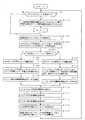
図3に、本発明の映像復号装置1が復号映像信号に対してH.264符号化情報フォーマットを重畳するために実行するフローチャートを図示する。 FIG. 3 shows a flowchart executed by the
次に、このフローチャートに従って、図1のように構成される本発明の映像復号装置1の実行する処理について説明する。 Next, processing executed by the
本発明の映像復号装置1は、復号対象のピクチャの復号処理に入ると、図3のフローチャートに示すように、先ず最初に、ステップS100で、全マクロブロックを処理したのか否かを判断して、全マクロブロックを処理していないことを判断するときには、ステップS101に進んで、処理対象のマクロブロックを選択する。 When the
続いて、ステップS102で、マクロブロック符号化データメモリ11から、処理対象のマクロブロックの符号化モードを読み込み、続くステップS103で、その読み込んだ符号化モードに従って、処理対象のマクロブロックがイントラ符号化されているのかインター符号化されているのかを判断する。 Subsequently, in step S102, the encoding mode of the processing target macroblock is read from the macroblock encoded
このステップS103の判断処理で、処理対象のマクロブロックがイントラ符号化されていることを判断するときには、ステップS104に進んで、図2に示す「マクロブロック・イントラ符号」にオンを書き込む。 If it is determined in step S103 that the macro block to be processed is intra-encoded, the process proceeds to step S104, and “ON” is written in the “macro block / intra code” shown in FIG.
続いて、ステップS105で、マクロブロック符号化データメモリ11から、イントラ予測サイズおよび予測方向の情報を読み込む。すなわち、処理対象のブロックがイントラ符号化されている場合には、H.264符号化情報の中に、イントラ予測サイズや予測方向の情報が記録されているので、それらの情報を読み込むのである。 Subsequently, in step S105, information on the intra prediction size and the prediction direction is read from the macroblock encoded
続いて、ステップS106で、読み込んだイントラ予測サイズおよび予測方向の情報に基づいて、イントラ用の切替解釈領域のデータを生成する。 Subsequently, in step S106, data of the switching interpretation area for intra is generated based on the read information of the intra prediction size and the prediction direction.
図4に、このときに生成するイントラ用の切替解釈領域のデータを図示する。 FIG. 4 shows data of the switching interpretation area for intra generated at this time.
この図4に示すように、イントラ予測サイズが4×4のブロックである場合には、16個のイントラ予測方向があるので、「イントラタイプ」の記述領域に4×4ブロック予測であることを示す“1”を書き込むとともに、16個用意される「イントラ予測モード[0] 〜[15]」に、16個の4×4ブロックのイントラ予測方向を書き込む。 As shown in FIG. 4, when the intra prediction size is a 4 × 4 block, there are 16 intra prediction directions. Therefore, it is determined that the 4 × 4 block prediction is in the “intra type” description area. In addition to writing “1”, 16 intra prediction directions of 4 × 4 blocks are written in 16 “intra prediction modes [0] to [15]”.
また、イントラ予測サイズが8×8のブロックである場合には、4個のイントラ予測方向があるので、「イントラタイプ」の記述領域に8×8ブロック予測であることを示す“2”を書き込むとともに、16個用意される「イントラ予測モード[0] 〜[15]」の内の4個の「イントラ予測モード[0] 〜[3] 」に、4個の8×8ブロックのイントラ予測方向を書き込む。 When the intra prediction size is an 8 × 8 block, there are four intra prediction directions, so “2” indicating 8 × 8 block prediction is written in the “intra type” description area. At the same time, four 8 × 8 block intra prediction directions are assigned to four “intra prediction modes [0] to [3]” of the 16 “intra prediction modes [0] to [15]”. Write.
また、イントラ予測サイズが16×16のブロックである場合には、1個のイントラ予測方向があるので、「イントラタイプ」の記述領域に8×8ブロック予測であることを示す“3”を書き込むとともに、16個用意される「イントラ予測モード[0] 〜[15]」の内の1個の「イントラ予測モード[0] 」に、1個の16×16ブロックのイントラ予測方向を書き込む。 In addition, when the intra prediction size is a 16 × 16 block, there is one intra prediction direction, so “3” indicating 8 × 8 block prediction is written in the “intra type” description area. At the same time, one 16 × 16 block intra prediction direction is written in one “intra prediction mode [0]” of the 16 “intra prediction modes [0] to [15]”.
このようにして、処理対象のマクロブロックがイントラ符号化された場合には、図2に示すH.264符号化情報フォーマットの持つ「切替解釈領域」に、イントラ符号化の全符号化情報を書き込むことができることになる。 In this way, when the macro block to be processed is intra-encoded, all intra-encoding information is written in the “switching interpretation area” of the H.264 encoding information format shown in FIG. Will be able to.
一方、ステップS103の判断処理で、処理対象のマクロブロックがインター符号化されていることを判断するときには、ステップS107に進んで、図2に示す「マクロブロック・イントラ符号」にオフを書き込む。 On the other hand, when it is determined in the determination process in step S103 that the macroblock to be processed is inter-encoded, the process proceeds to step S107, and “OFF” is written in the “macroblock intra code” shown in FIG.
続いて、ステップS108で、マクロブロック符号化データメモリ11から、インター予測サイズ、予測方向、参照画像番号および動きベクトルの情報を読み込む。すなわち、処理対象のブロックがインター符号化されている場合には、H.264符号化情報の中に、インター予測サイズや予測方向や参照画像番号や動きベクトルの情報が記録されているので、それらの情報を読み込むのである。 Subsequently, in step S108, information on the inter prediction size, the prediction direction, the reference image number, and the motion vector is read from the macroblock encoded
続いて、ステップS109で、読み込んだインター予測サイズに従って切替解釈領域のデータフォーマットを決定して、その決定したデータフォーマットに従って、切替解釈領域に、読み込んだ予測方向、参照画像番号および動きベクトルを書き込むことで、インター用の切替解釈領域のデータを生成する。 Subsequently, in step S109, the data format of the switching interpretation area is determined according to the read inter prediction size, and the read prediction direction, reference image number, and motion vector are written in the switching interpretation area according to the determined data format. Then, the data of the switching interpretation area for inter is generated.
図5および図6に、このときに生成するインター用の切替解釈領域のデータを図示する。 FIG. 5 and FIG. 6 show data of the switching interpretation area for inter generated at this time.
この図5に示すように、16×16ブロックでのインター符号化である場合、すなわち、図2の「ブロック分割単位フラグ」に“0”を書き込むとともに、「ブロックタイプ」の先頭2ビットに“00”を書き込む場合にあって、片方向予測の場合には、切替解釈領域Aのみを使用して、そこに図6(a)のデータフォーマットに従って動きベクトル・参照画像番号・予測方向を書き込み、双方向予測の場合には、切替解釈領域A,Bのみを使用して、そこに図6(a)のデータフォーマットに従って動きベクトル・参照画像番号・予測方向を書き込む。 As shown in FIG. 5, in the case of inter coding with 16 × 16 blocks, that is, “0” is written in the “block division unit flag” in FIG. In the case of writing 00 ″, in the case of unidirectional prediction, only the switching interpretation area A is used, and the motion vector, the reference image number, and the prediction direction are written therein according to the data format of FIG. In the case of bidirectional prediction, only the switching interpretation areas A and B are used, and a motion vector, a reference image number, and a prediction direction are written therein according to the data format of FIG.
また、水平16×垂直8の2ブロックあるいは水平8×垂直16の2ブロックでのインター符号化である場合、すなわち、図2の「ブロック分割単位フラグ」に“0”を書き込むとともに、「ブロックタイプ」の先頭2ビットに“01”あるいは“10”を書き込む場合にあって、片方向予測の場合には、切替解釈領域A,Bのみを使用して、そこに図6(a)のデータフォーマットに従って動きベクトル・参照画像番号・予測方向を書き込み、双方向予測の場合には、切替解釈領域A,B,C,Dを使用して、そこに図6(a)のデータフォーマットに従って動きベクトル・参照画像番号・予測方向を書き込む。 Further, in the case of inter coding with 2 blocks of horizontal 16 × vertical 8 or 2 blocks of horizontal 8 × vertical 16, that is, “0” is written in the “block division unit flag” of FIG. "01" or "10" is written in the first two bits of "", and in the case of unidirectional prediction, only the switching interpretation areas A and B are used, and the data format shown in FIG. The motion vector / reference image number / prediction direction is written according to FIG. 6B. In the case of bidirectional prediction, the switching interpretation areas A, B, C, and D are used, and the motion vector / Write the reference image number and prediction direction.
また、水平8×垂直8の4ブロックでのインター符号化である場合、すなわち、図2の「ブロック分割単位フラグ」に“1”を書き込むとともに、「ブロックタイプ」の先頭2ビットに“00”を書き込む場合にあって、片方向予測の場合には、切替解釈領域A,B,C,Dを使用して、そこに図6(a)のデータフォーマットに従って動きベクトル・参照画像番号・予測方向を書き込む。 Also, in the case of inter coding with 4 blocks of horizontal 8 × vertical 8, that is, “1” is written in the “block division unit flag” in FIG. 2 and “00” is added to the first 2 bits of “block type”. In the case of unidirectional prediction, the switching interpretation areas A, B, C, and D are used, and the motion vector, the reference image number, and the prediction direction according to the data format of FIG. Write.
また、水平8×垂直8の4ブロックでのインター符号化である場合、すなわち、図2の「ブロック分割単位フラグ」に“1”を書き込むとともに、「ブロックタイプ」の先頭2ビットに“00”を書き込む場合にあって、双方向予測の場合には、切替解釈領域A,B,C,Dを使用して、そこに図6(b)のデータフォーマットに従って動きベクトル・参照画像番号・予測方向を書き込む。このとき、動きベクトルの書込領域が小さなものになっているので、正確な動きベクトルを書き込むことができないので、LSB側の5ビットのみを書き込むことになる。 Also, in the case of inter coding with 4 blocks of horizontal 8 × vertical 8, that is, “1” is written in the “block division unit flag” in FIG. 2 and “00” is added to the first 2 bits of “block type”. In the case of bidirectional prediction, the switching interpretation areas A, B, C, and D are used, and the motion vector, reference image number, and prediction direction are used in accordance with the data format of FIG. Write. At this time, since the motion vector writing area is small, an accurate motion vector cannot be written, so only the 5 bits on the LSB side are written.
また、水平8×垂直8よりも細かいブロックでのインター符号化である場合、すなわち、図2の「ブロック分割単位フラグ」に“1”を書き込むとともに、「ブロックタイプ」の先頭2ビットに“00”以外の値を書き込む場合には、動きベクトルの個数が多くなっていることで、切替解釈領域A,B,C,Dに動きベクトルを書き込むことはできないので、切替解釈領域A,B,C,Dを使用して、そこに図6(c)のデータフォーマットに従って参照画像番号・予測方向を書き込む。 Further, in the case of inter coding with a block smaller than horizontal 8 × vertical 8, that is, “1” is written to the “block division unit flag” in FIG. 2 and “00” is added to the first 2 bits of “block type”. When a value other than “” is written, the motion vector cannot be written in the switching interpretation areas A, B, C, and D because the number of motion vectors is large. , D are used to write the reference image number / prediction direction in accordance with the data format of FIG.
このようにして、処理対象のマクロブロックがインター符号化された場合には、図2に示すH.264符号化情報フォーマットの持つ「切替解釈領域」に、インター符号化の符号化情報の全てを書き込むことができない場合があるので、そのような場合には、可能な限り書き込むという形態に従ってインター符号化の符号化情報を書き込むようにするのである。 In this way, when the macroblock to be processed is inter-encoded, all the inter-encoded information is stored in the “switching interpretation area” of the H.264 encoded information format shown in FIG. Since there is a case where writing cannot be performed, in such a case, coding information of inter coding is written in accordance with a form of writing as much as possible.
ステップS106でイントラ用の切替解釈領域のデータを生成し、あるいは、ステップS109でインター用の切替解釈領域のデータを生成すると、続いて、ステップS110で、その生成した切替解釈領域のデータと、マクロブロック符号化データメモリ11から取得できる処理対象のマクロブロックに固有の情報とに基づいて、図2に示すH.264符号化情報フォーマットに記述する処理対象のマクロブロックについての符号化情報部分であるマクロブロック符号化情報を生成する。 In step S106, the switching interpretation area data for intra is generated, or the switching interpretation area data for inter is generated in step S109. Subsequently, in step S110, the generated switching interpretation area data and macro are generated. This is an encoding information portion for a processing target macroblock described in the H.264 encoding information format shown in FIG. 2 based on information specific to the processing target macroblock that can be acquired from the block encoded
続いて、ステップS111で、処理対象のマクロブロックの復号情報からスライス符号化情報を取得して、その中から一部分を抽出し、その抽出したスライス符号化情報部分に従って、図2に示すH.264符号化情報フォーマットに記述するスライス符号化情報を生成する。 Subsequently, in step S111, slice coding information is acquired from the decoding information of the macroblock to be processed, a part is extracted from the obtained information, and the H.264 shown in FIG. Slice coding information described in the coding information format is generated.
続いて、ステップS112で、処理対象のマクロブロックの復号情報からピクチャ符号化情報を取得して、その中から一部分を抽出し、その抽出したピクチャ符号化情報部分に従って、図2に示すH.264符号化情報フォーマットに記述するピクチャ符号化情報を生成する。 Subsequently, in step S112, picture coding information is acquired from the decoding information of the macroblock to be processed, and a part thereof is extracted, and according to the extracted picture coding information part, H.264 shown in FIG. Picture coding information described in the coding information format is generated.
続いて、ステップS113で、生成したマクロブロック符号化情報と、生成したスライス符号化情報と、生成したピクチャ符号化情報とを統合することで、図2に示すH.264符号化情報フォーマットを生成する。 Subsequently, in step S113, the generated macroblock encoded information, the generated slice encoded information, and the generated picture encoded information are integrated to generate the H.264 encoded information format shown in FIG. To do.
続いて、ステップS114で、処理対象のマクロブロックの復号画像のLSBのプレーンに、生成したH.264符号化情報フォーマットを重畳してから、ステップS100の処理に戻る。 Subsequently, in step S114, the generated H.264 encoded information format is superimposed on the LSB plane of the decoded image of the macroblock to be processed, and then the process returns to step S100.
そして、ステップS100〜ステップS114の処理を繰り返していくことで、ステップS100で、全マクロブロックを処理したことを判断すると、ステップS115に進んで、H.264符号化情報の重畳されたマクロブロック復号画像を合成することで復号画像を生成してそれを出力することで、H.264符号化情報の重畳された映像信号を生成して出力することになる。 If it is determined in step S100 that all macroblocks have been processed by repeating the processes in steps S100 to S114, the process proceeds to step S115, and the macroblock decoding with the H.264 encoded information superimposed is performed. By synthesizing the images, a decoded image is generated and output, so that a video signal on which H.264 encoded information is superimposed is generated and output.
このようにして、本発明の映像復号装置1では、H.264で符号化された際に発生するデータ量の大きな符号化情報を、MPEG2と同様のモールフォーマットでもって復号映像信号と一緒に伝送するように処理するのである。 In this way, in the
本発明は、イントラ符号化及びインター符号化により生成された映像符号化データを復号することで得た復号映像信号を再符号化する場合に適用できるものであり、H.264などで符号化された際に発生するデータ量の大きな符号化情報を、MPEG2と同様のモールフォーマットでもって復号映像信号と一緒に伝送できるようにすることを実現する。 The present invention is applicable when re-encoding a decoded video signal obtained by decoding video encoded data generated by intra encoding and inter encoding, and is encoded with H.264 or the like. It is possible to transmit encoded information having a large amount of data generated at the same time together with the decoded video signal in the same format as MPEG2.
1 映像復号装置
10 ピクチャ復号部
11 マクロブロック符号化データメモリ
12 イントラ・マクロブロック用切替解釈領域生成部
13 インター・マクロブロック用切替解釈領域生成部
14 切替スイッチ
15 マクロブロック符号化情報生成部
16 スライス符号化情報生成部
17 ピクチャ符号化情報生成部
18 H.264符号化情報フォーマット生成部
19 ベースバンド映像LSB重畳部
20 フレームメモリ
120 イントラ予測サイズ値設定部
121 予測方向設定部
130 インター予測サイズ値設定部
131 参照画像番号設定部
132 動きベクトル設定部DESCRIPTION OF
Claims (10)
Translated fromJapanese前記ビットストリームに含まれる復号対象ブロックについての符号化情報を復号する復号手段と、
前記符号化情報に基づいて、復号対象ブロックと同じ大きさを持つ1ビットプレーン上の規定のビット位置に、それぞれ規定されたビット長の、同期用固定符号領域と、復号対象ブロック巡回番号領域と、ピクチャ符号化情報記述領域と、スライス符号化情報記述領域と、スライスタイプ領域と、復号対象ブロック・イントラ符号領域と、ブロック分割単位フラグ領域と、ブロックタイプ領域とからなる共通領域、および、前記復号対象ブロック・イントラ符号領域の情報がイントラ符号化を示している場合とインター符号化を示している場合とで異なるデータフォーマットの符号化情報が記述される規定されたビット長の切替解釈領域を有する符号化情報フォーマットに従って、前記同期用固定符号領域に、所定値の同期用固定符号を書き込み、前記復号対象ブロック巡回番号領域に、画面内における復号対象ブロックの位置を示す復号対象ブロック巡回番号を書き込み、前記ピクチャ符号化情報記述領域に、復号対象ブロックに割り付けられたピクチャ符号化情報を書き込み、前記スライス符号化情報記述領域に、復号対象ブロックに割り付けられたスライス符号化情報を書き込み、前記スライスタイプ領域に、復号対象ブロックのスライス符号化タイプを書き込み、前記復号対象ブロック・イントラ符号領域に、復号対象ブロックがイントラで符号化されたのかインターで符号化されたのかを示すフラグ値を書き込み、前記ブロック分割単位フラグ領域および前記ブロックタイプ領域に、復号対象ブロックの符号化分割形態を示す情報を書き込み、さらに、前記切替解釈領域に、復号対象ブロックがイントラ符号化で符号化された場合にはイントラ符号化に合わせたデータフォーマットに従ってイントラ符号化の符号化情報を書き込み、インター符号化で符号化された場合にはインター符号化に合わせたデータフォーマットに従ってインター符号化の符号化情報を書き込む書込手段と、
前記1ビットプレーンと復号対象ブロックの復号画像とを重畳することで映像信号を生成する生成手段とを備えることを、
特徴とする映像信号生成装置。A video signal generation device that receives a bit stream of video encoded data generated by intra coding and inter coding as input, decodes the bit stream in units of a predetermined size block, and generates a video signal. There,
Decoding means for decoding encoded information about a decoding target block included in the bitstream;
Based on the coding information, afixed bit area for synchronization having a prescribed bit length at a prescribed bit position on a 1-bit plane having the same size asthe decoding target block, a decoding target block cyclic number area, and A common area composed of a picture coding information description area, a slice coding information description area, a slice type area, a decoding target block / intra code area, a block division unit flag area, and a block type area, and A switching interpretation area having a prescribed bit length in which encoding information of different data formats is described when the information of the block to be decoded / intra code area indicates intra encoding and when the information indicates inter encoding. In accordance with the encoding information format possessed, a predetermined fixed synchronous code is written in the synchronous fixed code area. The decoding target block cyclic number indicating the position of the decoding target block in the screen is written in the decoding target block cyclic number area, and the picture coding information assigned to the decoding target block is written in the picture coding information description area. Writing, writing the slice coding information allocated to the decoding target block in the slice coding information description area, writing the slice coding type of the decoding target block in the slice type area, and the decoding target block / intra code area In addition, a flag value indicating whether the decoding target block is encoded intra or inter is written, and the coding division form of the decoding target block is indicated in the block division unit flag area and the block type area. writes information, further,the switching interpreted region Writes the coding informationof the intra-coded according to a data format matching the intra-coding if the decoding target block has been coded by intra-coding, the inter-coding when it is coded in inter coding Writing means for writinginter-coded coding information according to the combined data format;
Generating means for generating a video signal by superimposing the 1-bit plane and a decoded image of a decoding target block;
A featured video signal generator.
前記ビットストリームに含まれる復号対象ブロックについての符号化情報を復号する復号手段と、
前記符号化情報に基づいて、復号対象ブロックと同じ大きさを持つ1ビットプレーン上の規定のビット位置に、それぞれ規定されたビット長の、同期用固定符号領域と、復号対象ブロック巡回番号領域と、ピクチャ符号化情報記述領域と、スライス符号化情報記述領域と、スライスタイプ領域と、復号対象ブロック・イントラ符号領域と、ブロック分割単位フラグ領域と、ブロックタイプ領域と、双方向予測フラグ領域とからなる共通領域、および、前記復号対象ブロック・イントラ符号領域の情報がイントラ符号化を示している場合とインター符号化を示している場合とで異なるデータフォーマットの符号化情報が記述される規定されたビット長の切替解釈領域を有する符号化情報フォーマットに従って、前記同期用固定符号領域に、所定値の同期用固定符号を書き込み、前記復号対象ブロック巡回番号領域に、画面内における復号対象ブロックの位置を示す復号対象ブロック巡回番号を書き込み、前記ピクチャ符号化情報記述領域に、復号対象ブロックに割り付けられたピクチャ符号化情報を書き込み、前記スライス符号化情報記述領域に、復号対象ブロックに割り付けられたスライス符号化情報を書き込み、前記スライスタイプ領域に、復号対象ブロックのスライス符号化タイプを書き込み、前記復号対象ブロック・イントラ符号領域に、復号対象ブロックがイントラで符号化されたのかインターで符号化されたのかを示すフラグ値を書き込み、前記ブロック分割単位フラグ領域および前記ブロックタイプ領域に、復号対象ブロックの符号化分割形態を示す情報を書き込み、前記双方向予測フラグ領域に、復号対象ブロックまたはそのサブブロックについて、双方向予測で符号化されたのか片方向予測で符号化されたのかを示す情報を書き込み、さらに、前記切替解釈領域に、復号対象ブロックがイントラ符号化で符号化された場合にはイントラ符号化に合わせたデータフォーマットに従ってイントラ符号化の符号化情報を書き込み、インター符号化で符号化された場合にはインター符号化に合わせたデータフォーマットに従ってインター符号化の符号化情報を書き込む書込手段と、
前記1ビットプレーンと復号対象ブロックの復号画像とを重畳することで映像信号を生成する生成手段とを備えることを、
特徴とする映像信号生成装置。A video signal generation device that receives a bit stream of video encoded data generated by intra coding and inter coding as input, decodes the bit stream in units of a predetermined size block, and generates a video signal. There,
Decoding means for decoding encoded information about a decoding target block included in the bitstream;
Based on the coding information, afixed bit area for synchronization having a prescribed bit length at a prescribed bit position on a 1-bit plane having the same size asthe decoding target block, a decoding target block cyclic number area, and , A picture coding information description area, a slice coding information description area, a slice type area, a decoding target block / intra code area, a block division unit flag area, a block type area, and a bidirectional prediction flag area And coding information of different data formats is described in the case where the information of the decoding target block / intra code area indicates intra coding and the case of indicating inter coding. In accordance with the encoding information format having a bit length switching interpretation area, the synchronization fixed code area has a predetermined The synchronization fixed code is written, the decoding target block cyclic number indicating the position of the decoding target block in the screen is written in the decoding target block cyclic number area, and assigned to the decoding target block in the picture coding information description area The coded coding information is written, the slice coded information assigned to the decoding target block is written in the slice coding information description area, the slice coding type of the decoding target block is written in the slice type area, and the decoding is performed. A flag value indicating whether the decoding target block is encoded intra or inter is written in the target block / intra code area, and the decoding target block of the decoding target block is written in the block division unit flag area and the block type area. Write information indicating the coding division form, A serial bidirectional prediction flag area, the current block or sub-block, writes information indicating whether the encoded with the one-way prediction encoded in the bidirectional prediction, further tothe switch interpretation area, decoding When the target block is coded byintra coding, the coding information ofintra coding is written according to the data format adapted tointra coding, and when coded by inter coding, it is matched with inter coding. Writing means for writinginter-coded coding information according to the data format;
Comprising a generating means for generating a video signal by superimposing the 1-bit plane and a decoded image of a decoding target block,
A featured video signal generator.
前記書込手段は、復号対象ブロックの符号化分割形態に応じて前記符号化情報のデータ量が大きくなることで、前記符号化情報が前記切替解釈領域に収まらない場合には、その符号化分割形態に合わせたデータフォーマットに従って、前記符号化情報の一部を省略した形で前記切替解釈領域に書き込むことを、
特徴とする映像信号生成装置。The video signal generation device according to claim 1or 2 ,
When the coding information does not fit in the switching interpretation area due to an increase in the data amount of the coding information according to the coding division form of the block to be decoded, the writing means performs the coding division. According to the data format according to the form, writing in the switching interpretation area in a form omitting a part of the encoding information,
A featured video signal generator.
前記書込手段は、前記ピクチャ符号化情報記述領域に、復号対象ブロックが属するピクチャについての符号化情報の一部を書き込むことを、
特徴とする映像信号生成装置。In the video signal generating device according toany one of claims 1to 3 ,
The writing means writes in thepicture coding information description area a part of coding information for a picture towhich a decoding target block belongs;
A featured video signal generator.
前記ビットストリームに含まれる復号対象ブロックについての符号化情報を復号する過程と、
前記符号化情報に基づいて、復号対象ブロックと同じ大きさを持つ1ビットプレーン上の規定のビット位置に、それぞれ規定されたビット長の、同期用固定符号領域と、復号対象ブロック巡回番号領域と、ピクチャ符号化情報記述領域と、スライス符号化情報記述領域と、スライスタイプ領域と、復号対象ブロック・イントラ符号領域と、ブロック分割単位フラグ領域と、ブロックタイプ領域とからなる共通領域、および、前記復号対象ブロック・イントラ符号領域の情報がイントラ符号化を示している場合とインター符号化を示している場合とで異なるデータフォーマットの符号化情報が記述される規定されたビット長の切替解釈領域を有する符号化情報フォーマットに従って、前記同期用固定符号領域に、所定値の同期用固定符号を書き込み、前記復号対象ブロック巡回番号領域に、画面内における復号対象ブロックの位置を示す復号対象ブロック巡回番号を書き込み、前記ピクチャ符号化情報記述領域に、復号対象ブロックに割り付けられたピクチャ符号化情報を書き込み、前記スライス符号化情報記述領域に、復号対象ブロックに割り付けられたスライス符号化情報を書き込み、前記スライスタイプ領域に、復号対象ブロックのスライス符号化タイプを書き込み、前記復号対象ブロック・イントラ符号領域に、復号対象ブロックがイントラで符号化されたのかインターで符号化されたのかを示すフラグ値を書き込み、前記ブロック分割単位フラグ領域および前記ブロックタイプ領域に、復号対象ブロックの符号化分割形態を示す情報を書き込み、さらに、前記切替解釈領域に、復号対象ブロックがイントラ符号化で符号化された場合にはイントラ符号化に合わせたデータフォーマットに従ってイントラ符号化の符号化情報を書き込み、インター符号化で符号化された場合にはインター符号化に合わせたデータフォーマットに従ってインター符号化の符号化情報を書き込む過程と、
前記1ビットプレーンと復号対象ブロックの復号画像とを重畳することで映像信号を生成する過程とを備えることを、
特徴とする映像信号生成方法。A video signal generation method in which a bit stream of video encoded data generated by intra coding and inter coding is input, and the bit stream is decoded in units of a predetermined size block to generate a video signal. There,
A process of decoding encoded information about a decoding target block included in the bitstream;
Based on the coding information, afixed bit area for synchronization having a prescribed bit length at a prescribed bit position on a 1-bit plane having the same size asthe decoding target block, a decoding target block cyclic number area, and A common area composed of a picture coding information description area, a slice coding information description area, a slice type area, a decoding target block / intra code area, a block division unit flag area, and a block type area, and A switching interpretation area having a prescribed bit length in which encoding information of different data formats is described when the information of the block to be decoded / intra code area indicates intra encoding and when the information indicates inter encoding. In accordance with the encoding information format possessed, a predetermined fixed synchronous code is written in the synchronous fixed code area. The decoding target block cyclic number indicating the position of the decoding target block in the screen is written in the decoding target block cyclic number area, and the picture coding information assigned to the decoding target block is written in the picture coding information description area. Writing, writing the slice coding information allocated to the decoding target block in the slice coding information description area, writing the slice coding type of the decoding target block in the slice type area, and the decoding target block / intra code area In addition, a flag value indicating whether the decoding target block is encoded intra or inter is written, and the coding division form of the decoding target block is indicated in the block division unit flag area and the block type area. writes information, further,the switching interpreted region Writes the coding informationof the intra-coded according to a data format matching the intra-coding if the decoding target block has been coded by intra-coding, the inter-coding when it is coded in inter coding Writinginter-coded information according to the combined data format;
A process of generating a video signal by superimposing the 1-bit plane and a decoded image of a decoding target block,
A characteristic video signal generation method.
前記ビットストリームに含まれる復号対象ブロックについての符号化情報を復号する過程と、
前記符号化情報に基づいて、復号対象ブロックと同じ大きさを持つ1ビットプレーン上の規定のビット位置に、それぞれ規定されたビット長の、同期用固定符号領域と、復号対象ブロック巡回番号領域と、ピクチャ符号化情報記述領域と、スライス符号化情報記述領域と、スライスタイプ領域と、復号対象ブロック・イントラ符号領域と、ブロック分割単位フラグ領域と、ブロックタイプ領域と、双方向予測フラグ領域とからなる共通領域、および、前記復号対象ブロック・イントラ符号領域の情報がイントラ符号化を示している場合とインター符号化を示している場合とで異なるデータフォーマットの符号化情報が記述される規定されたビット長の切替解釈領域を有する符号化情報フォーマットに従って、前記同期用固定符号領域に、所定値の同期用固定符号を書き込み、前記復号対象ブロック巡回番号領域に、画面内における復号対象ブロックの位置を示す復号対象ブロック巡回番号を書き込み、前記ピクチャ符号化情報記述領域に、復号対象ブロックに割り付けられたピクチャ符号化情報を書き込み、前記スライス符号化情報記述領域に、復号対象ブロックに割り付けられたスライス符号化情報を書き込み、前記スライスタイプ領域に、復号対象ブロックのスライス符号化タイプを書き込み、前記復号対象ブロック・イントラ符号領域に、復号対象ブロックがイントラで符号化されたのかインターで符号化されたのかを示すフラグ値を書き込み、前記ブロック分割単位フラグ領域および前記ブロックタイプ領域に、復号対象ブロックの符号化分割形態を示す情報を書き込み、前記双方向予測フラグ領域に、復号対象ブロックまたはそのサブブロックについて、双方向予測で符号化されたのか片方向予測で符号化されたのかを示す情報を書き込み、さらに、前記切替解釈領域に、復号対象ブロックがイントラ符号化で符号化された場合にはイントラ符号化に合わせたデータフォーマットに従ってイントラ符号化の符号化情報を書き込み、インター符号化で符号化された場合にはインター符号化に合わせたデータフォーマットに従ってインター符号化の符号化情報を書き込む過程と、
前記1ビットプレーンと復号対象ブロックの復号画像とを重畳することで映像信号を生成する過程とを備えることを、
特徴とする映像信号生成方法。A video signal generation method in which a bit stream of video encoded data generated by intra coding and inter coding is input, and the bit stream is decoded in units of a predetermined size block to generate a video signal. There,
A process of decoding encoded information about a decoding target block included in the bitstream;
Based on the coding information, afixed bit area for synchronization having a prescribed bit length at a prescribed bit position on a 1-bit plane having the same size asthe decoding target block, a decoding target block cyclic number area, and , A picture coding information description area, a slice coding information description area, a slice type area, a decoding target block / intra code area, a block division unit flag area, a block type area, and a bidirectional prediction flag area And coding information of different data formats is described in the case where the information of the decoding target block / intra code area indicates intra coding and the case of indicating inter coding. In accordance with the encoding information format having a bit length switching interpretation area, the synchronization fixed code area has a predetermined The synchronization fixed code is written, the decoding target block cyclic number indicating the position of the decoding target block in the screen is written in the decoding target block cyclic number area, and assigned to the decoding target block in the picture coding information description area The coded coding information is written, the slice coded information assigned to the decoding target block is written in the slice coding information description area, the slice coding type of the decoding target block is written in the slice type area, and the decoding is performed. A flag value indicating whether the decoding target block is encoded intra or inter is written in the target block / intra code area, and the decoding target block of the decoding target block is written in the block division unit flag area and the block type area. Write information indicating the coding division form, A serial bidirectional prediction flag area, the current block or sub-block, writes information indicating whether the encoded with the one-way prediction encoded in the bidirectional prediction, further tothe switch interpretation area, decoding When the target block is coded byintra coding, the coding information ofintra coding is written according to the data format adapted tointra coding, and when coded by inter coding, it is matched with inter coding. Writinginter-coded information according to the data format;
A process of generating a video signal by superimposing the 1-bit plane and a decoded image of a decoding target block,
A characteristic video signal generation method.
前記書き込む過程では、復号対象ブロックの符号化分割形態に応じて前記符号化情報のデータ量が大きくなることで、前記符号化情報が前記切替解釈領域に収まらない場合には、その符号化分割形態に合わせたデータフォーマットに従って、前記符号化情報の一部を省略した形で前記切替解釈領域に書き込むことを、
特徴とする映像信号生成方法。The video signal generation method according to claim5 or 6 ,
In the writing process, if the encoded information does not fit in the switching interpretation area due to an increase in the data amount of the encoded information according to the encoded division form of the decoding target block, the encoded division form According to the data format tailored to, writing in the switching interpretation area in a form omitting a part of the encoding information,
A characteristic video signal generation method.
前記書き込む過程では、前記ピクチャ符号化情報記述領域に、復号対象ブロックが属するピクチャについての符号化情報の一部を書き込むことを、
特徴とする映像信号生成方法。In the video signal generation method according toany one of claims5 to 7 ,
In the writing process, writing a part of the coding information about the picture to which the block to be decoded belongsinto the picture coding information description area ,
A characteristic video signal generation method.
Priority Applications (6)
| Application Number | Priority Date | Filing Date | Title |
|---|---|---|---|
| JP2007219199AJP4739295B2 (en) | 2007-08-27 | 2007-08-27 | VIDEO SIGNAL GENERATION DEVICE, VIDEO SIGNAL GENERATION METHOD, VIDEO SIGNAL GENERATION PROGRAM, AND COMPUTER-READABLE RECORDING MEDIUM CONTAINING THE PROGRAM |
| EP08828861AEP2182733A4 (en) | 2007-08-27 | 2008-08-27 | Video signal generating device, video signal generating method, video signal generating program and computer readable recording medium on which the program is recorded |
| KR1020107002724AKR101140269B1 (en) | 2007-08-27 | 2008-08-27 | Video signal generating device, video signal generating method, video signal generating program and computer readable recording medium on which the program is recorded |
| US12/673,095US8902981B2 (en) | 2007-08-27 | 2008-08-27 | Video signal generation apparatus, video signal generation method, video signal generation program, and computer readable recording medium recording the program |
| CN2008801030609ACN101779470B (en) | 2007-08-27 | 2008-08-27 | Video signal generating device, and video signal generating method |
| PCT/JP2008/065295WO2009028549A1 (en) | 2007-08-27 | 2008-08-27 | Video signal generating device, video signal generating method, video signal generating program and computer readable recording medium on which the program is recorded |
Applications Claiming Priority (1)
| Application Number | Priority Date | Filing Date | Title |
|---|---|---|---|
| JP2007219199AJP4739295B2 (en) | 2007-08-27 | 2007-08-27 | VIDEO SIGNAL GENERATION DEVICE, VIDEO SIGNAL GENERATION METHOD, VIDEO SIGNAL GENERATION PROGRAM, AND COMPUTER-READABLE RECORDING MEDIUM CONTAINING THE PROGRAM |
Publications (2)
| Publication Number | Publication Date |
|---|---|
| JP2009055259A JP2009055259A (en) | 2009-03-12 |
| JP4739295B2true JP4739295B2 (en) | 2011-08-03 |
Family
ID=40387267
Family Applications (1)
| Application Number | Title | Priority Date | Filing Date |
|---|---|---|---|
| JP2007219199AActiveJP4739295B2 (en) | 2007-08-27 | 2007-08-27 | VIDEO SIGNAL GENERATION DEVICE, VIDEO SIGNAL GENERATION METHOD, VIDEO SIGNAL GENERATION PROGRAM, AND COMPUTER-READABLE RECORDING MEDIUM CONTAINING THE PROGRAM |
Country Status (6)
| Country | Link |
|---|---|
| US (1) | US8902981B2 (en) |
| EP (1) | EP2182733A4 (en) |
| JP (1) | JP4739295B2 (en) |
| KR (1) | KR101140269B1 (en) |
| CN (1) | CN101779470B (en) |
| WO (1) | WO2009028549A1 (en) |
Families Citing this family (7)
| Publication number | Priority date | Publication date | Assignee | Title |
|---|---|---|---|---|
| US8769612B2 (en) | 2008-08-14 | 2014-07-01 | Microsoft Corporation | Portable device association |
| US8943551B2 (en) | 2008-08-14 | 2015-01-27 | Microsoft Corporation | Cloud-based device information storage |
| KR20120035096A (en)* | 2010-10-04 | 2012-04-13 | 한국전자통신연구원 | A method and apparatus of side information signaling for quadtree transform |
| JP5649523B2 (en)* | 2011-06-27 | 2015-01-07 | 日本電信電話株式会社 | Video encoding method, apparatus, video decoding method, apparatus, and program thereof |
| US9032106B2 (en) | 2013-05-29 | 2015-05-12 | Microsoft Technology Licensing, Llc | Synchronizing device association data among computing devices |
| KR102821962B1 (en) | 2016-08-22 | 2025-06-20 | 코닌클리케 필립스 엔.브이. | Method and apparatus to transmite the block-partiton information for codec of cctv camera |
| CN110166824B (en)* | 2019-06-24 | 2021-07-06 | 湖南国科微电子股份有限公司 | Live television channel switching method and system based on set top box |
Family Cites Families (13)
| Publication number | Priority date | Publication date | Assignee | Title |
|---|---|---|---|---|
| EP2271103A3 (en)* | 1996-07-15 | 2013-01-16 | Amstr. Investments 4 K.G., LLC | Video Signal Compression |
| US7236526B1 (en)* | 1999-02-09 | 2007-06-26 | Sony Corporation | Coding system and its method, coding device and its method, decoding device and its method, recording device and its method, and reproducing device and its method |
| GB9920929D0 (en)* | 1999-09-03 | 1999-11-10 | Sony Uk Ltd | Video signal processor |
| JP4193162B2 (en)* | 2000-11-29 | 2008-12-10 | 日本ビクター株式会社 | Image signal encoding device |
| US7310371B2 (en)* | 2003-05-30 | 2007-12-18 | Lsi Corporation | Method and/or apparatus for reducing the complexity of H.264 B-frame encoding using selective reconstruction |
| JP4877449B2 (en)* | 2004-11-04 | 2012-02-15 | カシオ計算機株式会社 | Moving picture coding apparatus and moving picture coding processing program |
| US20080123947A1 (en)* | 2005-07-22 | 2008-05-29 | Mitsubishi Electric Corporation | Image encoding device, image decoding device, image encoding method, image decoding method, image encoding program, image decoding program, computer readable recording medium having image encoding program recorded therein |
| JP4666255B2 (en)* | 2005-12-27 | 2011-04-06 | 日本電気株式会社 | Encoded data selection, encoded data setting, re-encoded data generation and re-encoding method and apparatus |
| KR100949981B1 (en)* | 2006-03-30 | 2010-03-29 | 엘지전자 주식회사 | A method and apparatus for decoding/encoding a video signal |
| GB2438004B (en)* | 2006-05-08 | 2011-08-24 | Snell & Wilcox Ltd | Creation and compression of video data |
| US8532178B2 (en)* | 2006-08-25 | 2013-09-10 | Lg Electronics Inc. | Method and apparatus for decoding/encoding a video signal with inter-view reference picture list construction |
| US8312558B2 (en)* | 2007-01-03 | 2012-11-13 | At&T Intellectual Property I, L.P. | System and method of managing protected video content |
| JP5050637B2 (en)* | 2007-05-11 | 2012-10-17 | ソニー株式会社 | VIDEO SIGNAL PROCESSING DEVICE, VIDEO SIGNAL PROCESSING METHOD, VIDEO SIGNAL PROCESSING METHOD PROGRAM, AND RECORDING MEDIUM CONTAINING VIDEO SIGNAL PROCESSING METHOD PROGRAM |
- 2007
- 2007-08-27JPJP2007219199Apatent/JP4739295B2/enactiveActive
- 2008
- 2008-08-27EPEP08828861Apatent/EP2182733A4/ennot_activeCeased
- 2008-08-27KRKR1020107002724Apatent/KR101140269B1/enactiveActive
- 2008-08-27USUS12/673,095patent/US8902981B2/enactiveActive
- 2008-08-27WOPCT/JP2008/065295patent/WO2009028549A1/enactiveApplication Filing
- 2008-08-27CNCN2008801030609Apatent/CN101779470B/enactiveActive
Also Published As
| Publication number | Publication date |
|---|---|
| CN101779470A (en) | 2010-07-14 |
| KR20100030671A (en) | 2010-03-18 |
| EP2182733A1 (en) | 2010-05-05 |
| CN101779470B (en) | 2013-01-16 |
| KR101140269B1 (en) | 2012-04-26 |
| EP2182733A4 (en) | 2010-10-06 |
| JP2009055259A (en) | 2009-03-12 |
| US8902981B2 (en) | 2014-12-02 |
| WO2009028549A1 (en) | 2009-03-05 |
| US20110122948A1 (en) | 2011-05-26 |
Similar Documents
| Publication | Publication Date | Title |
|---|---|---|
| JP6070870B2 (en) | Image processing apparatus, image processing method, program, and recording medium | |
| JP4739295B2 (en) | VIDEO SIGNAL GENERATION DEVICE, VIDEO SIGNAL GENERATION METHOD, VIDEO SIGNAL GENERATION PROGRAM, AND COMPUTER-READABLE RECORDING MEDIUM CONTAINING THE PROGRAM | |
| CN101822046B (en) | Method and apparatus for creating an encoded output video stream from at least two encoded input video streams | |
| JP4991699B2 (en) | Scalable encoding and decoding methods for video signals | |
| CN112740696B (en) | Video encoding and decoding | |
| CN106878708B (en) | Video encoding device and decoding device, video encoding method and decoding method | |
| JP2010166133A (en) | Moving picture coding apparatus | |
| CN103329534A (en) | Image encoding device and image decoding device | |
| JP7415030B2 (en) | Image encoding/decoding method and apparatus based on mixed NAL unit types and method for transmitting bitstreams | |
| JP2001285876A (en) | Image encoding device, its method, video camera, image recording device and image transmitting device | |
| JP4666255B2 (en) | Encoded data selection, encoded data setting, re-encoded data generation and re-encoding method and apparatus | |
| CN101459851B (en) | Exchange Method of Compressed Video Data Stream | |
| JP2020108032A (en) | Video code stream editing device and program | |
| Carreira et al. | Error concealment-aware encoding for robust video transmission | |
| JP2006203661A (en) | Moving picture coding apparatus, moving picture decoding apparatus, and coded stream generation method | |
| CN101188768A (en) | Method and device for sending and receiving moving images based on RGB codec | |
| JP2009071365A (en) | Moving picture decoder and decoding method | |
| CN112887737B (en) | Conditional parse extension syntax for HEVC extension processing | |
| JP2007020002A (en) | Video encoding device | |
| JP5421739B2 (en) | Moving picture coding apparatus, moving picture decoding apparatus, and moving picture coding method | |
| JP4193162B2 (en) | Image signal encoding device | |
| JP5061355B2 (en) | Image encoding method, apparatus and program, and image processing apparatus | |
| JP4676474B2 (en) | Image coding method | |
| JP2012060423A (en) | Video encoder | |
| KR20130119717A (en) | Apparatus and method of efficient video coding using auxiliary motion vectors |
Legal Events
| Date | Code | Title | Description |
|---|---|---|---|
| RD04 | Notification of resignation of power of attorney | Free format text:JAPANESE INTERMEDIATE CODE: A7424 Effective date:20100331 | |
| A131 | Notification of reasons for refusal | Free format text:JAPANESE INTERMEDIATE CODE: A131 Effective date:20101221 | |
| A521 | Request for written amendment filed | Free format text:JAPANESE INTERMEDIATE CODE: A523 Effective date:20110221 | |
| TRDD | Decision of grant or rejection written | ||
| A01 | Written decision to grant a patent or to grant a registration (utility model) | Free format text:JAPANESE INTERMEDIATE CODE: A01 Effective date:20110426 | |
| A01 | Written decision to grant a patent or to grant a registration (utility model) | Free format text:JAPANESE INTERMEDIATE CODE: A01 | |
| A61 | First payment of annual fees (during grant procedure) | Free format text:JAPANESE INTERMEDIATE CODE: A61 Effective date:20110427 | |
| R150 | Certificate of patent or registration of utility model | Free format text:JAPANESE INTERMEDIATE CODE: R150 Ref document number:4739295 Country of ref document:JP Free format text:JAPANESE INTERMEDIATE CODE: R150 | |
| FPAY | Renewal fee payment (event date is renewal date of database) | Free format text:PAYMENT UNTIL: 20140513 Year of fee payment:3 | |
| S531 | Written request for registration of change of domicile | Free format text:JAPANESE INTERMEDIATE CODE: R313531 | |
| R350 | Written notification of registration of transfer | Free format text:JAPANESE INTERMEDIATE CODE: R350 | |
| S533 | Written request for registration of change of name | Free format text:JAPANESE INTERMEDIATE CODE: R313533 | |
| R360 | Written notification for declining of transfer of rights | Free format text:JAPANESE INTERMEDIATE CODE: R360 |