JP4738948B2 - Information processing apparatus, image processing method, and computer program - Google Patents
Information processing apparatus, image processing method, and computer programDownload PDFInfo
- Publication number
- JP4738948B2 JP4738948B2JP2005265908AJP2005265908AJP4738948B2JP 4738948 B2JP4738948 B2JP 4738948B2JP 2005265908 AJP2005265908 AJP 2005265908AJP 2005265908 AJP2005265908 AJP 2005265908AJP 4738948 B2JP4738948 B2JP 4738948B2
- Authority
- JP
- Japan
- Prior art keywords
- processing
- data
- output
- print command
- Prior art date
- Legal status (The legal status is an assumption and is not a legal conclusion. Google has not performed a legal analysis and makes no representation as to the accuracy of the status listed.)
- Expired - Fee Related
Links
Images


Classifications
- G—PHYSICS
- G06—COMPUTING OR CALCULATING; COUNTING
- G06F—ELECTRIC DIGITAL DATA PROCESSING
- G06F3/00—Input arrangements for transferring data to be processed into a form capable of being handled by the computer; Output arrangements for transferring data from processing unit to output unit, e.g. interface arrangements
- G06F3/12—Digital output to print unit, e.g. line printer, chain printer
- G06F3/1201—Dedicated interfaces to print systems
- G06F3/1202—Dedicated interfaces to print systems specifically adapted to achieve a particular effect
- G06F3/1211—Improving printing performance
- G06F3/1217—Improving printing performance achieving reduced idle time at the output device or increased asset utilization
- G—PHYSICS
- G06—COMPUTING OR CALCULATING; COUNTING
- G06F—ELECTRIC DIGITAL DATA PROCESSING
- G06F3/00—Input arrangements for transferring data to be processed into a form capable of being handled by the computer; Output arrangements for transferring data from processing unit to output unit, e.g. interface arrangements
- G06F3/12—Digital output to print unit, e.g. line printer, chain printer
- G06F3/1201—Dedicated interfaces to print systems
- G06F3/1202—Dedicated interfaces to print systems specifically adapted to achieve a particular effect
- G06F3/1218—Reducing or saving of used resources, e.g. avoiding waste of consumables or improving usage of hardware resources
- G06F3/122—Reducing or saving of used resources, e.g. avoiding waste of consumables or improving usage of hardware resources with regard to computing resources, e.g. memory, CPU
- G—PHYSICS
- G06—COMPUTING OR CALCULATING; COUNTING
- G06F—ELECTRIC DIGITAL DATA PROCESSING
- G06F3/00—Input arrangements for transferring data to be processed into a form capable of being handled by the computer; Output arrangements for transferring data from processing unit to output unit, e.g. interface arrangements
- G06F3/12—Digital output to print unit, e.g. line printer, chain printer
- G06F3/1201—Dedicated interfaces to print systems
- G06F3/1223—Dedicated interfaces to print systems specifically adapted to use a particular technique
- G06F3/1229—Printer resources management or printer maintenance, e.g. device status, power levels
- G—PHYSICS
- G06—COMPUTING OR CALCULATING; COUNTING
- G06F—ELECTRIC DIGITAL DATA PROCESSING
- G06F3/00—Input arrangements for transferring data to be processed into a form capable of being handled by the computer; Output arrangements for transferring data from processing unit to output unit, e.g. interface arrangements
- G06F3/12—Digital output to print unit, e.g. line printer, chain printer
- G06F3/1201—Dedicated interfaces to print systems
- G06F3/1223—Dedicated interfaces to print systems specifically adapted to use a particular technique
- G06F3/1237—Print job management
- G06F3/1244—Job translation or job parsing, e.g. page banding
- G06F3/1248—Job translation or job parsing, e.g. page banding by printer language recognition, e.g. PDL, PCL, PDF
- G—PHYSICS
- G06—COMPUTING OR CALCULATING; COUNTING
- G06F—ELECTRIC DIGITAL DATA PROCESSING
- G06F3/00—Input arrangements for transferring data to be processed into a form capable of being handled by the computer; Output arrangements for transferring data from processing unit to output unit, e.g. interface arrangements
- G06F3/12—Digital output to print unit, e.g. line printer, chain printer
- G06F3/1201—Dedicated interfaces to print systems
- G06F3/1278—Dedicated interfaces to print systems specifically adapted to adopt a particular infrastructure
- G06F3/1284—Local printer device
Landscapes
- Engineering & Computer Science (AREA)
- Theoretical Computer Science (AREA)
- Physics & Mathematics (AREA)
- Human Computer Interaction (AREA)
- General Engineering & Computer Science (AREA)
- General Physics & Mathematics (AREA)
- Mathematical Physics (AREA)
- Accessory Devices And Overall Control Thereof (AREA)
- Record Information Processing For Printing (AREA)
Description
Translated fromJapanese本発明は、情報処理装置、画像処理方法、及びコンピュータプログラムに関し、特に、情報処理装置で生成された印刷コマンドに基づいて印刷装置が印刷を行うために用いて好適なものである。 The present invention relates to an information processing apparatus, an image processing method, and a computer program, and is particularly suitable for use by a printing apparatus to perform printing based on a print command generated by the information processing apparatus.
従来から、プリンタドライバが自動的に処理モードを切り替えるようにする第1の技術が提案されている(特許文献1を参照)。
この第1の技術は、OSから受け取った印刷命令をプリンタドライバで一旦中間データに変換して1ページ分保存する。その際に、パフォーマンスを予測し、予測した結果に応じて、ページ単位、バンド単位、又はジョブ単位で印刷命令の処理モードを切り替えるものである。Conventionally, a first technique has been proposed in which a printer driver automatically switches processing modes (see Patent Document 1).
In the first technique, a print command received from the OS is temporarily converted into intermediate data by a printer driver and stored for one page. At that time, the performance is predicted, and the print command processing mode is switched in units of pages, bands, or jobs in accordance with the predicted results.
この第1の技術は、パーソナルコンピュータのCPUの高い性能を利用した技術であり、文字や簡単な表等で構成されたページについては、抽象度の高いPDLデータをプリンタドライバで生成し、プリンタでPDLデータをイメージデータに展開する。一方、CPUの能力を多く必要とする描画命令が含まれたページについては、パーソナルコンピュータのCPUで抽象度の低いイメージデータにまで展開した印刷命令を生成してプリンタに送信し、残りの軽い処理をプリンタで行うようにする。 This first technology uses the high performance of the CPU of a personal computer. For pages composed of characters, simple tables, etc., PDL data with a high degree of abstraction is generated by a printer driver, and the printer is used. PDL data is developed into image data. On the other hand, for pages containing drawing commands that require a lot of CPU power, the personal computer CPU generates a print command expanded to image data with a low level of abstraction, sends it to the printer, and performs the remaining light processing. Do this on the printer.
また、従来から、印刷制御装置が、情報処理装置から入力する印刷データを解析して、プリンタエンジンである画像形成装置の出力データとしてのビットマップデータに展開する第2の技術がある。ここで、画像形成装置は、例えばレーザビームプリンタであり、展開されたビットマップデータに基づいて変調したレーザービームを感光ドラムに走査露光して画像記録を行う。 Conventionally, there is a second technique in which a print control apparatus analyzes print data input from an information processing apparatus and develops it into bitmap data as output data of an image forming apparatus that is a printer engine. Here, the image forming apparatus is a laser beam printer, for example, and performs image recording by scanning and exposing a photosensitive drum with a laser beam modulated based on the developed bitmap data.
また、印刷制御装置は、ホストコンピュータがページ編集データに基づいてWYSIWYG処理したデータを出力することが可能である。この場合、印刷制御装置は、情報処理装置が、WYSIWYG処理されたビットマップデータをビットマップメモリに展開して出力したものを受信する第1のタイプと、情報処理装置からラスタライズするためのデータを受信する第2のタイプとがある。第2のタイプでは、印刷制御装置は、受信したデータに対してラスタライズ処理を行ってビットマップデータを生成してビットマップメモリに展開して出力する。 In addition, the print control apparatus can output data that has been WYSIWYG processed by the host computer based on the page edit data. In this case, the print control apparatus receives the first type in which the information processing apparatus receives the WYSIWYG-processed bitmap data that has been expanded and output, and the data to be rasterized from the information processing apparatus. There is a second type to receive. In the second type, the print control apparatus performs rasterization processing on the received data, generates bitmap data, develops the bitmap data in the bitmap memory, and outputs the bitmap data.
しかしながら、前述した第2の技術における第1のタイプの印刷制御装置では、情報処理装置がビットマップデータの展開を開始してから、プリンタエンジンによる印字処理が開始するまでの時間が、ホストコンピュータのラスタライズ処理時間に依存して決定されてしまう。
また、第2のタイプの印刷制御装置では、情報処理装置が印刷制御装置にデータを転送するまでの時間は短時間になる。しかしながら、印刷制御装置でのラスタライズ処理の時間が長時間となる。このため、プリンタエンジンとの画像書込み同期がずれてしまい、受信したデータを正確に記録できなくなってしまう。However, in the first type of print control apparatus according to the second technique described above, the time from when the information processing apparatus starts to develop bitmap data until the printing process by the printer engine starts does not exceed the time of the host computer. It is determined depending on the rasterization processing time.
In the second type of print control apparatus, the time until the information processing apparatus transfers data to the print control apparatus is short. However, the rasterizing process in the print control apparatus takes a long time. For this reason, the image writing synchronization with the printer engine is shifted, and the received data cannot be recorded accurately.
そこで、第2の技術に対する改善策として、プリンタから取得したプリンタの能力情報に基づいて、プリンタ側で変換すべきデータと、あらかじめ変換したデータとを選択的に振り分けてプリンタに転送する第3の技術が提案されている(特許文献2を参照)。 Therefore, as an improvement measure for the second technique, based on the printer capability information acquired from the printer, data to be converted on the printer side and data converted in advance are selectively distributed and transferred to the printer. A technique has been proposed (see Patent Document 2).
ところで、抽象度の低い印刷データの生成時間は、抽象度の高い印刷データの生成時間よりも長くなる。
しかしながら、前述した従来の技術では、複数ページからなる印刷ジョブ中に、抽象度の低い印刷データを生成するページ(領域)があると、その印刷データを生成している間、プリンタへの印刷データの転送が停滞することになる。このように、印刷データがプリンタに送られない間は、通信経路とプリンタリソースとが十分に有効に使われておらず、処理全体が最適化されない。By the way, the generation time of print data with a low level of abstraction is longer than the generation time of print data with a high level of abstraction.
However, in the conventional technique described above, if a page (area) that generates print data with a low abstraction level is included in a print job consisting of a plurality of pages, the print data to the printer is generated while the print data is being generated. The transfer of will be stagnant. As described above, while the print data is not sent to the printer, the communication path and the printer resource are not used sufficiently effectively, and the entire processing is not optimized.
このような課題は、程度の差はあるが処理モードの切り替えに関係なく存在するものである。すなわち、複数ページからなる印刷ジョブ中に、処理負荷が極端に異なるページが混ざっていると、プリンタへの印刷命令を出すコンピュータとプリンタのリソースを十分に使えない状態に陥りやすい。 Such a problem exists regardless of the switching of the processing mode, although there is a difference in degree. In other words, if pages with extremely different processing loads are mixed in a print job consisting of a plurality of pages, the computer that issues a print command to the printer and the resources of the printer are likely to be unable to be used sufficiently.
以上のように従来の技術では、印刷ジョブの中に、処理負荷の重い領域が含まれていると、印刷ジョブのスループットが低下してしまう虞があるという問題点があった。
本発明は、このような問題点に鑑みてなされたものであり、処理負荷の重い領域が含まれている印刷ジョブのスループットを向上させることを目的とする。As described above, the conventional technique has a problem that the throughput of the print job may be reduced if the print job includes an area with a heavy processing load.
SUMMARY An advantage of some aspects of the invention is that it improves the throughput of a print job including a region with a heavy processing load.
本発明の情報処理装置は、印刷ジョブに含まれる複数の領域のデータを、互いに独立した複数の処理手段の何れかに割り当てる割り当て手段と、前記割り当て手段により複数の領域のデータが割り当てられた複数の処理手段で並行して処理して複数の印刷コマンドを生成する印刷コマンド生成手段と、前記印刷コマンド生成手段により生成された複数の印刷コマンドを、印刷装置に出力する出力手段とを有し、前記出力手段は、前記印刷コマンド生成手段により生成された複数の印刷コマンドを、印刷順とは無関係に生成された順で、印刷装置に出力することを特徴とする。
また、本発明の他の特徴とするところは、印刷ジョブに含まれる複数の領域のデータを、互いに独立した複数の処理手段の何れかに割り当てる割り当て手段と、前記割り当て手段により複数の領域のデータが割り当てられた複数の処理手段で並行して処理して複数の印刷コマンドを生成する印刷コマンド生成手段と、前記印刷コマンド生成手段により生成された複数の印刷コマンドを、印刷装置に出力する出力手段と、前記印刷コマンド生成手段により生成された複数の印刷コマンドに、前記印刷装置における出力順を識別するための識別情報を付加する識別情報付加手段とを有し、前記出力手段は、前記識別情報付加手段により識別情報が付加された複数の印刷コマンドを、前記印刷装置における出力順とは無関係に、生成順に前記印刷装置に出力することを特徴とする。
また、本発明のその他の特徴とするところは、印刷装置の動的に変化する情報を取得する取得手段と、前記取得手段により取得された情報に基づいて、各スレッドの担当する処理を決定し、決定した処理を各スレッドに割り当てる割り当て手段と、前記割り当て手段により処理が割り当てられた複数のスレッドを並行して処理して複数の印刷コマンドを生成する印刷コマンド生成手段と、前記印刷コマンド生成手段により生成された複数の印刷コマンドを、複数のスレッドで並行して印刷制御装置に出力する出力手段とを有し、前記出力手段は、前記印刷コマンド生成手段により生成された複数の印刷コマンドを、印刷順とは無関係に生成された順で、印刷装置に出力することを特徴とする。
本発明の印刷制御装置は、前記情報処理装置と通信可能に接続され、前記情報処理装置から出力された印刷コマンドを用いて、印刷装置を制御する印刷制御装置であって、前記情報処理装置から出力された印刷コマンドを画像処理して画像メモリに書き込む制御手段と、前記情報処理装置から出力された印刷コマンドが、前記制御手段により画像処理される必要があるものか否かを判定する判定手段と、前記判定手段により画像処理される必要がないと判定された印刷コマンドを前記画像メモリに書き込む書きこみ手段とを有し、前記制御手段は、前記判定手段により画像処理される必要があると判定された印刷コマンドを画像処理して前記画像メモリに出力することを特徴とする。An information processing apparatus according to the present invention includes an assigning unit that assigns data of a plurality of areas included in a print job to any one of a plurality of independent processing means, and a plurality of data to which data of a plurality of areas is assigned by the assigning unit. was treated in parallel with the processing means and the print command generating means for generating a plurality of print command, a plurality of print command generated by the print command generating means,have a output means for outputting to the printingdevice, The output means outputs a plurality of print commands generated by the print command generation means to a printing apparatus in the order generated regardless of the print order .
Another feature of the present invention is that an allocation unit that allocates data of a plurality of areas included in a print job to any one of a plurality of independent processing units, and data of the plurality of areas by the allocation unit. Command generation means for generating a plurality of print commands by processing in parallel with a plurality of processing means assigned to the output, and an output means for outputting the plurality of print commands generated by the print command generation means to a printing apparatus And identification information adding means for adding identification information for identifying the output order in the printing apparatus to the plurality of print commands generated by the print command generating means, and the output means includes the identification information A plurality of print commands to which identification information is added by the adding means are printed in the order of generation regardless of the output order in the printing apparatus. And outputting the.
Another feature of the present invention is that an acquisition unit that acquires dynamically changing information of the printing apparatus and a process that each thread is responsible for are determined based on the information acquired by the acquisition unit. Allocating means for allocating the determined processing to each thread; print command generating means for processing a plurality of threads assigned processing by the allocating means in parallel to generate a plurality of print commands; and the print command generating means Output means for outputting the plurality of print commands generated by the print control device in parallel to a plurality of threads, and the output means outputs the plurality of print commands generated by the print command generation means, It is characterized by outputting to the printing apparatus in the order generated regardless of the printing order.
The print control apparatus of the present invention is a print control apparatus that is communicably connected to the information processing apparatus and controls the printing apparatus using a print command output from the information processing apparatus. Control means for performing image processing on the output print command and writing it to the image memory; and determination means for determining whether the print command output from the information processing apparatus needs to be image-processed by the control means And a writing unit for writing a print command determined not to be image-processed by the determination unit to the image memory, and the control unit needs to be image-processed by the determination unit. The determined print command is subjected to image processing and output to the image memory.
本発明の画像処理方法は、印刷ジョブに含まれる複数の領域のデータを、互いに独立した複数の処理手段の何れかに割り当てる割り当てステップと、前記割り当てステップにより複数の領域のデータが割り当てられた複数の処理手段で並行して処理して複数の印刷コマンドを生成する印刷コマンド生成ステップと、前記印刷コマンド生成ステップにより生成された複数の印刷コマンドを、印刷装置に出力する出力ステップとを有し、前記出力ステップは、前記印刷コマンド生成ステップにより生成された複数の印刷コマンドを、印刷順とは無関係に生成された順で、印刷装置に出力することを特徴とする。
また、本発明の他の特徴とするところは、印刷装置の動的に変化する情報を取得する取得ステップと、前記取得ステップにより取得された情報に基づいて、各スレッドの担当する処理を決定し、決定した処理を各スレッドに割り当てる割り当てステップと、前記割り当てステップにより処理が割り当てられた複数のスレッドを並行して処理して複数の印刷コマンドを生成する印刷コマンド生成ステップと、前記印刷コマンド生成ステップにより生成された複数の印刷コマンドを、複数のスレッドで並行して印刷制御装置に出力する出力ステップとを有し、前記出力ステップは、前記印刷コマンド生成ステップにより生成された複数の印刷コマンドを、印刷順とは無関係に生成された順で、印刷装置に出力することを特徴とする。An image processing method according to the present invention includes an assignment step of assigning data of a plurality of areas included in a print job to any one of a plurality of independent processing means, and a plurality of pieces of data to which a plurality of areas are assigned by the assignment step. was treated in parallel with the processing means and the print command generation step of generating a plurality of print command, a plurality of print command generated by the print command generation step,possess an output step of outputting to the printingdevice, The output step outputs the plurality of print commands generated by the print command generation step to the printing apparatus in the order generated regardless of the print order .
Another feature of the present invention is that an acquisition step of acquiring dynamically changing information of the printing apparatus and a process in charge of each thread are determined based on the information acquired by the acquisition step. An allocation step for allocating the determined process to each thread, a print command generation step for generating a plurality of print commands by processing a plurality of threads to which the process is allocated in the allocation step in parallel, and the print command generation step a plurality of print command generated by,possess an output step of outputting the print control apparatus in parallel in multiplethreads, the outputting step, a plurality of print command generated by the print command generation step, It is characterizedby outputting tothe printing apparatus in the order generated regardless of the printing order .
本発明のコンピュータプログラムは、印刷ジョブに含まれる複数の領域のデータを、互いに独立した複数の処理手段の何れかに割り当てる割り当てステップと、前記割り当てステップにより複数の領域のデータが割り当てられた複数の処理手段で並行して処理して複数の印刷コマンドを生成する印刷コマンド生成ステップと、前記印刷コマンド生成ステップにより生成された複数の印刷コマンドを、印刷装置に出力する出力ステップとをコンピュータに実行させ、前記出力ステップは、前記印刷コマンド生成ステップにより生成された複数の印刷コマンドを、印刷順とは無関係に生成された順で、印刷装置に出力することを特徴とする。
また、本発明の他の特徴とするところは、印刷装置の動的に変化する情報を取得する取得ステップと、前記取得ステップにより取得された情報に基づいて、各スレッドの担当する処理を決定し、決定した処理を各スレッドに割り当てる割り当てステップと、前記割り当てステップにより処理が割り当てられた複数のスレッドを並行して処理して複数の印刷コマンドを生成する印刷コマンド生成ステップと、前記印刷コマンド生成ステップにより生成された複数の印刷コマンドを、複数のスレッドで並行して印刷制御装置に出力する出力ステップとをコンピュータに実行させ、前記出力ステップは、前記印刷コマンド生成ステップにより生成された複数の印刷コマンドを、印刷順とは無関係に生成された順で、印刷装置に出力することを特徴とする。The computer program according to the present invention includes an assignment step of assigning data of a plurality of areas included in a print job to any one of a plurality of independent processing means, and a plurality of data to which data of a plurality of areas are assigned by the assignment step. Causing a computer to execute a print command generation step for generating a plurality of print commands by processing in parallel by the processing means, and an output step for outputting the plurality of print commands generated by the print command generation step to a printing apparatus;the outputting step, the print command generating step plurality of generated by the print command, at which is generated independently from the print order order, characterized by alsobe output fromthe printing device.
Another feature of the present invention is that an acquisition step of acquiring dynamically changing information of the printing apparatus and a process in charge of each thread are determined based on the information acquired by the acquisition step. An allocation step for allocating the determined process to each thread, a print command generation step for generating a plurality of print commands by processing a plurality of threads to which the process is allocated in the allocation step in parallel, and the print command generation step An output step of outputtinga plurality of print commands generated by the step to a print control apparatus in parallel with a plurality of threads, wherein the output step includes a plurality of print commands generated by the print command generation step. and in which it is generated independently from the print order order, and wherein alsobe output fromthe printing device That.
本発明によれば、印刷ジョブ中に、処理負荷の重い領域が含まれていても、印刷ジョブのスループットを向上させることができる。また、動的に変化する印刷装置の状態に応じて処理分担を変更するので、印刷ジョブのスループットを向上させることができる。 According to the present invention, the throughput of a print job can be improved even if the print job includes an area with a heavy processing load. In addition, since the processing assignment is changed according to the state of the printing apparatus that dynamically changes, the throughput of the print job can be improved.
(第1の実施形態)
次に、図面を参照しながら、本発明の第1の実施形態について説明する。
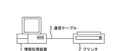
図1は、本実施形態における画像形成システムの構成の一例を示す図である。
図1において、本実施形態の画像形成システムは、情報処理装置1とプリンタ2とが、セントロI/F(インタフェース)に接続された通信ケーブル3を介して相互に接続されて構成される。
なお、本実施形態では、簡単のため情報処理装置1とプリンタ2とが1対1で接続されている場合を示している。しかしながら、以下に示す本実施形態の機能が実行されるのであれば、情報処理装置1及びプリンタ2の少なくとも何れか一方を複数有するシステムであってもよい。また、LANや、WAN等のネットワークを介して、情報処理装置1及びプリンタ2が相互に接続されるシステムであってもよい。(First embodiment)
Next, a first embodiment of the present invention will be described with reference to the drawings.
FIG. 1 is a diagram illustrating an example of a configuration of an image forming system according to the present embodiment.
In FIG. 1, the image forming system of the present embodiment is configured by connecting an
In the present embodiment, the case where the
図2は、情報処理装置1及びプリンタ2の内部構成の一例を示すブロック図である。
まず、情報処理装置1の内部構成の一例について説明する。
CPU201は、制御プログラムを実行する等して情報処理装置1を統括制御する。RAM202は、CPU201の主メモリや、OS(Operating System)及びアプリケーションプログラム等を実行する際のワークエリア等として機能する。
HDドライブ203は、プリンタ制御プログラム等を格納する。ディスプレイ204は、データや処理結果等を表示するためのものであり、例えば、CRTディスプレイや液晶ディスプレイ等である。ROM205は、文書処理を行うためのプログラムを含む各種プログラムや、フォントや、例えばテンプレート用データ等の各種データを記憶する。FIG. 2 is a block diagram illustrating an example of the internal configuration of the
First, an example of the internal configuration of the
The
The
FD(Flexible Disk)206は、プリンタドライバや、処理モード自動制御プログラム等を格納している。FDドライブ207は、FD206に格納されているプログラムやデータを、RAM202やHDドライブ203に出力する。操作部208は、ユーザインタフェースであり、例えばキーボードやポインティングデバイスを備えている。セントロI/F(インタフェース)209は、プリンタ2等の外部装置と通信を行うための通信インタフェースである。 An FD (Flexible Disk) 206 stores a printer driver, a processing mode automatic control program, and the like. The FD drive 207 outputs the program and data stored in the
なお、図2では、CPU201が1つの場合を例に挙げて示した。しかしながら、物理的に複数のCPUを備えたり、1つのCPU内部に複数のコアを持つことで実質的に複数のCPUを備えたりするようにし、OSが、これら複数のCPUにスレッドを振り分けるようにしてもよい。 In FIG. 2, the case where there is one
CPU201は、例えば、RAM202に設定された表示情報RAMへアウトラインフォントを展開する処理(ラスタライズ処理)を実行し、ディスプレイ204でWYSIWYGを可能とするものである。また、CPU201は、ディスプレイ204に表示されたマウスカーソル等で指示されたコマンドに基づいて、予め登録された種々のウィンドウを開き、種々のデータ処理を実行する。ユーザは、プリンタ2で印刷を実行する際に、印刷の設定に関するウィンドウを開き、プリンタ2の設定や、印刷モードの選択を含むプリンタドライバに対する印刷処理方法の設定を行う。 For example, the
次に、プリンタ2の内部構成の一例について説明する。
セントロI/F(インタフェース)210は、情報処理装置1等の外部装置と通信を行うための通信インタフェースである。例えば、セントロI/F210は、プリンタ2が情報処理装置1から通信ケーブル3を経由して印刷データを受信する。ROM211は、モード切換制御プログラム等の各種制御プログラムを記憶する。Next, an example of the internal configuration of the
The Centro I / F (interface) 210 is a communication interface for communicating with an external device such as the
CPU212は、ROM211に記憶された制御プログラムを実行する等して、各デバイスとのアクセスを総括的に制御し、エンジンI/F215を介してプリンタエンジン216に、出力情報としての画像信号を出力する。RAM213は、CPU212の主メモリや、ワークエリアとして機能する。
コプロセッサ214は、簡単な演算を行うものである。プリンタエンジン216は、実際に紙の搬送や、印刷を行うものである。エンジンI/F215は、プリンタエンジン216と、プリンタ2内の各部とのインタフェースである。The
The
本実施形態のプリンタ2は、処理モードとして、フルカラーモードと白黒モードとを備えている。さらに、本実施形態のプリンタ2は、後述するようにホストコンピュータである情報処理装置1から入力された制御情報に基づいて、処理モードを印刷データのページ単位で切り替えることが可能である。
なお、通信ケーブル3は、ネットワークと置き換えることが可能であり、このようにした場合には、セントロI/F209、210は、ネットワークI/F又はネットワークボードと置き換えられる。The
The
CPU212は、ホストコンピュータである情報処理装置1と、セントロI/F210を介して通信することが可能となっており、プリンタ2内の情報等を情報処理装置1に通知することができる。RAM213は、増設ポートに接続されるオプションRAMによりメモリ容量を拡張することができるように構成されている。なお、RAM213は、例えば、出力情報展開領域、環境データ格納領域、及びNVRAM等に用いられる。 The
図3は、プリンタ2に設けられたプリンタエンジン216の構成の一例を示した図である。
エンジンI/F215を介して入力した画像信号に基づいて得られる各色毎の画像データで偏重されたレーザ光が、ポリゴンミラー2101により感光ドラム2102を走査されることにより、静電潜像が形成される。そして、この静電潜像がトナー現像されることにより可視画像が得られ、この可視画像の全色が中間転写体2103へ多重転写されると、カラー可視画像が形成される。さらに、このカラー可視画像が転写材2104へ転写され、転写材2104上にカラー可視画像が定着する。FIG. 3 is a diagram illustrating an example of the configuration of the
An electrostatic latent image is formed by scanning the
以上のような制御を行う画像形成部は、感光ドラム2102を有するドラムユニット、接触帯電ローラを有する一次帯電部、クリーニング部、現像部、中間転写体2103、用紙カセットや各種ローラを含む給紙部、転写ローラを含む転写部、及び定着部を備える。これらの構成部は、公知の技術と同じであるので詳細な説明を省略する。 The image forming unit performing the above control includes a drum unit having a
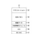
図4は、前記プリンタ制御プログラムを含む印刷関連モジュールが、情報処理装置1のRAM202にロードされ実行可能となった状態のメモリマップの一例を示す図である。 FIG. 4 is a diagram illustrating an example of a memory map in a state in which a print-related module including the printer control program is loaded into the
図4のメモリマップ31には、アプリケーションプログラム32と、空きメモリ33と、関連データ34と、前記プリンタ制御プログラムを含む印刷関連モジュール35と、OS36と、BIOS(Basic Input/Output System)37とが含まれている。 The
なお、後述する図7、8、11、12、14の各ステップによって表される命令を実行する前記処理モード自動制御プログラムは、実行時に、HDドライブ203に記憶されている前記プリンタ制御プログラムを含む印刷関連モジュールの一部として記憶される。そして、CPU201がOS36の管理の下でこの処理モード自動制御プログラムを実行する。 Note that the processing mode automatic control program for executing the commands represented by the steps of FIGS. 7, 8, 11, 12, and 14 to be described later includes the printer control program stored in the
本実施形態の情報処理装置1は、BIOS37、OS36、前記プリンタ制御プログラムを含む印刷関連モジュール35、及びアプリケーション32をCPU201が実行することにより動作する。BIOS37はROM205に書き込まれており、OS36はHDドライブ203に書き込まれている。そして、情報処理装置1の電源がオンされると、BIOSプログラム中のIPL(Initial Program Loading)機能によりHDドライブ203からOS36がRAM202に読み出され、OS36の動作が開始する。 The
そして、前記プリンタ制御プログラムを含む印刷関連モジュール35が実際に動作可能となるのは、ユーザからの指示に基づいて、OS36の管理の下で動作するアプリケーション31より印刷処理が実行された時である。すなわち、印刷関連モジュール35が記憶されているFD206をFDドライブ207にセットされている状態で、OS36及びBIOS37の制御の下に印刷関連モジュール35がFD206又はHDドライブ203から読み出され、RAM202にロードされた時である。又は印刷関連モジュール35がHDドライブ203に保存されている状態で、OS36及びBIOS37の制御の下に印刷関連モジュール35がFD206又はHDドライブ203から読み出され、RAM202にロードされた時である。前述した通り、図4は、前記プリンタ制御プログラムを含む印刷関連モジュール35が情報処理装置1のRAM202にロードされ実行可能となった状態のメモリマップ31を示している。 The printing-related module 35 including the printer control program is actually operable when the printing process is executed by the
なお、前記プリンタ制御プログラムは、情報処理装置1のROM205に格納されていてもよい。また、前記プリンタ制御プログラムのプログラムコードが、FD206からFDドライブ207を介して情報処理装置1にインストールされるようにしてもよい。
さらに、前述したプログラムを記憶しておく記憶媒体は、FD206に限らず、例えば、CD−ROM、CD−R、光磁気ディスク、光ディスク、磁気テープ、不揮発性のメモリカード、又はDVD等であっても構わない。
この場合、記憶媒体から読み出されたプログラムコード自体が本発明の新規な機能を実現することにより、そのプログラムコードを記憶した記憶媒体も本発明を構成することになる。Note that the printer control program may be stored in the
Furthermore, the storage medium for storing the above-described program is not limited to the
In this case, the program code itself read from the storage medium realizes the novel function of the present invention, so that the storage medium storing the program code also constitutes the present invention.
図5は、プリンタ2等と相互に接続されている情報処理装置1における典型的な印刷処理の構成の一例を示した図である。
図5において、アプリケーションプログラム32、グラフィックエンジン1902、プリンタドライバ1903、及びシステムスプーラ1904は、HDドライブ203に保存されたファイルとして存在する。これらは、印刷が実行される際に、OS36等によってRAM202にロードされ実行されるプログラムモジュールである。なお、アプリケーションプログラム32及びプリンタドライバ1903は、FD206やCD−ROM等の他の記憶媒体に保存されていてもよい。また、アプリケーションプログラム32及びプリンタドライバ1903は、ネットワークを経由してHDドライブ203に追加されるようにすることも可能である。FIG. 5 is a diagram showing an example of a typical print processing configuration in the
In FIG. 5, an
アプリケーションプログラム32は、RAM202にロードされて実行される。しかしながら、このアプリケーションプログラム32からプリンタ2に対して印刷の実行を指示する際には、RAM202にロードされて実行可能となっているグラフィックエンジン1902を利用して出力(描画)を行う。 The
グラフィックエンジン1902は、プリンタ2毎に用意されたプリンタドライバ1903に印刷命令を送って、アプリケーションプログラム32で生成された印刷データを、プリンタドライバ1903を用いてプリンタ2の制御コマンドに変換する。このプリンタ制御コマンドは、OS36によってRAM202にロードされたシステムスプーラ1904を経てセントロI/F209を介してプリンタ2へ出力される。 The graphic engine 1902 sends a print command to the printer driver 1903 prepared for each
本実施形態の画像形成システムは、図5に示した構成に加えて、図6に示すように、アプリケーションプログラム32で生成された印刷データを中間コードデータとして一旦スプールするようにしている。 In addition to the configuration shown in FIG. 5, the image forming system of the present embodiment temporarily spools the print data generated by the
図6は、プリンタ2等と相互に接続されている情報処理装置1における印刷処理の構成の一例を特徴的な部分を含めて示した図である。
図6に示すように、本実施形態の情報処理装置1では、グラフィックエンジン1902からプリンタドライバ1903へ印刷命令を送る際に、中間コードからなるスプールファイル2009が一旦生成される。このように、スプールファイル2009を一旦生成すると、スプーラ2003で印刷命令がスプールされているときに、その印刷命令の内容を確認することにより、印刷コマンドを生成する最適な処理モードを選択することが可能となる。例えば、アプリケーションプログラム32のプロセスと、印刷データを作成する印刷プロセッサのプロセスとを分けることも可能になる。FIG. 6 is a diagram showing an example of the configuration of print processing in the
As shown in FIG. 6, in the
図6に示すように、本実施形態では、グラフィックエンジン1902からの印刷命令をプリンタドライバ1903ではなく、スプーラ2003が受け取る。CPU201は、HDドライブ203に格納されているスプーラ2003をRAM202にロードする。このRAM202にロードされたスプーラ2003に印刷命令が送られる。 As shown in FIG. 6, in this embodiment, the
スプーラ2003は、受け取った印刷命令を中間コードに変換してスプールファイル2009に出力する。本実施形態では、スプールファイル2009は、ページ単位で作成される。スプールファイル2009に印刷命令がスプールされる際に、データの種類やサイズ等の情報がカウントアップされる。また、スプールファイル2009は、ページヒント情報を保持している。 The
なお、本実施形態では、スプールファイル2009を、HDドライブ203にファイルとして生成するようにしたが、RAM202に生成するようにしても構わない。また、スプールファイル2009を、バンド単位で作成するようにしてもよい。
スプーラ2003は、HDドライブ203に格納されているスプールファイルマネージャ2004をRAM202にロードし、そのスプールファイルマネージャ2004に対してスプールファイル2009の生成状況を通知する。スプールファイル2009が1ページ分生成されると、スプールファイルマネージャ2004は、スプールファイル2009で保持されたページヒント情報を元に、処理モードを決定する。処理モードを決定する方法の具体例は、図11のフローチャートのステップS7003で詳述する。In the present embodiment, the
The
スプールファイルマネージャ2004は、決定した処理モードに応じたPDLプロセッサ2005、2006を、HDドライブ203から読み出してRAM202にロードする。そして、スプールファイルマネージャ2004は、PDLプロセッサ2005、2006に対して、スプールファイル2009に記述された中間コードの印刷処理を行うように指示する。前述した例では、処理の軽いページ(抽象度の高いページ)に分類されたスプールファイル2009に記述された中間コードの印刷処理を、PDLプロセッサ2005に対して指示する。一方、処理の重いページ(抽象度の低いページ)に分類されたスプールファイル2009に記述された中間コードの印刷処理を、PDLプロセッサ2006に対して指示する。 The
PDLプロセッサ2005、2006は、互いに別のプロセス又は別のスレッドで動作している。本実施形態では、PDLプロセッサ2005を、抽象度の高いPDL(Page Description Language)系の印刷データファイル2010(抽象度の高いPDLコマンド)を生成するモジュールとしている。また、PDLプロセッサ2006を、抽象度の低い中間データ系(イメージモードも含む)の印刷データファイル2010(プリミティブ(primitive)な描画命令に変換されたPDLコマンド)を生成するモジュールとしている。 The
PDLプロセッサ2005、2006は、スプールファイルマネージャ2004から指示されたスプールファイル2009を処理して1ページ分の印刷データファイル2010を生成する。図6に示した例では、スプールファイル2009aは抽象度の高いものであるので、PDLプロセッサ2005は、このスプールファイル2009aを処理して1ページ分の印刷データファイル2010aを生成する。一方、スプールファイル2009bは抽象度の低いものであるので、PDLプロセッサ2006は、このスプールファイル2009bを処理して1ページ分の印刷データファイル2010bを生成する。 The
なお、本実施形態では、印刷データファイル2010が、HDドライブ203にファイルとして生成されるようにしている。しかしながら、印刷データファイル2010が、RAM202に生成されるようにしても構わない。 In the present embodiment, the print data file 2010 is generated as a file in the
PDLプロセッサ2005、2006は、1ページ分の印刷データファイル2010を生成すると、その印刷データファイル2010を別のプロセスで動作する出力マネージャ2007に即座に出力する。
出力マネージャ2007は、受け取った印刷データファイル2010を、システムスプーラ1904を経由してプリンタ2に出力する。When the
The
図7は、前記プリンタ制御プログラムの概略処理の一例を説明するフローチャートである。
まず、ステップS401において、CPU201は、印刷の実行時にアプリケーションプログラム32から受け取った印刷データ(例えばコードデータ)を中間コードに変換し、HDドライブ203に一時的に保存する。この中間コードの生成と保存と共に、CPU201は、アプリケーションプログラム32から印刷要求がなされた個々の印刷データの情報をRAM202に記憶し、ページ単位でその情報を保存する。FIG. 7 is a flowchart for explaining an example of schematic processing of the printer control program.
First, in step S <b> 401, the
次に、ステップS402において、CPU201は、ステップS401で一時的に保存された中間コードと、ステップS401でRAM202に記憶されたページ単位の情報とに基づいて、印刷データを生成するための処理モードを決定する。そして、CPU201は、決定した処理モードでプリンタ2に出力する印刷データファイル2010を生成する。 Next, in step S402, the
なお、前述したようにして中間コードを生成しなくても、本実施形態の画像形成システムを実行することが可能である。例えば、CPU201は、印刷データであるコードデータを生成する際に、そのコードデータを一度解析することにより、印刷データのページあたりのデータ種別の統計を取る。そして、1ページ分の印刷データファイルを生成した後に、コードデータから再度コードデータを生成し直すことも考えられる。 Note that the image forming system of this embodiment can be executed without generating the intermediate code as described above. For example, when generating code data that is print data, the
図8は、図7に示したステップS401の詳細な処理を説明するフローチャートである。なお、この図5に示す処理は、スプーラ2003がスプールファイル2009を生成するときにCPU201が行う。 FIG. 8 is a flowchart for explaining detailed processing of step S401 shown in FIG. The processing shown in FIG. 5 is performed by the
ステップS5001では、以下のジョブ初期化処理を行う。
このジョブ初期化処理では、まず、中間コードを一時的に保存するためのスプールファイル2009と、ジョブを識別するためのジョブ識別子とを情報処理装置1のHDドライブ203に作成し、作成したスプールファイル2009をオープンする。そして、中間コードの情報をページ毎に保存するためにジョブ識別子を初期化し、ジョブ識別子をスプールファイルマネージャ2004へ通知する。In step S5001, the following job initialization process is performed.
In this job initialization process, first, a
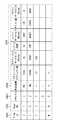
図9は、ジョブ識別子の一例を示した図である。
図9において、ジョブ識別子は、ファイルID(FileID)1001と、ページナンバ(PageNo)1002と、ステイタス1003と、判定結果1004と、中間コマンド情報105とをページ毎に有している。FIG. 9 is a diagram illustrating an example of a job identifier.
In FIG. 9, the job identifier has a file ID (FileID) 1001, a page number (PageNo) 1002, a
ファイルID(FileID)1001は、中間コードが格納されているスプールファイル2009を特定するための情報である。ページナンバ(PageNo)1002は、OS36から受け取ったページ順を示す情報である。ステイタス1003は、プリンタ2のステイタス(status)の管理を行うための情報である。判定結果1004は、決定した処理モードを示す情報である。中間コマンド情報1005は、格納した中間コマンドに関する情報である。 A file ID (FileID) 1001 is information for specifying the
前記ジョブ初期化処理は、前記ジョブ識別子を全てクリアする。具体的に説明すると、例えば、メンバーのファイルID(FileID)1001に格納するページカウンタNを「1」にする。また、ステイタス1003を、スプール中を示す「1」に変更する。これにより、1ページ目が実行されていることを表すようにする。 The job initialization process clears all the job identifiers. More specifically, for example, the page counter N stored in the member's file ID (FileID) 1001 is set to “1”. Also, the
次に、ステップS5002において、アプリケーションプログラム32からの印刷要求を受け付ける。
次に、ステップ5003において、ステップS5002で受け付けた印刷要求が、ジョブの終了か否かを判定する。この判定の結果、受け付けた印刷要求が、ジョブの終了である場合には、後述するステップS5011に進む。一方、受け付けた印刷要求が、ジョブの終了でない場合には、ステップS5004に進み、ステップS5002で受け付けた印刷要求が、改ページであるか否かを判定する。この判定の結果、受け付けた印刷要求が、改ページでなく、受け付けた印刷要求が印刷データの場合には、ステップS5005〜S5007を省略してステップS5008に進む。一方、受け付けた印刷要求が、改ページである場合には、ステップS5005に進む。In step S5002, a print request from the
Next, in
ステップS5008では、受け付けた印刷要求(印刷データ)を中間コマンドに変換する。次に、ステップ5009において、ステップS5008で生成した中間コマンドに関する中間コマンド情報1005を、ジョブ識別子に反映させる。
次に、ステップS5010において、中間コマンドをHDドライブ203にあるスプールファイル2009へ書き込む。
そして、ステップS5002に戻り、アプリケーションプログラム32からの印刷要求を再度受け付ける。このステップS5002〜S5010までの処理を、ジョブを終了する印刷要求をアプリケーションプログラム32から受け取るまで繰り返し行う。In step S5008, the received print request (print data) is converted into an intermediate command. In step 5009, the
In step S5010, the intermediate command is written into the
Then, the process returns to step S5002, and the print request from the
ステップS5004において、ステップS5002で受け付けた印刷要求が、改ページであると判断した場合には、ステップS5005に進み、オープンしているスプールファイル2009をクローズする。そして、ジョブ識別子のステイタス1003の値を、データのスプールの終了を示す「2」に変更する。その後、スプールファイルマネージャ2004に、処理が終了したページ情報を通知することにより、そのページの処理をスプールファイルマネージャ2004に移す。スプールファイルマネージャ2004に通知するページ情報は、例えば、生成した中間コマンドを一時的に格納しているスプールファイル2009のファイル名と、ジョブ識別子に記録した中間コマンド情報1005である。
次に、ステップS5006において、次のページに対応する中間コマンドを一時的に格納するためのスプールファイル2009を開く。
次に、ステップS5007において、ジョブ識別子で使うページカウンタNをインクリメントして、ステップS5008に進む。If it is determined in step S5004 that the print request received in step S5002 is a page break, the process advances to step S5005 to close the
In step S5006, a
In step S5007, the page counter N used for the job identifier is incremented, and the process advances to step S5008.
ステップS5003において、ステップS5002で受け付けた印刷要求が、ジョブの終了であると判断した場合には、アプリケーションプログラム32からの印刷要求は全て終了であるので、ステップS5011に進む。そして、スプールファイルマネージャ2004へ印刷処理の進捗状況を通知し、図7のステップS401の処理を終了する。 If it is determined in step S5003 that the print request accepted in step S5002 is the end of the job, all print requests from the
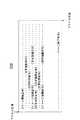
図10は、図7のステップS401の処理によってHDドライブ203に生成されるスプールファイル2009の内容の一例を示した図である。なお、図10において、[ページ開始命令]、[文字登録命令]、及び[文字印字命令]等が記述されているが、これらはファイル中の印字データを便宜的に分かり易くするための標記であり、実際は、これらの記述がバイナリ形式であっても構わない。 FIG. 10 is a diagram showing an example of the contents of the
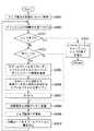
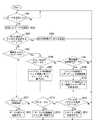
次に、図11のフローチャートを参照しながら、スプール済みのスプールファイル2009のファイル名と、ジョブ識別子に記録された中間コマンド情報1005とを受け取ったスプールファイルマネージャ(プロセス又はスレッド)2004の処理の一例を説明する。
まず、ステップS7001において、スプールが終了したページ番号の通知を受け取ると、ステップS7002において、そのページ番号に対応するページの中間コマンド情報1005を読み出す。Next, an example of processing of the spool file manager (process or thread) 2004 that has received the spooled
First, in step S7001, when a notification of the page number for which spooling has been completed is received, in step S7002, the
次に、ステップS7003において、ステップS7002で読み出した中間コマンド1005の値から、そのページを処理するのに最も適した処理モードを決定し、決定した処理モードを、ジョブ識別子の判定結果1004に記録する。
本実施形態では、切り替え対象となる処理モードは、例えば、抽象度の高いPDLコマンドを送るPDLモードと、抽象度の低いコマンドを送るイメージモードである。このように処理モードを切り替えるのは、全体の処理速度を向上させるためである。
そこで、例えば、ジョブ識別子に記録されている中間コマンドの描画要素の個数(グラフィックオブジェクト数)と、グラフィックスデータサイズとから、PDLモードで処理したときの処理時間と、イメージモードで処理したときの処理時間の両方を予測する。そして、予測した処理時間が短い方を選択ことで処理モードを決定する。In step S7003, the most suitable processing mode for processing the page is determined from the value of the
In the present embodiment, the processing modes to be switched are, for example, a PDL mode for sending a PDL command with a high level of abstraction and an image mode for sending a command with a low level of abstraction. The reason for switching the processing mode in this way is to improve the overall processing speed.
Therefore, for example, from the number of drawing elements (number of graphic objects) of the intermediate command recorded in the job identifier and the graphics data size, the processing time when processing in the PDL mode, and when processing in the image mode Predict both processing times. Then, the processing mode is determined by selecting the shorter processing time predicted.
描画命令が少ないページでプリンタ2の処理能力を超えないページであれば、印刷データを抽象度の高いままPDLコマンドを生成するPDLモードの方が、転送する印刷データのサイズを小さくでき、印刷データの生成時間も最短にすることができる。
一方、巨大なイメージデータや、複雑なグラフィックス描画命令を含むページの印刷データをそのままPDL化してプリンタ2に送ると、印刷データのサイズがプリンタ2の処理能力を超えてしまう。近年の情報処理装置1では、プリンタ2よりも高速なCPUを使っているものが一般的である。したがって、情報処理装置1で抽象度を下げたコマンド(最も極端なものはページ全体のイメージデータ)にまで展開してしまう方が全体の処理時間を短くすることができる。If the page has few drawing commands and does not exceed the processing capability of the
On the other hand, if print data of a page including huge image data or a complicated graphics drawing command is converted into PDL as it is and sent to the
ステップS7004において、ステップS7003で決定した処理モードに適したPDLプロセッサ2005、2006がすでに起動されているか否かを判定する。この判定の結果、決定した処理モードに適したPDLプロセッサ2005、2006が起動していない場合は、ステップS7006に進み、決定した処理モードに適したPDLプロセッサ2005、2006を起動する。一方、決定した処理モードに適したPDLプロセッサ2005、2006が起動している場合は、ステップS7006を省略してステップS7005に進む。
そして、ステップ7005において、起動しているPDLプロセッサ2005、2006にスプールファイル2009を処理するように通知する。In step S7004, it is determined whether
In
次に、図12のフローチャートを参照しながら、スプールファイル2009に一時的に記憶されている中間コマンドから、印刷データファイル2010を生成する際のPDLプロセッサ2005、2006(CPU201)の処理の一例を説明する。 Next, an example of processing of the
まず、ステップS8001において、HDドライブ203に記憶されているジョブ識別子をスキャンし、自分が処理すべきページを検索する。例えば、起動しているPDLプロセッサが、PDLモード用のPDLプロセッサ2005であれば、ステイタス1003が「2」であって、且つ判定結果1004がPDLにセットされているファイルID1001を検索する。そして、検索したファイルID1001に対応するスプールファイル2009をオープンする。 First, in step S8001, the job identifier stored in the
次に、ステップS8002で、これから生成する印刷データを一旦保存する印刷データファイル2010をオープンする。印刷データの保存先は、HDドライブ203でも、RAM202の関連データ31が記憶される領域でもよい。そして、ジョブ中のポジション(ページ位置)が判読可能な領域情報を、オープンした印刷データファイル2010に付加する。 In step S8002, a print data file 2010 for temporarily storing print data to be generated is opened. The print data storage destination may be the
次に、実際に中間コマンドの検索を開始する。まず、ステップS8003では、中間コマンドの読み出しを図10に示した印刷命令単位で行う。図10に示したスプールファイル2009に一時的に保存されている中間コマンドから最初に読み出される中間コマンドは[ページ開始命令〕となる。続けて、中間コマンドがスプールファイル2009の終端(末尾)まで読み出される。 Next, the search for the intermediate command is actually started. First, in step S8003, the intermediate command is read in units of print commands shown in FIG. The first intermediate command read from the intermediate command temporarily stored in the
この中間コマンドを読み出す過程において、ステップS8004では、CPU201は、現在の読み出し位置がスプールファイル2009の終端か否かを判定する。この判定の結果、現在の読み出し位置がスプールファイル2009の終端でない場合は、ステップS8005に進みCPU201は、指定された処理モードに従って中間コマンドから印刷データを生成する。そして、ステップS8002で開いた印刷データファイル2010に保存する。 In the process of reading this intermediate command, in step S8004, the
ステップS8004で、現在の読み出し位置がスプールファイル2009の終端か否かを判定し、1ページ分の中間コマンドから印刷データを生成し終えると、ステップS8006に進む。ステップS8006では、ページ終了命令を生成して、ステップS8005で印刷データを保存したファイルに追記する。そして、ジョブ識別子のステイタス1003には処理終了を示す「3」をセットし、印刷データを生成したページ番号と、保存した印刷データとを出力マネージャ2007に通知する。
そして、ステップS8007において、印刷データの生成が終了した中間コマンドが一時的に保存されているスプールファイル2009をクローズして、削除する。In step S8004, it is determined whether or not the current reading position is the end of the
In step S8007, the
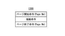
図13に、PDLプロセッサ2005、2006がステップS8002〜S8005で生成する印刷データの具体例を示す。図13に示す印刷データ1300では、ページ開始命令の属性と、ページ終了命令の属性として、アプリケーションプログラム32から受け取った本来のページ番号をつけることで、ジョブ中のページ位置を示している。 FIG. 13 shows a specific example of print data generated by the
次に、図14のフローチャートを参照しながら、プリンタドライバとしては最後の処理である出力マネージャ2007(CPU201)の処理の一例を説明する。
まず、ステップS9001において、PDLプロセッサ2005、2006が印刷データを1ページ分生成し終わった通知を受けると、HDドライブ203にあるジョブ識別子をスキャンし、プリンタ2に出力可能なページを検索する。図9に示した例では、ステイタス1003が「3」であれば、中間コマンドから印刷データへの変換は終わっているので、ステイタス1003が「3」のページの中から最もページナンバ1002が小さいページを選択する。そして、そのページの印刷データファイル2010を取得する。
次に、ステップS9002において、ステップS9001で取得した印刷データファイル2010に含まれる印刷データを、システムスプーラ1904を介してプリンタ2に出力する。そして、全ての処理が終了したことを示す「4」をジョブ識別子のステイタス1003に記録する。
次に、ステップ9003において、プリンタ2に出力された印刷データを記録していた印刷データファイル2010を削除する。Next, an example of processing of the output manager 2007 (CPU 201), which is the last processing for the printer driver, will be described with reference to the flowchart of FIG.
First, in step S9001, when the
In step S9002, the print data included in the print data file 2010 acquired in step S9001 is output to the
In step 9003, the print data file 2010 in which the print data output to the
以上のように、出力マネージャ2007は、PDLプロセッサ2005、2006が生成した印刷データをページ単位で受け取り次第、プリンタ2に出力する。複数のPDLプロセッサ2005、2006が別々のスレッドで並列に印刷データを生成した場合、処理時間を要するページが、処理の軽いページに追い越されてプリンタ2に出力されることが考えられる。 As described above, the
その場合、プリンタ2が受け取る印刷データは、図15に示すように、ページ順が入れ替わったものになる。しかしながら、描画命令が、ページ開始命令と、ページ終了命令とで囲まれているので、プリンタ2で出力するページ順を整形しなおすことは可能である。
なお、バンド毎に描画命令を送るようなPDLコマンド形式の場合には、「ページ番号」と「バンド番号」とを描画命令につけることによって、バンド単位で送る順番を変えることも可能である。In that case, the print data received by the
In the case of a PDL command format in which a drawing command is sent for each band, it is possible to change the sending order in units of bands by attaching “page number” and “band number” to the drawing command.
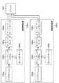
図16は、図15に示したように、ページ順が入れ替わった印刷データを処理可能なプリンタ2の内部構成の一例を示したブロック図である。
図16において、受信バッファ1501に格納されたPDLコマンドは、CPU212で動作するプログラムであるトランスレータ1502で中間データ1506に変換された後、RAM213においてページ単位で管理される。具体的に中間データ1506の各ページは、RAM213に形成されたページ管理テーブル1505に記録される。このページ管理テーブル1505は、レンダラー1503に渡される。FIG. 16 is a block diagram illustrating an example of an internal configuration of the
In FIG. 16, the PDL command stored in the
レンダラー1503は、CPU212で動作するプログラムが、ハードウェア等を使って中間データからイメージデータを生成するためのモジュールである。レンダラー1503は、トランスレータ1502から渡されるページ管理テーブル1505を参照して出力可能なページがあるか否かを判定し、出力可能なページがあれば中間データ1506を読み出してイメージデータに展開する処理を実行する。RAM213に展開されたイメージデータは、ビデオ信号に変換された後、プリンタエンジン216に送られ、印字処理が完了する。印字処理が完了したページは、前記ページ管理テーブルに記録される。 A
次に、図17のフローチャートを参照しながら、トランスレータ1502における処理の一例を説明する。
まず、ステップS1601において、初期化処理としてページ管理テーブル1505を作成する。
次に、ステップS1602において、受信バッファ1501に格納されたPDLコマンドを読み出す。次に、ステップS1603において、ジョブが終了したか否かを判定する。この判定の結果、ジョブが終了した場合には処理を終了する。一方、ジョブが終了していない場合には、ステップS1604に進み、ジョブが改ページか否かを判定する。Next, an example of processing in the
First, in step S1601, a page management table 1505 is created as initialization processing.
In step S1602, the PDL command stored in the
この判定の結果、ジョブが改ページの場合には、ステップS1605に進み、次のページのPDLデータを処理することができるように、ページ管理テーブル1505を更新する。具体的に、ステップS1602〜S1605を繰り返して、1ページ分の中間データ1506を生成すると、ページ管理テーブル1505の対応するページ部に受信済みであることを示すフラグをON(オン)する。
一方、ジョブが改ページでない場合には、ステップS1605を省略してステップS1606に進む。
そして、ステップS1606において、PDLコマンドから中間データを生成し、RAM213に保存する。If it is determined that the job is a page break, the process advances to step S1605 to update the page management table 1505 so that the PDL data of the next page can be processed. Specifically, when steps S1602 to S1605 are repeated to generate
On the other hand, if the job is not a page break, step S1605 is omitted and the process proceeds to step S1606.
In step S1606, intermediate data is generated from the PDL command and stored in the
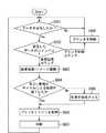
次に、図18のフローチャートを参照しながら、レンダラー1503における処理の一例を説明する。なお、ここでは、レンダラー1503は、トランスレータ1502とは独立した別々のプロセスで動作するものとし、トランスレータ1502が中間データ1506を1ページ分だけRAM213に保存すると起動するものとする。
まず、ステップS1701において、ページ管理テーブル1505を確認する。次に、ステップS1702において、ページ管理テーブル1505を確認した結果に基づいて、処理(出力)すべきページがあるか否かを判定する。この判定の結果、処理すべきページがない場合には、処理を終了する。一方、処理すべきページがある場合には、ステップS1703に進み、ページ管理テーブル1505を確認した結果に基づいて、出力可能なページがあるか否かを判定する。Next, an example of processing in the
First, in step S1701, the page management table 1505 is confirmed. In step S1702, it is determined whether there is a page to be processed (output) based on the result of checking the page management table 1505. As a result of the determination, if there is no page to be processed, the process is terminated. On the other hand, if there is a page to be processed, the process advances to step S1703 to determine whether there is a page that can be output based on the result of checking the page management table 1505.
この判定の結果、出力可能なページがある場合には、ステップS1704に進み、出力可能なページの中間データをイメージデータ(例えばビットマップ)に展開する処理を行う。そして、イメージデータをビデオ信号に変換し、そのビデオ信号をプリンタエンジン216に送信する。プリンタエンジン216は、前記ビデオ信号に基づいて、印字と、排紙とを行う。
次に、ステップS1705において、ページ管理テーブル1505に、対応するページが出力(印刷)済みであることを記録する。具体的にページ管理テーブル1505の対応するページ部に印刷済みであることを示すフラグをON(オン)する。
ステップS1703において出力可能なページがないと判定した場合は、ステップS1704、S1705を省略してステップS1701に戻る。そして、トランスレータ1502が出力可能なページの中間データを生成して、ページ管理テーブル1505を更新するまで待機する。以上のように、処理(出力)すべきページがなくなるまでステップS1701〜S1705を繰り返し実行する。If it is determined that there is a page that can be output, the process advances to step S1704 to perform processing for expanding intermediate data of the page that can be output into image data (for example, bitmap). Then, the image data is converted into a video signal, and the video signal is transmitted to the
In step S1705, it is recorded in the page management table 1505 that the corresponding page has been output (printed). Specifically, a flag indicating that printing has been performed on the corresponding page portion of the page management table 1505 is turned ON.
If it is determined in step S1703 that there is no page that can be output, steps S1704 and S1705 are omitted, and the process returns to step S1701. Then, the intermediate data of pages that can be output by the
図19は、ページ管理テーブルの構成の一例を模式的に示した図である。
図19において、ページ管理テーブル1505a、1505bは、印刷順、受信済フラグ、及び印刷済フラグを1セットとして構成されるテーブルである。そして、このセットが出力するページ分だけ作成される。
印刷順は、PDLプロセッサ2005、2006で生成された印刷データ1300内のページ開始命令に格納されているページ番号をどの順番に出力するのかを示すためのものである。通常の印刷では、この印刷順の欄には、「1,2,3,・・・」の値が入り、アプリケーションプログラム32から渡された順番に印刷を行うが、製本印刷、両面印刷、又は逆順印刷を行う場合には、初期化時にこの印刷順の値が変化する。FIG. 19 is a diagram schematically illustrating an example of the configuration of the page management table.
In FIG. 19, page management tables 1505a and 1505b are tables configured as a set of a printing order, a received flag, and a printed flag. Only the pages that are output by this set are created.
The print order is for indicating in which order the page numbers stored in the page start command in the
受信済フラグは、トランスレータ1502が1ページ分の中間データ1506を作成し終わったときにステップS1605でオンされるフラグである。
印刷済フラグは、レンダラー1503が出力し終わったときにステップS1705でオンされるフラグである。The received flag is a flag that is turned on in step S1605 when the
The printed flag is a flag that is turned on in step S1705 when the
図19(a)に示すページ管理テーブル1505aでは、1ページと、3ページは受信済みであり、1ページだけが出力(印刷)済みであることを示している。
この状態は、3ページ目については、中間データは生成されているが、次に出力(印刷)すべきページである2ページ目の受信が終わっていないため、出力(印刷)することができないことを示している。In the page management table 1505a shown in FIG. 19A, one page and three pages have been received, and only one page has been output (printed).
In this state, for the third page, intermediate data has been generated, but the second page, which is the next page to be output (printed), has not been received, so output (printing) cannot be performed. Is shown.
図19(b)に示すページ管理テーブル1505bは、図19(a)に示すページ管理テーブル1505aよりも処理が進んだ状態を示している。すなわち、ページ管理テーブル1505bは、1ページ目と3ページ目に加えて2ページ目と4ページ目の中間データも生成され、2ページ目の印刷も終了し、3ページ目の印刷処理が実行中であることを示している。 A page management table 1505b shown in FIG. 19B shows a state where the processing has progressed more than the page management table 1505a shown in FIG. That is, the page management table 1505b generates intermediate data for the second and fourth pages in addition to the first and third pages, the second page is also printed, and the third page is being printed. It is shown that.
次に、図20及び図21を参照しながら、本実施形態の効果を説明する。図20は、従来のシングルスレッドで処理した場合の処理時間と、本実施形態のマルチスレッド(奇数ページ対するスレッドと偶数ページ対するスレッドとの2つのスレッド)で処理した場合の処理時間とを説明する図である。
図20(a)は、従来のシングルスレッドで印刷命令を生成し、印刷ジョブの入力順に印刷命令を送信するプリンタドライバが、印刷命令(印刷データ)を生成する時間、印刷命令を送信する時間、及びプリンタが排紙を行う時間を模式的に示したものである。Next, the effect of this embodiment will be described with reference to FIGS. FIG. 20 illustrates the processing time when processing is performed with a conventional single thread and the processing time when processing is performed with the multi-thread of this embodiment (two threads, a thread for odd pages and a thread for even pages). FIG.
FIG. 20A illustrates a time for generating a print command (print data), a time for transmitting a print command by a printer driver that generates a print command with a conventional single thread and transmits the print commands in the order of input of the print job, 4 schematically shows the time when the printer discharges paper.
図20(a)において、5ページの連続した印刷ジョブのうち、2ページ目と5ページ目が印刷データの生成に時間がかかる印刷ジョブとなっている。このため、これら2ページ目と5ページ目における印刷命令の送信時間が長くなり、その間プリンタは待ち状態が続くことになる。 In FIG. 20A, among the continuous print jobs of five pages, the second and fifth pages are print jobs that take time to generate print data. For this reason, the transmission time of the print command on the second and fifth pages becomes longer, and the printer continues to wait during that time.
図20(b)は、図20(a)に示したのと同じ印刷ジョブを、本実施形態の手法で処理した場合の処理時間を模式的に示したものである。
図20(b)に示す例では、PDLプロセッサ2005、2006の種類は同じとする。そして、スプールファイルマネージャ2004は、ページの処理の重さで処理モードを切り替えるのではなく、機械的に順番に印刷処理をPDLプロセッサ2005、2006に振り分けた場合を示している。図20(b)の例は、PDLプロセッサが2つある場合である。PDLプロセッサが3つある場合は、1の倍数のページの印刷命令をPDLプロセッサ1で生成し、2の倍数のページの印刷命令をPDLプロセッサ2で生成し、3の倍数のページの印刷命令をPDLプロセッサ3で生成する。FIG. 20B schematically shows the processing time when the same print job as shown in FIG. 20A is processed by the method of this embodiment.
In the example shown in FIG. 20B, the types of the
図20(b)において、偶数ページである2ページ目の印刷命令の生成に時間がかかっている間に、奇数ページである1ページ目と3ページ目の印刷命令の生成が終了したために、2ページ目の印刷命令の前に3ページ目の印刷命令がプリンタ2に送信される。
印刷命令は生成し終わるまでプリンタ2に送信できないが、このようにすれば、情報処理装置1とプリンタ2との間の転送経路が効率的に使われ、且つプリンタ2が待ち状態になる時間を減らすことができる。In FIG. 20B, while the generation of the print command for the second page, which is an even page, takes time, the generation of the print commands for the first page and the third page, which are odd pages, is completed. The print command for the third page is transmitted to the
The print command cannot be transmitted to the
図21は、従来のシングルスレッドで処理した場合の処理時間と、本実施形態のマルチスレッド(軽いページに対するスレッドと重いページに対するスレッドとの2つのスレッド)で処理した場合の処理時間とを説明する図である。
図21(a)に示すように、従来は、印刷命令の生成を1つのスレッドで行っている。このため、処理に時間がかかる重いページが印刷ジョブの途中に存在し、その重いページをプリンタドライバでイメージデータに展開すると、その間は、プリンタに印刷命令(印刷データ)が送信されない。したがって、全体の処理効率が下がってしまう。
それに対して、図21(b)に示すように、軽いページ用のPDL生成スレッドと、重いページ用のイメージモード専用スレッドとで、処理を分担して印刷命令を生成すると、重いページを処理している間に、軽いページの印刷命令を生成してプリンタ2に送信することができる。これにより、情報処理装置1とプリンタ2との両方のリソースを効率的に使うことができ、トータルの印刷時間を短縮することができる。FIG. 21 illustrates the processing time when processing is performed with a conventional single thread and the processing time when processing is performed with the multi-thread of this embodiment (two threads: a thread for a light page and a thread for a heavy page). FIG.
As shown in FIG. 21A, conventionally, a print command is generated by one thread. For this reason, a heavy page that takes time to process exists in the middle of a print job, and when the heavy page is developed into image data by the printer driver, a print command (print data) is not transmitted to the printer during that time. Accordingly, the overall processing efficiency is lowered.
On the other hand, as shown in FIG. 21B, when a print command is generated by sharing a process between a PDL generation thread for light pages and an image mode dedicated thread for heavy pages, a heavy page is processed. In the meantime, a light page print command can be generated and transmitted to the
以上のように、本実施形態では、印刷データの処理モード毎に複数の処理スレッドを立ち上げ、これら複数の処理スレッドを並行してPDLプロセッサ2005、2006で処理して印刷データファイル2010を生成する。そして、印刷データファイル2010ができ次第、その印刷データファイル2010に含まれている印刷データをプリンタ2に出力することにより、情報処理装置1とプリンタ2との間の通信経路を効率的に使用することができると共に、プリンタ2で処理が行われない時間を減らすことができ、印刷に要する全体の処理時間を短縮することが可能になる。 As described above, in this embodiment, a plurality of processing threads are started for each print data processing mode, and the plurality of processing threads are processed in parallel by the
なお、本実施形態では、ページ管理テーブル1505を確認した結果に基づいて、出力可能なページがあるか否かを判定することによって、情報処理装置1から生成順に送信された印刷データを並べ替えてページ順に印刷を行うようにしている。しかしながら、情報処理装置1が、生成した印刷データを印刷順に並べ替えてプリンタ2に送信し、プリンタ2が受信順に印刷データの印刷処理を行うようにしてもよい。 In this embodiment, print data transmitted from the
(第2の実施形態)
次に、本発明の第2の実施形態について説明する。前述した第1の実施形態では、Windows(登録商標)2k/XPのように、OSが印刷命令毎に印刷命令を渡すようにしたが、本実施形態では、アプリケーションプログラム又はOSが印刷命令をファイルのようにまとまった形式で渡すようにしている。このように本実施形態と前述した第1の実施形態とは、印刷命令の処理の一部が異なるだけである。したがって、本実施形態の説明において、前述した第1の実施形態と同一の部分については、図1〜図21に付した符号と同一の符号を付す等して詳細な説明を省略する。(Second Embodiment)
Next, a second embodiment of the present invention will be described. In the first embodiment described above, the OS passes a print command for each print command as in Windows (registered trademark) 2k / XP. However, in this embodiment, the application program or the OS stores the print command as a file. I am trying to pass it in a unified format. Thus, the present embodiment and the first embodiment described above differ only in part of the print command processing. Therefore, in the description of the present embodiment, the same parts as those in the first embodiment described above are denoted by the same reference numerals as those in FIGS.
図22は、本実施形態の情報処理装置2200における印刷処理の構成の一例を示した図である。
図22において、プロセッサマネージャ2203は、アプリケーションプログラム2201又はOS2202が作成した印刷要求ファイル2209を受け取ることで、処理を開始する。なお、本実施形態のアプリケーションプログラム2201及びOS2202と、第1の実施形態のアプリケーションプログラム32及びOS36とは、このような印刷要求ファイル2209によって、印刷命令をファイルの形式で渡すこと以外は同じである。FIG. 22 is a diagram illustrating an example of a configuration of print processing in the
In FIG. 22, the processor manager 2203 receives the print request file 2209 created by the application program 2201 or the
プロセッサマネージャ2203は、受け取った印刷要求ファイル2209を解析して処理モードを決定する。
プロセッサマネージャ2203は、決定した処理モードに応じたPDLプロセッサ2005、2006を、HDドライブ203から読み出してRAM202にロードする。そして、プロセッサマネージャ2203は、PDLプロセッサ2005、2006に対して、印刷要求ファイル2209に記述された中間コードの印刷処理を行うように指示する。The processor manager 2203 analyzes the received print request file 2209 and determines the processing mode.
The processor manager 2203 reads the
PDLプロセッサ2005、2006は、互いに別のプロセス又は別のスレッドで動作している。本実施形態においても、PDLプロセッサ2005は、抽象度の高いPDL系の印刷データファイル2010を生成するモジュールであり、PDLプロセッサ2006は、抽象度の低い中間データ系の印刷データファイル2010を生成するモジュールであるとする。 The
PDLプロセッサ2005、2006は、プロセッサマネージャ2203から指示された印刷要求ファイル2209を処理して1ページ分の印刷データファイル2210を生成する。
そして、PDLプロセッサ2005、2006は、1ページ分の印刷データファイル2010を生成する(スプールする)と、その印刷データファイル2010を別のプロセスで動作する出力マネージャ2007に通知する。
出力マネージャ2007は、受け取った印刷データファイル2010を、システムスプーラ1904を経由してプリンタ2に出力する。The
When the
The
このように、本実施形態では、動作するOSの環境によって、OSが渡す印刷命令の方式が第1の実施形態とは異なる。しかしながら、印刷命令を領域毎に分割し、複数のスレッドで印刷データ(印刷データファイル2010)を生成する構成をとるようにしていれば、本実施形態においても、第1の実施形態と同様の効果を得ることができる。 As described above, in the present embodiment, the print command method passed by the OS differs from that in the first embodiment depending on the operating OS environment. However, if the configuration is such that the print command is divided into regions and the print data (print data file 2010) is generated by a plurality of threads, the present embodiment also has the same effect as the first embodiment. Can be obtained.
なお、前述した各実施形態においては、前述した処理を実行する制御プログラムを含む印刷関連モジュールを記憶する媒体をFD206又はHDドライブ203としたが、それ以外にCD−ROMやICメモリカード等としてもよい。さらに、制御プログラム単体、又は制御プログラムを含む印刷関連モジュールをROM205に記憶しておき、これをメモリマップの一部となすように構成し、制御プログラムをCPU201で直接実行することも可能である。 In each of the above-described embodiments, the medium for storing the print-related module including the control program for executing the above-described processing is the
(第3の実施形態)
次に、本発明の第3の実施形態について説明する。
図23は、本実施形態における情報処理装置の構成の一例を示すブロック図である。
図23において、情報処理装置2301はコンピュータである。情報処理装置2301は、CPU、メモリ、ハードディスク、フレキシブルディスクドライブ、キーボード、マウス、ディスプレイ、及びネットワークインタフェース等、一般的な情報処理装置におけるハードウェアを備える。すなわち、情報処理装置2301のハードウェアの構成は、例えば、図1に示したようになる。(Third embodiment)
Next, a third embodiment of the present invention will be described.
FIG. 23 is a block diagram illustrating an example of the configuration of the information processing apparatus according to the present embodiment.
In FIG. 23, the
次に、情報処理装置2301のソフトウェアの構成の一例について説明する。
オペレーティングシステム(OS)2302は、クライアント2301が備えるハードウェアと、アプリケーション2303、プリンタドライバ2304、ランゲージモニタ2305、及びネットワークポートドライバ2306等のソフトウェアとを管理する。代表的なオペレーティングシステムとしては、例えばマイクロソフト社のWindows(登録商標)などが挙げられる。Next, an example of the software configuration of the
An operating system (OS) 2302 manages hardware included in the
アプリケーションプログラム2303は、例えばワードプロセッサのように、文書や図形を作成したり編集したりする機能と、写真画像を編集する機能とを備える。また、アプリケーションプログラム2303は、作成及び編集したアプリケーションデータに基づく印刷指示を行うこともできる。
プリンタドライバ2304は、アプリケーションプログラム2303が発行した印刷指令を、オペレーティングシステム2302を経由して受け取る。そして、受け取った印刷指令をランゲージモニタ2305及びプリンタ2307の少なくとも何れか一方が解釈可能なプリンタコマンドに変換する。The application program 2303 has a function of creating or editing a document or a figure and a function of editing a photographic image, such as a word processor. The application program 2303 can also issue a print instruction based on the created and edited application data.
The printer driver 2304 receives a print command issued by the application program 2303 via the operating system 2302. The received print command is converted into a printer command that can be interpreted by at least one of the language monitor 2305 and the
ランゲージモニタ2305は、プリンタドライバ2304が出力したプリンタコマンドを受け取り、ネットワークポートドライバ2306を経由してプリンタ2307に送信する。クライアントコンピュータベースの印刷システムでは、プリンタ2307の詳細なステイタスを受信しながらプリンタ2307での印刷状況に合わせてプリンタコマンドの送信を行う必要がある。このようにしてプリンタ2307の印刷状況に合わせてプリンタコマンドの送信を行う処理は、ランゲージモニタ2305によって行われる。一方、PDLタイプの印刷システムにおいては、この処理が多少軽減される。 The language monitor 2305 receives the printer command output from the printer driver 2304 and transmits it to the
ネットワークポートドライバ2306は、ランゲージモニタ2305が出力したプリンタコマンドを、前記ネットワークインタフェースを介してプリンタ2307に送信する。また、ネットワークポートドライバ2306は、プリンタ2307からプリンタ2307のステイタスを受信した場合には、そのステイタスをランゲージモニタ2305に出力する。プリンタ2307は、ネットワークポートドライバ2306から受信したプリンタコマンドに従って印刷に関連する各種処理を行う。 The network port driver 2306 transmits the printer command output from the language monitor 2305 to the
図24は、本実施形態における印刷制御装置の構成の一例を示すブロック図である。
図24において、複数のホストコンピュータ2401a〜2401nがネットワーク2415に接続されている。印刷制御装置2420は、複数のホストコンピュータ2401a〜2401nからインタフェース(ネットワークインタフェース2421)を介して送信された画像データに対して所定の画像処理を施すコントローラである。画像形成装置2440は、印刷制御装置2420に接続され、例えば、カラー/グレースケールのデジタル画像をプリントアウトするためのものである。このように、印刷制御装置2420と、画像形性装置2440とを用いて、プリンタ2307が構成される。FIG. 24 is a block diagram illustrating an example of the configuration of the print control apparatus according to the present embodiment.
In FIG. 24, a plurality of
印刷制御装置2420は、ホストコンピュータ2401a〜2401nに接続されるネットワークインタフェース2421を有し、このネットワークインタフェース2421がCPUバス2423に接続されている。CPUバス2423には、CPU2424と、RAM2426と、HDDコントローラ2427と、FIFO(First-In First-Out)部2429とが接続されている。 The
CPU2424は、印刷制御装置2420の全体の動作を制御する。ROM225は、印刷制御装置2420の全体の動作をCPU2424が制御する際に実行される制御プログラム等を格納する。RAM226は、CPU2424が制御プログラムを実行する際の作業用のワークエリア等として使用される。 The
内蔵ハードディスク(HD)2428は、フォントデータや後述するパスワード等を記憶する。HDDコントローラ227は、内蔵ハードディスク(HD)2428の動作を制御する。
ここで、RAM2426は、ラスタ画像データを記憶するフレームメモリ2426aと、PDL画像データを保持するPDLバッファ2426bとを備えている。なお、ラスタ画像データをフレームメモリ2426aに記憶する代りに、内蔵HD2428に記憶することも可能である。
また、ネットワークインタフェース2421自身にも内部的にCPUが備わっており、ネットワーク2415の制御などを独立して行うことが可能なインテリジェント性が備わっている。The built-in hard disk (HD) 2428 stores font data, a password described later, and the like. The HDD controller 227 controls the operation of the internal hard disk (HD) 2428.
Here, the RAM 2426 includes a
Further, the
以上のような構成の印刷制御装置2420によれば、ホストコンピュータ2401からネットワークインタフェース2421を介して送られてきたPDL画像データは、CPUバス2423を介してPDLバッファ2426bに一旦保持される。CPU2424は、ROM2425や内蔵HD2428に記憶されているフォントデータ等を用いて、PDLバッファ2426bに保持されているPDL画像データをラスタ画像データに展開し、フレームメモリ2426aに書き込む。 According to the
この印刷制御装置2420からは、CPUバス2423及びFIFO部2429を介して、ラスタ画像データが、画像形成用信号2451として画像形成装置2440へ送られる。画像形成装置2440では、その画像形成用信号2451に基づいて画像形成が行われる。また、印刷制御装置2420と画像形成装置2440は、インタフェース2430、2444を介して、種々の通信を行える。 The
また、ネットワークインタフェース2421は、描画用のフレームメモリ2426aへ直接アクセスすることができる。具体的には、DMA(Direct Memory Access)等を用いて、ネットワークインタフェース2421から簡単なハードウェアで描画用のフレームメモリ2426aへデータを直接転送することができる。 The
画像形成装置24400は、画像形成部2441と、操作部2442と、制御部2443と、インタフェース2444とを備えて構成されている。画像形成部2441は、ホストコンピュータ2401a〜2401nから送られてきた画像データを、例えば400dpiの解像度で記録媒体にカラー又はグレースケールで出力する機能を有している。
制御部2443は、画像形成装置2440の全体の制御を行うものであり、ボタンやスイッチ等を備える操作部2442に対するユーザの操作内容、及び印刷制御装置2420との通信内容に応じて画像をプリントする機能を有する。The image forming apparatus 24400 includes an image forming unit 2441, an
The control unit 2443 controls the image forming apparatus 2440 as a whole, and prints an image according to the user's operation content with respect to the
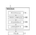
図25は、本実施形態における情報処理装置2301と印刷制御装置2420の機能的な構成の一例を示すブロック図である。情報処理装置2301と、画像処理装置2520は、ネットワークを介して相互に接続されている。以下に、印刷処理を実行する際の画像処理システムにおける動作の一例を説明する。 FIG. 25 is a block diagram illustrating an example of functional configurations of the
アプリケーションプログラム2511は、印刷動作が起動すると、XAML形式の印刷データ2512を作成する。ここで生成されるXAML形式の印刷データ2512は、従来のGDI(Graphic Device Interface)形式の印刷データと同様のものである。XAML形式の印刷データ2512が作成されると、ページ割り振りスレッド2513は、印刷データ2512を解析する。そして、処理の内容や並行処理性等を考慮して、印刷データ2512の領域を分割し、分割した印刷データ2512を、PDL生成スレッド2514、2515に割り振る処理等を行う。 When the printing operation is started, the application program 2511 creates print data 2512 in XAML format. The XAML format print data 2512 generated here is the same as the conventional GDI (Graphic Device Interface) format print data. When print data 2512 in XAML format is created, the page allocation thread 2513 analyzes the print data 2512. Then, in consideration of processing contents, parallel processing performance, and the like, the area of the print data 2512 is divided, and the divided print data 2512 is allocated to the
このようにして印刷データ2512が割り振られると、PDL生成スレッド2514、2515は、割り触れられた印刷データからPDLデータを生成する。これらPDL生成スレッド2514、2515は、並行してPDLデータを生成する処理を行う。なお、PDL生成スレッド2514、2515は、PDLデータだけでなく、ホストコンピュータ2401側でイメージデータに展開されたデータを画像処理装置2420に送信することもできる。 When the print data 2512 is allocated in this way, the
PDL生成スレッド2514、2515によって生成されたPDLデータは、送信スレッド2516、2517によって画像処理装置2420に送信される。このPDLデータを送信する処理は、ページ割り振りスレッド2513によってスケジューリングされたネットワーク通信チャネルを用いて行われる。 PDL data generated by the
画像処理装置2420のネットワークインタフェース2421は、受信した印刷データを、その印刷データの種別に応じて、印刷制御メイン部2522へ転送するか、画像メモリ2523へ直接書き込むかを判断する。ネットワークインタフェース2421は、例えば、印刷データがPDLデータの場合には、その印刷データを印刷制御メイン部2522へ転送すると判断する。一方、印刷データがホストコンピュータ2401でイメージデータに展開されたデータ、又はネットワークインタフェース2421で簡単な画像処理を行わせるデータである場合には、その印刷データを画像メモリ2523へ直接書き込むと判断する。 The
印刷制御メイン部2522へ転送されたPDLデータは、印刷制御メイン部2522で画像処理が行われた後に、画像メモリ2523へ書き込まれ、印刷制御メイン部2522によるプリンタエンジン(画像形成装置2440)の制御によって印刷が実行される。
ネットワークインタフェース2421から画像メモリ2523へ直接書き込まれる印刷データは、ホストコンピュータ2401側でイメージデータに展開されたデータであるか、ネットワークインタフェース2421で簡単な画像処理を行わせるデータである。このような印刷データの場合には、ネットワークインタフェース2421で簡単な画像処理を行った結果を(印刷制御メイン部2522を介さずに)画像メモリ2523に書き込む。そして印刷制御メイン部2522によるプリンタエンジン(画像形成装置2440)の制御によって印刷が実行される。The PDL data transferred to the print control
The print data directly written to the
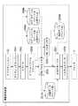
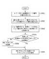
次に、図26のフローチャートを参照しながら、情報処理装置2301におけるプリンタドライバ2304の処理の一例を説明する。
まず、ステップS401において、印刷動作が起動すると、印刷を行うプリンタ2307から基本情報を獲得する。この基本情報の一例としては、プリンタ2307における画像形成用のメモリの容量や、印刷メイン制御部2522を構成するCPU2424の情報や、ネットワークインタフェース2421が使用可能なバッファメモリの容量のように、静的な情報である。これらの基本情報に基づいて、プリンタドライバ2304は、自身の行うべき処理を切り替えることになる。Next, an example of processing of the printer driver 2304 in the
First, in step S401, when a printing operation is activated, basic information is acquired from the
次に、ステップS402において、アプリケーションプログラム2303が出力した印刷データ(アプリケーションデータ)を解析する。そして、解析して得られた結果と、ステップS401で獲得した静的な基本情報とに基づいて、印刷時間を短縮する上で効果がでるように印刷データの分類を行う。この分類により、情報処理装置2301と、印刷制御装置2420との間における負荷の分散を図った上で、情報処理装置2301側ではマルチスレッドによって、分類された印刷データを並行して処理することができる。 In step S402, the print data (application data) output by the application program 2303 is analyzed. Based on the result obtained by the analysis and the static basic information acquired in step S401, the print data is classified so as to be effective in shortening the printing time. With this classification, load distribution between the
次に、ステップS403において、プリンタ2307から、動的に変化する動的情報を獲得する。この動的情報の一例としては、画像形成用のメモリにおける実際の空き容量や、CPU2424の負荷情報や、印刷中のステイタス進行情報等である。
次に、ステップS404において、各スレッドが分担する処理を決定し、ステップS405において、処理を分担して行うマルチスレッドを起動する。なお、分担する処理と共に、後述する送信処理において使用するチャネルについてもこのステップS404で決定しておく。Next, in step S403, dynamically changing dynamic information is acquired from the
Next, in step S404, a process to be shared by each thread is determined, and in step S405, a multi-thread that performs the process in common is activated. Note that, in addition to the shared processing, the channels used in the transmission processing described later are also determined in step S404.
そして、ステップS406〜S409において、いくつかの画像処理を同時に並行して行い、その結果としてPDLデータやホストスケーリングデータが生成される。さらに、ステップS410〜S413において、マルチスレッドにより、ネットワーク2415を介して印刷制御装置2420へ並行して、PDLデータやホストスケーリングデータが送信される。 In steps S406 to S409, several image processes are simultaneously performed in parallel, and as a result, PDL data and host scaling data are generated. Further, in steps S410 to S413, PDL data and host scaling data are transmitted in parallel to the
次に、ステップS414において、1ページ中の全ての領域で処理が終了したか否かを判定する。この判定の結果、1ページ中の全ての領域で処理が終了していなければステップS403に戻り、1ページ中の全ての領域で処理が終了するまでステップS403〜S414を繰り返し行う。
1ページ中の全ての領域で処理が終了すると、ステップS415に進み、全てのページで処理が終了したか否かを判定する。この判定の結果、全てのページで処理が終了していなければ、ステップS402に戻り、次のページへの処理に進み、全てのページで処理が終了するまでステップS402〜S415を繰り返し行う。一方、全てのページで処理が終了したなら、印刷処理は終了となる。Next, in step S414, it is determined whether or not processing has been completed for all areas in one page. If the result of this determination is that processing has not been completed for all areas in one page, the process returns to step S403, and steps S403 to S414 are repeated until processing has been completed for all areas in one page.
When the process is completed for all areas in one page, the process proceeds to step S415, and it is determined whether the process is completed for all pages. If the result of this determination is that processing has not been completed for all pages, processing returns to step S402, processing proceeds to the next page, and steps S402 to S415 are repeated until processing is completed for all pages. On the other hand, if the process is completed for all pages, the printing process is terminated.
なお、以上の説明では、1ページをある領域に分割し、分割した領域を分担してマルチスレッドで処理するようにしたが、領域単位で分割するのではなく、オブジェクト単位で分割することも可能である。その場合には、例えば、オブジェクトの重なり合いの情報を用いて、重ね合わせる順番を考慮したり、ページ情報を用いて各ページの構成を考慮したりする必要がある。 In the above description, one page is divided into a certain area, and the divided area is shared and processed by multithreading. However, it is possible to divide by page instead of dividing by area. It is. In that case, for example, it is necessary to consider the order of superimposition using the information on the overlap of objects, or to consider the configuration of each page using page information.
次に、図27のフローチャートを参照しながら、印刷制御装置2420におけるネットワークインタフェース2421の処理の一例について説明する。
まず、ステップS501において、ネットワーク2415からデータを受信するまで待機する。データの受信があると、ステップS502に進み、受信したデータのプロトコルを解析し、そのデータの中身を解析する。受信したデータは、通常、何らかのコマンド形式で記述がされている。Next, an example of processing of the
First, in step S501, the process waits until data is received from the
次に、ステップS503において、受信したデータが、印刷で使用するNIC(Network Information Card)に専用のチャネルを設定するコマンドか否かを判定する。この判定の結果、受信したデータが、印刷で使用するNICに専用のチャネルを設定するコマンドである場合には、それ以降で使用するチャネルについての情報が指定されているので、ステップS504に進む。そして、ステップS504において、そのチャネルが使用できるように専用のチャネルを設定した後、ステップS501に戻り次のパケット処理に移る。このステップS504では、具体的に、ある番号のTCP(Transmission Control Protocol)ポート番号に対して、LISTENするようにする。さらに、印刷で使用するNICに専用のチャネルを設定するコマンドにはNICで行う機能についての指定がある。したがって、NICで受信されたデータに対してその指定された機能に基づく処理が適用される。 In step S503, it is determined whether the received data is a command for setting a dedicated channel for a NIC (Network Information Card) used for printing. As a result of this determination, if the received data is a command for setting a channel dedicated to the NIC used for printing, information on the channel to be used thereafter is designated, and the process proceeds to step S504. In step S504, after setting a dedicated channel so that the channel can be used, the process returns to step S501 and proceeds to the next packet processing. In step S504, specifically, a LISTEN is performed for a certain TCP (Transmission Control Protocol) port number. Further, a command for setting a channel dedicated to the NIC used for printing includes designation of a function performed by the NIC. Therefore, processing based on the designated function is applied to data received by the NIC.
一方、受信したデータが、印刷で使用するNICに専用のチャネルを設定するコマンドでない場合には、ステップS505に進み、受信したデータが、ステップS504で設定された専用のチャネルへの印刷データか否かを判定する。この判定の結果、受信したデータが、ステップS504で設定された専用のチャネルへの印刷データである場合には、その専用のチャネルに割り付けられた機能で処理を行う(ステップS506〜S510)。ここではメモリ転送処理と簡易画像処理について説明する。 On the other hand, if the received data is not a command for setting a dedicated channel for the NIC used for printing, the process proceeds to step S505, and whether or not the received data is print data for the dedicated channel set in step S504. Determine whether. As a result of this determination, if the received data is print data for the dedicated channel set in step S504, processing is performed using the function assigned to the dedicated channel (steps S506 to S510). Here, the memory transfer process and the simple image process will be described.
ステップS506において、受信したデータが、メモリ転送処理用のデータか否かを判定する。この判定の結果、受信したデータが、メモリ転送処理用のデータの場合には、ステップS507に進み、メモリ転送処理を行う。このメモリ転送処理では、受信したデータに含まれている画像用メモリアドレス情報に基づくメモリ領域(画像メモリ2523)に、受信したデータに含まれているイメージデータを直接書き込む。このように、印刷メイン制御部2522を構成するCPU2424を介することなくイメージデータの書き込みを可能とすることによって、CPU2424への負担を増やさないことが可能である。 In step S506, it is determined whether the received data is data for memory transfer processing. As a result of this determination, if the received data is data for memory transfer processing, the process proceeds to step S507, and memory transfer processing is performed. In this memory transfer process, the image data included in the received data is directly written into the memory area (image memory 2523) based on the image memory address information included in the received data. As described above, by allowing image data to be written without going through the
ステップS506において、受信したデータが、メモリ転送処理用のデータでない場合には、ステップS508に進み、受信したデータが、簡易画像処理用のデータであるか否かを判定する。この判定の結果、受信したデータが、簡易画像処理用のデータである場合には、ステップS509に進み、簡易画像処理を行う。この簡易画像処理では、受信したデータのコマンドを解析し、解析した結果に応じた画像処理を行う。例えば、圧縮されたデータを伸長する。そして、ステップS510において、ステップS509で画像処理したデータを画像メモリ2523へ書き込む。NICのCPUで可能であるような画像処理をネットワークインタフェース2421で行うことで、転送するイメージデータの量を圧縮して通信速度を向上させることが可能となると共に、CPUの負荷を増やさないようにすることが可能となる。 If it is determined in step S506 that the received data is not memory transfer processing data, the process advances to step S508 to determine whether the received data is simple image processing data. As a result of the determination, if the received data is data for simple image processing, the process proceeds to step S509 and simple image processing is performed. In this simple image processing, the received data command is analyzed, and image processing according to the analysis result is performed. For example, the compressed data is decompressed. In step S510, the data processed in step S509 is written into the
ステップS505において、受信したデータが、ステップS504で設定された専用のチャネルへの印刷データでないと判定された場合には、ステップS511に進む。ステップS511では、受信したデータが、NIC内で処理することが可能なデータであるか否かを判定する。例えば、受信したデータが、MIB(Management Information Base)か否かを判定する。この判定の結果、受信したデータが、NIC内で処理することが可能なデータである場合には、ステップS512に進み、受信したデータをNICに転送すると共に、NICからの要求に応じて必要なデータをNICに出力する。 If it is determined in step S505 that the received data is not print data for the dedicated channel set in step S504, the process proceeds to step S511. In step S511, it is determined whether the received data is data that can be processed in the NIC. For example, it is determined whether the received data is MIB (Management Information Base). As a result of the determination, if the received data is data that can be processed in the NIC, the process proceeds to step S512, and the received data is transferred to the NIC and is necessary in response to a request from the NIC. Data is output to the NIC.
一方、受信したデータが、NIC内で処理することが可能なデータでない場合には、ステップS513に進み、受信したデータが、PDLデータか否かを判定する。この判定の結果、受信したデータが、PDLデータである場合には、ステップS514に進み、受信したデータを印刷制御メイン部2522に転送する。
一方、受信したデータが、PDLデータでない場合には、ステップS515に進み、受信したデータが、プリンタ2307のステイタス情報の取得コマンドか否かを判定する。この判定の結果、受信したデータが、プリンタ2307のステイタス情報の取得コマンドである場合には、ステップS516に進む。ステップS615では、印刷制御メイン部2522と通信を行って、動的に変化する動的情報を取得し、取得した動的情報を情報処理装置2301へ返信する。On the other hand, if the received data is not data that can be processed in the NIC, the process advances to step S513 to determine whether the received data is PDL data. If it is determined that the received data is PDL data, the process advances to step S514 to transfer the received data to the print control
On the other hand, if the received data is not PDL data, the process advances to step S515 to determine whether or not the received data is a status information acquisition command of the
次に、図28のフローチャートを参照しながら、印刷制御装置2420の処理の一例を説明する。
まず、ステップS601において、ネットワークインタフェース2421は、ネットワーク2415からデータを受信するまで待機する。データを受信した場合には、ステップS602に進み、ネットワークインタフェース2421は、その受信したデータを解析する。そして、受信したデータが、画像処理コマンドか、それともプリンタ制御コマンドかを判定する。Next, an example of processing of the
First, in step S601, the
この判定の結果、受信したデータが画像処理コマンドであれば、ステップS603に進む。ステップS603において、印刷制御メイン部2522又はネットワークインタフェース2421は、受信したデータが、メモリ転送処理用のデータであるか、それとも簡易画像処理用のデータであるかに応じて、処理を行う。そして、最終的に、受信したデータを画像メモリ2523でイメージデータに展開する。そして、展開されたイメージデータの印刷が行われる。 If it is determined that the received data is an image processing command, the process advances to step S603. In step S603, the print control
次に、ステップS604において、ネットワークインタフェース2421は、NICに専用のチャネルによる処理が完了しているか否かを判定する。この判定の結果、NICに専用のチャネルによる処理が完了していなければ、ステップS605に進み、ネットワークインタフェース2421は、ウェイトする等して、最終的な印刷処理を完了できるようにするための制御を行う。
次に、ステップS605において、印刷制御メイン部2522は、プリンタエンジン(画像形成装置2440)の制御によって印刷を実行する。Next, in step S604, the
In step S605, the print control
ステップS602において、受信したデータが、プリンタ制御コマンドであると判定した場合には、プリンタ2307の設定やプリンタ2307のステイタス情報の返信等、受信したプリンタ制御コマンドに応じた処理を行い、ステップS601に戻る。 If it is determined in step S602 that the received data is a printer control command, processing according to the received printer control command, such as setting of the
以上のように本実施形態では、情報処理装置2301は、アプリケーションプログラム2303が出力した印刷データの解析内容と、プリンタ2307から取得した基本情報とに基づいて印刷データの領域を分割し、分割した印刷データを分類する。そして、プリンタ2307から取得した動的情報に基づいて、マルチスレッドの各スレッドが分担する処理を決定する。各スレッドは、決定された処理を並行して行い、PDLデータやホストスケーリングデータ(例えば、前記メモリ転送処理用のデータや前記簡易画像処理用のデータ)を生成する。そして、生成したPDLデータやホストスケーリングデータを、複数チャネルを利用して並行してプリンタ2307に送信する。以上のようにすることにより、情報処理装置2301で印刷データを効率よく生成することができ、印刷に要する時間を短縮することが可能になる。 As described above, in this embodiment, the
また、プリンタ2307側の印刷制御装置2420のネットワークインタフェース2421は、情報処理装置2301から送信された印刷データが、PDLデータの場合には、その印刷データを印刷制御メイン部2522へ転送する。そして、印刷制御メイン部2522で画像処理を行わせる。一方、情報処理装置2301から送信された印刷データが、ホストコンピュータ2401でイメージデータに展開されたデータ等のホストスケーリングデータの場合には、ネットワークインタフェース2421でそのデータの画像処理を行う。以上のようにすることにより、情報処理装置2301が生成した印刷データを効率よく通信処理することができ、印刷に要する時間を短縮することが可能になる。 In addition, when the print data transmitted from the
(本発明の他の実施形態)
上述した実施形態の機能を実現するべく各種のデバイスを動作させるように、該各種デバイスと接続された装置あるいはシステム内のコンピュータに対し、前記実施形態の機能を実現するためのソフトウェアのプログラムコードを供給する。そして、そのシステムあるいは装置のコンピュータ(CPUあるいはMPU)に格納されたプログラムに従って前記各種デバイスを動作させることによって実施したものも、本発明の範疇に含まれる。(Other embodiments of the present invention)
In order to operate various devices to realize the functions of the above-described embodiments, program codes of software for realizing the functions of the above-described embodiments are provided to an apparatus or a computer in the system connected to the various devices. Supply. And what was implemented by operating the said various devices according to the program stored in the computer (CPU or MPU) of the system or apparatus is also contained under the category of the present invention.
また、この場合、前記ソフトウェアのプログラムコード自体が上述した実施形態の機能を実現することになる。また、そのプログラムコード自体、及びそのプログラムコードをコンピュータに供給するための手段、例えば、かかるプログラムコードを格納した記録媒体は本発明を構成する。かかるプログラムコードを記憶する記録媒体としては、例えばフレキシブルディスク、ハードディスク、光ディスク、光磁気ディスク、CD−ROM、磁気テープ、不揮発性のメモリカード、ROM等を用いることができる。 In this case, the program code of the software itself realizes the functions of the above-described embodiment. The program code itself and means for supplying the program code to a computer, for example, a recording medium storing the program code constitute the present invention. As a recording medium for storing the program code, for example, a flexible disk, a hard disk, an optical disk, a magneto-optical disk, a CD-ROM, a magnetic tape, a nonvolatile memory card, a ROM, or the like can be used.
また、コンピュータが供給されたプログラムコードを実行することにより、上述の実施形態の機能が実現される。さらに、そのプログラムコードがコンピュータにおいて稼働しているOS(オペレーティングシステム)あるいは他のアプリケーションソフト等と共同して上述の実施形態の機能が実現される場合にもかかるプログラムコードは本発明の実施形態に含まれることは言うまでもない。 Moreover, the function of the above-described embodiment is realized by executing the program code supplied by the computer. Further, when the program code is implemented in cooperation with an OS (operating system) or other application software running on the computer, the program code is also included in the embodiment of the present invention. Needless to say, it is included.
さらに、供給されたプログラムコードがコンピュータの機能拡張ボードやコンピュータに接続された機能拡張ユニットに備わるメモリに格納された後、そのプログラムコードの指示に基づいてその機能拡張ボードや機能拡張ユニットに備わるCPU等が実際の処理の一部または全部を行う。その処理によって上述した実施形態の機能が実現される場合にも本発明に含まれることは言うまでもない。 Further, after the supplied program code is stored in the memory provided in the function expansion board of the computer or the function expansion unit connected to the computer, the CPU provided in the function expansion board or function expansion unit based on the instruction of the program code Etc. perform part or all of the actual processing. Needless to say, the present invention includes the case where the functions of the above-described embodiments are realized by the processing.
なお、前述した各実施形態は、何れも本発明を実施するにあたっての具体化の例を示したものに過ぎず、これらによって本発明の技術的範囲が限定的に解釈されてはならないものである。すなわち、本発明はその技術思想、またはその主要な特徴から逸脱することなく、様々な形で実施することができる。 Note that each of the above-described embodiments is merely a specific example for carrying out the present invention, and the technical scope of the present invention should not be construed as being limited thereto. . That is, the present invention can be implemented in various forms without departing from the technical idea or the main features thereof.
1、2301 情報処理装置
2、2307 プリンタ
32、2201 アプリケーションプログラム
1902 グラフィックエンジン
1904 システムスプーラ
2003 スプーラ
2004 スプールファイルマネージャ
2005、2006 PDLプロセッサ
2007 出力マネージャ
2009 スプールファイル
2010 印刷データファイル
2203 プロセッサマネージャ
2209 印刷要求ファイル
2421 ネットワークインタフェース
2513 ページ割り振りスレッド
2514、2515 PDL生成スレッド
2516、2517 送信スレッド
2522 印刷制御メイン部
2523 画像メモリ1, 2301
Claims (17)
Translated fromJapanese前記割り当て手段により複数の領域のデータが割り当てられた複数の処理手段で並行して処理して複数の印刷コマンドを生成する印刷コマンド生成手段と、
前記印刷コマンド生成手段により生成された複数の印刷コマンドを、印刷装置に出力する出力手段とを有し、
前記出力手段は、前記印刷コマンド生成手段により生成された複数の印刷コマンドを、印刷順とは無関係に生成された順で、印刷装置に出力することを特徴とする情報処理装置。Assigning means for assigning data of a plurality of areas included in a print job to any of a plurality of processing means independent of each other;
Print command generating means for generating a plurality of print commands by processing in parallel by a plurality of processing means to which data of a plurality of areas are assigned by the assigning means;
A plurality of print command generated by the print command generating means,have a output means for outputting to the printingdevice,
The information processing apparatus, wherein the output unit outputs a plurality of print commands generated by the print command generation unit to a printing apparatus in an order generated regardless of a printing order .
前記割り当て手段により複数の領域のデータが割り当てられた複数の処理手段で並行して処理して複数の印刷コマンドを生成する印刷コマンド生成手段と、
前記印刷コマンド生成手段により生成された複数の印刷コマンドを、印刷装置に出力する出力手段と、
前記印刷コマンド生成手段により生成された複数の印刷コマンドに、前記印刷装置における出力順を識別するための識別情報を付加する識別情報付加手段とを有し、
前記出力手段は、前記識別情報付加手段により識別情報が付加された複数の印刷コマンドを、前記印刷装置における出力順とは無関係に、生成順に前記印刷装置に出力することを特徴とする情報処理装置。Assigning means for assigning data of a plurality of areas included in a print job to any of a plurality of processing means independent of each other;
Print command generating means for generating a plurality of print commands by processing in parallel by a plurality of processing means to which data of a plurality of areas are assigned by the assigning means;
Output means for outputting a plurality of print commands generated by the print command generation means to a printing apparatus;
Wherein the print command plurality of print command generated by the generating means, andan identification information adding means for adding identification information for identifying the output order in the printing device,
And the output means, the identification information adding means multiple print command identification information is added by, regardless of the output order of the printing apparatus,information you and outputs the generated order of the printing device Processing equipment.
前記取得手段により取得された情報に基づいて、各スレッドの担当する処理を決定し、決定した処理を各スレッドに割り当てる割り当て手段と、
前記割り当て手段により処理が割り当てられた複数のスレッドを並行して処理して複数の印刷コマンドを生成する印刷コマンド生成手段と、
前記印刷コマンド生成手段により生成された複数の印刷コマンドを、複数のスレッドで並行して印刷制御装置に出力する出力手段とを有し、
前記出力手段は、前記印刷コマンド生成手段により生成された複数の印刷コマンドを、印刷順とは無関係に生成された順で、印刷装置に出力することを特徴とする情報処理装置。Obtaining means for obtaining dynamically changing information of the printing apparatus;
An assigning unit that determines a process in charge of each thread based on the information acquired by the acquiring unit, and assigns the determined process to each thread;
Print command generating means for processing a plurality of threads assigned processing by the assigning means in parallel to generate a plurality of print commands;
A plurality of print command generated by the print command generating means,have a output means for outputting the print control apparatus in parallel in multiplethreads,
The information processing apparatus, wherein the output unit outputs a plurality of print commands generated by the print command generation unit to a printing apparatus in an order generated regardless of a printing order .
前記情報処理装置から出力された印刷コマンドを画像処理して画像メモリに書き込む制御手段と、
前記情報処理装置から出力された印刷コマンドが、前記制御手段により画像処理される必要があるものか否かを判定する判定手段と、
前記判定手段により画像処理される必要がないと判定された印刷コマンドを前記画像メモリに書き込む書きこみ手段とを有し、
前記制御手段は、前記判定手段により画像処理される必要があると判定された印刷コマンドを画像処理して前記画像メモリに出力することを特徴とする印刷制御装置。Is communicably connected to the information processing apparatus according to claim 11, using a printing command outputted from said information processing apparatus, a print control apparatus for controlling the printing device,
Control means for performing image processing on the print command output from the information processing apparatus and writing it to an image memory;
Determination means for determining whether a print command output from the information processing apparatus needs to be image-processed by the control means;
Writing means for writing in the image memory a print command determined not to be image-processed by the determination means;
The print control apparatus, wherein the control unit performs image processing on a print command determined to be image-processed by the determination unit and outputs the print command to the image memory.
前記割り当てステップにより複数の領域のデータが割り当てられた複数の処理手段で並行して処理して複数の印刷コマンドを生成する印刷コマンド生成ステップと、
前記印刷コマンド生成ステップにより生成された複数の印刷コマンドを、印刷装置に出力する出力ステップとを有し、
前記出力ステップは、前記印刷コマンド生成ステップにより生成された複数の印刷コマンドを、印刷順とは無関係に生成された順で、印刷装置に出力することを特徴とする画像処理方法。An assigning step of assigning data of a plurality of areas included in the print job to any of a plurality of processing means independent of each other;
A print command generation step of generating a plurality of print commands by processing in parallel by a plurality of processing means to which data of a plurality of areas are allocated by the allocation step;
A plurality of print command generated by the print command generation step,possess an output step of outputting to the printingdevice,
The image processing method according toclaim 1, wherein the output step outputs the plurality of print commands generated by the print command generation step to a printing apparatus in the order generated regardless of the print order .
前記取得ステップにより取得された情報に基づいて、各スレッドの担当する処理を決定し、決定した処理を各スレッドに割り当てる割り当てステップと、
前記割り当てステップにより処理が割り当てられた複数のスレッドを並行して処理して複数の印刷コマンドを生成する印刷コマンド生成ステップと、
前記印刷コマンド生成ステップにより生成された複数の印刷コマンドを、複数のスレッドで並行して印刷制御装置に出力する出力ステップとを有し、
前記出力ステップは、前記印刷コマンド生成ステップにより生成された複数の印刷コマンドを、印刷順とは無関係に生成された順で、印刷装置に出力することを特徴とする画像処理方法。An acquisition step of acquiring dynamically changing information of the printing device;
An assigning step of determining a process in charge of each thread based on the information acquired by the acquiring step, and assigning the determined process to each thread;
A print command generation step for generating a plurality of print commands by processing a plurality of threads to which processing is assigned in the assignment step in parallel;
A plurality of print command generated by the print command generation step,possess an output step of outputting the parallel print control apparatus in a plurality ofthreads,
The image processing method according toclaim 1, wherein the output step outputs the plurality of print commands generated by the print command generation step to a printing apparatus in the order generated regardless of the print order .
前記出力ステップにより出力された印刷コマンドが、前記制御ステップにより画像処理される必要があるものか否かを判定する判定ステップと、
前記判定ステップにより画像処理される必要がないと判定された印刷コマンドを前記画像メモリに書き込む書きこみステップとを有し、
前記制御ステップは、前記判定ステップにより画像処理される必要があると判定された印刷コマンドを画像処理して前記画像メモリに出力することを特徴とする請求項14に記載の画像処理方法。A control step of performing image processing on the print command output by the output step and writing it to an image memory;
A determination step for determining whether the print command output by the output step needs to be image-processed by the control step;
A writing step of writing a print command determined to be unnecessary for image processing in the determination step to the image memory;
The control step, the image processing method according to claim 14, characterized in that said determining a print command is determined to be necessary to be image processed by the image processing in step outputs to the image memory.
前記割り当てステップにより複数の領域のデータが割り当てられた複数の処理手段で並行して処理して複数の印刷コマンドを生成する印刷コマンド生成ステップと、
前記印刷コマンド生成ステップにより生成された複数の印刷コマンドを、印刷装置に出力する出力ステップとをコンピュータに実行させ、
前記出力ステップは、前記印刷コマンド生成ステップにより生成された複数の印刷コマンドを、印刷順とは無関係に生成された順で、印刷装置に出力することを特徴とするコンピュータプログラム。An assigning step of assigning data of a plurality of areas included in the print job to any of a plurality of processing means independent of each other;
A print command generation step of generating a plurality of print commands by processing in parallel by a plurality of processing means to which data of a plurality of areas are allocated by the allocation step;
Causing a computer to execute an output step of outputting a plurality of print commands generated by the print command generation step to a printing apparatus;
It said output step, the printing of multiple generated by the command generation step print command, in the order that is generated independently from the printing order, the computer program characterized alsobe output fromthe printing device.
前記取得ステップにより取得された情報に基づいて、各スレッドの担当する処理を決定し、決定した処理を各スレッドに割り当てる割り当てステップと、
前記割り当てステップにより処理が割り当てられた複数のスレッドを並行して処理して複数の印刷コマンドを生成する印刷コマンド生成ステップと、
前記印刷コマンド生成ステップにより生成された複数の印刷コマンドを、複数のスレッドで並行して印刷制御装置に出力する出力ステップとをコンピュータに実行させ、
前記出力ステップは、前記印刷コマンド生成ステップにより生成された複数の印刷コマンドを、印刷順とは無関係に生成された順で、印刷装置に出力することを特徴とするコンピュータプログラム。An acquisition step of acquiring dynamically changing information of the printing device;
An assigning step of determining a process in charge of each thread based on the information acquired by the acquiring step, and assigning the determined process to each thread;
A print command generation step for generating a plurality of print commands by processing a plurality of threads to which processing is assigned in the assignment step in parallel;
Causing the computer to execute an output step of outputting the plurality of print commands generated by the print command generation step to the print control apparatus in parallel by a plurality of threads;
It said output step, the printing of multiple generated by the command generation step print command, in the order that is generated independently from the printing order, the computer program characterized alsobe output fromthe printing device.
Priority Applications (3)
| Application Number | Priority Date | Filing Date | Title |
|---|---|---|---|
| JP2005265908AJP4738948B2 (en) | 2005-09-13 | 2005-09-13 | Information processing apparatus, image processing method, and computer program |
| US11/468,191US20070070403A1 (en) | 2005-09-13 | 2006-08-29 | Information processing apparatus, information processing method, and program |
| CNB2006101518916ACN100389385C (en) | 2005-09-13 | 2006-09-13 | Information processing apparatus, information processing method, and program |
Applications Claiming Priority (1)
| Application Number | Priority Date | Filing Date | Title |
|---|---|---|---|
| JP2005265908AJP4738948B2 (en) | 2005-09-13 | 2005-09-13 | Information processing apparatus, image processing method, and computer program |
Publications (3)
| Publication Number | Publication Date |
|---|---|
| JP2007079854A JP2007079854A (en) | 2007-03-29 |
| JP2007079854A5 JP2007079854A5 (en) | 2008-10-30 |
| JP4738948B2true JP4738948B2 (en) | 2011-08-03 |
Family
ID=37878599
Family Applications (1)
| Application Number | Title | Priority Date | Filing Date |
|---|---|---|---|
| JP2005265908AExpired - Fee RelatedJP4738948B2 (en) | 2005-09-13 | 2005-09-13 | Information processing apparatus, image processing method, and computer program |
Country Status (3)
| Country | Link |
|---|---|
| US (1) | US20070070403A1 (en) |
| JP (1) | JP4738948B2 (en) |
| CN (1) | CN100389385C (en) |
Families Citing this family (16)
| Publication number | Priority date | Publication date | Assignee | Title |
|---|---|---|---|---|
| JP2007060505A (en)* | 2005-08-26 | 2007-03-08 | Fuji Xerox Co Ltd | Image reading device, image processing method, image formation apparatus, image processing system and its printing time shortening method |
| JP5393343B2 (en)* | 2009-08-21 | 2014-01-22 | キヤノン株式会社 | Print data processing apparatus, print data processing method, and program |
| JP5675082B2 (en)* | 2009-11-26 | 2015-02-25 | キヤノン株式会社 | Printing apparatus and processing method thereof |
| JP2011126210A (en)* | 2009-12-18 | 2011-06-30 | Canon Inc | Printing data processor, print data processing method, and program |
| JP5663941B2 (en)* | 2010-04-30 | 2015-02-04 | 富士ゼロックス株式会社 | Printed document conversion apparatus and program |
| JP5655392B2 (en)* | 2010-06-23 | 2015-01-21 | 富士ゼロックス株式会社 | Print image processing apparatus and program |
| JP4947231B1 (en)* | 2011-09-20 | 2012-06-06 | 富士ゼロックス株式会社 | Print control apparatus and program |
| JP5919938B2 (en)* | 2012-03-26 | 2016-05-18 | 富士ゼロックス株式会社 | Information processing system and program |
| JP5273420B1 (en)* | 2012-10-11 | 2013-08-28 | 富士ゼロックス株式会社 | Print control apparatus, image forming system, and program |
| JP5464283B2 (en)* | 2013-01-08 | 2014-04-09 | カシオ電子工業株式会社 | Print data processing method |
| JP6044394B2 (en)* | 2013-03-01 | 2016-12-14 | コニカミノルタ株式会社 | Job processing apparatus, job control method, and computer program |
| AU2013276977A1 (en)* | 2013-12-24 | 2015-07-09 | Canon Kabushiki Kaisha | Asynchronous group processing using z-banding |
| JP2019526475A (en)* | 2016-09-09 | 2019-09-19 | ヒューレット−パッカード デベロップメント カンパニー エル.ピー.Hewlett‐Packard Development Company, L.P. | Print zone adjustment |
| CN107580049A (en)* | 2017-09-05 | 2018-01-12 | 同程网络科技股份有限公司 | A kind of expansible efficient APP channels bag packing platform |
| JP7006288B2 (en)* | 2018-01-16 | 2022-01-24 | ブラザー工業株式会社 | Programs and communication modules |
| CN115079965B (en)* | 2022-06-30 | 2024-11-26 | 龙芯中科技术股份有限公司 | Printing main control chip and printing method |
Family Cites Families (17)
| Publication number | Priority date | Publication date | Assignee | Title |
|---|---|---|---|---|
| US6657741B1 (en)* | 1995-08-07 | 2003-12-02 | Tr Systems, Inc. | Multiple print engine system with selectively distributed ripped pages |
| JP3175620B2 (en)* | 1996-06-21 | 2001-06-11 | セイコーエプソン株式会社 | Printing equipment |
| US6665081B1 (en)* | 1996-07-19 | 2003-12-16 | Seiko Epson Corporation | Print system printer driver and printer |
| JPH10289066A (en)* | 1997-04-11 | 1998-10-27 | Canon Inc | Image processing apparatus and method |
| JP2000112684A (en)* | 1998-09-30 | 2000-04-21 | Ricoh Co Ltd | Document print processing system |
| JP3797013B2 (en)* | 1999-04-12 | 2006-07-12 | セイコーエプソン株式会社 | Image processing method, printing apparatus, image processing system, and recording medium |
| EP1191434A4 (en)* | 2000-04-07 | 2003-07-09 | Seiko Epson Corp | CONTROL OF DISTRIBUTED PRINTERS |
| JP2002099393A (en)* | 2000-09-22 | 2002-04-05 | Minolta Co Ltd | Device and method for transmitting data and computer- readable recording medium with data transmission program recorded thereon |
| JP2003067154A (en)* | 2001-08-29 | 2003-03-07 | Ricoh Co Ltd | Print control method and printer device |
| JP3826038B2 (en)* | 2002-01-17 | 2006-09-27 | キヤノン株式会社 | Printing system, printing method therefor, and printing apparatus |
| WO2004009362A1 (en)* | 2002-07-19 | 2004-01-29 | Seiko Epson Corporation | Printing system |
| JP2004334513A (en)* | 2003-05-07 | 2004-11-25 | Canon Inc | Multithread decision processing method and apparatus in SoftRIP and storage medium for storing them |
| US7861156B2 (en)* | 2003-05-29 | 2010-12-28 | Electronics For Imaging, Inc. | Methods and apparatus for parallel processing page description language data |
| CN1282085C (en)* | 2004-04-09 | 2006-10-25 | 中兴通讯股份有限公司 | A Method for Multi-task Concurrent Debugging of Embedded System |
| JP4208776B2 (en)* | 2004-06-25 | 2009-01-14 | キヤノン株式会社 | Print client, network printer and printing system |
| US8368910B2 (en)* | 2004-07-23 | 2013-02-05 | Canon Kabushiki Kaisha | Printing apparatus and method |
| JP4207864B2 (en)* | 2004-08-10 | 2009-01-14 | ブラザー工業株式会社 | State information processing apparatus and data processing program for state information processing apparatus |
- 2005
- 2005-09-13JPJP2005265908Apatent/JP4738948B2/ennot_activeExpired - Fee Related
- 2006
- 2006-08-29USUS11/468,191patent/US20070070403A1/ennot_activeAbandoned
- 2006-09-13CNCNB2006101518916Apatent/CN100389385C/ennot_activeExpired - Fee Related
Also Published As
| Publication number | Publication date |
|---|---|
| JP2007079854A (en) | 2007-03-29 |
| CN100389385C (en) | 2008-05-21 |
| US20070070403A1 (en) | 2007-03-29 |
| CN1932750A (en) | 2007-03-21 |
Similar Documents
| Publication | Publication Date | Title |
|---|---|---|
| JP4738948B2 (en) | Information processing apparatus, image processing method, and computer program | |
| JP3826038B2 (en) | Printing system, printing method therefor, and printing apparatus | |
| US7064849B1 (en) | Data processing apparatus adaptable to plural environments and data processing method | |
| US8625133B2 (en) | Print data processing apparatus, print data processing method, and storage medium | |
| JP4944682B2 (en) | PRINT CONTROL DEVICE, PRINT CONTROL METHOD, PROGRAM, AND STORAGE MEDIUM | |
| JP3630943B2 (en) | Information processing apparatus, print control method, print control system, and storage medium storing print control program | |
| US8767247B2 (en) | Print data generation device, print data generation method and computer-readable medium for controlling rasterization processing | |
| US8368907B2 (en) | Image forming apparatus and image forming system | |
| JP4418642B2 (en) | HOST DEVICE, PRINTING DEVICE, PRINTING SYSTEM HAVING THEM, PRINT CONTROL METHOD, AND PROGRAM THEREOF | |
| JP5857594B2 (en) | Distributed printing system and printing apparatus | |
| JP2011046034A (en) | Image processor, image processing method, image processing program, and recording medium | |
| JP2002014797A (en) | INFORMATION PROCESSING DEVICE, PRINT CONTROL DEVICE, ITS CONTROL METHOD, STORAGE MEDIUM, AND ITS CONTROL PROGRAM | |
| US7764394B2 (en) | Data processing apparatus, data processing method, and data processing program | |
| JP4095581B2 (en) | Information processing apparatus and control method thereof | |
| JP2005161819A (en) | Printing apparatus and printing control method | |
| US7027170B1 (en) | Printing control system for separation printing | |
| JP2018144372A (en) | Image forming apparatus, image forming apparatus control method, and program | |
| JP2006146716A (en) | Information processing apparatus, information processing method, program, and storage medium | |
| JP4054544B2 (en) | Information processing apparatus, information processing method, print control program, print processing apparatus, print processing method, and print processing program | |
| JP2005173639A (en) | Information processing apparatus, printing apparatus, printing system, information processing method, program, and recording medium | |
| JP2019006044A (en) | Printing system, image forming apparatus, reservation printing method, and program | |
| JP2018144361A (en) | Image formation apparatus, control method and program of image formation apparatus | |
| KR20230032927A (en) | Information processing apparatus, method of controlling information processing apparatus, and storage medium | |
| JP3056948B2 (en) | PRINTING APPARATUS, CONTROLLER THEREOF, AND METHOD OF CONTROLLING PRINTING APPARATUS | |
| JP2003122521A (en) | Printing system, information processing apparatus, drawing method thereof, program, and storage medium |
Legal Events
| Date | Code | Title | Description |
|---|---|---|---|
| A521 | Written amendment | Free format text:JAPANESE INTERMEDIATE CODE: A523 Effective date:20080911 | |
| A621 | Written request for application examination | Free format text:JAPANESE INTERMEDIATE CODE: A621 Effective date:20080911 | |
| A977 | Report on retrieval | Free format text:JAPANESE INTERMEDIATE CODE: A971007 Effective date:20101117 | |
| A131 | Notification of reasons for refusal | Free format text:JAPANESE INTERMEDIATE CODE: A131 Effective date:20101130 | |
| A521 | Written amendment | Free format text:JAPANESE INTERMEDIATE CODE: A523 Effective date:20110131 | |
| A01 | Written decision to grant a patent or to grant a registration (utility model) | Free format text:JAPANESE INTERMEDIATE CODE: A01 Effective date:20110419 | |
| A01 | Written decision to grant a patent or to grant a registration (utility model) | Free format text:JAPANESE INTERMEDIATE CODE: A01 | |
| A61 | First payment of annual fees (during grant procedure) | Free format text:JAPANESE INTERMEDIATE CODE: A61 Effective date:20110427 | |
| R150 | Certificate of patent or registration of utility model | Free format text:JAPANESE INTERMEDIATE CODE: R150 | |
| FPAY | Renewal fee payment (event date is renewal date of database) | Free format text:PAYMENT UNTIL: 20140513 Year of fee payment:3 | |
| LAPS | Cancellation because of no payment of annual fees |