JP4737496B2 - REPRODUCTION SYSTEM, REPRODUCTION DEVICE AND METHOD, RECORDING MEDIUM, AND PROGRAM - Google Patents
REPRODUCTION SYSTEM, REPRODUCTION DEVICE AND METHOD, RECORDING MEDIUM, AND PROGRAMDownload PDFInfo
- Publication number
- JP4737496B2 JP4737496B2JP2004198787AJP2004198787AJP4737496B2JP 4737496 B2JP4737496 B2JP 4737496B2JP 2004198787 AJP2004198787 AJP 2004198787AJP 2004198787 AJP2004198787 AJP 2004198787AJP 4737496 B2JP4737496 B2JP 4737496B2
- Authority
- JP
- Japan
- Prior art keywords
- binaural
- transmission device
- information transmission
- human body
- sound information
- Prior art date
- Legal status (The legal status is an assumption and is not a legal conclusion. Google has not performed a legal analysis and makes no representation as to the accuracy of the status listed.)
- Expired - Fee Related
Links
Images


Classifications
- G—PHYSICS
- G06—COMPUTING OR CALCULATING; COUNTING
- G06F—ELECTRIC DIGITAL DATA PROCESSING
- G06F3/00—Input arrangements for transferring data to be processed into a form capable of being handled by the computer; Output arrangements for transferring data from processing unit to output unit, e.g. interface arrangements
- G06F3/16—Sound input; Sound output
- G06F3/162—Interface to dedicated audio devices, e.g. audio drivers, interface to CODECs
- H—ELECTRICITY
- H04—ELECTRIC COMMUNICATION TECHNIQUE
- H04R—LOUDSPEAKERS, MICROPHONES, GRAMOPHONE PICK-UPS OR LIKE ACOUSTIC ELECTROMECHANICAL TRANSDUCERS; DEAF-AID SETS; PUBLIC ADDRESS SYSTEMS
- H04R1/00—Details of transducers, loudspeakers or microphones
- H04R1/10—Earpieces; Attachments therefor ; Earphones; Monophonic headphones
- H04R1/1041—Mechanical or electronic switches, or control elements
- G—PHYSICS
- G06—COMPUTING OR CALCULATING; COUNTING
- G06F—ELECTRIC DIGITAL DATA PROCESSING
- G06F3/00—Input arrangements for transferring data to be processed into a form capable of being handled by the computer; Output arrangements for transferring data from processing unit to output unit, e.g. interface arrangements
- G06F3/16—Sound input; Sound output
- G06F3/165—Management of the audio stream, e.g. setting of volume, audio stream path
- H—ELECTRICITY
- H04—ELECTRIC COMMUNICATION TECHNIQUE
- H04R—LOUDSPEAKERS, MICROPHONES, GRAMOPHONE PICK-UPS OR LIKE ACOUSTIC ELECTROMECHANICAL TRANSDUCERS; DEAF-AID SETS; PUBLIC ADDRESS SYSTEMS
- H04R29/00—Monitoring arrangements; Testing arrangements
- H04R29/001—Monitoring arrangements; Testing arrangements for loudspeakers
- H—ELECTRICITY
- H04—ELECTRIC COMMUNICATION TECHNIQUE
- H04R—LOUDSPEAKERS, MICROPHONES, GRAMOPHONE PICK-UPS OR LIKE ACOUSTIC ELECTROMECHANICAL TRANSDUCERS; DEAF-AID SETS; PUBLIC ADDRESS SYSTEMS
- H04R5/00—Stereophonic arrangements
- H04R5/04—Circuit arrangements, e.g. for selective connection of amplifier inputs/outputs to loudspeakers, for loudspeaker detection, or for adaptation of settings to personal preferences or hearing impairments
- H—ELECTRICITY
- H04—ELECTRIC COMMUNICATION TECHNIQUE
- H04R—LOUDSPEAKERS, MICROPHONES, GRAMOPHONE PICK-UPS OR LIKE ACOUSTIC ELECTROMECHANICAL TRANSDUCERS; DEAF-AID SETS; PUBLIC ADDRESS SYSTEMS
- H04R2460/00—Details of hearing devices, i.e. of ear- or headphones covered by H04R1/10 or H04R5/033 but not provided for in any of their subgroups, or of hearing aids covered by H04R25/00 but not provided for in any of its subgroups
- H04R2460/03—Aspects of the reduction of energy consumption in hearing devices
- H—ELECTRICITY
- H04—ELECTRIC COMMUNICATION TECHNIQUE
- H04R—LOUDSPEAKERS, MICROPHONES, GRAMOPHONE PICK-UPS OR LIKE ACOUSTIC ELECTROMECHANICAL TRANSDUCERS; DEAF-AID SETS; PUBLIC ADDRESS SYSTEMS
- H04R5/00—Stereophonic arrangements
- H04R5/033—Headphones for stereophonic communication
Landscapes
- Engineering & Computer Science (AREA)
- Physics & Mathematics (AREA)
- Acoustics & Sound (AREA)
- Signal Processing (AREA)
- Theoretical Computer Science (AREA)
- General Health & Medical Sciences (AREA)
- Health & Medical Sciences (AREA)
- Human Computer Interaction (AREA)
- Audiology, Speech & Language Pathology (AREA)
- General Engineering & Computer Science (AREA)
- General Physics & Mathematics (AREA)
- Multimedia (AREA)
- Otolaryngology (AREA)
- Headphones And Earphones (AREA)
- Telephone Function (AREA)
- Circuit For Audible Band Transducer (AREA)
Description
Translated fromJapanese本発明は再生システム、再生装置および方法、記録媒体、並びにプログラムに関し、特に、バッテリによる再生時間をより長くすることができるようにした再生システム、再生装置および方法、記録媒体、並びにプログラムに関する。The present invention relates to a reproduction system, a reproduction apparatus and method, a recording medium, and a program, and more particularly, to a reproduction system, reproduction apparatus and method, recording medium, and program that can extend the reproduction time by a battery.
昨今、CD(Compact Disc)やMD(Mini Disc)などを再生する携帯型音楽プレーヤが普及している。携帯型音楽プレーヤでは、バッテリにより、より長く再生できるようにすることが重要である。そのために、音楽を再生していない間は、携帯型音楽プレーヤの電源を停止しておくことが望ましい。 Recently, portable music players that play CDs (Compact Discs), MDs (Mini Discs), and the like have become widespread. In a portable music player, it is important to be able to play back longer by a battery. Therefore, it is desirable to turn off the power of the portable music player while music is not being played.
図1は、ヘッドホン11と音楽プレーヤ(携帯型音楽プレーヤ)12とからなる従来の再生システムを示す図である。 FIG. 1 is a diagram showing a conventional playback system including a headphone 11 and a music player (portable music player) 12.
ヘッドホン11は、人間の両耳に被せて装着され、ヘッドホンコード(図1のヘッドホン11と音楽プレーヤ12とを接続しているコード)を介して、後述する音楽プレーヤ12から供給される音声信号を音声に変換し、変換した音声を出力する。 The headphone 11 is worn over both ears of a human, and receives an audio signal supplied from the music player 12 (described later) via a headphone cord (a cord connecting the headphone 11 and the
音楽プレーヤ12は、例えば、CDまたはMDなどの記憶媒体から、音楽データを読み出し、読み出した音声データを基に、音声信号を再生し、ヘッドホンコードを介して、再生した音声信号をヘッドホン11に供給する。 For example, the
また、音楽プレーヤ12の電源の状態(電源モード)であるが、音楽プレーヤ12の電源がオンしている状態を通常モードと称し、一方、音楽プレーヤ12の操作入力および制御に要する部位のみに電源を供給し、音声の再生に要する部位の電源をオフしている状態を電源保持モードと称する。すなわち、音楽プレーヤ12の電源モードが通常モードである場合、音楽プレーヤ12の全体が、バッテリにより駆動されており、一方、音楽プレーヤ12の電源モードが電源保持モードである場合、音楽プレーヤ12は、ユーザからの操作を受け付けるのに必要な最小限の部分がバッテリにより駆動され、電力をより多く消費する音声の再生に要する部位がバッテリにより駆動されない。 In addition, although the
より具体的には、音楽プレーヤ12の電源モードが通常モードである場合、音楽プレーヤ12は、ヘッドホンコードを介して、音声信号をヘッドホン11に供給し、一方、音楽プレーヤ12の電源モードが電源保持モードである場合、音楽プレーヤ12は、ヘッドホンコードを介して、音声信号をヘッドホン11には供給しない。換言すれば、音楽プレーヤ12の電源モードが通常モードである場合、ユーザは、ヘッドホン11から音楽を聴くことができるが、一方、音楽プレーヤ12の電源モードが電源保持モードである場合、ユーザは、ヘッドホン11から音楽を聴くことはできない。 More specifically, when the power mode of the
また、音楽プレーヤ12には、再生、停止、ポーズ、早送り、巻き戻し、またはボリューム調節などの各種ボタンが設けられている。ユーザの操作により、音楽プレーヤ12の再生ボタンが押された場合、音楽プレーヤ12は、音声信号をヘッドホン11に供給し、さらに、ユーザの操作により、音楽プレーヤ12の停止ボタンが押された場合、音楽プレーヤ12は、音声信号のヘッドホン11への供給を停止する。 In addition, the
このようにして、音楽プレーヤ12に接続されたヘッドホン11を耳に装着したユーザは、音楽を聴くことができる。 In this way, a user wearing headphones 11 connected to the
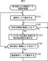
次に、図2のフローチャートを参照して、従来の再生システムの電源モードの変更の処理について説明する。 Next, a process for changing the power mode of the conventional reproduction system will be described with reference to the flowchart of FIG.
ステップS11において、音楽プレーヤ12は、音楽プレーヤ12の再生ボタンが押された場合、通常モードである電源モードで動作する。すなわち、音楽プレーヤ12は、ヘッドホンコードを介して、音声信号をヘッドホン11に供給する。この場合、ユーザは、ヘッドホン11を耳に装着して、音楽プレーヤ12が再生する音楽を聴くことができる。 In step S11, when the playback button of the
ステップS12において、音楽プレーヤ12は、ユーザの操作により、停止ボタンが押されたか否かを判定する。 In step S12, the
ステップS12において、ユーザの操作により、音楽プレーヤ12の停止ボタンが押されていないと判定された場合、音楽プレーヤ12の電源モードは、通常モードのままで、ステップS13に進み、音楽プレーヤ12は、ユーザの操作により、音楽プレーヤ12のポーズボタンが押されたか否かを判定する。 If it is determined in step S12 that the stop button of the
ステップS13において、ユーザの操作により、音楽プレーヤ12のポーズボタンが押されていないと判定された場合、音楽プレーヤ12の電源モードは、通常モードのままであるので、ステップS11に戻り、上述した処理を繰り返す。 If it is determined in step S13 that the pause button of the
一方、ステップS13において、ユーザの操作により、音楽プレーヤ12のポーズボタンが押されたと判定された場合、音楽プレーヤ12は、音声信号の再生をポーズして(一時停止して)、ステップS14に進み、音楽プレーヤ12は、ポーズしてから、所定の時間が経過したか否かを判定する。 On the other hand, if it is determined in step S13 that the pause button of the
ステップS14において、所定の時間が経過していないと判定された場合、ステップS14に戻り、所定の時間が経過するまで、上述した処理を繰り返す。 If it is determined in step S14 that the predetermined time has not elapsed, the process returns to step S14, and the above-described processing is repeated until the predetermined time has elapsed.
ステップS14において、所定の時間が経過したと判定された場合、ステップS15に進み、音楽プレーヤ12の電源モードは、通常モードから電源保持モードに移行する。すなわち、ユーザの操作により、音楽プレーヤ12のポーズボタンが押された場合、所定の時間が経過した後、音楽プレーヤ12の電源モードは、通常モードから電源保持モードへと移行する。このように、音楽プレーヤ12のポーズボタンが押されて、所定の時間が経過した場合、音楽プレーヤ12は電源をオフする。 If it is determined in step S14 that the predetermined time has elapsed, the process proceeds to step S15, and the power mode of the
ステップS12において、ユーザの操作により、音楽プレーヤ12の停止ボタンが押されたと判定された場合、ステップS15に進み、音楽プレーヤ12の電源モードは、通常モードから電源保持モードに移行する。すわわち、ユーザの操作により、音楽プレーヤ12の停止ボタンが押された場合、音楽プレーヤ12の電源がオフする。この場合、ユーザの明示的な操作により、音楽プレーヤ12の電源がオフするとも言える。 If it is determined in step S12 that the stop button of the
ステップS16において、音楽プレーヤ12は、ユーザの操作により、音楽プレーヤ12の再生ボタンが押されたか否かを判定する。 In step S16, the
ステップS16において、ユーザの操作により、音楽プレーヤ12の再生ボタンが押されたと判定された場合、ステップS11に戻り、音楽プレーヤ12の電源モードは、電源保持モードから通常モードに移行する。すわわち、音楽プレーヤ12の再生ボタンが押された場合、音楽プレーヤ12の電源がオンする。換言すれば、ユーザの明示的な操作により、音楽プレーヤ12の電源がオンするとも言える。 If it is determined in step S16 that the play button of the
一方、ステップS16において、ユーザの操作により、音楽プレーヤ12の再生ボタンが押されていないと判定された場合、ステップS16に戻り、ユーザの操作により、音楽プレーヤ12の再生ボタンが押されるまで、上述した処理を繰り返す。すなわち、ユーザの操作が行われるまで、音楽プレーヤ12の電源モードは、電源保持モードで動作し続けるので、音楽プレーヤ12の電源は、オフのままである。ユーザの明示的な操作なしでは、音楽プレーヤ12の電源モードを変更させることはできないとも言える。 On the other hand, if it is determined in step S16 that the playback button of the
なお、ステップS16の処理において、ユーザの操作により押される音楽プレーヤ12のボタンは、上述した再生ボタンに限らず、例えば、早送り、巻き戻し、またはボリューム調節のボタンなどであってもよい。 In the process of step S16, the button of the
以上のようにして、音楽プレーヤ12は、ユーザの明示的な操作により、電源モードを移行させる。 As described above, the
また、放音手段が人体に装着状態で変位する可動部を有し、その可動部の変位によって電源を供給しているものもある(例えば、特許文献1参照)。 In some cases, the sound emitting means has a movable part that is displaced on the human body in a mounted state, and power is supplied by the displacement of the movable part (see, for example, Patent Document 1).
しかしながら、ユーザの明示的な操作でしか音楽プレーヤの電源モードを変更することができなかったので、ユーザが操作を忘れた場合、ユーザの気づかないうちにバッテリが空になるまで、音楽の再生を続けてしまうという問題があった。 However, since the power mode of the music player could only be changed by the user's explicit operation, if the user forgets the operation, the music can be played until the battery runs out without the user's knowledge. There was a problem of continuing.
例えば、ユーザが音楽プレーヤの停止ボタンを押さないでヘッドホンを外して、そのままの状態にした場合、ユーザは、音楽の再生が無駄に続いていることを気づかずに、バッテリが無駄に消費されてしまうので、音楽プレーヤのバッテリによる再生時間が短くなっていた。 For example, if the user removes the headphones without pressing the stop button of the music player and leaves it as it is, the user does not notice that music playback continues to be wasted and the battery is wasted. Therefore, the playback time by the battery of the music player has been shortened.
また、放音手段に可動部分を設けると、装着した場合に、ユーザは違和感を感じるという問題があった。さらに、ユーザの耳とヘッドホンとの位置の微妙なずれで、ユーザが視聴する音声の特性(周波数特性など)が大きく変化してしまう。従って、放音手段に可動部分を設けると、装着のたびに音声の音質が変化してしまうという問題があった。 Further, when a movable part is provided in the sound emitting means, there is a problem that the user feels uncomfortable when the sound emitting means is attached. Furthermore, the characteristics of the audio (such as frequency characteristics) that the user views are greatly changed due to a slight shift between the position of the user's ear and the headphone. Therefore, when a movable part is provided in the sound emitting means, there is a problem that the sound quality of the sound changes every time it is attached.
本発明はこのような状況に鑑みてなされたものであり、違和感なく、より一定の音質で音声を出力するとともに、人体の導電性を利用して、ユーザがヘッドホンを耳に装着している場合にのみ、音楽を再生させることで、バッテリの無駄な消費を防ぐようにするものである。 The present invention has been made in view of such a situation, and when a user wears headphones on his / her ears using a human body's conductivity while outputting sound with a more constant sound quality without a sense of incongruity. Only by playing music, wasteful consumption of the battery is prevented.
本発明の再生システムは、前記両耳装着型音情報伝達機器が、右チャンネルの前記電気信号を音声に変換する第1の変換部に、前記人体に接触するように設けられた第1の電極と、左チャンネルの前記電気信号を音声に変換する第2の変換部に、前記人体に接触するように設けられた第2の電極とを備え、前記再生装置が、操作手段と、前記第1の電極と前記第2の電極との間の抵抗値または容量値を計測する計測手段と、前記計測手段により計測された前記抵抗値または前記容量値を基に、前記両耳装着型音情報伝達機器が前記人体に装着されているか否かを判定する判定手段と、前記両耳装着型音情報伝達機器が前記人体に装着されていないと判定された場合、前記電気信号の前記両耳装着型音情報伝達機器への供給を停止させ、前記両耳装着型音情報伝達機器が前記人体に装着されていると判定された場合、あるいは、ユーザにより前記操作手段に対する所定の操作が行われた場合、前記電気信号を前記両耳装着型音情報伝達機器に供給する制御手段とを備えることを特徴とする。In the reproduction system of the present invention, the binaural-wearable sound information transmission device includes a first electrode provided in contact with the human body in a first conversion unit that converts the electrical signal of the right channel into sound. And a second conversion unit that converts the electrical signal of the left channel into sound, and a second electrode provided so as to come into contact with the human body, wherein the playback device includesoperating means, the first Measuring means for measuring a resistance value or a capacitance value between the electrode of the second electrode and the second electrode, and transmitting the binaural sound information based on the resistance value or the capacitance value measured by the measuring means Determining means for determining whether or not a device is attached to the human body, and when it is determined that thebinaural sound information transmitting device is not attached to the human body, Stop supplying the sound information transmission device When it is determined that the wearable sound information transmission device is worn on the human body, or when a predetermined operation is performed on the operation means by the user, the electrical signal is transmitted to the binaural sound information transmission device. And a control meansfor supplying to the apparatus.
前記再生装置は、前記両耳装着型音情報伝達機器が前記人体に装着されていないと判定された場合、中断された前記電気信号の前記両耳装着型音情報伝達機器への供給を再開するための再開情報を記憶する記憶手段をさらに備え、前記制御手段は、前記両耳装着型音情報伝達機器が前記人体に装着されていると判定された場合、あるいは、ユーザにより前記操作手段に対する所定の操作が行われた場合、前記記憶手段に記憶された前記再開情報を基に、前記電気信号の前記両耳装着型音情報伝達機器への供給を再開することを特徴とする。When it is determined that the binaural-wearable sound information transmission device is not worn on the human body, the playback device resumes supplying the interrupted electrical signal to the binaural-wearable sound information transmission device. Storage means for storing resumption information for the user, and the control means determines whether the binaural sound information transmitting device is worn on the human body, or a predetermined value for the operation means by a user. When the operation is performed, the supply of the electrical signal to the binaural sound information transmission device is resumed based on the resume information stored in the storage means .
本発明の再生装置は、操作手段と、前記両耳装着型音情報伝達機器の右チャンネルの前記電気信号を音声に変換する第1の変換部に、前記人体に接触するように設けられた第1の電極と、前記両耳装着型音情報伝達機器の左チャンネルの前記電気信号を音声に変換する第2の変換部に、前記人体に接触するように設けられた第2の電極との間の抵抗値または容量値を計測する計測手段と、前記計測手段により計測された前記抵抗値または前記容量値を基に、前記両耳装着型音情報伝達機器が前記人体に装着されているか否かを判定する判定手段と、前記両耳装着型音情報伝達機器が前記人体に装着されていないと判定された場合、前記電気信号の前記両耳装着型音情報伝達機器への供給を停止させ、前記両耳装着型音情報伝達機器が前記人体に装着されていると判定された場合、あるいは、ユーザにより前記操作手段に対する所定の操作が行われた場合、前記電気信号を前記両耳装着型音情報伝達機器に供給する制御手段とを備えることを特徴とする。The reproduction apparatus of the present invention is provided with anoperating means and a first conversion unit that converts the electric signal of the right channel of the binaural sound information transmission device into sound so as to come into contact with the human body. Between the first electrode and the second electrode provided in contact with the human body in the second conversion unit that converts the electrical signal of the left channel of the binaural-wearable sound information transmission device into sound. Measuring means for measuring a resistance value or a capacitance value of the device, and whether or not the binaural sound information transmission device is worn on the human body based on the resistance value or the capacitance value measured by the measuring means. And determining that thebinaural sound information transmission device is not worn on the human body, the supply of the electrical signal to the binaural sound information transmission device is stopped, The binaural wearable sound information transmission device is the human body. If is determined to be equipped, or when a predetermined operation on the operation means is performed by the user, that a control meansfor supplying the electrical signal to the binaural wearable sound signaling device Features.
前記両耳装着型音情報伝達機器が前記人体に装着されていないと判定された場合、中断された前記電気信号の前記両耳装着型音情報伝達機器への供給を再開するための再開情報を記憶する記憶手段をさらに備え、前記制御手段は、前記両耳装着型音情報伝達機器が前記人体に装着されていると判定された場合、あるいは、ユーザにより前記操作手段に対する所定の操作が行われた場合、前記記憶手段に記憶された前記再開情報を基に、前記電気信号の前記両耳装着型音情報伝達機器への供給を再開することを特徴とする。When it is determined that the binaural sound information transmission device is not worn on the human body, resumption information for resuming the supply of the interrupted electrical signal to the binaural sound information transmission device is provided. Storage means for storing, wherein the control means determines that the binaural-wearable sound information transmission device is worn on the human body, or a predetermined operation is performed on the operation means by a user. In this case, the supply of the electrical signal to the binaural sound information transmission device is resumed based on the restart information stored in the storage means .
本発明の再生方法は、前記両耳装着型音情報伝達機器の右チャンネルの前記電気信号を音声に変換する第1の変換部に、前記人体に接触するように設けられた第1の電極と、前記両耳装着型音情報伝達機器の左チャンネルの前記電気信号を音声に変換する第2の変換部に、前記人体に接触するように設けられた第2の電極との間の抵抗値または容量値を計測する計測ステップと、前記計測ステップにより計測された前記抵抗値または前記容量値を基に、前記両耳装着型音情報伝達機器が前記人体に装着されているか否かを判定する判定ステップと、前記両耳装着型音情報伝達機器が前記人体に装着されていないと判定された場合、前記電気信号の前記両耳装着型音情報伝達機器への供給を停止させ、前記両耳装着型音情報伝達機器が前記人体に装着されていると判定された場合、あるいは、ユーザにより操作手段に対する所定の操作が行われた場合、前記電気信号を前記両耳装着型音情報伝達機器に供給する制御ステップとを含むことを特徴とする。The reproduction method of the present invention includes a first electrode provided to contact the human body in a first conversion unit that converts the electrical signal of the right channel of the binaural-wearable sound information transmission device into sound. A resistance value between a second electrode provided so as to come into contact with the human body in a second conversion unit that converts the electrical signal of the left channel of the binaural-wearable sound information transmission device into sound, or A measurement step for measuring a capacitance value, and a determination for determining whether or not the binaural-wearable sound information transmission device is worn on the human body based on the resistance value or the capacitance value measured in the measurement step And when it isdetermined that the binaural sound information transmission device is not worn on the human body, the supply of the electrical signal to the binaural sound information transmission device is stopped, and the binaural wearing is performed. The sound information transmission device is the human body If is determined to be equipped, or if a predetermined operation is performed on the operation unit by a user, characterized by a control stepfor supplying said electrical signal to said binaural wearable sound signaling device And
本発明の記録媒体のプログラムは、前記両耳装着型音情報伝達機器の右チャンネルの前記電気信号を音声に変換する第1の変換部に、前記人体に接触するように設けられた第1の電極と、前記両耳装着型音情報伝達機器の左チャンネルの前記電気信号を音声に変換する第2の変換部に、前記人体に接触するように設けられた第2の電極との間の抵抗値または容量値を計測する計測ステップと、前記計測ステップにより計測された前記抵抗値または前記容量値を基に、前記両耳装着型音情報伝達機器が前記人体に装着されているか否かを判定する判定ステップと、前記両耳装着型音情報伝達機器が前記人体に装着されていないと判定された場合、前記電気信号の前記両耳装着型音情報伝達機器への供給を停止させ、前記両耳装着型音情報伝達機器が前記人体に装着されていると判定された場合、あるいは、ユーザにより操作手段に対する所定の操作が行われた場合、前記電気信号を前記両耳装着型音情報伝達機器に供給する制御ステップとを含むことを特徴とする。The recording medium program of the present invention is a first conversion unit that converts the electrical signal of the right channel of the binaural-wearable sound information transmission device into sound, and is provided so as to contact the human body. Resistance between an electrode and a second electrode provided in contact with the human body in a second conversion unit that converts the electrical signal of the left channel of the binaural-wearable sound information transmission device into sound A measurement step of measuring a value or a capacitance value, and determining whether or not the binaural-wearable sound information transmission device is worn on the human body based on the resistance value or the capacitance value measured in the measurement step And determining that thebinaural-wearable sound information transmission device is not worn on the human body, stopping the supply of the electrical signal to the binaural-wearable sound information transmission device, Ear-mounted sound information transmitter If but is determined to have been attached to the human body, or if a predetermined operation is performed on the operation unit by a user, and a control stepof supplying said electrical signal to said binaural wearable sound signaling device It is characterized by including.
本発明のプログラムは、前記両耳装着型音情報伝達機器の右チャンネルの前記電気信号を音声に変換する第1の変換部に、前記人体に接触するように設けられた第1の電極と、前記両耳装着型音情報伝達機器の左チャンネルの前記電気信号を音声に変換する第2の変換部に、前記人体に接触するように設けられた第2の電極との間の抵抗値または容量値を計測する計測ステップと、前記計測ステップにより計測された前記抵抗値または前記容量値を基に、前記両耳装着型音情報伝達機器が前記人体に装着されているか否かを判定する判定ステップと、前記両耳装着型音情報伝達機器が前記人体に装着されていないと判定された場合、前記電気信号の前記両耳装着型音情報伝達機器への供給を停止させ、前記両耳装着型音情報伝達機器が前記人体に装着されていると判定された場合、あるいは、ユーザにより操作手段に対する所定の操作が行われた場合、前記電気信号を前記両耳装着型音情報伝達機器に供給する制御ステップとを含むことを特徴とする。The program of the present invention includes a first electrode that is provided in contact with the human body in a first conversion unit that converts the electrical signal of the right channel of the binaural-wearable sound information transmission device into sound, Resistance value or capacitance between the second electrode provided so as to come into contact with the human body in the second conversion unit that converts the electrical signal of the left channel of the binaural-wearable sound information transmission device into sound A measurement step of measuring a value, and a determination step of determining whether or not the binaural sound information transmission device is worn on the human body based on the resistance value or the capacitance value measured in the measurement step And when it isdetermined that the binaural-wearable sound information transmission device is not worn on the human body, the supply of the electrical signal to the binaural-wearable sound information transmission device is stopped, The sound information transmission device is the person If it is determined to have been attached to, or if a predetermined operation is performed on the operation unit by the user, that a control stepfor supplying said electrical signal to said binaural wearable sound signaling device Features.
本発明の再生システムにおいては、両耳装着型音情報伝達機器が、右チャンネルの電気信号を音声に変換する第1の変換部に、人体に接触するように設けられた第1の電極と、左チャンネルの電気信号を音声に変換する第2の変換部に、人体に接触するように設けられた第2の電極とを備え、再生装置では、第1の電極と第2の電極との間の抵抗値または容量値が計測され、計測された抵抗値または容量値を基に、両耳装着型音情報伝達機器が人体に装着されているか否かが判定され、前記両耳装着型音情報伝達機器が前記人体に装着されていないと判定された場合、前記電気信号の前記両耳装着型音情報伝達機器への供給が停止され、前記両耳装着型音情報伝達機器が前記人体に装着されていると判定された場合、あるいは、ユーザにより前記操作手段に対する所定の操作が行われた場合、前記電気信号が前記両耳装着型音情報伝達機器に供給される。In the playback system of the present invention, the binaural-wearable sound information transmission device includes a first electrode provided so as to come into contact with the human body in the first conversion unit that converts the right channel electrical signal into sound; The second conversion unit that converts the electrical signal of the left channel into sound is provided with a second electrode provided so as to come into contact with the human body, and in the playback device, between the first electrode and the second electrodeis the measured resistance value or capacitancevalue, based on the measured resistance value or capacitance value, both earset sound signaling deviceis judged whether it is worn on the human body,the binaural-mounted sound information When it is determined that the transmission device is not worn on the human body, the supply of the electrical signal to the binaural sound information transmission device is stopped, and the binaural sound information transmission device is worn on the human body. If it is determined that the When the predetermined operation on the serial operation means is performed, the electric signal is supplied to the binaural wearable sound signaling device.
本発明の再生装置および方法、記録媒体、並びにプログラムにおいては、両耳装着型音情報伝達機器の右チャンネルの電気信号を音声に変換する第1の変換部に、人体に接触するように設けられた第1の電極と、両耳装着型音情報伝達機器の左チャンネルの電気信号を音声に変換する第2の変換部に、人体に接触するように設けられた第2の電極との間の抵抗値または容量値が計測され、計測された抵抗値または容量値を基に、両耳装着型音情報伝達機器が人体に装着されているか否かが判定され、前記両耳装着型音情報伝達機器が前記人体に装着されていないと判定された場合、前記電気信号の前記両耳装着型音情報伝達機器への供給が停止され、前記両耳装着型音情報伝達機器が前記人体に装着されていると判定された場合、あるいは、ユーザにより前記操作手段に対する所定の操作が行われた場合、前記電気信号が前記両耳装着型音情報伝達機器に供給される。In the playback apparatus and method, the recording medium, and the program of the present invention, the first conversion unit that converts the electrical signal of the right channel of the binaural sound information transmission device into sound is provided so as to contact the human body. Between the first electrode and the second electrode provided so as to come into contact with the human body in the second conversion unit that converts the electrical signal of the left channel of the binaural-wearable sound information transmission device into sound. resistance or capacitance valueis measured, based on the measured resistance value or capacitance value, both earset sound signaling deviceis judged whether it is worn on the human body,the binaural-mounted sound signaling When it is determined that the device is not worn on the human body, the supply of the electrical signal to the binaural sound information transmission device is stopped, and the binaural sound information transmission device is worn on the human body. Or if it is determined that When the predetermined operation on the operation means is performed by chromatography. The, the electrical signal is supplied to the binaural wearable sound signaling device.
本発明によれば、電源モードを変更することができる。また、本発明によれば、より一定の音質で音声を出力できるとともに、より長く音声を再生することができる。 According to the present invention, the power mode can be changed. Further, according to the present invention, it is possible to output sound with a more constant sound quality and to reproduce the sound longer.
以下、図面を参照しながら本発明の実施の形態について説明する。 Hereinafter, embodiments of the present invention will be described with reference to the drawings.
図3は、本発明を適用した再生システム101の一実施の形態の構成を示すブロック図である。 FIG. 3 is a block diagram showing the configuration of an embodiment of the
再生システム101は、ヘッドホン111および音楽プレーヤ112から構成される。ヘッドホン111は、人体に装着され、電気信号を音響信号に変換する両耳装着型音情報伝達機器の一例である。また、音楽プレーヤ112は、両耳装着型音情報伝達機器に電気信号を供給する再生装置の一例である。 The
また、図3で示される例において、後述するドライバ131−1およびドライバ131−2と後述する音楽プレーヤ112の音楽再生部143とを接続するコードをヘッドホンコードと称し、後述するイヤーパット132−1およびイヤーパット132−2と後述する音楽プレーヤ112の抵抗値計測部141とを接続するコードを計測用コードと称する。 In addition, in the example shown in FIG. 3, a cord that connects a driver 131-1 and a driver 131-2, which will be described later, and a
なお、ヘッドホンコードおよび計測用コードは、例えば、3芯コードなどを使用するなど、実際には一体とすることが好ましいが、別々のコードとしてもよい。 The headphone cord and the measurement cord are actually preferably integrated, for example, using a three-core cord or the like, but may be separate cords.
ヘッドホン111は、ヘッドホンコードを介して、後述する音楽プレーヤ112から供給される音声信号を人間の耳で認識できる音声(音波(空気の振動))に変換し、変換した音声を出力する。 The
ヘッドホン111は、ヘッドホンに限らず、イヤホンであってもよい。すなわち、ヘッドホン111は、ダイナミック型若しくはコンデンサ型、開放型若しくは密閉型、またはインナーイヤー型(イヤホン)、オーバーヘッドバンド型、クリップ型若しくはネックバンド型などとすることができる。さらに、ヘッドホンは、アナログ信号である音声信号に限らず、デジタル信号である音声信号を基に、音声を出力するようにしてもよい。 The
ヘッドホン111は、ドライバ131−1、ドライバ131−2、イヤーピース132−1、およびイヤーピース132−2からなる。また、ドライバ131−1およびドライバ131−2は、ヘッドホンコードを介して、音楽プレーヤ112の音楽再生部143に接続され、イヤーピース132−1およびイヤーピース132−2は、計測用コードを介して、音楽プレーヤ112の抵抗値計測部141と接続される。 The
ドライバ131−1は、例えば、アルミニウム若しくはマグネシウムなどの軽金属、プラスチック、または木材などの素材からなり、後述するコイルまたはピエゾ素子などからなる発音体(後述するドライバユニット)を覆い、ドライバ131−1内部の発音体が、ヘッドホンコードを介して、後述する音楽プレーヤ112から供給される音声信号応じて振動することで、音声信号を音声に変換する。例えば、ドライバ131−1は、左チャンネルの音声信号を音声(音波)に変換する。例えば、ドライバ131−1は、後述するイヤーピース132−1と一体に形成される。イヤーピース132−1がユーザの左耳に挿入されるか、またはユーザの左耳に被せて装着されることにより、ドライバ131−1は、ユーザの左耳に装着される。 The driver 131-1 is made of, for example, a light metal such as aluminum or magnesium, plastic, or wood, and covers a sounding body (a driver unit described later) including a coil or a piezo element described later. The sound generator vibrates according to the audio signal supplied from the
ドライバ131−2は、例えば、アルミニウム若しくはマグネシウムなどの軽金属、プラスチック、または木材などの素材からなり、後述するコイルまたはピエゾ素子などからなる発音体(後述するドライバユニット)を覆い、ドライバ131−2内部の発音体が、ヘッドホンコードを介して、後述する音楽プレーヤ112から供給される音声信号応じて振動することで、音声信号を音声に変換する。例えば、ドライバ131−2は、右チャンネルの音声信号を音声(音波)に変換する。例えば、ドライバ131−2は、後述するイヤーピース132−2と一体に形成される。イヤーピース132−2がユーザの右耳に挿入されるか、またはユーザの右耳に被せて装着されることにより、ドライバ131−2は、ユーザの右耳に装着される。 The driver 131-2 is made of, for example, a light metal such as aluminum or magnesium, plastic, or wood, and covers a sounding body (a driver unit described later) including a coil or a piezo element described later. The sound generator vibrates according to the audio signal supplied from the
イヤーピース132−1は、例えば、導電性エラストマー、導電性ゴム、導電性プラスチックなどの(柔軟な)導電性の素材からなり、ユーザの左耳の耳孔に挿入されるか、または、ユーザの左の耳殻(耳介)を被うように、ユーザの左耳に装着される。イヤーピース132−1は、ドライバ131−1内部の発音体が発した音波をユーザの左耳に導くか、または透過させる。すなわち、ユーザは、左耳から音を聞くことができる。イヤーピース132−1は、ユーザの左耳に装着された場合、計測用コードを介して、ユーザの左耳と音楽プレーヤ112の抵抗計測部141とを電気的に接続する。 The earpiece 132-1 is made of a (flexible) conductive material such as conductive elastomer, conductive rubber, conductive plastic, etc., and is inserted into the ear canal of the user's left ear or the user's left It is worn on the left ear of the user so as to cover the ear shell (auricle). The earpiece 132-1 guides or transmits the sound wave emitted by the sounding body inside the driver 131-1 to the user's left ear. That is, the user can hear sound from the left ear. When the earpiece 132-1 is attached to the left ear of the user, the user's left ear and the
イヤーピース132−2は、例えば、導電性エラストマー、導電性ゴム、導電性プラスチックなどの(柔軟な)導電性の素材からなり、ユーザの右耳の耳孔に挿入されるか、または、ユーザの右の耳殻(耳介)を被うように、ユーザの右耳に装着される。イヤーピース132−2は、ドライバ131−1内部の発音体が発した音波をユーザの右耳に導くか、または透過させる。すなわち、ユーザは、右耳から音を聞くことができる。イヤーピース132−1は、ユーザの右耳に装着された場合、計測用コードを介して、ユーザの右耳と音楽プレーヤ112の抵抗計測部141とを電気的に接続する。 The earpiece 132-2 is made of a (flexible) conductive material such as conductive elastomer, conductive rubber, conductive plastic, or the like, and is inserted into the ear canal of the user's right ear or the user's right ear It is worn on the user's right ear so as to cover the ear shell (auricle). The earpiece 132-2 guides or transmits the sound wave emitted by the sounding body inside the driver 131-1 to the right ear of the user. That is, the user can hear sound from the right ear. When the earpiece 132-1 is attached to the user's right ear, the user's right ear and the
なお、ドライバ131−1およびイヤーピース132−1をユーザの左耳に装着し、ドライバ131−2およびイヤーピース132−2をユーザの右耳に装着するとして説明したが、当然、ドライバ131−1およびイヤーピース132−1をユーザの右耳に装着し、ドライバ131−2およびイヤーピース132−2をユーザの左耳に装着するようにしてもよい。 The driver 131-1 and the earpiece 132-1 are mounted on the user's left ear, and the driver 131-2 and the earpiece 132-2 are mounted on the user's right ear. The user 132-1 may be attached to the user's right ear, and the driver 131-2 and the earpiece 132-2 may be attached to the user's left ear.
音楽プレーヤ112は、例えば、カセットテープ、CD、MD、メモリーカード、若しくは不揮発性メモリなどの記憶媒体、または小型のハードディスクなどを内蔵して音楽信号を記録または再生できる音楽プレーヤ(いわゆる、携帯オーディオプレーヤ)、PDA(Personal Digital Assistance)、または音楽再生機能を備えた携帯電話などである。音楽プレーヤ112は、音声信号を再生し、ヘッドホンコードを介して、再生した音声信号をヘッドホン111のドライバ131−1およびドライバ131−2に供給する。 The
また、音楽プレーヤ112の電源の状態(電源モード)であるが、音楽プレーヤ112の電源がオンしている状態を通常モードと称し、一方、音楽プレーヤ112の操作入力および制御に要する部位のみに電源を供給し、音声の再生に要する部位の電源をオフしている状態を電源保持モードと称する。すなわち、音楽プレーヤ112の電源モードが通常モードである場合、音楽プレーヤ112の全体が、バッテリにより駆動されており、一方、音楽プレーヤ112の電源モードが電源保持モードである場合、音楽プレーヤ112は、ユーザからの操作を受け付けるのに必要な最小限の部分がバッテリにより駆動され、電力をより多く消費する音声の再生に要する部位がバッテリにより駆動されない。 In addition, although the
より具体的には、音楽プレーヤ112の電源モードが通常モードである場合、音楽プレーヤ112の音楽再生部143は、ヘッドホンコードを介して、音声信号をヘッドホン111のドライバ131−1およびドライバ131−2に供給し、一方、音楽プレーヤ112の電源モードが電源保持モードである場合、音楽プレーヤ112の音声再生部143は、ヘッドホンコードを介して、音声信号をヘッドホン111のドライバ131−1およびドライバ131−2には供給しない。換言すれば、音楽プレーヤ112の電源モードが通常モードである場合、ユーザは、ヘッドホン111から音楽を聴くことができるが、一方、音楽プレーヤ112の電源モードが電源保持モードである場合、ユーザは、ヘッドホン111から音楽を聴くことはできない。 More specifically, when the power mode of the
なお、音楽プレーヤ112の電源保持モードである電源モードには、いわゆる、サスペンド状態またはスリープ状態が含まれる。 Note that the power mode that is the power holding mode of the
また、音楽プレーヤ112には、例えば、再生、停止、ポーズ、早送り、巻き戻し、またはボリューム調節などの各種ボタンが設けられている。例えば、音楽プレーヤ112は、ユーザの操作により、音楽プレーヤ112の再生ボタンが押された場合、音声信号をヘッドホン111のドライバ131−1およびドライバ131−2に供給し、さらに、ユーザの操作により、音楽プレーヤ112の停止ボタンが押された場合、音声信号のヘッドホン111のドライバ131−1およびドライバ131−2への供給を停止する。 In addition, the
音楽プレーヤ112は、抵抗値計測部141、制御部142、および音楽再生部143からなる。抵抗値計測部141は、計測用コードを介して、ヘッドホン111のイヤーピース132−1およびイヤーピース132−2に電気的に接続される。音楽再生部143は、ヘッドホンコードを介して、ヘッドホン111のドライバ131−1およびドライバ131−2に接続される。 The
抵抗値計測部141は、イヤーピース132−1とイヤーピース132−2との間の抵抗値を計測し、計測した抵抗値を装着判定部151に供給する。例えば、抵抗値計測部141は、ヘッドホン111がユーザに装着されている場合、イヤーピース132−1とイヤーピース132−2とが接触しているユーザの頭部の抵抗値を計測し、計測したユーザの頭部の抵抗値を装着判定部151に供給する。 The resistance
ここで、抵抗値計測部141が人体の抵抗値を計測する方法であるが、人体は抵抗値が数MΩの導体であり、人体に影響のない微弱な電圧をかけるか電流を流すことにより、人体の抵抗値(電気抵抗値)を計測することができる。また、抵抗値計測部141は、例えば、ホイートストンブリッジなどのブリッジ回路などを用いることができる。 Here, the resistance
なお、抵抗値に限らず、容量値などを計測するようにしてもよい。 Note that not only the resistance value but also a capacitance value may be measured.
抵抗値計測部141は、装着判定部151を含む。 The resistance
装着判定部151は、抵抗値測定部141で計測された抵抗値を基に、ユーザがヘッドホン111を装着しているか否かを判定し、判定した結果(以下、装着判定結果と称する)を制御部142に供給する。例えば、装着判定部151は、抵抗値測定部141で計測された抵抗値が、予め定められた閾値以下であると判定した場合、ユーザがヘッドホン111を装着していると判定し、一方、抵抗値測定部141から供給される抵抗値が、閾値以上であると判定した場合、ユーザがヘッドホン111を取り外していると判定する。 The wearing
制御部142は、抵抗値判定部151から供給される装着判定結果を基に、音楽プレーヤ112を制御する。例えば、制御部142は、装着判定結果を基に、音楽プレーヤ112の電源モードを変更して、後述する音楽再生部143を制御する。より具体的には、例えば、制御部142は、抵抗値判定部151から供給される装着判定結果が、ユーザがヘッドホン111を取り外していることを示す通知である場合、音楽プレーヤ112の電源モードが通常モードであるとき、音楽プレーヤ112の電源モードを通常モードから電源保持モードに移行し、音楽プレーヤ112の電源モードが電源保持モードであるとき、音楽プレーヤ112の電源モードを電源保持モードで継続することで、後述する音楽再生部143からの音声信号のヘッドホン111のドライバ131−1およびドライバ131−2への供給を停止させる。 The
一方、制御部142は、抵抗値判定部151から供給される装着判定結果が、ユーザがヘッドホン111を装着していることを示す通知である場合、音楽プレーヤ112の電源モードが電源保持モードであるとき、音楽プレーヤ112の電源モードを電源保持モードから通常モードに移行し、音楽プレーヤ112の電源モードが通常モードであるとき、音楽プレーヤ112の電源モードを通常モードで継続することで、後述する音楽再生部143から、ヘッドホンコードを介して、音声信号をヘッドホン111のドライバ131−1およびドライバ131−2に供給させる。 On the other hand, when the wearing determination result supplied from the resistance
また、制御部142は、ユーザの操作により、例えば、音楽プレーヤ112に設けられている、再生、停止、ポーズ、早送り、巻き戻し、またはボリューム調節などの各種ボタンが押された場合、押されたボタンに対応する所定の処理を制御する。例えば、制御部142は、ユーザの操作により、音楽プレーヤ112の再生ボタンが押された場合、音楽再生部143に対して、ヘッドホンコードを介して、音声信号をヘッドホン111のドライバ131−1およびドライバ131−2に供給させて、さらに、ユーザの操作により、音楽プレーヤ112の停止ボタンが押された場合、音楽再生部143に対して、音声信号のヘッドホン111のドライバ131−1およびドライバ131−2への供給を停止させる。 The
音楽再生部143は、制御部142の制御に基づいて、ヘッドホンコードを介して、音声信号をヘッドホン111に供給する。例えば、音楽プレーヤ112の電源モードが通常モードである場合、音楽再生部143は、制御部142の制御に基づいて、ヘッドホンコードを介して、音声信号をヘッドホンのドライバ131−1およびドライバ131−2に供給する。一方、音楽プレーヤ112の電源モードが電源保持モードである場合、音楽再生部143は、制御部142の制御に基づいて、音声信号のヘッドホン111のドライバ131−1およびドライバ131−2への供給を停止させる。 The
ドライブ113は、必要に応じて音楽プレーヤ112に接続される。ドライブ113には、磁気ディスク121、光ディスク122、光磁気ディスク123、または半導体メモリ124が適時装着される。ドライブ133は、装着された磁気ディスク121、光ディスク122、光磁気ディスク123、または半導体メモリ124から記憶されているプログラムを読み出して、読み出したプログラムを制御部142に供給する。 The
このように、制御部142および抵抗値計測部141は、記録媒体の一例である磁気ディスク121、光ディスク122、光磁気ディスク123、または半導体メモリ124から読み出されたプログラムを実行することができる。 As described above, the
以下、ドライバ131−1およびドライバ131−2は同様に構成され、ドライバ131−1およびドライバ131−2を個々に区別する必要がないとき、単に、ドライバ131と称する。また、イヤーピース132−1およびイヤーピース132−2は同様に構成され、イヤーピース132−1およびイヤーピース132−2を個々に区別する必要がないとき、単に、イヤーピース132と称する。 Hereinafter, the driver 131-1 and the driver 131-2 are configured in the same manner, and when it is not necessary to distinguish the driver 131-1 and the driver 131-2 from each other, they are simply referred to as the
図4は、ドライバ131およびイヤーピース132の構成の詳細な例を示す図である。図3に示す場合と同様の部分には、同一の番号が付してあり、その説明は適宜省略する。 FIG. 4 is a diagram illustrating a detailed example of the configuration of the
ドライバユニット201は、例えば、所定の磁界中に配置されたコイルまたはピエゾ素子などの発音体からなり、ドライバ131の内部に設けられる。また、ドライバユニット201は、ヘッドホンコードを介して、音楽プレーヤ112の音楽再生部143から供給される音声信号に応じて振動することで、音声信号を音声に変換する。 The
さらに、ドライバユニット201は、ドライバ131の内部に設けられるので、イヤーピース132が、ユーザの耳の耳孔に挿入されるか、またはユーザの耳殻(耳介)を被うように、ユーザの耳に装着されて、ドライバユニット201が、ヘッドホンコードを介して、音楽再生部143から供給される音声信号に応じて振動することで、ユーザは、耳から音を聞く。なお、ドライバユニット201と音楽プレーヤ112とは、信号線(いわゆる、ホット側)および接地線(GND(グランド)線、いわゆる、コールド側)からなるヘッドホンコードで接続される。接地線は、音楽プレーヤ112のグランドに接続される。なお、ドライバ131−1側の接地線およびドライバ131−2側の接地線を共通としてもよい。 Furthermore, since the
導電体202は、例えば、導電性エラストマー、導電性ゴム、導電性プラスチック、または金属などの導電性物質からなり、イヤーピース132に接触するように、その内部に設けられる。また、導電体202は、計測用コードを介して、抵抗値測定部141に接続される。 The
すなわち、イヤーピース132−1およびイヤーピース132−2は、それぞれ、その内部に設けられた導電体202を介して、人体と抵抗計測部141とを電気的に接続する。このようにすることで、ユーザの耳の形状に合わせたい場合やイヤーピース132がへたった場合など、イヤーピース132だけを簡単に交換することができる。なお、イヤーピース132と導電体202とを一体に形成するようにしてもよい。 That is, each of the earpiece 132-1 and the earpiece 132-2 electrically connects the human body and the
次に、図5のフローチャートを参照して、音楽プレーヤ112の再生ボタンが押された場合の抵抗値による電源モード変更の処理を説明する。 Next, with reference to the flowchart of FIG. 5, the process of changing the power mode by the resistance value when the play button of the
ステップS101において、制御部142は、音楽プレーヤ112を、通常モードである電源モードで動作させる。すなわち、音楽再生部143は、ヘッドホンコードを介して、音声信号をヘッドホン111に供給する。ユーザは、ヘッドホン111を耳に装着して、音楽プレーヤ112が再生する音楽を聴くことができる。 In step S101, the
ステップS102において、制御部142は、所定の時間が経過したか否かを判定する。 In step S102, the
ここで、所定の時間とは、後述するステップS103の処理およびステップS104の処理を実行する更新間隔をいう。すなわち、所定の時間とは、制御部142が、定期的に、ヘッドホン111の左右に設けられた導電体202の間の抵抗値を抵抗計測部141に計測させる時間の間隔である。 Here, the predetermined time refers to an update interval for executing the processing in step S103 and the processing in step S104 described later. That is, the predetermined time is an interval of time at which the
例えば、更新間隔は、1秒を設定することにより、後述するステップS103の処理およびステップS104の処理は、1秒間隔で実行される。また、更新間隔は、適宜設定することができ、更新間隔を短くすることで、ユーザがヘッドホン111を取り外した後、直ぐに音楽プレーヤ112の電源モードを電源保持モードに移行することができるので、音楽プレーヤ112のバッテリの無駄な消費を減少させることができる。一方、この間隔を長くした場合、制御部142の負荷を減らすことができる。 For example, by setting 1 second as the update interval, the processing in step S103 and the processing in step S104 described later are executed at intervals of 1 second. In addition, the update interval can be set as appropriate. By shortening the update interval, the
なお、上述した所定の時間を設定せずに、常時、ステップS103の処理およびステップS104の処理を実行するようにしてもよい。その場合、ステップS101の処理の後、ステップS102の処理をスキップして、ステップS103の処理を実行するようにすればよい。 In addition, you may make it perform the process of step S103 and the process of step S104 always, without setting the predetermined time mentioned above. In that case, after the process of step S101, the process of step S102 may be skipped and the process of step S103 may be executed.
ステップS102において、所定の時間が経過していないと判定された場合、ステップS102に戻り、所定の時間が経過するまで、上述した処理を繰り返す。 If it is determined in step S102 that the predetermined time has not elapsed, the process returns to step S102, and the above-described processing is repeated until the predetermined time has elapsed.
一方、ステップS102において、所定の時間が経過していると判定された場合、ステップS103に進み、抵抗値計測部141は、ヘッドホン111の右側と左側との間の抵抗値を計測する。抵抗値計測部141は、計測した抵抗値を装着判定部151に供給する。例えば、抵抗値計測部141は、導電体202および計測用コードを介して、イヤーピース132−1とイヤーピース132−2との間の抵抗値を計測し、計測した抵抗値を装着判定部151に供給する。 On the other hand, if it is determined in step S102 that the predetermined time has elapsed, the process proceeds to step S103, and the resistance
イヤーピース132−1およびイヤーピース132−2が双方ともにユーザの耳に装着されている場合、抵抗計測部141は、ユーザの左右の耳の間の抵抗値を測定することになる。一方、イヤーピース132−1およびイヤーピース132−2のいずれか一方が、ユーザの耳から取り外されている場合、イヤーピース132−1とイヤーピース132−2との間は開放されているので、抵抗計測部141は、無限大の抵抗値を計測することとなる。 When the earpiece 132-1 and the earpiece 132-2 are both attached to the user's ear, the
ステップS104において、装着判定部151は、抵抗値計測部141から供給される抵抗値を基に、抵抗値計測部141から供給される抵抗値が予め定められた閾値以上であるか否かを判定する。 In step S104, the
ステップS104において、抵抗値は閾値以上ではないと判定された場合、ヘッドホン111はユーザの耳に装着されているので、ステップS101に戻り、上述した処理を繰り返す。すなわち、音楽プレーヤ112の電源モードは、通常モードのままであり、音声の再生が継続される。 If it is determined in step S104 that the resistance value is not equal to or greater than the threshold value, the
一方、ステップS104において、抵抗値が閾値以上であると判定された場合、ヘッドホン111はユーザから取り外されているので、ステップS105に進み、制御部105は、音楽プレーヤ112の電源モードを通常モードから電源保持モードに移行させる。 On the other hand, if it is determined in step S104 that the resistance value is equal to or greater than the threshold value, the
すなわち、抵抗値が閾値以上であるか否かを基に、ヘッドホン111がユーザの人体に装着されているか否かが判定され、ヘッドホンが人体に装着されていないと判定された場合、音楽プレーヤ112の電源がオフする。換言すれば、ユーザの明示的な操作なしで(ユーザが無意識のうちに)、音楽プレーヤ112の電源がオフする。 That is, based on whether or not the resistance value is greater than or equal to the threshold value, it is determined whether or not the
このように、ヘッドホン111がユーザから取り外されている場合、ユーザの明示的な操作なしで、音楽プレーヤ112の電源をオフすることができるので、音楽プレーヤ112のバッテリの無駄な消費を防ぐことができる。 As described above, when the
また、処理は、ステップS102に戻り、上述した処理を繰り返すことで、ステップS102において、所定の時間の経過後に、再度、ステップS103において、抵抗値計測部141が、ヘッドホン111の右側と左側との間の抵抗値を計測し、さらに、ステップS104において、装着判定部151が、抵抗値計測部141から供給される計測したヘッドホン111の右側と左側との間の抵抗値を基に、ヘッドホン111がユーザに装着されているか否かを判定することができる。 Further, the process returns to step S102, and the above-described process is repeated, so that in step S102, after a predetermined time has elapsed, in step S103, the resistance
換言すれば、ユーザがヘッドホン111を取り外した場合、音楽プレーヤ112の電源モードを通常モードから電源保持モードに移行させる。その後さらに、ユーザがヘッドホン111を装着した場合、再度、音楽プレーヤ112の電源モードを電源保持モードから通常モードに移行させることができる。すなわち、ユーザがヘッドホン111を取り外している場合、音楽プレーヤ112は、電源保持モードで動作し、一方、ユーザがヘッドホン111を装着している場合、音楽プレーヤ112は、通常モードで動作する。そのとき、音楽プレーヤ112の電源モードの移行は、ユーザは、明示的な操作なしで(ユーザが無意識のうちに)行われる。 In other words, when the user removes the
このようにすることで、ユーザがヘッドホン111を耳に装着している場合にのみ、音楽を再生させることができるので、音楽プレーヤ112におけるバッテリの無駄な消費を防ぐことができる。 In this way, music can be played back only when the user wears the
なお、音楽プレーヤ112の電源モードが、通常モードから電源保持モードに移行する場合、音楽再生部143が音楽を再生していた位置(以下、再生位置と称する)を音楽プレーヤ112に設けられる記憶装置(例えば、制御部142の内部に設けられている記憶部)に記憶し、再度、音楽プレーヤ112の電源モードが、電源保持モードから通常モードに戻ったとき、記録装置に記憶していた再生位置を基に、その再生位置から音楽の再生を再開することで、ユーザがヘッドホン111を外している間のみ、音楽をポーズの状態とすることができる。 When the power mode of the
このようにすることで、例えば、電車のアナウンスなどを聞くために、ユーザがヘッドホン111を外した場合であっても、即座に、音楽の再生が停止し、ヘッドホン111を装着すると停止したところから音楽が再生されるので、ユーザは音楽プレーヤ112が再生する音楽を聞き逃すことはない。 In this way, for example, even when the user removes the
次に、図6のフローチャートを参照して、音楽プレーヤ112の再生ボタンが押された場合の電源モード変更の処理について説明する。 Next, with reference to the flowchart of FIG. 6, the process of changing the power mode when the play button of the
ステップS151乃至ステップS155の処理のそれぞれは、図5のステップS101乃至ステップS105の処理と同様であり、その説明は省略する。また、音楽プレーヤ112は、ステップS155の処理によって、電源保持モードで動作しているものとする。 Each of the processing from step S151 to step S155 is the same as the processing from step S101 to step S105 in FIG. Further, it is assumed that the
ステップS156において、制御部142は、ユーザの操作により、音楽プレーヤ112の再生ボタンが押されたか否かを判定する。 In step S156, the
ステップS156において、ユーザの操作により、音楽プレーヤ112の再生ボタンが押されたと判定された場合、ステップS151に戻り、音楽プレーヤ112の電源モードは、電源保持モードから通常モードに移行する。すなわち、音楽プレーヤ112の再生ボタンが押された場合、音楽プレーヤ112の電源がオンする。 If it is determined in step S156 that the play button of the
このとき、音楽プレーヤ112の音楽再生部143は、ヘッドホンコードを介して、音声信号をヘッドホン111に供給するので、ユーザは、ヘッドホン111を耳に装着して、音楽を聴くことができる。 At this time, the
一方、ステップS156において、ユーザの操作により、音楽プレーヤ112の再生ボタンが押されていないと判定された場合、ステップS152に戻り、上述した処理を繰り返す。すなわち、ユーザがヘッドホン111を装着するか、または、ユーザが音楽プレーヤ112の再生ボタンを押す操作をするまで、音楽プレーヤ112の電源モードは、電源保持モードで動作し続けるので、音楽プレーヤ112の電源はオフのままである。 On the other hand, if it is determined in step S156 that the playback button of the
このように、本発明において、人体の導電性を利用して、音楽プレーヤ112の電源モードを切り替える場合でも、従来の音楽プレーヤ12と同様に、ユーザの操作により、音楽プレーヤ112に設けられたボタン(例えば、再生ボタン)を押すことで、音楽プレーヤ112の電源モードを通常モードに移行させることができる。 As described above, in the present invention, even when the power mode of the
なお、ユーザの操作により押される音楽プレーヤ112のボタンは、上述した再生ボタンに限らず、例えば、早送り、巻き戻し、またはボリューム調節のボタンなどであってもよい。 Note that the button of the
また、ヘッドホン111と音楽プレーヤ112とは、無線で通信し、いわゆるコードレスとすることができる。この場合、ヘッドホン111および音楽プレーヤ112に、赤外線または電波などにより、無線通信を行なう無線通信制御部を設ければよい。 Moreover, the
さらに、ヘッドホン111は、いわゆる、骨伝導により音声を伝達するものであってもよい。 Furthermore, the
また、抵抗値計測部141をヘッドホン111側に設けるようにしてもよい。 Further, the resistance
さらにまた、ユーザがヘッドホン111を取り外した場合、音楽プレーヤ112の電源モードとは関係なく、単に、音楽プレーヤ112が再生する音声信号を停止(または、ポーズ)させたり、ヘッドホン111が出力する音声のボリュームを下げたりするようにしてもよい。 Furthermore, when the user removes the
以上のように、人体の導電性を利用して、ユーザがヘッドホン111を耳に装着している場合にのみ、音楽を再生させることができるので、音楽プレーヤ112におけるバッテリの無駄な消費を防ぐことができる。すなわち、音楽プレーヤ112のバッテリの駆動時間を長くすることができる。 As described above, music can be played back only when the user wears the
上述した一連の処理は、ハードウェアにより実行させることもできるが、ソフトウェアにより実行させることもできる。一連の処理をソフトウェアにより実行させる場合には、そのソフトウェアを構成するプログラムが、専用のハードウェアに組み込まれているコンピュータ、または、各種のプログラムをインストールすることで、各種の機能を実行することが可能な、例えば汎用のパーソナルコンピュータなどに、記録媒体からインストールされる。 The series of processes described above can be executed by hardware, but can also be executed by software. When a series of processing is executed by software, a program constituting the software may execute various functions by installing a computer incorporated in dedicated hardware or various programs. For example, it is installed from a recording medium in a general-purpose personal computer or the like.
この記録媒体は、図3に示すように、コンピュータとは別に、ユーザにプログラムを提供するために配布される、プログラムが記録されている磁気ディスク121(フレキシブルディスクを含む)、光ディスク122(CD-ROM(Compact Disc-Read Only Memory)を含む)、光磁気ディスク123(MD(商標)を含む)、若しくは半導体メモリ124などよりなるパッケージメディアにより構成されるだけでなく、コンピュータに予め組み込まれた状態でユーザに提供される、プログラムが記録されているROM(図示せず)などで構成される。 As shown in FIG. 3, the recording medium is distributed to provide a program to the user separately from the computer, and includes a magnetic disk 121 (including a flexible disk) on which the program is recorded, an optical disk 122 (CD- ROM (compact disc-read only memory)), magneto-optical disc 123 (including MD (trademark)), or
また、上述した一連の処理を実行させるプログラムは、必要に応じてルータ、モデムなどのインタフェースを介して、ローカルエリアネットワーク、インターネット、デジタル衛星放送といった、有線または無線の通信媒体を介してコンピュータにインストールされるようにしてもよい。 The program for executing the above-described series of processing is installed in a computer via a wired or wireless communication medium such as a local area network, the Internet, or digital satellite broadcasting via an interface such as a router or a modem as necessary. You may be made to do.
なお、本明細書において、記録媒体に格納されるプログラムを記述するステップは、記載された順序に沿って時系列的に行われる処理はもちろん、必ずしも時系列的に処理されなくとも、並列的あるいは個別に実行される処理をも含むものである。 In the present specification, the step of describing the program stored in the recording medium is not limited to the processing performed in chronological order according to the described order, but is not necessarily performed in chronological order. It also includes processes that are executed individually.
また、本明細書において、システムとは、複数の装置により構成される装置全体を表すものである。 Further, in this specification, the system represents the entire apparatus constituted by a plurality of apparatuses.
101 再生システム, 111 ヘッドホン, 112 音楽プレーヤ, 113 ドライブ, 121 磁気ディスク, 122 光ディスク, 123 光ディスク, 124 半導体メモリ, 131、131−1、および131−2 ドライバ, 132、132−1、132−2 イヤーピース, 141 抵抗値計測部, 142 制御部, 143 音楽再生部, 151 装着判定部, 201 ドライバユニット, 202 導電体 101 playback system, 111 headphones, 112 music player, 113 drive, 121 magnetic disk, 122 optical disk, 123 optical disk, 124 semiconductor memory, 131, 131-1, and 131-2 drivers, 132, 132-1, 132-2 earpiece , 141 resistance measurement unit, 142 control unit, 143 music playback unit, 151 wearing determination unit, 201 driver unit, 202 conductor
Claims (7)
Translated fromJapanese前記両耳装着型音情報伝達機器は、
右チャンネルの前記電気信号を音声に変換する第1の変換部に、前記人体に接触するように設けられた第1の電極と、
左チャンネルの前記電気信号を音声に変換する第2の変換部に、前記人体に接触するように設けられた第2の電極と
を備え、
前記再生装置は、
操作手段と、
前記第1の電極と前記第2の電極との間の抵抗値または容量値を計測する計測手段と、
前記計測手段により計測された前記抵抗値または前記容量値を基に、前記両耳装着型音情報伝達機器が前記人体に装着されているか否かを判定する判定手段と、
前記両耳装着型音情報伝達機器が前記人体に装着されていないと判定された場合、前記電気信号の前記両耳装着型音情報伝達機器への供給を停止させ、前記両耳装着型音情報伝達機器が前記人体に装着されていると判定された場合、あるいは、ユーザにより前記操作手段に対する所定の操作が行われた場合、前記電気信号を前記両耳装着型音情報伝達機器に供給する制御手段と
を備えることを特徴とする再生システム。In a playback system comprising a binaural-wearable sound information transmission device that is attached to a human body and converts an electrical signal into sound, and a playback device that supplies the electrical signal to the binaural-wearable sound information transmission device,
The binaural sound transmission device is:
A first electrode provided in contact with the human body in a first converter that converts the electrical signal of the right channel into sound;
A second converter for converting the electrical signal of the left channel into sound, and a second electrode provided so as to come into contact with the human body,
The playback device
Operation means;
Measuring means for measuring a resistance value or a capacitance value between the first electrode and the second electrode;
Determination means for determining whether or not the binaural sound information transmission device is worn on the human body based on the resistance value or the capacitance value measured by the measurement means;
When it is determined that the binaural-wearable sound information transmission device is not worn on the human body, the supply of the electrical signal to the binaural-wearable sound information transmission device is stopped, and the binaural-wearable sound information is Controlfor supplying the electrical signal to the binaural sound information transmission device when it is determined that the transmission device is worn on the human body or when a predetermined operation is performed on the operation means by the user. A reproduction system comprising: means.
前記制御手段は、前記両耳装着型音情報伝達機器が前記人体に装着されていると判定された場合、あるいは、ユーザにより前記操作手段に対する所定の操作が行われた場合、前記記憶手段に記憶された前記再開情報を基に、前記電気信号の前記両耳装着型音情報伝達機器への供給を再開する
ことを特徴とする請求項1に記載の再生システム。When it is determined that the binaural-wearable sound information transmission device is not worn on the human body, the playback device resumes supplying the interrupted electrical signal to the binaural-wearable sound information transmission device. Storage means for storing resume information for
The control means stores in the storage means when it is determined that the binaural-wearable sound information transmission device is worn on the human body, or when a predetermined operation is performed on the operation means by the user. The supply of the electrical signal to the binaural sound information transmission device is resumed based on the resume information that has been made
The reproduction system according toclaim 1 .
操作手段と、
前記両耳装着型音情報伝達機器の右チャンネルの前記電気信号を音声に変換する第1の変換部に、前記人体に接触するように設けられた第1の電極と、前記両耳装着型音情報伝達機器の左チャンネルの前記電気信号を音声に変換する第2の変換部に、前記人体に接触するように設けられた第2の電極との間の抵抗値または容量値を計測する計測手段と、
前記計測手段により計測された前記抵抗値または前記容量値を基に、前記両耳装着型音情報伝達機器が前記人体に装着されているか否かを判定する判定手段と、
前記両耳装着型音情報伝達機器が前記人体に装着されていないと判定された場合、前記電気信号の前記両耳装着型音情報伝達機器への供給を停止させ、前記両耳装着型音情報伝達機器が前記人体に装着されていると判定された場合、あるいは、ユーザにより前記操作手段に対する所定の操作が行われた場合、前記電気信号を前記両耳装着型音情報伝達機器に供給する制御手段と
を備えることを特徴とする再生装置。In a playback apparatus that supplies the electrical signal to a binaural-wearable sound information transmission device that is worn on the human body and converts the electrical signal into sound,
Operation means;
A first electrode provided in contact with the human body in a first converter that converts the electrical signal of the right channel of the binaural-wearable sound information transmission device into sound; and the binaural-wearable sound Measuring means for measuring a resistance value or a capacitance value between the second electrode provided so as to come into contact with the human body in the second conversion unit for converting the electrical signal of the left channel of the information transmission device into sound When,
Determination means for determining whether or not the binaural sound information transmission device is worn on the human body based on the resistance value or the capacitance value measured by the measurement means;
When it is determined that the binaural-wearable sound information transmission device is not worn on the human body, the supply of the electrical signal to the binaural-wearable sound information transmission device is stopped, and the binaural-wearable sound information is Controlfor supplying the electrical signal to the binaural sound information transmission device when it is determined that the transmission device is worn on the human body or when a predetermined operation is performed on the operation means by the user. And a playback device.
前記制御手段は、前記両耳装着型音情報伝達機器が前記人体に装着されていると判定された場合、あるいは、ユーザにより前記操作手段に対する所定の操作が行われた場合、前記記憶手段に記憶された前記再開情報を基に、前記電気信号の前記両耳装着型音情報伝達機器への供給を再開する
ことを特徴とする請求項3に記載の再生装置。When it is determined that the binaural sound information transmission device is not worn on the human body, resumption information for resuming the supply of the interrupted electrical signal to the binaural sound information transmission device is provided. And further comprising storage means for storing,
The control means stores in the storage means when it is determined that the binaural-wearable sound information transmission device is worn on the human body, or when a predetermined operation is performed on the operation means by the user. The reproduction apparatus according to claim 3,wherein the supply of the electrical signal to the binaural sound information transmission device is resumed based on the resumed information .
前記両耳装着型音情報伝達機器の右チャンネルの前記電気信号を音声に変換する第1の変換部に、前記人体に接触するように設けられた第1の電極と、前記両耳装着型音情報伝達機器の左チャンネルの前記電気信号を音声に変換する第2の変換部に、前記人体に接触するように設けられた第2の電極との間の抵抗値または容量値を計測する計測ステップと、
前記計測ステップにより計測された前記抵抗値または前記容量値を基に、前記両耳装着型音情報伝達機器が前記人体に装着されているか否かを判定する判定ステップと、
前記両耳装着型音情報伝達機器が前記人体に装着されていないと判定された場合、前記電気信号の前記両耳装着型音情報伝達機器への供給を停止させ、前記両耳装着型音情報伝達機器が前記人体に装着されていると判定された場合、あるいは、ユーザにより操作手段に対する所定の操作が行われた場合、前記電気信号を前記両耳装着型音情報伝達機器に供給する制御ステップと
を含むことを特徴とする再生方法。In a playback method of a playback apparatus for supplying an electrical signal to a binaural-wearable sound information transmission device that is worn on a human body and converts an electrical signal into sound,
A first electrode provided in contact with the human body in a first converter that converts the electrical signal of the right channel of the binaural-wearable sound information transmission device into sound; and the binaural-wearable sound A measurement step of measuring a resistance value or a capacitance value between the second conversion unit that converts the electrical signal of the left channel of the information transmission device into a sound and a second electrode provided so as to contact the human body When,
A determination step of determining whether or not the binaural-wearable sound information transmission device is worn on the human body based on the resistance value or the capacitance value measured in the measurement step;
When it is determined that the binaural-wearable sound information transmission device is not worn on the human body, the supply of the electrical signal to the binaural-wearable sound information transmission device is stopped, and the binaural-wearable sound information is A control stepof supplying the electrical signal to the binaural-wearable sound information transmission device when it is determined that the transmission device is worn on the human body or when a predetermined operation is performed on the operation means by the user. A playback method comprising: and.
前記両耳装着型音情報伝達機器の右チャンネルの前記電気信号を音声に変換する第1の変換部に、前記人体に接触するように設けられた第1の電極と、前記両耳装着型音情報伝達機器の左チャンネルの前記電気信号を音声に変換する第2の変換部に、前記人体に接触するように設けられた第2の電極との間の抵抗値または容量値を計測する計測ステップと、
前記計測ステップにより計測された前記抵抗値または前記容量値を基に、前記両耳装着型音情報伝達機器が前記人体に装着されているか否かを判定する判定ステップと、
前記両耳装着型音情報伝達機器が前記人体に装着されていないと判定された場合、前記電気信号の前記両耳装着型音情報伝達機器への供給を停止させ、前記両耳装着型音情報伝達機器が前記人体に装着されていると判定された場合、あるいは、ユーザにより操作手段に対する所定の操作が行われた場合、前記電気信号を前記両耳装着型音情報伝達機器に供給する制御ステップと
を含むことを特徴とするコンピュータが読み取り可能なプログラムが記録されている記録媒体。A program for reproduction processing that is mounted on a human body and that supplies the electrical signal to a binaural-wearable sound information transmission device that converts the electrical signal into sound,
A first electrode provided in contact with the human body in a first converter that converts the electrical signal of the right channel of the binaural-wearable sound information transmission device into sound; and the binaural-wearable sound A measurement step of measuring a resistance value or a capacitance value between the second conversion unit that converts the electrical signal of the left channel of the information transmission device into a sound and a second electrode provided so as to contact the human body When,
A determination step of determining whether or not the binaural sound information transmission device is worn on the human body based on the resistance value or the capacitance value measured in the measurement step;
When it is determined that the binaural-wearable sound information transmission device is not worn on the human body, the supply of the electrical signal to the binaural-wearable sound information transmission device is stopped, and the binaural-wearable sound information is A control stepof supplying the electrical signal to the binaural-wearable sound information transmission device when it is determined that the transmission device is worn on the human body or when a predetermined operation is performed on the operation means by the user. A recording medium on which a computer-readable program is recorded.
前記両耳装着型音情報伝達機器の右チャンネルの前記電気信号を音声に変換する第1の変換部に、前記人体に接触するように設けられた第1の電極と、前記両耳装着型音情報伝達機器の左チャンネルの前記電気信号を音声に変換する第2の変換部に、前記人体に接触するように設けられた第2の電極との間の抵抗値または容量値を計測する計測ステップと、
前記計測ステップにより計測された前記抵抗値または前記容量値を基に、前記両耳装着型音情報伝達機器が前記人体に装着されているか否かを判定する判定ステップと、
前記両耳装着型音情報伝達機器が前記人体に装着されていないと判定された場合、前記電気信号の前記両耳装着型音情報伝達機器への供給を停止させ、前記両耳装着型音情報伝達機器が前記人体に装着されていると判定された場合、あるいは、ユーザにより操作手段に対する所定の操作が行われた場合、前記電気信号を前記両耳装着型音情報伝達機器に供給する制御ステップと
を含むことを特徴とするプログラム。In a program for causing a computer of a playback apparatus to supply the electrical signal to a binaural-wearable sound information transmission device that is worn on the human body and converts the electrical signal into sound,
A first electrode provided in contact with the human body in a first converter that converts the electrical signal of the right channel of the binaural-wearable sound information transmission device into sound; and the binaural-wearable sound A measurement step of measuring a resistance value or a capacitance value between the second conversion unit that converts the electrical signal of the left channel of the information transmission device into a sound and a second electrode provided so as to contact the human body When,
A determination step of determining whether or not the binaural sound information transmission device is worn on the human body based on the resistance value or the capacitance value measured in the measurement step;
When it is determined that the binaural-wearable sound information transmission device is not worn on the human body, the supply of the electrical signal to the binaural-wearable sound information transmission device is stopped, and the binaural-wearable sound information is A control stepof supplying the electrical signal to the binaural-wearable sound information transmission device when it is determined that the transmission device is worn on the human body or when a predetermined operation is performed on the operation means by the user. A program characterized by including and.
Priority Applications (4)
| Application Number | Priority Date | Filing Date | Title |
|---|---|---|---|
| JP2004198787AJP4737496B2 (en) | 2004-07-06 | 2004-07-06 | REPRODUCTION SYSTEM, REPRODUCTION DEVICE AND METHOD, RECORDING MEDIUM, AND PROGRAM |
| US11/155,487US20060013079A1 (en) | 2004-07-06 | 2005-06-20 | Playback system, headphones, playback apparatus and method, and recording medium and program for controlling playback apparatus and method |
| CN200510081918ACN100583262C (en) | 2004-07-06 | 2005-07-06 | Playback system, headphones, playback apparatus and method |
| US15/153,418US20160259618A1 (en) | 2004-07-06 | 2016-05-12 | Playback system, headphones, playback apparatus and method, and recording medium and program for controlling playback apparatus and method |
Applications Claiming Priority (1)
| Application Number | Priority Date | Filing Date | Title |
|---|---|---|---|
| JP2004198787AJP4737496B2 (en) | 2004-07-06 | 2004-07-06 | REPRODUCTION SYSTEM, REPRODUCTION DEVICE AND METHOD, RECORDING MEDIUM, AND PROGRAM |
Publications (2)
| Publication Number | Publication Date |
|---|---|
| JP2006024241A JP2006024241A (en) | 2006-01-26 |
| JP4737496B2true JP4737496B2 (en) | 2011-08-03 |
Family
ID=35599254
Family Applications (1)
| Application Number | Title | Priority Date | Filing Date |
|---|---|---|---|
| JP2004198787AExpired - Fee RelatedJP4737496B2 (en) | 2004-07-06 | 2004-07-06 | REPRODUCTION SYSTEM, REPRODUCTION DEVICE AND METHOD, RECORDING MEDIUM, AND PROGRAM |
Country Status (3)
| Country | Link |
|---|---|
| US (2) | US20060013079A1 (en) |
| JP (1) | JP4737496B2 (en) |
| CN (1) | CN100583262C (en) |
Cited By (3)
| Publication number | Priority date | Publication date | Assignee | Title |
|---|---|---|---|---|
| US10257602B2 (en) | 2017-08-07 | 2019-04-09 | Bose Corporation | Earbud insertion sensing method with infrared technology |
| US10334347B2 (en) | 2017-08-08 | 2019-06-25 | Bose Corporation | Earbud insertion sensing method with capacitive technology |
| US10462551B1 (en) | 2018-12-06 | 2019-10-29 | Bose Corporation | Wearable audio device with head on/off state detection |
Families Citing this family (49)
| Publication number | Priority date | Publication date | Assignee | Title |
|---|---|---|---|---|
| KR20070113018A (en)* | 2006-05-24 | 2007-11-28 | 엘지전자 주식회사 | Touch screen device and its execution method |
| KR101269375B1 (en) | 2006-05-24 | 2013-05-29 | 엘지전자 주식회사 | Touch screen apparatus and Imige displaying method of touch screen |
| KR101327581B1 (en)* | 2006-05-24 | 2013-11-12 | 엘지전자 주식회사 | Apparatus and Operating method of touch screen |
| KR20070113022A (en)* | 2006-05-24 | 2007-11-28 | 엘지전자 주식회사 | Touch screen device responding to user input and its operation method |
| TWI328185B (en)* | 2006-04-19 | 2010-08-01 | Lg Electronics Inc | Touch screen device for potable terminal and method of displaying and selecting menus thereon |
| KR20070113025A (en)* | 2006-05-24 | 2007-11-28 | 엘지전자 주식회사 | Touch screen device and its operation method |
| US20090213086A1 (en)* | 2006-04-19 | 2009-08-27 | Ji Suk Chae | Touch screen device and operating method thereof |
| TW200805131A (en)* | 2006-05-24 | 2008-01-16 | Lg Electronics Inc | Touch screen device and method of selecting files thereon |
| JP2009004842A (en)* | 2007-06-19 | 2009-01-08 | Casio Hitachi Mobile Communications Co Ltd | Electronic device, and processing program for electronic device |
| JP4905280B2 (en)* | 2007-07-23 | 2012-03-28 | 船井電機株式会社 | Headphone system |
| US8238590B2 (en)* | 2008-03-07 | 2012-08-07 | Bose Corporation | Automated audio source control based on audio output device placement detection |
| US8705784B2 (en) | 2009-01-23 | 2014-04-22 | Sony Corporation | Acoustic in-ear detection for earpiece |
| US8199956B2 (en)* | 2009-01-23 | 2012-06-12 | Sony Ericsson Mobile Communications | Acoustic in-ear detection for earpiece |
| US8238570B2 (en)* | 2009-03-30 | 2012-08-07 | Bose Corporation | Personal acoustic device position determination |
| US8238567B2 (en)* | 2009-03-30 | 2012-08-07 | Bose Corporation | Personal acoustic device position determination |
| US8243946B2 (en)* | 2009-03-30 | 2012-08-14 | Bose Corporation | Personal acoustic device position determination |
| US8699719B2 (en)* | 2009-03-30 | 2014-04-15 | Bose Corporation | Personal acoustic device position determination |
| US20110007908A1 (en)* | 2009-07-13 | 2011-01-13 | Plantronics, Inc. | Speaker Capacitive Sensor |
| US8484494B2 (en)* | 2009-11-20 | 2013-07-09 | Plantronics, Inc. | Power management utilizing proximity or link status determination |
| US8904212B2 (en) | 2009-11-20 | 2014-12-02 | Plantronics, Inc. | Power management utilizing proximity or link status determination |
| TW201127093A (en)* | 2010-01-28 | 2011-08-01 | Merry Electronics Co Ltd | Insert earphone with capacitance-sensing function |
| CN102149032A (en)* | 2010-02-10 | 2011-08-10 | 美律实业股份有限公司 | In-ear earphone with capacitance type sensing function |
| TWI421675B (en)* | 2010-07-21 | 2014-01-01 | Mstar Semiconductor Inc | Automatic mode switch portable electronic device |
| CN102346306B (en)* | 2010-07-29 | 2016-01-20 | 晨星软件研发(深圳)有限公司 | For viewing and admiring the shutter glasses of 3-dimensional image |
| JP2014143451A (en)* | 2011-05-10 | 2014-08-07 | Japan Science & Technology Agency | Stereo headphone device |
| US8954177B2 (en) | 2011-06-01 | 2015-02-10 | Apple Inc. | Controlling operation of a media device based upon whether a presentation device is currently being worn by a user |
| KR101469545B1 (en) | 2011-09-06 | 2014-12-05 | 삼성전자주식회사 | Method for processing and audio signal and apparatus for processing an audio signal thereof |
| US9648409B2 (en) | 2012-07-12 | 2017-05-09 | Apple Inc. | Earphones with ear presence sensors |
| JP2013034218A (en)* | 2012-09-19 | 2013-02-14 | Nec Casio Mobile Communications Ltd | Electronic apparatus and processing program of the same |
| JP6622588B2 (en)* | 2012-11-29 | 2019-12-18 | チェイス, スティーヴンCHASE, Stephen | Video headphones, systems, platforms, methods, equipment, and media |
| US20140146982A1 (en) | 2012-11-29 | 2014-05-29 | Apple Inc. | Electronic Devices and Accessories with Media Streaming Control Features |
| US9049508B2 (en)* | 2012-11-29 | 2015-06-02 | Apple Inc. | Earphones with cable orientation sensors |
| US9344792B2 (en) | 2012-11-29 | 2016-05-17 | Apple Inc. | Ear presence detection in noise cancelling earphones |
| KR102049781B1 (en)* | 2013-02-26 | 2019-11-28 | 삼성전자 주식회사 | Application Controlling Method of Electronic Device and Apparatus thereof, and Earphone device and Application Controlling system supporting the same |
| CN103257873B (en)* | 2013-04-18 | 2016-07-06 | 小米科技有限责任公司 | The control method of a kind of intelligent terminal and system |
| JP6234300B2 (en)* | 2014-03-28 | 2017-11-22 | 株式会社Nttドコモ | Wireless terminal, wireless system, and communication connection method |
| CN108886653B (en)* | 2016-04-20 | 2020-07-28 | 华为技术有限公司 | An earphone channel control method, related equipment and system |
| US9860626B2 (en) | 2016-05-18 | 2018-01-02 | Bose Corporation | On/off head detection of personal acoustic device |
| JP2017214035A (en)* | 2016-06-02 | 2017-12-07 | 本田技研工業株式会社 | Vehicle control system, vehicle control method, and vehicle control program |
| US9838812B1 (en) | 2016-11-03 | 2017-12-05 | Bose Corporation | On/off head detection of personal acoustic device using an earpiece microphone |
| US20180235540A1 (en)* | 2017-02-21 | 2018-08-23 | Bose Corporation | Collecting biologically-relevant information using an earpiece |
| US11366633B2 (en)* | 2017-06-23 | 2022-06-21 | Avnera Corporation | Automatic playback time adjustment |
| US10045111B1 (en) | 2017-09-29 | 2018-08-07 | Bose Corporation | On/off head detection using capacitive sensing |
| CN108549529A (en)* | 2018-04-08 | 2018-09-18 | 北京小米移动软件有限公司 | Control the method and device of audio output |
| CN108989931B (en)* | 2018-06-19 | 2020-10-09 | 美特科技(苏州)有限公司 | Hearing protection earphone, hearing protection method thereof and computer readable storage medium |
| US10812888B2 (en) | 2018-07-26 | 2020-10-20 | Bose Corporation | Wearable audio device with capacitive touch interface |
| TWI723442B (en)* | 2019-07-01 | 2021-04-01 | 美律實業股份有限公司 | In-ear headphone |
| CN111551995A (en)* | 2020-05-07 | 2020-08-18 | 安徽华米信息科技有限公司 | Wearable equipment and wear detection device thereof |
| US11275471B2 (en) | 2020-07-02 | 2022-03-15 | Bose Corporation | Audio device with flexible circuit for capacitive interface |
Family Cites Families (18)
| Publication number | Priority date | Publication date | Assignee | Title |
|---|---|---|---|---|
| GB1553289A (en)* | 1975-05-23 | 1979-09-26 | Bacchelli S | Instrument for measuring body resistance |
| JPH0781499B2 (en)* | 1986-01-31 | 1995-08-30 | 株式会社小松製作所 | Simultaneous retracting device for multiple pipes |
| US5144678A (en)* | 1991-02-04 | 1992-09-01 | Golden West Communications Inc. | Automatically switched headset |
| JPH0562290A (en)* | 1991-09-03 | 1993-03-12 | Sharp Corp | Reproducing device |
| JP2000032581A (en)* | 1998-07-08 | 2000-01-28 | Sony Corp | Headphone system |
| US6704428B1 (en)* | 1999-03-05 | 2004-03-09 | Michael Wurtz | Automatic turn-on and turn-off control for battery-powered headsets |
| WO2000074060A1 (en)* | 1999-05-28 | 2000-12-07 | Matsushita Electric Industrial Co., Ltd. | Semiconductor memory card, playback apparatus, recording apparatus, playback method, recording method, and computer-readable recording medium |
| JP2002078056A (en)* | 2000-08-24 | 2002-03-15 | Casio Comput Co Ltd | Mobile music reproduction device |
| JP3514231B2 (en)* | 2000-10-27 | 2004-03-31 | 日本電気株式会社 | Headphone equipment |
| US6801629B2 (en)* | 2000-12-22 | 2004-10-05 | Sonic Innovations, Inc. | Protective hearing devices with multi-band automatic amplitude control and active noise attenuation |
| DE10106132A1 (en)* | 2001-02-10 | 2002-08-14 | Philips Corp Intellectual Pty | Wake-up circuit for an electrical device |
| US6870935B2 (en)* | 2001-03-16 | 2005-03-22 | Honda Giken Kogyo Kabushiki Kaisha | Volume stability control for partitioned audio system |
| JP2003023479A (en)* | 2001-07-10 | 2003-01-24 | Sharp Corp | Portable wireless terminal |
| JP2003037886A (en)* | 2001-07-23 | 2003-02-07 | Sony Corp | Headphone device |
| US7998080B2 (en)* | 2002-01-15 | 2011-08-16 | Orsan Medical Technologies Ltd. | Method for monitoring blood flow to brain |
| US20030197620A1 (en)* | 2002-04-23 | 2003-10-23 | Radousky Keith H. | Systems and methods for indicating headset usage |
| WO2004093490A1 (en)* | 2003-04-18 | 2004-10-28 | Koninklijke Philips Electronics N.V. | Personal audio system with earpiece remote controller |
| US20060045304A1 (en)* | 2004-09-02 | 2006-03-02 | Maxtor Corporation | Smart earphone systems devices and methods |
- 2004
- 2004-07-06JPJP2004198787Apatent/JP4737496B2/ennot_activeExpired - Fee Related
- 2005
- 2005-06-20USUS11/155,487patent/US20060013079A1/ennot_activeAbandoned
- 2005-07-06CNCN200510081918Apatent/CN100583262C/ennot_activeExpired - Fee Related
- 2016
- 2016-05-12USUS15/153,418patent/US20160259618A1/ennot_activeAbandoned
Cited By (4)
| Publication number | Priority date | Publication date | Assignee | Title |
|---|---|---|---|---|
| US10257602B2 (en) | 2017-08-07 | 2019-04-09 | Bose Corporation | Earbud insertion sensing method with infrared technology |
| US10334347B2 (en) | 2017-08-08 | 2019-06-25 | Bose Corporation | Earbud insertion sensing method with capacitive technology |
| US10462551B1 (en) | 2018-12-06 | 2019-10-29 | Bose Corporation | Wearable audio device with head on/off state detection |
| US10757500B2 (en) | 2018-12-06 | 2020-08-25 | Bose Corporation | Wearable audio device with head on/off state detection |
Also Published As
| Publication number | Publication date |
|---|---|
| US20060013079A1 (en) | 2006-01-19 |
| CN100583262C (en) | 2010-01-20 |
| CN1734617A (en) | 2006-02-15 |
| US20160259618A1 (en) | 2016-09-08 |
| JP2006024241A (en) | 2006-01-26 |
Similar Documents
| Publication | Publication Date | Title |
|---|---|---|
| JP4737496B2 (en) | REPRODUCTION SYSTEM, REPRODUCTION DEVICE AND METHOD, RECORDING MEDIUM, AND PROGRAM | |
| US8331579B2 (en) | Reproducing apparatus and headphone apparatus | |
| JP4798219B2 (en) | Headphone device and playback device | |
| US20090154720A1 (en) | Sound output control device and sound output control method | |
| US11682533B2 (en) | Earbud with rotary switch | |
| JP2000244994A (en) | Headphone device and voice providing method | |
| US8971562B2 (en) | Wireless headphone with parietal feature | |
| KR20060103842A (en) | Headphone device and headphone system | |
| JPH08195997A (en) | Sound reproducing device | |
| JP2008289101A (en) | Audio playback apparatus | |
| JP4905280B2 (en) | Headphone system | |
| JP2003037886A (en) | Headphone device | |
| JP2006197734A (en) | Wireless transmission system, data transmission device, and data reception device | |
| JP2002078056A (en) | Mobile music reproduction device | |
| JP2005191766A (en) | Portable electronic device | |
| JP3119248U (en) | Wireless earphone device and charging base assembly | |
| JP2001100794A (en) | Headphone type semiconductor memory player | |
| WO2002007841A1 (en) | Sound conveying doll through bone conduction | |
| JP2009238354A (en) | Information reproducing device | |
| JP2007097087A (en) | Volume control device | |
| KR960001159B1 (en) | Headphone stereo unit with headphone / earphones and headphone unit and earphone unit | |
| JP2007251410A (en) | Audio equipment | |
| JP3155362U (en) | headphone | |
| KR101190582B1 (en) | In-canal earphones | |
| JP4270643B2 (en) | Audio recording / playback device |
Legal Events
| Date | Code | Title | Description |
|---|---|---|---|
| A621 | Written request for application examination | Free format text:JAPANESE INTERMEDIATE CODE: A621 Effective date:20070628 | |
| A977 | Report on retrieval | Free format text:JAPANESE INTERMEDIATE CODE: A971007 Effective date:20100301 | |
| A131 | Notification of reasons for refusal | Free format text:JAPANESE INTERMEDIATE CODE: A131 Effective date:20100629 | |
| A521 | Request for written amendment filed | Free format text:JAPANESE INTERMEDIATE CODE: A523 Effective date:20100818 | |
| TRDD | Decision of grant or rejection written | ||
| A01 | Written decision to grant a patent or to grant a registration (utility model) | Free format text:JAPANESE INTERMEDIATE CODE: A01 Effective date:20110407 | |
| A61 | First payment of annual fees (during grant procedure) | Free format text:JAPANESE INTERMEDIATE CODE: A61 Effective date:20110420 | |
| R151 | Written notification of patent or utility model registration | Ref document number:4737496 Country of ref document:JP Free format text:JAPANESE INTERMEDIATE CODE: R151 | |
| FPAY | Renewal fee payment (event date is renewal date of database) | Free format text:PAYMENT UNTIL: 20140513 Year of fee payment:3 | |
| R250 | Receipt of annual fees | Free format text:JAPANESE INTERMEDIATE CODE: R250 | |
| R250 | Receipt of annual fees | Free format text:JAPANESE INTERMEDIATE CODE: R250 | |
| R250 | Receipt of annual fees | Free format text:JAPANESE INTERMEDIATE CODE: R250 | |
| R250 | Receipt of annual fees | Free format text:JAPANESE INTERMEDIATE CODE: R250 | |
| R250 | Receipt of annual fees | Free format text:JAPANESE INTERMEDIATE CODE: R250 | |
| R250 | Receipt of annual fees | Free format text:JAPANESE INTERMEDIATE CODE: R250 | |
| R250 | Receipt of annual fees | Free format text:JAPANESE INTERMEDIATE CODE: R250 | |
| LAPS | Cancellation because of no payment of annual fees |