JP4736297B2 - Multi-channel adaptive equalizer - Google Patents
Multi-channel adaptive equalizerDownload PDFInfo
- Publication number
- JP4736297B2 JP4736297B2JP2001540475AJP2001540475AJP4736297B2JP 4736297 B2JP4736297 B2JP 4736297B2JP 2001540475 AJP2001540475 AJP 2001540475AJP 2001540475 AJP2001540475 AJP 2001540475AJP 4736297 B2JP4736297 B2JP 4736297B2
- Authority
- JP
- Japan
- Prior art keywords
- mode
- equalizer
- recursive
- filter
- convergence
- Prior art date
- Legal status (The legal status is an assumption and is not a legal conclusion. Google has not performed a legal analysis and makes no representation as to the accuracy of the status listed.)
- Expired - Fee Related
Links
Images


Classifications
- H—ELECTRICITY
- H04—ELECTRIC COMMUNICATION TECHNIQUE
- H04L—TRANSMISSION OF DIGITAL INFORMATION, e.g. TELEGRAPHIC COMMUNICATION
- H04L25/00—Baseband systems
- H04L25/02—Details ; arrangements for supplying electrical power along data transmission lines
- H04L25/03—Shaping networks in transmitter or receiver, e.g. adaptive shaping networks
- H04L25/03006—Arrangements for removing intersymbol interference
- H04L25/03012—Arrangements for removing intersymbol interference operating in the time domain
- H04L25/03019—Arrangements for removing intersymbol interference operating in the time domain adaptive, i.e. capable of adjustment during data reception
- H04L25/03057—Arrangements for removing intersymbol interference operating in the time domain adaptive, i.e. capable of adjustment during data reception with a recursive structure
- H04L25/0307—Arrangements for removing intersymbol interference operating in the time domain adaptive, i.e. capable of adjustment during data reception with a recursive structure using blind adaptation
- H—ELECTRICITY
- H04—ELECTRIC COMMUNICATION TECHNIQUE
- H04L—TRANSMISSION OF DIGITAL INFORMATION, e.g. TELEGRAPHIC COMMUNICATION
- H04L1/00—Arrangements for detecting or preventing errors in the information received
- H04L1/02—Arrangements for detecting or preventing errors in the information received by diversity reception
- H04L1/06—Arrangements for detecting or preventing errors in the information received by diversity reception using space diversity
- H—ELECTRICITY
- H04—ELECTRIC COMMUNICATION TECHNIQUE
- H04L—TRANSMISSION OF DIGITAL INFORMATION, e.g. TELEGRAPHIC COMMUNICATION
- H04L1/00—Arrangements for detecting or preventing errors in the information received
- H04L1/20—Arrangements for detecting or preventing errors in the information received using signal quality detector
- H—ELECTRICITY
- H04—ELECTRIC COMMUNICATION TECHNIQUE
- H04L—TRANSMISSION OF DIGITAL INFORMATION, e.g. TELEGRAPHIC COMMUNICATION
- H04L25/00—Baseband systems
- H04L25/02—Details ; arrangements for supplying electrical power along data transmission lines
- H04L25/03—Shaping networks in transmitter or receiver, e.g. adaptive shaping networks
- H04L25/03006—Arrangements for removing intersymbol interference
- H04L25/03012—Arrangements for removing intersymbol interference operating in the time domain
- H04L25/03019—Arrangements for removing intersymbol interference operating in the time domain adaptive, i.e. capable of adjustment during data reception
- H04L25/03057—Arrangements for removing intersymbol interference operating in the time domain adaptive, i.e. capable of adjustment during data reception with a recursive structure
- H04L25/03063—Arrangements for removing intersymbol interference operating in the time domain adaptive, i.e. capable of adjustment during data reception with a recursive structure using fractionally spaced delay lines or combinations of fractionally and integrally spaced taps
- H—ELECTRICITY
- H04—ELECTRIC COMMUNICATION TECHNIQUE
- H04B—TRANSMISSION
- H04B7/00—Radio transmission systems, i.e. using radiation field
- H04B7/02—Diversity systems; Multi-antenna system, i.e. transmission or reception using multiple antennas
- H04B7/04—Diversity systems; Multi-antenna system, i.e. transmission or reception using multiple antennas using two or more spaced independent antennas
- H04B7/08—Diversity systems; Multi-antenna system, i.e. transmission or reception using multiple antennas using two or more spaced independent antennas at the receiving station
- H—ELECTRICITY
- H04—ELECTRIC COMMUNICATION TECHNIQUE
- H04L—TRANSMISSION OF DIGITAL INFORMATION, e.g. TELEGRAPHIC COMMUNICATION
- H04L25/00—Baseband systems
- H04L25/02—Details ; arrangements for supplying electrical power along data transmission lines
- H04L25/03—Shaping networks in transmitter or receiver, e.g. adaptive shaping networks
- H04L25/03006—Arrangements for removing intersymbol interference
- H04L2025/0335—Arrangements for removing intersymbol interference characterised by the type of transmission
- H04L2025/03375—Passband transmission
- H—ELECTRICITY
- H04—ELECTRIC COMMUNICATION TECHNIQUE
- H04L—TRANSMISSION OF DIGITAL INFORMATION, e.g. TELEGRAPHIC COMMUNICATION
- H04L25/00—Baseband systems
- H04L25/02—Details ; arrangements for supplying electrical power along data transmission lines
- H04L25/03—Shaping networks in transmitter or receiver, e.g. adaptive shaping networks
- H04L25/03006—Arrangements for removing intersymbol interference
- H04L2025/03433—Arrangements for removing intersymbol interference characterised by equaliser structure
- H04L2025/03439—Fixed structures
- H04L2025/03445—Time domain
- H04L2025/03471—Tapped delay lines
- H04L2025/03509—Tapped delay lines fractionally spaced
- H—ELECTRICITY
- H04—ELECTRIC COMMUNICATION TECHNIQUE
- H04L—TRANSMISSION OF DIGITAL INFORMATION, e.g. TELEGRAPHIC COMMUNICATION
- H04L25/00—Baseband systems
- H04L25/02—Details ; arrangements for supplying electrical power along data transmission lines
- H04L25/03—Shaping networks in transmitter or receiver, e.g. adaptive shaping networks
- H04L25/03006—Arrangements for removing intersymbol interference
- H04L2025/03433—Arrangements for removing intersymbol interference characterised by equaliser structure
- H04L2025/03535—Variable structures
- H04L2025/03547—Switching between time domain structures
- H04L2025/03566—Switching between time domain structures between different tapped delay line structures
Landscapes
- Engineering & Computer Science (AREA)
- Computer Networks & Wireless Communication (AREA)
- Signal Processing (AREA)
- Power Engineering (AREA)
- Quality & Reliability (AREA)
- Cable Transmission Systems, Equalization Of Radio And Reduction Of Echo (AREA)
- Filters That Use Time-Delay Elements (AREA)
- Digital Transmission Methods That Use Modulated Carrier Waves (AREA)
Description
Translated fromJapanese【0001】
【発明の一般分野と従来技術の説明】
本発明は、マルチチャネル (多重通信路) ディジタル通信システムの受信機用の等化器装置 (または「イコライザ」) に関する。
【0002】
現在の通信システムでは、受信機は、復調、即ち、受信信号からベースバンドへのシフト、等化、同期 (クロック周波数および搬送波) 、意思決定、および通信路復号 (デコーディング) 、を含む多様な機能を果たす。
【0003】
等化とは、その時間域バージョンでは本質的に、通信システムが全体的にはいわゆる「ナイキスト」判定基準を満たさないことに伴う現象である、符号間干渉 (ISI) を低減することにある。符号間干渉は、不十分なフィルタリング戦略、サンプリング瞬間の不十分な選択、または多重経路伝搬の現象の結果として起こりうる。これは特に、移動体無線通信路、電離層もしくは対流圏通信路、ならびに海底音声通信路にあてはまる。
【0004】
参考として、通信システムは、有限サイズのアルファベットから取られる値を持つ離散シンボルを出し、それらを等価離散通信路上で速度1/Tで伝送するソース (発信源) であるとモデル化することができることが想起される。この速度は変調速度と呼ばれ、ボーで表される。ここで、Tは、2つの引き続くシンボルの伝送間の時間間隔を意味する。
【0005】
歴史的には、ISI現象と戦った最初の装置は、Lucky により下記刊行物に紹介された:
[1] R.W. Lucky「ディジタル通信の自動等化」BSTJ 44, pp. 547-588. 1965年4月。
【0006】
その装置は本質的に「同期型」 (シンボル持続時間当たり1つのサンプルを使用) である線形トランスバーサルフィルタを含み、伝送通信路の経時的な変動の様子により適応が必要となる場合は適応性である。フィルタ係数は、ゼロISIの拘束により雑音を最小化するという判定基準 (ゼロ強制 <forcing zero> と呼ばれる) を用いて更新された。この手法は「等化」されたフォールデッド (folded) スペクトルとなり、そのため、この用語が使用された。
【0007】
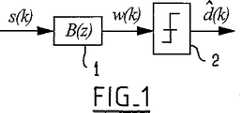
図1は、トランスバーサルフィルタの原理を示すブロック線図であり、図中、フィルタ1は伝達関数B(z) を有することが示されており、該フィルタ1より下流に配置された、2で示される判定回路を伴っている。
【0008】
その後にはじめて、平均2次誤り (mean quadratic error, MQE) の最小化を最適化判定基準として用いた適応等化器が出現した。難通信路 (difficult channel)では、ゼロ強制ISIは等化器からの出力雑音の非常な増大を生じて、性能のひどい劣化の原因となって終わるのに対し、MQEを最小化するという判定基準は、雑音を著しく増大させずにISIの顕著な減少を達成するという賢明なバランスを与える結果となった。
【0009】
一般的観点から、適応等化は従来より2段階で行われてきた。第1段階では、収束を保証するのに十分な長さのトレーニング系列を用いて装置を動作させ、次に第2段階では装置は自己適応性になる、即ち、装置自体の判定に基づいて自己制御するようになり、その戦略 (手法) に内在する全ての危険が付随する。
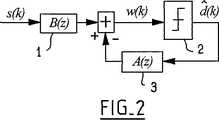
【0010】
より最近になって、図2に示すように、A(z) と書かれた伝達関数を有し、フィルタの巡回 (リカーシブ) プロトンを構成する帰還フィルタ3に判定データを再注入する、非線形の巡回式判定帰還型 (recursive decision feedback)等化器について、下記刊行物に提案がなされた:
[2] C.A. Belfiore, J.H. Park「判定帰還型等化」Proceedings of the IEEE 67(8), 1979年8月。
【0011】
この手法によって、線形等化器を用いて得られる性能より極めて明らかに優れた性能を達成することが可能になる。残念ながら、そのような装置は判定誤りにも極めて敏感となることがあるため、時に誤り伝搬現象が起こり、その程度が、装置の出力が伝送データに対して全く適切性を持たなくなるように装置を逸脱させてしまうまで進むことがある。
【0012】
従って、このような状況下では、装置を定期的に監督することが必要となるが、それにより少なくとも周波数利用効率の著しい低下が起こる。
換言すると、等化器の異常動作を防止するように、装置の挙動を定期的に (より良好には連続的に) 監視しなければならない。
【0013】
本発明の一般的な目的は、その問題を鮮やかに解決することができる技術を提案することである。
別の観点からは、判定帰還型等化器 (DFE) が、誤りの可能性を最小化するという判定基準 (最大事後判定基準に等しい) に関して最適ではないというのは本当であるが、下記に記載された最適受信機は、インパルス応答の長さが大きくなった時にはすぐに達成が不可能になるというのも、なおそのままである:
[3] G.D. Forney, Jr.「符号間干渉の存在下でのディジタル系列の最尤(ユウ)系列推定量」IEEE Trans. on Information Theory, Vol. IT-18n, pp. 6363-6378, 1972年5月。このような装置は、最初に伝送通信路のインパルス応答を推定した後、全ての可能な送信系列の中から、こうして推定された通信路から真に利用可能な (ベクトル) 観測に最も近い (ベクトル) 信号で出力されるらしい系列を探す。
【0014】
現在、このような受信機の実施には、下記に記載されるように、ビタビアルゴリズムが利用されている:
[4] G.D. Forney, Jr.「ビタビアルゴリズム」Proc. IEEE, Vol. 61, pp. 268-278, 1973年3月。その主な利点は、最適性を失わずに「進行中」に判定を下すことができることである。換言すると、シンボルの最も可能性の高い系列に関して判定を開始する前にメッセージを完全に受信する必要がない。
【0015】
しかし、1例として、離散インパルス応答が長さ15 (15Tのオーダーの時間広がり) の通信路で伝送された4位相状態で変調された信号について、このようなシステムに付随するトレリスは10億の可能な状態を有する。そのため、事実上、この種の受信機は、少なくともリアルタイム用途においては実際に不可能となる。海底音声通信路、電離層通信路、および電話線 (対より線) にあてはまるように、用途によっては、このような時間広がり (time spreading) はごく普通であり、これは、一般的見地からは、指定周波数帯内でのデータ率が著しく増大した場合、全ての伝送通信路にあてはまることがある。
【0016】
この種の通信路にはますます高いデータ率を搬送する試みが常になされていることは明らかであり、それによりインパルス応答の時間スパンは容赦なく長くなる。離散インパルス応答のサイズが大きくなった時に、判定帰還型等化器が最適受信機に代わる有利な代替品となるのは、この意味においてである。例えば、現在のGSM標準移動体無線通信では、時間広がりは6Tのオーダーであり、これは二元 (binary) 変調では64の状態を意味し、従って、最適受信法の使用に非常に適している。インライン・データ率の増大という当然の理由のために四元変調に変化すべきことになった場合、および変調速度を倍増させることも望ましくなった場合、状態の数は1千7百万のオーダーとなり、これは明らかに重すぎる。これが、なぜ判定帰還型等化器 (DFE) が、理論的には次善であっても、複雑さと性能とのバランスに関して明らかに大きな利点があるという理由であり、異常原因となる可能性がある性能を管理下に保持できるからである。
【0017】
上に述べたように、難通信路で従来より使用されてきた方法は、必要に応じてDFEをリセットする状態となるように定期的にトレーニング系列を送信することからなる。これは、それによりひどく影響を受けることがある周波数利用効率に有害である。これが、ブラインド (blind)等化 (自己学習型、監督なし) に対して多量の研究が現在行われている背景にある基本的な理由である。その目的は、トレーニング系列を使用せずに装置をその最適解答に収束させる、即ち、ソースから送信された信号に関する統計学的知識だけに基づいて特異的にそうすること、である。
【0018】
この主題については、これまでに下記を含む何名かの研究者が無視できない報告をしている:
[5] Y. Sato 「多段振幅変調のための自己再生等化法」IEEE Trans. on Com., COM-23, pp. 679-682, 1975年6月;
[6] D.N. Godard 「二次元データ通信システムにおける自己再生等化および搬送波トラッキング」IEEE Trans. on Com., COM-28, pp. 1867-1875, 1980年11月; [7] A. Benveniste, M. Goursat 「ブラインド等化器」IEEE Trans. on Com., Vol. 32, 1984, pp. 871-883;
[8] O. Shalvi & E. Weinstein「非最小位相システム (通信路) のブラインド・デコンボリューションのための新規判定基準」IEEE Trans. on IT, Vol. 36, No. 2, 1990年3月, pp. 312-321;
[9] C.A.F. Da Rocha, O. Macchi and J.M.T. Romano「自己学習等化用の適応非線形IIRフィルタ」ITC 94, ブラジル, リオデジャネイロ, pp. 6-10, 1994;
[10] B. Porat, B. Friedlander 「高次モーメントを用いたディジタル通信チャネルのブラインド等化」Trans. on SP, Vol. 39, pp. 522-526, 1991年2月;
[11] V. Shtrom & H. Fan 「ブラインド等化における新規種類のゼロ強制費用関数」IEEE Trans. on SP, Vol. 46, No. 10, 1998年10月, pp. 2674-2683。
【0019】
それらのアルゴリズムの全てが、2より高次の (3次以上の) 統計処理に暗に言及している。これは、最小位相通信路を反転させるためにそのようなモーメントを使用する必要があることに付随する。その種の最初の等化器は一般に線形でトランスバーサル、即ち、有限のインパルス応答を持つものであった。
【0020】
ごく最近になって、鮮やかで特に効果的な解決策が、Labat らにより下記刊行物中に提唱された:
[12] J. Labat, C. Laot & O. Macchi「ディジタル通信システム用の適応等化器装置」フランス特許No. 95/10832;
[13] J. Labat, O. Macchi & C. Laot「判定帰還型適応等化: トレーニング期間をスキップできるか?」IEEE Trans. on COM, Vol. 46, No. 7, pp. 921-930, 1998年7月。
【0021】
以下に簡単に説明する、その新時代の等化器は、伝送通信路の過酷度 (severity) に適応した2つの動作モード (mode of operation)を有する。「収束 (convergence)」モードと呼ばれる初期モードでは、図3に示すように、装置は、純リカーシブ(purely recursive)白色化フィルタ4、トランスバーサルフィルタ5、自動利得制御 (AGC) 6、および位相修正器7のカスケード (縦続) 接続により構成される。この装置の独創性は、各段階を特定の判定基準を用いて適応させることにより、収束に対しエラー強さ (誤りへの適応能力) とスピードの両者を付与した点に付随する。等化プロセスが十分に進展したなら (これは、受信機が取得した判定に基づいて推定された平均2次誤り (mean quadratic error, MQE) を検査することにより評価できる) 、等化器を適応させるための構造および判定基準を、装置が従来型の判定帰還型等化器 (DFE) になるように変更する (図4) 。この変更の可逆的性質により、従来のDFEとは違って逸脱の危険性を伴わずに、可能な時にはいつでもそれ自体の判定を利用するという実質的な利点が、上記の新規等化器に与えられる。伝送条件が突然変化した場合には、この新規等化器はその初期形態に戻り、こうして等化器を新たな状況に再適応させることができる。このような条件下では、この新規等化器はこれがより良い性能を達成することができる形態を常に選択することができることから、線形装置とDFE型等化器との間の選択の問題は全く起こらない。
【0022】
【発明の要約】
本発明の目的は、特に良好な性能を与えるマルチチャネル等化器、特に時空等化器 (即ち、複数の並列センサにより同時に捕えられた信号を利用することができる等化器) を提案することである。
【0023】
この目的のために、本発明は、複数の受信通信路 (受信チャネル) を有するディジタル通信システム用の等化器(イコライザ)装置を提案する。この装置は、正規動作 (normal operation) では、各受信通信路に対してトランスバーサルフィルタを形成する手段、該複数の通信路を加算する加算手段、および位相修正手段と、その前方枝路に判定手段を備えたむ純リカーシブフィルタとを備えた、該加算手段より下流のシステムを含む構造を与え、前記等化器装置は、その性能を該装置からの出力信号の関数として評価し、かつトラッキングモードもしくは易受信モードとも呼ばれる正規動作モードに対応する構造から、難受信モードとも呼ばれる収束動作モードに対応する構造への、またはその逆への切り換えによって前記評価の結果に応答するための判定取得手段を備えている。本発明の等化器装置は、収束および/または難受信モードにおいて、各受信通信路ごとに1つの純リカーシブフィルタを備える構造を与え、この純リカーシブフィルタが前記加算手段より下流のシステムには存在しないことを特徴とする。
【0024】
かかる装置は、下記の各種の特徴を、単独または任意の技術的に可能な組合わせで伴うことが有利である:
・装置が正規モードと収束または難受信モードのいずれで動作中であるかに応じて、装置のトランスバーサル部分およびリカーシブ部分を更新するための装置の判定基準を変更する手段を備える;
・収束または難受信モードにおいて、リカーシブフィルタは2次の判定基準を用いて更新され、トランスバーサルフィルタは2より大きな次数 (3次以上) の統計学的判定基準を用いて更新される;
トラッキングまたは易受信モードにおいて、推定平均2次誤りを最小化するように装置を制御する手段を備える;
・装置の性能レベルを平均2次誤りの推定値の関数として決定する;
・収束モードにおいて、位相修正手段が判定取得手段にすぐ隣接して配置される;
・装置が自動利得制御手段を備える;
・トラッキングまたは易受信モードにおいて、自動利得制御手段がトランスバーサルフィルタを構成する手段により構成される;および
・収束モードにおいて、自動利得制御手段がリカーシブフィルタより上流に位置する。
【0025】
本発明また、受信データが複数の通信路にわたって分数的に離間される分数離間型 (fractionally-spaced)の等化器装置であって、上記種類の装置により構成されることを特徴とする装置も提供する。
【0026】
本発明はまた、連続流データ伝送システムまたはパケット伝送システムであって、上記種類の等化器装置を備えることを特徴とするシステムも提供する。
このような時空等化器は、判定帰還型の多様な形態の自己学習を行う。推定平均2次誤り、または等化器からの出力信号の尖度 (とがり) 、またはより一般的には任意の関連する費用関数 (Godard [6], Shalvi & Weinstein [8], Shtrom & Fan [11], ...) といった、インライン (ライン内) で発生した信号の関数として、等化器はその構造および最適化判定基準に関して「最適」となるようにその構造を自分で形作る。「収束」モードと呼ばれる、その初期の動作モードでは、装置は線形でリカーシブ (巡回型) であるのに対し、「トラッキング」モードと呼ばれる、その正規動作モードでは、装置はそれ自体の判定によって制御される従来の時空DFEになる。それら2つの形態の一方から他方への切り換えは完全に可逆的であり、これは安定しない (定常的ではない) 通信路では特に魅力的である。その結果、本発明により提案された装置では、収束とトラッキングの両方に関して最も有利な性能を達成することが可能となる。この不可欠な特性により、従来技術の慣用の等化器とは異なり、過酷な状況での通信路の変動に適応させることが可能となる。この観点から、本発明により提案された装置は、移動体無線通信路、電離層通信路、対流圏通信路、および海底音声通信路といった、安定しない通信路に特に適応する。
【0027】
本発明の他の特徴および利点は、下記の説明からさらに明らかとなる。この説明は純粋に例示であり、制限するものではない。以下の説明は添付図面を参照しながら読むべきである。
【0028】
【発明の態様の説明】
一般説明
本発明により提案されたマルチチャネル等化器装置は、これが収束モード (モード1) であるか、またはトラッキングモード (モード2) 、即ち、正規動作条件下であるか、に応じて2つの異なる構造を与える。これらの2つの構造は図5および6に示してある。
【0029】
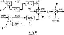
収束モード時に使用する構造 (図5) では、この時空等化器が使用するP個の受信通信路のそれぞれにおいて、1個の純リカーシブフィルタ8がトランスバーサルフィルタ9に先行する。さらに下流側では、加算回路10の後に、AGC (自動利得制御) 11および位相修正12の両方が存在すべきである。これらの要素の全てが「ブラインド (blind)」判定基準、即ち、その統計学的特性に関する事前知識以外には、伝送データに関する知識を全く必要としない判定基準、に基づいて適応される。
【0030】
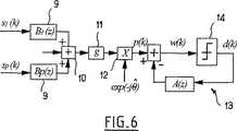
トラッキングモードでは、装置が慣用の時空DFEの形になるように、トランスバーサルフィルタとリカーシブフィルタの位置が変更される (図6) 。それにより、全体の最適化判定基準は平均2次誤り (MQE) の推定値を最小化するという判定基準になる。この動作モードでは、AGCは一般に禁制される、即ち、構造を変化させる前にそれが示していた値に固定される。このように構造を変化させる時、最適化判定基準も並行して変化させる。通信路の過酷度に応じて、かつ2次誤り、尖度 (累積、4次) 、出力信号w(k) 、または他の何らかのインライン推定費用関数 (Godard [6], Shalvi & Weinstein [8], Shtrom & Fan [11], ...) といった、装置の性能を測定するためのインラインで発生した信号を使用して、図5に示したような線形の自己学習型リカーシブ (巡回型) 構造から、図6に示したような非線形の時空DFE構造に、または逆に判定制御DFE型構造から線形の自己学習型リカーシブ構造に、装置が切り替わる。対応する構造を、収束モードとトラッキングモードの両方に関して以下に説明する。
【0031】
当然、収束モードでは、装置は線形であるので、時空DFEを構成する各種要素の位置は変更することができる。この変更は、システム内でいくつかの位置に配置できるAGCに特に関係し、AGCは恐らく省略することも可能であり (g=1 にセットすることになる) 、その場合にはトランスバーサルフィルタがAGC機能も引き受ける。こうして、制限ではないが例示の様式では、AGCは位相修正器のすぐ上流または下流に、さらには純リカーシブフィルタの上流または下流に位置させることができる。純粋に理論的な観点からは、キャリヤ (搬送波) 再生機能を果たす位相修正器はシステムのどの位置に配置することも可能であるが、その理想的は位置は判定回路のすぐ隣りであることは明らかである。これは、適応に一般に用いられる判定基準、即ち、推定平均2次誤りを最小化するという判定基準に伴うものである。但し、本技術分野で利用可能な技術を使用した他のよりエラー強さのある技術も使用できよう。
【0032】
(1) モード1:収束モードおよび/または受信が困難な期間
図5に示す収束形態に対応する構造は、P個のアンテナセンサに対応するP個の受信通信路を有し、各通信路は、伝達関数 1/[1+A(z)] の同一の純リカーシブフィルタ8と、i = 1, 2, ..., Pについてそれぞれ伝達関数Bi(z) のトランスバーサルフィルタ9を備える。この構造はさらに、加算回路10、自動利得制御装置 (AGC) 11、および位相修正器12を有する。
【0033】
まず、AGCと位相修正器 (キャリヤ再生) のそれぞれの位置は、少なくとも非適応戦略においては、理論的に重要ではない。即ち、AGC (gで特徴づけられる) は、純リカーシブフィルタの上流もしくは下流に、さらには位相修正装置の上流もしくは下流に配置することができ、またはこれを省略することもできる。1つの適当な位置は、図5に示した位置である。
【0034】
2次判定基準 (quadratic criterion)のリカーシブフィルタおよび単一判定基準 (single criterion) のトランスバーサルフィルタが2より大きな次数 (3次以上) の統計処理を含むため、AGC装置11の利得gはブラインド判定基準を用いて更新される。トランスバーサルフィルタの係数を更新するには、いくつかのアルゴリズム、特にGodard [6], Shalvi & Weinstein [8], Shtrom & Fan [11],等のもの、を使用することができる。
【0035】
搬送波または修正用位相の再生、即ち、位相誤りの推定と、
【0036】
【数1】
での複素乗算によるその補償は、例えば、推定平均2次誤りを最小化するという判定基準を用いて行われる。得られた誤り信号を次に、2次装置 (または必要なら2より大きな次数の装置) に後退するようにフィルタにかけることができる。この装置もまた、システムの線形性のためにシステムの多様な位置に配置することができる。但し、実際には、少なくとも考慮する判定基準のために、これを等化器より下流に配置するのが賢明なようである。この収束モードでは、位相修正は、送信された信号配座 (signal constellation) の対称性を利用した判定によって (よりエラー強さの大きい他の判定基準を用いて構想することも可能ではあるが) 制御することができる。いずれにしても、残りの他の関数は、適当な装置 (閾値回路) が取得した判定には全く依存しない判定基準に基づいて最適化される。従って、この第1工程は完全に自己学習型 (ブラインド型、非監督型) である。また、その構成装置のそれぞれは適当な最適化判定基準を有し、それにより装置全体に対して非常にエラー強い性質を付与する。
【0038】
(2) モード2:トラッキングモードおよび/または受信が容易な期間
推定MQE、尖度または任意の他の費用関数 (Godard [6], Shalvi & Weinstein [8], Shtrom & Fan [11], ...) の観察により推論することができるように、通信路がほぼ等化されたなら、伝達関数 1/[1+A(z)] を有する複数の線形の純リカーシブフィルタ8を、図6に示すように異なる位置に配置された、同じ伝達関数を有する1つのフィルタ13に交替させ、このフィルタには今度は、14で示される装置の判定回路により取得された判定
【0039】
【数2】
が供給される。当然、この機能を実行するには、収束モード1において、時空DFEのP個の通信路の全てについて同一のリカーシブフィルタを有する必要がある。得られた新たな構造は、推定平均2次誤りを最小化するという判定基準を用いた判定により制御される従来の時空DFEの構造である。また、判定されたデータ項目の尤度 (見込み) が低いと判断される場合には、判定されたデータ項目
【0041】
【数3】
の代わりに、判定回路14の入力部の信号w(k) をフィルタA(z) に再注入して、これと取り替えるように選択することも可能である。
リカーシブフィルタA(z) に雑音の多いデータw(k) を注入する方が、尤度の低い (従って、間違っている可能性の高い) 判定データ
【0043】
【数4】
をそれに注入する危険をとるより、一時的には良好であると考えられる。この進行方式は、トラッキングモードにおける装置のエラー強さを高めることができ、この点において、これは時空DFEの可能性を秘めた改善となる。さらに、このトラッキングモードにおいて、AGCは、gをその先行値に固定することによりトランスバーサルフィルタBi(z) において積分することができる。
【0045】
こうして、この時空等化器は、異なる構造および最適化判定基準に伴う2つの異なる動作モードを与えることが理解されよう。
この新規な装置の本質的な特徴の1つは、この構造変更が完全に可逆的であることである。このような特性は有利であり、過酷な条件下では収束モード、即ち、非常にエラー強い動作モードに戻すことができる。一方、通信路の過酷度が小さくなると、これは付随する平均2次誤りの減少を生じ、システムは、トラッキングモード、即ち、判定帰還型構造の等化器に戻るように切り換わり、以後も同様である。この点において、この装置は独創的で特に魅力的な特徴を与える。
【0046】
この構造の切り換えと並行して、トランスバーサル部分とリカーシブ部分の係数を更新するのに用いる判定基準を変化させる。モード1では、これらの判定基準は、ソースにより伝送された信号の統計処理に関する事前知識だけに依存するのに対し、トラッキングモードでは、最適化判定基準は推定MQEを最小化するという判定基準である。
【0047】
態様の詳細な説明
本発明の時空等化器装置の1態様に関して以下に詳細に説明する。
(1) 収束モードおよび/または難受信期間
1.1- 演算式
装置の動作を支配する演算式は、下記の通りである: i = 1, 2, ..., P について、次式が適用される:
【0048】
【数5】
ここで、si(k) は時間kにおける通信路iの入力時の信号を意味し、ui(k) は通信路iのフィルタ8による出力信号を意味し、ここで:
【0050】
【数6】
である。下記もまた適用される:
【0052】
【数7】
ここで、vi(k) は通信路iのトランスバーサルフィルタ9からの出力信号を意味し、ここで:
【0054】
【数8】
であり、下記も適用される。
【0056】
【数9】
1例として、ベクトル Biは、Bi(0)=[0,0,...,1/P,0,0]Tにより初期化することができ、C(0)はN次元のゼロベクトルである。
1.2- 収束モードにおけるパラメータ更新
1.2.1- 純リカーシブフィルタ
リカーシブフィルタを適応させるのに使われる最適化判定基準は、下記の費用関数を最小化することである:
【0058】
【数10】
これは、回帰的最小二乗型または「確率勾配 (stochastic gradient)」型のアルゴリズム法を用いて行うことができる。下記で与えられる更新演算式は、確率勾配アルゴリズムから得られる:
【0060】
【数11】
ここで、μaは適当な適応段 (adaptation step)である。
1.2.3- トランスバーサルフィルタ
信号v(k) は、より簡潔には下記のように書くことができる:
【0062】
【数12】
但し、
【0064】
【数13】
更新に用いる判定基準は、これ以外も可能であるが、Godard [6]のもの、Shalvi & Weinstein [8]のもの、またはShtrom & Fan [11] のものである。純粋に表示のためであるが、Godardにより規定された費用関数は下記の通りであることを想起されたい:
【0066】
【数14】
実際には、パラメータpは2に等しいと選択されるが、他の値も可能である。
Shalvi & Weinsteinにより提案された判定基準は次の通りである:
【0068】
【数15】
ShtromおよびFan は、トランスバーサルフィルタの更新にも使用することができる、[11]に十分に説明されている多様な費用関数を提案した。一般に、これらの判定基準に由来するアルゴリズムは、少なくともそれらの確率勾配バージョンにおいては、参考文献として引用した論文に説明されている。純粋に例示の目的として、p=2 に対するGodardのアルゴリズムに由来する更新の関係式は、i = 1, 2, ...,P に対して、次の通りであることを想起されたい:
【0070】
【数16】
ここで、μbは適当な適応段である。
既述のように、純粋に表示として、基準係数 (reference coefficient)はフィルタ Biのそれぞれについて1/P に等しいと選択することができ、その位置は自由にされる。実際には、等化器のペイバック(payback) 遅延を決める、これらの係数の位置は、これらのフィルタがいくらか抗因果的 (anticausal) となる傾向があるように選択される。
【0072】
1.2.4- 位相修正
1つの可能な判定基準は、推定MQEを最小化すること (判定されたデータに基づいて) である。明らかに、この判定基準はその後、判定により制御されることになるので、エラー強さが小さい。これが、なぜこの装置を、上流段階の混乱を避けるようにシステムの下流端に配置するかという理由である。そうなると、費用関数は次のように表される:
【0073】
【数17】
これから派生する更新アルゴリズムは次の通りである:
【0075】
【数18】
但し、
【0077】
【数19】
は適当な適応段である。
1.2.5- 自動利得制御
自動利得制御装置は必須ではないが、場合によってはこれを設けることが有利となりうる。この場合も、構造の線形性を考慮して、この装置の位置を自由に選択することができる。1つの適当な位置は図5に示した位置である。この場合、利得gを更新するための1つの可能なアルゴリズムは下記の更新式に対応し:
【0079】
【数20】
但し、G(0) = 1であり、μgは適当な適応段であり、一方
【0081】
【数21】
はソースにより送信されたデータの分散 (variance) を意味する。
安定性に関して有利でもある別の解決策は、gで特徴づけられるAGCを、伝達関数 1/[1+A(z)] を有する純リカーシブフィルタより上流に配置することである。その時、利得gを更新するための1つの可能なアルゴリズムは下記の更新式に対応する:
【0083】
【数22】
(2) 切り換え規則
どの動作モード (収束またはトラッキング) を使用すべきか決めるため、等化器の性能を評価する信号をインラインで発生させる。こうするために、例えば、推定MQEのMDD(k)を、下記アルゴリズムを用いて:
【0085】
【数23】
または、同じ原理で作成された任意の他の費用関数、例えば、この概念を例示するために、次式のように推定されたGodardの関数[6] を用いて、決めることができる:
【0087】
【数24】
ここで、λは忘却因子 (forgetting factor)を意味する。
推定MQEを制御信号として使用する場合、下記アルゴリズムを実行することにより形態 (動作モード) が選択される:
【0089】
【数25】
換言すると、推定MQEのMDD(k)が閾値 M0より大きい場合には、等化器は収束モードとなり、これが閾値 M0より小さい場合には等化器はトラッキングモードとなる。
【0091】
このような状況下では、推定MQEは真のMQEに非常に近くなることがわかる。DFEモードへの安全な移行を確実にするため、閾値は十分に小さく選択しなければならない。また、一般に、MQEが減少すると、誤りの可能性も減少する。従って、等化器の異常原因となる挙動を避けるように、典型的には0.02程度の十分に小さい二元誤り率(binary error rate, BER) に対応する閾値を決めるのが適当である。その収束モードで等化器がゼロ強制型のものであると仮定すると、BERはMQEの関数として表すことができる。こうすると、4準位直交振幅変調 (4-QAM) では、このような定数は閾値 M0=0.25 (−6 dB) を選択することになる。このような状況下では、推定MQEは一般に真のMQEに近いので、この点で推定MQEは、等化器が使用する動作モードを制御するための性能の良好な指数となる。
【0092】
(3) トラッキングモードおよび/または易受信期間
この動作モードは、推定MQEのようなインラインで発生した信号が、使用した変調に調和した閾値 (例、4相ディジタル位相変調 <QPSK> では0.25) と交差した時に始まる。このような状況下で、トランスバーサルフィルタとリカーシブフィルタの位置が、従来の時空DFEとなるように入れ替わる。換言すると、等化器は、コンテクストの過酷度の関数として、線形のリカーシブ構造から非線形のリカーシブ構造へ、またはその逆に切り替わる。そうなった時、この動作モードでは、判定基準は一意的、即ち、推定MQEを最小化することである。この判定基準を用いて、回帰的最小二乗型または確率勾配型のアルゴリズムあるいは現状技術における他の任意の対応するアルゴリズムを用いて、等化器のパラメータの全てを更新する。gで特徴づけられる自動利得制御は、一般にはその以前の値に固定され、その後、この機能は自動的に各トランスバーサルフィルタにより実行される。一方、位相修正器は動作し続けるが、その位置は同様に、図6の図に示したように変更することができる。
【0093】
3.1- 演算式
この動作モードを支配する演算式は次の通りである:
【0094】
【数26】
但し、
【0096】
【数27】
および
【0098】
【数28】
但し、
【0100】
【数29】
3.2- トラッキングモードにおけるパラメータ更新
3.2.1- トランスバーサルフィルタ
そうなると、時空等化器のフィルタBi(z) を更新するための式は次のようになる:
【0102】
【数30】
3.2.2- リカーシブフィルタ
【0104】
【数31】
3.2.3- 位相修正器
更新アルゴリズムは、適当な適応段μgで、次の通りである:
【0106】
【数32】
特殊な場合
2相ディジタル位相変調 (BPSK) では、最適2次判定基準は下記の費用関数を最小化することであるのを認めることは重要である:
【0108】
【数33】
その後、そこから派生した式を、特に困難を伴わずに、直接演繹することができる。BPSKでは、この判定基準の方が2次判定基準より適切である。また、収束モードでは、リカーシブフィルタのベクトルAを適応させるための適切な判定基準は、このベクトルの係数を実数に制約するという条件下で、下記の費用関数を最小化することである:
【0110】
【数34】
それから派生する式を直接得ることができる。残りの判定基準は、MQEbpskを最小化する位相修正に関するものを除いて、全ての点で前述した判定基準と同様である。
【0112】
本発明の可能な別の態様を構成する自己学習型の時空DFEの両方の動作モードは上に説明されている。上述した更新の実行は、確率勾配アルゴリズムから得られる。もちろん、これらを最小二乗型もしくは高速 (fast) 最小二乗型の方法、または現状技術に対応する他の任意の方法を用いて得ることもできよう。
【0113】
通信路が劣化した状況になると、装置は自動的に収束モードの形態になるので、この装置が達成する性能レベルは顕著である。一方、通信路がよくなると (これはインライン信号から検出される) 、この装置はトラッキングモードの形態になり、その後も同様である。
【0114】
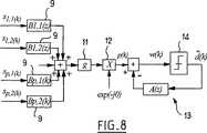
最後に、本発明の主題をなす上述した等化器の原理は、分数離間型の等化器、即ち、Tより小さい単位時間間隔 (例、T/2)で時間が離間しているサンプルを使用する等化器、に拡張することができる。
【0115】
このような等化器は図7および8の図により十分に開示されている。この目的のため、非常に普及しているやり方に対応する、2/T のレートでとったサンプルを使用する分数離間等化器について考察すると、信号 si,j(k) は次のように定義される:
s1,1(k) = s1[kT]
s1,2(k) = s1[kT-T/2]
sp,1(k) = sp[kT]
sp,2(k) = sp[kT-T/2]
図7および8に現れる残りの信号に関し、表記法は上記と同じ原理に基づく。
【0116】
トラッキングモードでは、更新用の式は現状技術に対応する慣用の分数離間型DFEのものである。収束モードでは、中間サンプル sn,2(k) = sn[kT-T/2]を別のセンサから来るとして考慮することで十分であり、そうすると前述した式がこの新たな装置に十分に当てはまり、一般的観点からは、2Pセンサを有する時空DFEを構成すると考えることができる。
【0117】
応用
上述した装置は、連続流のデータで動作または演算する通信システムおよびパケット方式 (ブロック、バースト) で動作または演算する伝送システムにそのまま適用できる。パケット伝送方式では、この装置は、必要なだけ頻繁にブロック等化プロセスを反復するので十分である。その場合、基本概念は非常に単純である。第1回のパスが問題のブロック (パケット) 上で行われる。かかる条件下では、このパスの最後に推定された (等化器) パラメータはそれらの最終値により近くなる。その結果、その後の反復パス (iteration)は、前回の反復パスの最後に推定された値に対して装置のパラメータを初期化することにより行われ、以後も同様である。ある数のパス、典型的には4または5回、を行うことにより、最も例外的な結果が得られる。この動作方法によりパケット方式伝送システムに使用することが可能となり、例えば、BPSKでは、この「ブラインド」戦略に必要な最小ブロックサイズは約150 シンボルであり、これは非常に有利で、現在の標準規格で規定さている要件と合致する。この手順は、多くの今日のシステムが時分割多元接続 (TDMA) を利用していることから、応用にとって非常に有利である。
【0118】
本発明がカバーする分野は、これ以外にもあるが、マイクロ波電気通信、移動体無線、対流圏および電離層無線、ならびに海底音声通信である。これらの難通信路は全て、非常に不安定という特別の特性を示し、一般に、シンボル時間Tに比べて長いインパルス応答を有するため、G.D. Forney [3] が報告した種類の最適受信器を使用することが事実上は不可能となる。また、電話機や電話ケーブルも本発明の装置が関係することがあり、P=1 (1センサだけ) に設定し、分数離間戦略を選択するので十分であり:このような状況下では、この装置は2センサの時空DFEであると考えることができる。対より線による「高データ率」伝送 (XDSL, HDSL, VDSL等、ここでDSLは「ディジタル加入者線」を表す) に対する現在の提案は、この新規装置に対する可能な用途を構成する。
【0119】
本発明が関係する変調の種類は、全て線形型の変調であり、特に振幅変調 (パルス振幅変調) 、直交する2つの搬送波の振幅変調 (QAM) 、位相変調 (MPSK) 、およびある種の周波数変調 (ガウス型最小偏位変調 <GMSK> 等) である。全体的にみて、この新規な装置は、現在使われているほぼ全ての種類の変調に適応させることができる。
【0120】
この新規な等化器は、既に海底音声通信信号について成功裏に試験された。結果は、パケット方式での伝送を含めて、非常にうなずけるものである。現在の科学界では、ブラインド処理は、有望ではあるが、パケット方式での伝送への現在の応用からみて許容されない収束時間になる技術であると、不当に考察されることが多い。実際は、本発明の時空等化器により、適度のサイズのブロックについて最も有利な性能を得ることが可能になる。これらの点を海底音声通信に関して例示するため、我々は、莫大である、60T近くにひろがるインパルス応答の時間スパンで、25 kbit/s のデータ率の4相ディジタル位相変調 (QPSK) 信号における1000シンボルのブロックを成功裏に処理した。このような結果が、特に交換する情報量が小さい時もある海底音声通信の分野で、ある種のプラクティスを変化させることになるのは疑いない。このような用途では、現在実施されている技術は、パケット方式伝送を使用する時に、コヒーレント受信技術、即ち、より高性能の技術を構想することが完全に可能であっても、非コヒーレント受信機を一般に利用している。もちろん、パケットの持続時間は、伝送通信路がこの範囲内で安定していると考えることができるように選択しなければならない。
【0121】
適用の1例
本発明の新規装置の性能を例示するため、従来のエントレインド (entrained)型の時空等化器と上述した種類の時空等化器とを使用して、海底音声通信で得られた各種の結果で比較を行う。使用した変調はQPSK型のものであり、搬送波周波数は62 kHz、ビット伝送速度は33 kbit/s であった。伝送通信路の離散インパルス応答の時間スパンは約60Tであり、従って、最尤 (最大の尤度) の点で最適の受信技術は全くありえないことになる。
【0122】
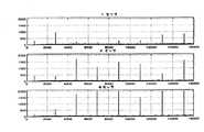
この位相時間等化器を用いて、同期型および分数離間型の方策を、エントレインド方式と「ブラインド」方式の両方において十分に検討した。トレーニング系列のシンボル数は1000であった。いくつかのグラフは、特に推定MQEの値が判定されたデータに基づいてどのように変動したかを示す。並行して、各形態について、1、2または4個のセンサを使用した場合に、判定されたデータ
【0123】
【数35】
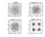
を、送信系列 (2047シンボルからなる最大長の白色系列) に適応させた相関器を通過させることによって得られた信号を示す。最後に第3の種類のグラフは、等化器が1、2または4個のセンサを備える場合の、等化器の入力および出力配座を示す。
【0125】
結果は図9〜20に示す。これらの図から、同期型と分数離間型のいずれであろうと、「ブラインド」方策の方がエントレインド方策より非常に優れていることがわかる。
【0126】
センサ4個の分数離間型 (図16) においてすら、エントレインド方式の時空等化器は結果を生ずることができない。これに対して、1個のセンサを用いた場合で、分数離間型の「ブラインド」等化器からの出力は、相関器からの出力にピークが存在する (それらのピークは送信されたメッセージの認識を反映している) ことからわかるように、何らかの適切さを示している (図19) 。
【0127】
この傾向は、2個のセンサを用いた場合にはかなり強くなり、4個のセンサを用いた場合には、さらに一層はっきり確認される。
こうして、実際のデータファイルを用いたこれらのいくつかの結果に基づいて、本発明の時空DFEは、最も過酷な伝送通信路について最も有利な性能を与える革新的な技術であることがわかる。
【図面の簡単な説明】
【図1】 線形トランスバーサル時間等化器のブロック線図である。
【図2】 判定帰還型の時間等化器のブロック線図である。
【図3】 既に提案された時間等化器[12]の収束モードでの構造を示す図である。
【図4】 同じ時間等化器のトラッキングモードでの構造を示す図である。
【図5】 本発明の可能な態様に従った時空等化器の収束モード構造を示す図である。
【図6】 本発明の可能な態様に従った時空等化器のトラッキングモード構造を示す図である。
【図7】 本発明の可能な態様に従った分数離間型の時空等化器の収束モード構造を示す図である。
【図8】 本発明の可能な態様に従った分数離間型の時空等化器の収束モード構造を示す図である。
【図9】 1、2および4受信通信路について同期型エントレインド式の判定帰還型等化器に対する平均2次誤りの曲線をプロットしたグラフである。
【図10】 同じく相関器からの出力をプロットしたグラフである。
【図11】 同じく入力および出力配座をプロットしたグラフである。
【図12】 1、2および4受信通信路について同期型自己学習式の判定帰還型等化器に対する平均2次誤りの曲線をプロットしたグラフである。
【図13】 同じく相関器からの出力をプロットしたグラフである。
【図14】 同じく入力および出力配座をプロットしたグラフである。
【図15】 1、2および4受信通信路について分数離間型エントレインド式の判定帰還型等化器に対する平均2次誤りの曲線をプロットしたグラフである。
【図16】 同じく相関器からの出力をプロットしたグラフである。
【図17】 同じく入力および出力配座をプロットしたグラフである。
【図18】 1、2および4受信通信路について分数離間型自己学習式の判定帰還型等化器に対する平均2次誤りの曲線をプロットしたグラフである。
【図19】 同じく相関器からの出力をプロットしたグラフである。
【図20】 同じく入力および出力配座をプロットしたグラフである。[0001]
DESCRIPTION OF THE GENERAL FIELDS AND PRIOR ART
The present invention relates to an equalizer device (or “equalizer”) for a receiver of a multi-channel digital communication system.
[0002]
In current communication systems, receivers have a variety of functions including demodulation, shift from received signal to baseband, equalization, synchronization (clock frequency and carrier), decision making, and channel decoding (decoding). Fulfills the function.
[0003]
Equalization is essentially reducing intersymbol interference (ISI), a phenomenon associated with the communication system not meeting the so-called “Nyquist” criteria overall in its time domain version. Intersymbol interference can occur as a result of insufficient filtering strategies, insufficient selection of sampling instants, or multipath propagation phenomena. This is especially true for mobile radio channels, ionosphere or troposphere channels, and submarine voice channels.
[0004]
As a reference, the communication system can model discrete symbols with values taken from a finite size alphabet and transmit them on an equivalent discrete channel at a rate of 1 / T. Is recalled. This rate is called the modulation rate and is expressed in baud. Here, T means the time interval between the transmission of two subsequent symbols.
[0005]
Historically, the first device to combat the ISI phenomenon was introduced by Lucky in the following publication:
[1] R.W. Lucky “Automated Digital Communication Equalization” BSTJ 44, pp. 547-588. April 1965.
[0006]
The device includes a linear transversal filter that is essentially “synchronous” (uses one sample per symbol duration) and is adaptable if adaptation is required due to changes in the transmission channel over time. It is. The filter coefficients were updated using a criterion (called zero forcing zero) that minimizes noise by constraining zero ISI. This technique resulted in an “equalized” folded spectrum, so the term was used.
[0007]
FIG. 1 is a block diagram showing the principle of a transversal filter, in which the
[0008]
For the first time, an adaptive equalizer using the minimization of mean quadratic error (MQE) as an optimization criterion appeared. In a difficult channel, zero-forced ISI causes a significant increase in output noise from the equalizer, resulting in severe performance degradation, but a criterion for minimizing MQE. Resulted in a sensible balance of achieving a significant reduction in ISI without significantly increasing noise.
[0009]
From a general point of view, adaptive equalization has been performed in two stages. In the first stage, the device is operated with a training sequence long enough to guarantee convergence, and then in the second stage the device becomes self-adaptive, i.e. self-based on the device's own judgment. It comes to control and comes with all the dangers inherent in its strategy.
[0010]
More recently, as shown in FIG. 2, a nonlinear function has a transfer function written as A (z) and reinjects decision data into the
[2] C.A. Belfiore, J.H. Park “Decision Feedback Equalization” Proceedings of the IEEE 67 (8), August 1979.
[0011]
This approach makes it possible to achieve performance that is significantly better than that obtained using a linear equalizer. Unfortunately, such devices can be very sensitive to decision errors, so sometimes error propagation occurs, and the degree of the device is such that the output of the device is no longer suitable for the transmitted data. You may proceed until you deviate from.
[0012]
Therefore, under such circumstances, it is necessary to periodically supervise the apparatus, but this causes at least a significant reduction in frequency utilization efficiency.
In other words, the behavior of the device must be monitored regularly (better continuously) to prevent abnormal operation of the equalizer.
[0013]
The general object of the present invention is to propose a technique that can solve the problem vividly.
From another point of view, it is true that the decision feedback equalizer (DFE) is not optimal with respect to the criterion of minimizing the possibility of error (equal to the maximum a posteriori criterion). The optimal receiver described is still that it cannot be achieved as soon as the impulse response length is increased:
[3] GD Forney, Jr. "Maximum likelihood (Yu) sequence estimator of digital sequences in the presence of intersymbol interference" IEEE Trans. On Information Theory, Vol. IT-18n, pp. 6363-6378, 1972 May. Such a device first estimates the impulse response of the transmission channel, then, among all possible transmission sequences, is closest to the (vector) observation that is truly available from the channel thus estimated (vector). ) Look for sequences that appear to be output as signals.
[0014]
Currently, a Viterbi algorithm is used to implement such a receiver, as described below:
[4] G.D. Forney, Jr. “Viterbi Algorithm” Proc. IEEE, Vol. 61, pp. 268-278, March 1973. Its main advantage is that decisions can be made “in progress” without loss of optimality. In other words, it is not necessary to completely receive the message before initiating a determination on the most likely sequence of symbols.
[0015]
However, as an example, for a four-phase modulated signal with a discrete impulse response transmitted over a channel of length 15 (time spread on the order of 15T), there are 1 billion trellises associated with such a system. Have a possible state. This effectively makes this kind of receiver practically impossible, at least in real-time applications. Depending on the application, such time spreading is quite common, as is true for submarine voice channels, ionosphere channels, and telephone lines (paired strands), which, from a general standpoint, If the data rate within the specified frequency band increases significantly, it may apply to all transmission channels.
[0016]
It is clear that there are always attempts to carry higher and higher data rates on this type of channel, which unfortunately increases the time span of the impulse response. It is in this sense that decision feedback equalizers are an advantageous alternative to optimal receivers when the size of the discrete impulse response increases. For example, in current GSM standard mobile radio communications, the time spread is on the order of 6T, which means 64 states in binary modulation, and is therefore very suitable for use with optimal reception methods. . The number of states is on the order of 17 million if it is necessary to change to quaternary modulation for the natural reason of increasing inline data rate, and if it is also desirable to double the modulation rate This is clearly too heavy. This is why the decision feedback equalizer (DFE) is theoretically suboptimal and has a clear advantage in terms of the balance between complexity and performance. This is because a certain performance can be maintained under management.
[0017]
As described above, the method conventionally used in difficult communication channels consists of periodically transmitting a training sequence so that the DFE is reset as necessary. This is detrimental to frequency utilization efficiency, which can be severely affected thereby. This is the basic reason behind the large amount of research currently being done on blind equalization (self-learning, unsupervised). Its purpose is to converge the device to its optimal solution without using a training sequence, ie to do so specifically based solely on statistical knowledge about the signal transmitted from the source.
[0018]
To date, several researchers have reported on this subject that cannot be ignored:
[5] Y. Sato “Self-regenerative equalization method for multistage amplitude modulation” IEEE Trans. On Com., COM-23, pp. 679-682, June 1975;
[6] DN Godard “Self-Regenerative Equalization and Carrier Tracking in 2D Data Communication Systems” IEEE Trans. On Com., COM-28, pp. 1867-1875, November 1980; [7] A. Benveniste, M Goursat "Blind equalizer" IEEE Trans. On Com., Vol. 32, 1984, pp. 871-883;
[8] O. Shalvi & E. Weinstein, “New criteria for blind deconvolution of non-minimum phase systems (communication channels)” IEEE Trans. On IT, Vol. 36, No. 2, March 1990, pp. 312-321;
[9] C.A.F. Da Rocha, O. Macchi and J.M.T. Romano "Adaptive Nonlinear IIR Filter for Self-Learning Equalization" ITC 94, Brazil, Rio de Janeiro, pp. 6-10, 1994;
[10] B. Porat, B. Friedlander "Blind equalization of digital communication channels using higher-order moments" Trans. On SP, Vol. 39, pp. 522-526, February 1991;
[11] V. Shtrom & H. Fan “A New Kind of Zero Forced Cost Function in Blind Equalization” IEEE Trans. On SP, Vol. 46, No. 10, October 1998, pp. 2674-2683.
[0019]
All of these algorithms implicitly refer to statistical processing higher than 2 (3rd and higher). This accompanies the need to use such moments to reverse the minimum phase channel. The first equalizer of that kind was generally linear and transversal, that is, having a finite impulse response.
[0020]
Very recently, a vivid and particularly effective solution has been proposed by Labat et al. In the following publication:
[12] J. Labat, C. Laot & O. Macchi "Adaptive Equalizer Device for Digital Communication Systems" French Patent No. 95/10832;
[13] J. Labat, O. Macchi & C. Laot “Judgment Feedback Type Adaptive Equalization: Can the Training Period be Skipped?” IEEE Trans. On COM, Vol. 46, No. 7, pp. 921-930, July 1998.
[0021]
The new age equalizer, briefly described below, has two modes of operation adapted to the severity of the transmission channel. In an initial mode, called the “convergence” mode, the apparatus operates as shown in FIG. 3 with a purely recursive whitening filter 4, a
[0022]
SUMMARY OF THE INVENTION
The object of the present invention is to propose a multi-channel equalizer that gives particularly good performance, in particular a space-time equalizer (ie an equalizer that can use signals simultaneously captured by multiple parallel sensors). It is.
[0023]
For this purpose, the present invention proposes an equalizer device for a digital communication system having a plurality of reception channels (reception channels). In normal operation, this apparatus determines a means for forming a transversal filter for each received communication path, an adding means for adding the plurality of communication paths, a phase correcting means, and a forward branch of the means. Providing a structure including a system downstream from the summing means, comprising a pure recursive filter comprising means, wherein the equalizer device evaluates its performance as a function of the output signal from the device and tracks Determination acquisition means for responding to the result of the evaluation by switching from a structure corresponding to a normal operation mode, also called mode or easy reception mode, to a structure corresponding to a convergence operation mode, also called difficult reception mode, or vice versa It has. The equalizer apparatus of the present invention provides a structure including one pure recursive filter for each reception channel in the convergence and / or difficult reception mode, and this pure recursive filter exists in a system downstream from the adding means. It is characterized by not.
[0024]
Such a device advantageously involves the following various features, alone or in any technically possible combination:
-Means for changing the criteria of the device for updating the transversal part and the recursive part of the device, depending on whether the device is operating in normal mode or convergence or hard reception mode;
• In convergence or hard reception mode, the recursive filter is updated using a second order criterion, and the transversal filter is updated using a statistical criterion of order greater than 2 (third order or higher);
Means for controlling the apparatus to minimize the estimated average second order error in tracking or easy receive mode;
Determining the performance level of the device as a function of an estimate of the average secondary error;
The phase correction means is arranged immediately adjacent to the decision acquisition means in the convergence mode;
The device comprises automatic gain control means;
The automatic gain control means is constituted by means for constituting a transversal filter in tracking or easy reception mode; and
In the convergence mode, the automatic gain control means is located upstream from the recursive filter.
[0025]
The present invention also provides a fractionally-spaced equalizer device in which received data is fractionally separated over a plurality of communication paths, the device comprising the above-mentioned type of device. provide.
[0026]
The present invention also provides a continuous stream data transmission system or a packet transmission system, characterized in that it comprises an equalizer device of the kind described above.
Such a space-time equalizer performs various forms of decision feedback self-learning. Estimated mean second-order error, or kurtosis of the output signal from the equalizer, or more generally any associated cost function (Godard [6], Shalvi & Weinstein [8], Shtrom & Fan [ 11), ...) as a function of signals generated in-line (in-line), the equalizer itself shapes the structure to be “optimal” with respect to its structure and optimization criteria. In its initial mode of operation, called “convergence” mode, the device is linear and recursive, whereas in its normal mode of operation, called “tracking” mode, the device is controlled by its own judgment. Becomes a conventional space-time DFE. Switching from one of the two forms to the other is completely reversible, which is particularly attractive in unstable (non-stationary) channels. As a result, the apparatus proposed by the present invention can achieve the most advantageous performance in terms of both convergence and tracking. This indispensable characteristic makes it possible to adapt to fluctuations in the communication path under severe conditions, unlike conventional equalizers of the prior art. From this point of view, the apparatus proposed by the present invention is particularly adapted to unstable communication paths such as mobile radio communication paths, ionosphere communication paths, troposphere communication paths, and submarine voice communication paths.
[0027]
Other features and advantages of the present invention will become more apparent from the following description. This description is purely illustrative and not restrictive. The following description should be read with reference to the accompanying drawings.
[0028]
DESCRIPTION OF EMBODIMENTS OF THE INVENTION
General description
The multi-channel equalizer device proposed by the present invention has two different structures depending on whether it is in convergence mode (mode 1) or tracking mode (mode 2), ie under normal operating conditions. give. These two structures are shown in FIGS.
[0029]
In the structure used in the convergence mode (FIG. 5), one pure
[0030]
In the tracking mode, the positions of the transversal filter and the recursive filter are changed so that the device takes the form of a conventional space-time DFE (FIG. 6). As a result, the overall optimization criterion is a criterion for minimizing the mean secondary error (MQE) estimate. In this mode of operation, the AGC is generally forbidden, i.e., fixed to the value it was showing before changing the structure. When the structure is changed in this way, the optimization criterion is also changed in parallel. Depending on the severity of the channel, and second order error, kurtosis (cumulative, fourth order), output signal w (k), or some other inline estimated cost function (Godard [6], Shalvi & Weinstein [8] , Shtrom & Fan [11], ...) using a signal generated inline to measure the performance of the device, a linear self-learning recursive structure as shown in Fig. 5 Thus, the apparatus switches from the non-linear space-time DFE structure as shown in FIG. 6 or conversely from the decision control DFE structure to the linear self-learning recursive structure. The corresponding structure is described below for both the convergence mode and the tracking mode.
[0031]
Naturally, in the convergence mode, since the apparatus is linear, the positions of various elements constituting the space-time DFE can be changed. This change is particularly relevant for AGCs that can be placed in several positions in the system, and AGC could possibly be omitted (set g = 1), in which case the transversal filter would be Undertakes AGC function. Thus, in a non-limiting example manner, the AGC can be located immediately upstream or downstream of the phase corrector, and further upstream or downstream of the pure recursive filter. From a purely theoretical point of view, the phase corrector that performs the carrier recovery function can be placed at any position in the system, but ideally it is located immediately next to the decision circuit. it is obvious. This is accompanied by a criterion generally used for adaptation, that is, a criterion for minimizing the estimated average secondary error. However, other more error-resistant techniques using techniques available in the art could be used.
[0032]
(1)Mode 1: Convergence mode and / or period when reception is difficult
The structure corresponding to the convergence form shown in FIG. 5 has P reception communication paths corresponding to P antenna sensors, and each communication path has the
[0033]
First, the positions of the AGC and phase corrector (carrier recovery) are not theoretically important, at least in non-adaptive strategies. That is, the AGC (characterized by g) can be placed upstream or downstream of the pure recursive filter, further upstream or downstream of the phase corrector, or it can be omitted. One suitable position is the position shown in FIG.
[0034]
Since the recursive filter of the quadratic criterion and the transversal filter of the single criterion include statistical processing of orders larger than 2 (third order or higher), the gain g of the
[0035]
Carrier or correction phase recovery, ie, phase error estimation;
[0036]
[Expression 1]
The compensation by the complex multiplication in is performed using a criterion for minimizing the estimated average secondary error, for example. The resulting error signal can then be filtered back to a secondary device (or a higher order device if necessary). This device can also be placed at various locations in the system due to the linearity of the system. In practice, however, it seems advisable to place it downstream from the equalizer, at least for the criteria to be considered. In this convergence mode, phase correction is determined by using the symmetry of the transmitted signal constellation (although it can be envisioned using other criteria with greater error strength). Can be controlled. In any case, the remaining other functions are optimized based on criteria that are completely independent of the determination obtained by the appropriate device (threshold circuit). Therefore, this first step is completely self-learning (blind type, unsupervised type). In addition, each of the component devices has an appropriate optimization criterion, thereby imparting a very error-resistant property to the entire device.
[0038]
(2)Mode 2: Tracking mode and / or period during which reception is easy
As the channel can be inferred by observation of estimated MQE, kurtosis or any other cost function (Godard [6], Shalvi & Weinstein [8], Shtrom & Fan [11], ...) If almost equalized, a plurality of linear pure
[0039]
[Expression 2]
Is supplied. Naturally, in order to execute this function, in
[0041]
[Equation 3]
Alternatively, the signal w (k) at the input of the
Decision data with lower likelihood (and therefore more likely to be wrong) if noisy data w (k) is injected into recursive filter A (z)
[0043]
[Expression 4]
It is considered temporarily better than taking the risk of injecting it. This progression can increase the error strength of the device in the tracking mode, which in this respect is an improvement with the potential for space-time DFE. Furthermore, in this tracking mode, the AGC will fix the transversal filter B by fixing g to its leading value.ican be integrated in (z).
[0045]
Thus, it will be appreciated that this space-time equalizer provides two different modes of operation with different structures and optimization criteria.
One of the essential features of this new device is that this structural change is completely reversible. Such characteristics are advantageous and can return to a converged mode, i.e., a very error-resistant operating mode, under severe conditions. On the other hand, when the severity of the channel is reduced, this results in a reduction of the associated average second order error and the system switches back to the tracking mode, ie the decision feedback type equalizer, and so on. It is. In this respect, the device provides an original and particularly attractive feature.
[0046]
In parallel with the switching of the structure, the criterion used for updating the coefficients of the transversal part and the recursive part is changed. In
[0047]
Detailed description of the embodiment
One embodiment of the space-time equalizer device of the present invention will be described in detail below.
(1)Convergence mode and / or difficult reception period
1.1-Arithmetic expression
The equations that govern the operation of the device are as follows: For i = 1, 2, ..., P, the following applies:
[0048]
[Equation 5]
Where si(k) means a signal at the time of input of channel i at time k, and ui(k) means the output signal from the
[0050]
[Formula 6]
It is. The following also applies:
[0052]
[Expression 7]
Where vi(k) means the output signal from the
[0054]
[Equation 8]
And the following also applies:
[0056]
[Equation 9]
As an example, vector BiBi(0) = [0,0, ..., 1 / P, 0,0]TC (0) is an N-dimensional zero vector.
1.2-Parameter update in convergence mode
1.2.1-Pure recursive filter
The optimization criterion used to adapt the recursive filter is to minimize the following cost function:
[0058]
[Expression 10]
This can be done using recursive least squares or “stochastic gradient” type algorithmic methods. The update equation given below is obtained from the stochastic gradient algorithm:
[0060]
[Expression 11]
Where μaIs an appropriate adaptation step.
1.2.3-Transversal filter
The signal v (k) can be written more simply as follows:
[0062]
[Expression 12]
However,
[0064]
[Formula 13]
Other criteria may be used for updating, but those from Godard [6], Shalvi & Weinstein [8], or Shtrom & Fan [11]. Recall that the cost function specified by Godard is purely for display purposes:
[0066]
[Expression 14]
In practice, the parameter p is chosen to be equal to 2, but other values are possible.
The criteria proposed by Shalvi & Weinstein are as follows:
[0068]
[Expression 15]
Shtrom and Fan proposed a variety of cost functions well described in [11] that can also be used to update transversal filters. In general, algorithms derived from these criteria are described in references cited as references, at least in their probability gradient versions. For purely illustrative purposes, recall that the update relation from Godard's algorithm for p = 2 is for i = 1, 2, ..., P:
[0070]
[Expression 16]
Where μbIs a suitable adaptation stage.
As mentioned above, as a pure representation, the reference coefficient is the filter BiCan be chosen to be equal to 1 / P, and its position is freed. In practice, the location of these coefficients, which determine the payback delay of the equalizer, is chosen so that these filters tend to be somewhat anticausal.
[0072]
1.2.4-Phase correction
One possible criterion is to minimize the estimated MQE (based on the determined data). Obviously, this criterion is subsequently controlled by determination, so the error strength is small. This is why this device is placed at the downstream end of the system so as to avoid upstream disruptions. Then the cost function is expressed as:
[0073]
[Expression 17]
The update algorithm derived from this is as follows:
[0075]
[Formula 18]
However,
[0077]
[Equation 19]
Is a suitable adaptation stage.
1.2.5-Automatic gain control
An automatic gain control device is not essential, but in some cases it may be advantageous to provide it. In this case as well, the position of the device can be freely selected in consideration of the linearity of the structure. One suitable position is the position shown in FIG. In this case, one possible algorithm for updating the gain g corresponds to the following update equation:
[0079]
[Expression 20]
Where G (0) = 1 and μgIs a suitable adaptation stage, while
[0081]
[Expression 21]
Means the variance of the data sent by the source.
Another solution that is also advantageous with respect to stability is to place the AGC characterized by g upstream of a pure recursive filter with a
[0083]
[Expression 22]
(2)Switching rules
To determine which mode of operation (convergence or tracking) should be used, a signal that evaluates the performance of the equalizer is generated inline. To do this, for example, the estimated MQE MDD(k) using the following algorithm:
[0085]
[Expression 23]
Alternatively, it can be determined using any other cost function created on the same principle, eg, Godard's function [6] estimated as follows to illustrate this concept:
[0087]
[Expression 24]
Here, λ means a forgetting factor.
When using the estimated MQE as a control signal, the form (operation mode) is selected by executing the following algorithm:
[0089]
[Expression 25]
In other words, the estimated MQE MDD(k) is threshold M0If greater, the equalizer is in convergence mode, which is the threshold M0If smaller, the equalizer is in tracking mode.
[0091]
It can be seen that under such circumstances, the estimated MQE is very close to the true MQE. The threshold must be chosen small enough to ensure a safe transition to DFE mode. Also, in general, as MQE decreases, the likelihood of errors also decreases. Therefore, it is appropriate to determine a threshold value corresponding to a sufficiently small binary error rate (BER), typically about 0.02, so as to avoid behavior that causes an equalizer error. Assuming that the equalizer is of zero convergence type in its convergence mode, BER can be expressed as a function of MQE. In this way, for 4-level quadrature amplitude modulation (4-QAM), such a constant is the threshold M0= 0.25 (−6 dB) will be selected. Under such circumstances, the estimated MQE is generally close to true MQE, so in this respect the estimated MQE is a good index of performance for controlling the operating mode used by the equalizer.
[0092]
(3)Tracking mode and / or easy reception period
This mode of operation begins when an in-line generated signal, such as estimated MQE, crosses a threshold that matches the modulation used (eg, 0.25 for 4-phase digital phase modulation <QPSK>). Under such circumstances, the positions of the transversal filter and the recursive filter are switched to become the conventional space-time DFE. In other words, the equalizer switches from a linear recursive structure to a non-linear recursive structure or vice versa as a function of the severity of the context. Then, in this mode of operation, the criterion is unique, i.e. minimizing the estimated MQE. This criterion is used to update all of the equalizer parameters using a recursive least squares or stochastic gradient type algorithm or any other corresponding algorithm in the state of the art. The automatic gain control characterized by g is generally fixed to its previous value, after which this function is automatically performed by each transversal filter. On the other hand, the phase corrector continues to operate, but its position can similarly be changed as shown in the diagram of FIG.
[0093]
3.1-Arithmetic expression
The equation governing this mode of operation is:
[0094]
[Equation 26]
However,
[0096]
[Expression 27]
and
[0098]
[Expression 28]
However,
[0100]
[Expression 29]
3.2-Parameter update in tracking mode
3.2.1-Transversal filter
Then, the space-time equalizer filter BiThe formula for updating (z) is:
[0102]
[30]
3.2.2-Recursive filter
[0104]
[31]
3.2.3-Phase corrector
The update algorithm uses the appropriate adaptation stage μgAnd is as follows:
[0106]
[Expression 32]
Special cases
In two-phase digital phase modulation (BPSK), it is important to recognize that the optimal second-order criterion is to minimize the following cost function:
[0108]
[Expression 33]
You can then deduct the formula derived from it directly without any particular difficulty. In BPSK, this criterion is more appropriate than the secondary criterion. Also, in the convergence mode, a suitable criterion for adapting the recursive filter vector A is to minimize the following cost function under the condition that the coefficients of this vector are constrained to real numbers:
[0110]
[Expression 34]
You can get the expression derived from it directly. The remaining criteria are MQEbpskExcept for those relating to phase correction that minimizes the above, it is the same as the above-described determination criteria in all respects.
[0112]
Both modes of operation of the self-learning space-time DFE that constitute another possible aspect of the invention have been described above. The execution of the update described above is obtained from a stochastic gradient algorithm. Of course, these could be obtained using least squares or fast least squares methods, or any other method compatible with the state of the art.
[0113]
When the communication path is degraded, the device automatically enters the converged mode, so the performance level achieved by this device is significant. On the other hand, if the communication path improves (this is detected from the in-line signal), the device will be in tracking mode and so on.
[0114]
Finally, the equalizer principle described above, which forms the subject of the present invention, is a fractionally spaced equalizer, i.e., samples that are separated in time by a unit time interval smaller than T (e.g., T / 2). It can be extended to the equalizer used.
[0115]
Such an equalizer is more fully disclosed by the diagrams of FIGS. For this purpose, consider a fractionally spaced equalizer that uses samples taken at a rate of 2 / T, corresponding to a very popular practice, and the signal si, j(k) is defined as:
s1,1(k) = s1[kT]
s1,2(k) = s1[kT-T / 2]
sp, 1(k) = sp[kT]
sp, 2(k) = sp[kT-T / 2]
For the remaining signals appearing in FIGS. 7 and 8, the notation is based on the same principle as above.
[0116]
In the tracking mode, the update formula is that of a conventional fractionally spaced DFE that corresponds to the state of the art. In convergence mode, intermediate sample sn, 2(k) = snIt is sufficient to consider [kT-T / 2] as coming from another sensor, so that the above formula is fully applicable to this new device and, from a general point of view, constructs a space-time DFE with 2P sensors Then you can think.
[0117]
application
The above-described apparatus can be applied as it is to a communication system that operates or operates on continuous stream data and a transmission system that operates or operates on a packet basis (block, burst). In a packet transmission scheme, the device is sufficient to repeat the block equalization process as often as necessary. In that case, the basic concept is very simple. The first pass is over the block (packet) in question. Under such conditions, the (equalizer) parameters estimated at the end of this pass are closer to their final values. As a result, subsequent iterations are performed by initializing the device parameters to the values estimated at the end of the previous iteration, and so on. Performing a certain number of passes, typically 4 or 5, gives the most exceptional results. This method of operation allows it to be used in packet-based transmission systems, for example, in BPSK, the minimum block size required for this “blind” strategy is about 150 symbols, which is very advantageous and is currently Conforms to the requirements specified in. This procedure is very advantageous for applications because many modern systems utilize time division multiple access (TDMA).
[0118]
Other areas covered by the present invention are microwave telecommunications, mobile radio, troposphere and ionosphere radio, and submarine voice communications. All these difficult channels have the special characteristic of being very unstable and generally have a long impulse response compared to the symbol time T, so use an optimal receiver of the kind reported by GD Forney [3]. This is virtually impossible. Also, telephones and telephone cables may be involved with the device of the present invention, and it is sufficient to set P = 1 (only one sensor) and select a fractional separation strategy: under these circumstances, the device Can be considered a two-sensor space-time DFE. Current proposals for "high data rate" transmission over twin wires (XDSL, HDSL, VDSL, etc., where DSL stands for "digital subscriber line") constitutes a possible application for this new device.
[0119]
The types of modulation to which the present invention is concerned are all linear types of modulation, in particular amplitude modulation (pulse amplitude modulation), amplitude modulation (QAM) of two orthogonal carriers, phase modulation (MPSK), and certain frequencies. Modulation (Gaussian minimum deviation modulation <GMSK> etc.). Overall, the new device can be adapted to almost any type of modulation currently in use.
[0120]
This new equalizer has already been successfully tested for submarine voice communication signals. The result is very noble, including packet-based transmission. In the current scientific community, blind processing is often considered unreasonably as a promising technique that results in unacceptable convergence times in view of current applications for packet-based transmission. In fact, the space-time equalizer of the present invention makes it possible to obtain the most advantageous performance for moderately sized blocks. To illustrate these points with regard to submarine voice communications, we have enormous, 1000 symbols in a 4-phase digital phase modulation (QPSK) signal with a data rate of 25 kbit / s, with a time span of impulse response extending near 60T. Successfully processed the blocks. There is no doubt that this will change certain practices, especially in the field of submarine voice communications, where the amount of information exchanged may be small. In such applications, currently implemented techniques are non-coherent receivers, even though it is entirely possible to envisage coherent reception techniques, ie, higher performance techniques when using packet based transmission. Is generally used. Of course, the packet duration must be chosen so that the transmission channel can be considered stable within this range.
[0121]
An example of application
To illustrate the performance of the new device of the present invention, various results obtained in submarine voice communication using a conventional entrained space-time equalizer and a space-time equalizer of the type described above. Compare with. The modulation used was of the QPSK type, the carrier frequency was 62 kHz, and the bit transmission rate was 33 kbit / s. The time span of the discrete impulse response of the transmission channel is about 60 T. Therefore, there is no optimum reception technique in terms of maximum likelihood (maximum likelihood).
[0122]
Using this phase time equalizer, the synchronous and fractionally spaced strategies were fully studied in both the entrained and “blind” schemes. The number of symbols in the training series was 1000. Some graphs show how the value of the estimated MQE has varied, especially based on the determined data. In parallel, for each form, data determined when 1, 2 or 4 sensors were used
[0123]
[Expression 35]
Is a signal obtained by passing through a correlator adapted to the transmission sequence (maximum length white sequence of 2047 symbols). Finally, the third type of graph shows the equalizer input and output constellations when the equalizer comprises 1, 2 or 4 sensors.
[0125]
The results are shown in FIGS. From these figures, it can be seen that the “blind” strategy is much better than the entry strategy, whether it is synchronous or fractional.
[0126]
Even in a four sensor fractional separation (FIG. 16), an entrained space-time equalizer cannot produce results. On the other hand, with one sensor, the output from the fractionally spaced “blind” equalizer has peaks in the output from the correlator (the peaks are those of the transmitted message). As you can see from this, it shows some appropriateness (Figure 19).
[0127]
This tendency is much stronger when two sensors are used, and is even more clearly confirmed when four sensors are used.
Thus, based on some of these results using actual data files, the space-time DFE of the present invention can be seen to be an innovative technology that provides the most advantageous performance for the most demanding transmission channels.
[Brief description of the drawings]
FIG. 1 is a block diagram of a linear transversal time equalizer.
FIG. 2 is a block diagram of a decision feedback type time equalizer.
FIG. 3 is a diagram showing a structure in a convergence mode of a previously proposed time equalizer [12].
FIG. 4 is a diagram showing a structure in a tracking mode of the same time equalizer.
FIG. 5 shows a convergence mode structure of a space-time equalizer according to a possible aspect of the present invention.
FIG. 6 shows a tracking mode structure of a space-time equalizer according to a possible aspect of the present invention.
FIG. 7 is a diagram illustrating a convergence mode structure of a fractionally spaced space-time equalizer according to a possible aspect of the present invention.
FIG. 8 is a diagram illustrating a convergence mode structure of a fractionally spaced space-time equalizer according to a possible aspect of the present invention.
FIG. 9 is a graph plotting average secondary error curves for a synchronous entrained decision feedback equalizer for 1, 2 and 4 receiving channels.
FIG. 10 is a graph similarly plotting the output from the correlator.
FIG. 11 is a graph similarly plotting input and output conformations.
FIG. 12 is a graph plotting average second order error curves for a synchronous self-learning decision feedback equalizer for 1, 2 and 4 receiving channels.
FIG. 13 is a graph similarly plotting the output from the correlator.
FIG. 14 is a graph in which input and output conformations are similarly plotted.
FIG. 15 is a graph plotting mean second-order error curves for fractionally spaced entrained decision feedback equalizers for 1, 2 and 4 receiving channels.
FIG. 16 is a graph similarly plotting the output from the correlator.
FIG. 17 is a graph similarly plotting input and output conformations.
FIG. 18 is a graph plotting average secondary error curves for fractionally spaced self-learning decision feedback equalizers for 1, 2 and 4 receiving channels.
FIG. 19 is a graph similarly plotting the output from the correlator.
FIG. 20 is a graph similarly plotting input and output conformations.
Claims (12)
Translated fromJapaneseApplications Claiming Priority (3)
| Application Number | Priority Date | Filing Date | Title |
|---|---|---|---|
| FR99/14844 | 1999-11-25 | ||
| FR9914844AFR2801753B1 (en) | 1999-11-25 | 1999-11-25 | IMPROVEMENTS ON ADAPTIVE EQUALIZATION DEVICES FOR RECOVERIES OF DIGITAL COMMUNICATION SYSTEMS |
| PCT/FR2000/003282WO2001039446A1 (en) | 1999-11-25 | 2000-11-24 | Multichannel adaptive equaliser |
Publications (2)
| Publication Number | Publication Date |
|---|---|
| JP2003515970A JP2003515970A (en) | 2003-05-07 |
| JP4736297B2true JP4736297B2 (en) | 2011-07-27 |
Family
ID=9552536
Family Applications (1)
| Application Number | Title | Priority Date | Filing Date |
|---|---|---|---|
| JP2001540475AExpired - Fee RelatedJP4736297B2 (en) | 1999-11-25 | 2000-11-24 | Multi-channel adaptive equalizer |
Country Status (6)
| Country | Link |
|---|---|
| US (1) | US7251274B1 (en) |
| EP (1) | EP1236321B1 (en) |
| JP (1) | JP4736297B2 (en) |
| DE (1) | DE60008420T2 (en) |
| FR (1) | FR2801753B1 (en) |
| WO (1) | WO2001039446A1 (en) |
Families Citing this family (10)
| Publication number | Priority date | Publication date | Assignee | Title |
|---|---|---|---|---|
| WO2001078339A1 (en)* | 2000-04-07 | 2001-10-18 | Zenith Electronics Corporation | Multibranch equalizer |
| US6904085B1 (en) | 2000-04-07 | 2005-06-07 | Zenith Electronics Corporation | Multipath ghost eliminating equalizer with optimum noise enhancement |
| US7305026B1 (en) | 2000-04-07 | 2007-12-04 | Zenith Electronics Corporation | Multipath ghost eliminating equalizer with optimum noise enhancement |
| US6731682B1 (en) | 2000-04-07 | 2004-05-04 | Zenith Electronics Corporation | Multipath ghost eliminating equalizer with optimum noise enhancement |
| US6754262B1 (en) | 2000-04-07 | 2004-06-22 | Zenith Electronics Corporation | Multipath ghost eliminating equalizer with optimum noise enhancement |
| AU2003903826A0 (en) | 2003-07-24 | 2003-08-07 | University Of South Australia | An ofdm receiver structure |
| US8605830B2 (en)* | 2010-07-30 | 2013-12-10 | National Instruments Corporation | Blind carrier/timing recovery and detection of modulation scheme |
| WO2014071210A1 (en)* | 2012-11-02 | 2014-05-08 | The Board Of Trustees Of The Leland Stanford Junior University | Coding schemes for cognitive overlay radios |
| US20160294055A1 (en)* | 2013-11-05 | 2016-10-06 | Marcdevices Co., Ltd. | Transfer-function copying circuit and gang-controlled phase displacement circuit |
| CN108667522B (en)* | 2017-03-30 | 2020-12-11 | 深圳市中兴微电子技术有限公司 | A method and device for realizing phase jump detection and correction |
Family Cites Families (8)
| Publication number | Priority date | Publication date | Assignee | Title |
|---|---|---|---|---|
| FR2556530B1 (en)* | 1983-10-28 | 1986-04-04 | Telediffusion Fse | ECHO CORRECTION DEVICE, ESPECIALLY FOR A DATA BROADCASTING SYSTEM |
| JP3033308B2 (en)* | 1991-12-25 | 2000-04-17 | 松下電器産業株式会社 | Synthetic diversity receiver |
| US5513214A (en)* | 1992-03-05 | 1996-04-30 | Loral Federal Systems Company | System and method of estimating equalizer performance in the presence of channel mismatch |
| JP3287971B2 (en)* | 1995-01-31 | 2002-06-04 | 松下電器産業株式会社 | Data receiving device |
| GB9508661D0 (en)* | 1995-04-28 | 1995-06-14 | Ionica Int Ltd | Adaptive filter |
| FR2738967B1 (en)* | 1995-09-15 | 1997-12-05 | France Telecom | ADAPTIVE EQUALIZATION DEVICE FOR DIGITAL COMMUNICATIONS SYSTEMS |
| US6314147B1 (en)* | 1997-11-04 | 2001-11-06 | The Board Of Trustees Of The Leland Stanford Junior University | Two-stage CCI/ISI reduction with space-time processing in TDMA cellular networks |
| FR2831717A1 (en)* | 2001-10-25 | 2003-05-02 | France Telecom | INTERFERENCE ELIMINATION METHOD AND SYSTEM FOR MULTISENSOR ANTENNA |
- 1999
- 1999-11-25FRFR9914844Apatent/FR2801753B1/ennot_activeExpired - Fee Related
- 2000
- 2000-11-24USUS10/148,142patent/US7251274B1/ennot_activeExpired - Fee Related
- 2000-11-24EPEP00990034Apatent/EP1236321B1/ennot_activeExpired - Lifetime
- 2000-11-24JPJP2001540475Apatent/JP4736297B2/ennot_activeExpired - Fee Related
- 2000-11-24DEDE60008420Tpatent/DE60008420T2/ennot_activeExpired - Lifetime
- 2000-11-24WOPCT/FR2000/003282patent/WO2001039446A1/enactiveSearch and Examination
Also Published As
| Publication number | Publication date |
|---|---|
| DE60008420T2 (en) | 2005-03-03 |
| WO2001039446A1 (en) | 2001-05-31 |
| FR2801753A1 (en) | 2001-06-01 |
| FR2801753B1 (en) | 2002-05-03 |
| JP2003515970A (en) | 2003-05-07 |
| EP1236321A1 (en) | 2002-09-04 |
| DE60008420D1 (en) | 2004-03-25 |
| EP1236321B1 (en) | 2004-02-18 |
| US7251274B1 (en) | 2007-07-31 |
Similar Documents
| Publication | Publication Date | Title |
|---|---|---|
| Proakis | Adaptive equalization for TDMA digital mobile radio | |
| US6590932B1 (en) | Methods, receiver devices and systems for whitening a signal disturbance in a communication signal | |
| KR101477482B1 (en) | Adaptive equalizer for communication channels | |
| US5293401A (en) | Equalizer for linear modulated signal | |
| US5909466A (en) | Adaptive equalizer for digital communications systems | |
| US7012957B2 (en) | High performance equalizer having reduced complexity | |
| Ariyavisitakul | A decision feedback equalizer with time-reversal structure | |
| CA2300072A1 (en) | Method and arrangement for demodulating data symbols | |
| JP4736297B2 (en) | Multi-channel adaptive equalizer | |
| US7292661B1 (en) | Block-iterative equalizers for digital communication system | |
| CA2065167C (en) | Method and apparatus for equalization in fast varying mobile radio channels | |
| US20090052516A1 (en) | Per-survivor based adaptive equalizer | |
| WO2001048991A1 (en) | Equaliser with a cost function taking into account noise energy | |
| Wu et al. | A new adaptive equalizer with channel estimator for mobile radio communication | |
| EP1380144B1 (en) | Method and system for minimum mean square error equalization (mmse) iteratively circulating short training sequences until mse falls below a target threshold | |
| EP1106004A1 (en) | Low complexity decision feedback sequence estimation | |
| EP1331777A1 (en) | DFE/MLSE equaliser | |
| KR101078994B1 (en) | Apparatus and method for interference cancellation of the receiver | |
| Liu et al. | Adaptive channel equalization for high-speed train | |
| Benvenuto et al. | Multitrellis decomposition of the Viterbi algorithm for multipath channels | |
| Benvenuto et al. | Performance of the multitrellis Viterbi algorithm for sparse channels | |
| Proakis | Channel equalization | |
| Choi et al. | Equalization techniques using a simplified bilinear recursive polynomial perceptron with decision feedback | |
| ARIMOTO | Equalization, Adaptive | |
| Shin et al. | A DFE equalizer ASIC chip using the MMA algorithm |
Legal Events
| Date | Code | Title | Description |
|---|---|---|---|
| A621 | Written request for application examination | Free format text:JAPANESE INTERMEDIATE CODE: A621 Effective date:20070926 | |
| A977 | Report on retrieval | Free format text:JAPANESE INTERMEDIATE CODE: A971007 Effective date:20100416 | |
| A131 | Notification of reasons for refusal | Free format text:JAPANESE INTERMEDIATE CODE: A131 Effective date:20100427 | |
| A601 | Written request for extension of time | Free format text:JAPANESE INTERMEDIATE CODE: A601 Effective date:20100720 | |
| A602 | Written permission of extension of time | Free format text:JAPANESE INTERMEDIATE CODE: A602 Effective date:20100727 | |
| A601 | Written request for extension of time | Free format text:JAPANESE INTERMEDIATE CODE: A601 Effective date:20100728 | |
| A602 | Written permission of extension of time | Free format text:JAPANESE INTERMEDIATE CODE: A602 Effective date:20100804 | |
| A521 | Request for written amendment filed | Free format text:JAPANESE INTERMEDIATE CODE: A523 Effective date:20101027 | |
| A131 | Notification of reasons for refusal | Free format text:JAPANESE INTERMEDIATE CODE: A131 Effective date:20110118 | |
| A521 | Request for written amendment filed | Free format text:JAPANESE INTERMEDIATE CODE: A523 Effective date:20110304 | |
| A01 | Written decision to grant a patent or to grant a registration (utility model) | Free format text:JAPANESE INTERMEDIATE CODE: A01 Effective date:20110405 | |
| A61 | First payment of annual fees (during grant procedure) | Free format text:JAPANESE INTERMEDIATE CODE: A61 Effective date:20110418 | |
| R150 | Certificate of patent or registration of utility model | Free format text:JAPANESE INTERMEDIATE CODE: R150 | |
| FPAY | Renewal fee payment (event date is renewal date of database) | Free format text:PAYMENT UNTIL: 20140513 Year of fee payment:3 | |
| R250 | Receipt of annual fees | Free format text:JAPANESE INTERMEDIATE CODE: R250 | |
| R250 | Receipt of annual fees | Free format text:JAPANESE INTERMEDIATE CODE: R250 | |
| R250 | Receipt of annual fees | Free format text:JAPANESE INTERMEDIATE CODE: R250 | |
| LAPS | Cancellation because of no payment of annual fees |